EP2497652A1 - Collar for a bicycle - Google Patents
Collar for a bicycle Download PDFInfo
- Publication number
- EP2497652A1 EP2497652A1 EP12001555A EP12001555A EP2497652A1 EP 2497652 A1 EP2497652 A1 EP 2497652A1 EP 12001555 A EP12001555 A EP 12001555A EP 12001555 A EP12001555 A EP 12001555A EP 2497652 A1 EP2497652 A1 EP 2497652A1
- Authority
- EP
- European Patent Office
- Prior art keywords
- hub
- section
- adhesive
- guide portion
- diameter
- Prior art date
- Legal status (The legal status is an assumption and is not a legal conclusion. Google has not performed a legal analysis and makes no representation as to the accuracy of the status listed.)
- Granted
Links
Images


Classifications
-
- B—PERFORMING OPERATIONS; TRANSPORTING
- B60—VEHICLES IN GENERAL
- B60B—VEHICLE WHEELS; CASTORS; AXLES FOR WHEELS OR CASTORS; INCREASING WHEEL ADHESION
- B60B27/00—Hubs
- B60B27/02—Hubs adapted to be rotatably arranged on axle
- B60B27/04—Hubs adapted to be rotatably arranged on axle housing driving means, e.g. sprockets
- B60B27/047—Hubs adapted to be rotatably arranged on axle housing driving means, e.g. sprockets comprising a freewheel mechanisms
-
- B—PERFORMING OPERATIONS; TRANSPORTING
- B60—VEHICLES IN GENERAL
- B60Y—INDEXING SCHEME RELATING TO ASPECTS CROSS-CUTTING VEHICLE TECHNOLOGY
- B60Y2200/00—Type of vehicle
- B60Y2200/10—Road Vehicles
- B60Y2200/13—Bicycles; Tricycles
-
- Y—GENERAL TAGGING OF NEW TECHNOLOGICAL DEVELOPMENTS; GENERAL TAGGING OF CROSS-SECTIONAL TECHNOLOGIES SPANNING OVER SEVERAL SECTIONS OF THE IPC; TECHNICAL SUBJECTS COVERED BY FORMER USPC CROSS-REFERENCE ART COLLECTIONS [XRACs] AND DIGESTS
- Y02—TECHNOLOGIES OR APPLICATIONS FOR MITIGATION OR ADAPTATION AGAINST CLIMATE CHANGE
- Y02T—CLIMATE CHANGE MITIGATION TECHNOLOGIES RELATED TO TRANSPORTATION
- Y02T10/00—Road transport of goods or passengers
- Y02T10/80—Technologies aiming to reduce greenhouse gasses emissions common to all road transportation technologies
- Y02T10/86—Optimisation of rolling resistance, e.g. weight reduction
Definitions
- the present invention relates to a hub for use on an at least partially muscle-powered bicycle and in particular a bicycle.
- hubs In order to reduce the overall weight of a hub, hubs have therefore become known in the prior art whose housings consist partly or completely of a fiber composite material. Since the hub shell connecting the two hub flanges has a significant weight share on the hub, hubs have also become known in which the hub shell between the spoke flanges consists of a fiber composite material or another light material.
- the carbon sleeve In the known hub, the carbon sleeve is inserted into a receiving bore of the hub end parts and glued there. To ensure a reasonable bond, a significant Gap is provided in the radial direction between the outer diameter of the carbon sleeve and the inner diameter of the receiving hole. As a result, a reasonable bond can be ensured.
- the hub according to the invention is intended in particular for use on a bicycle and in particular on a muscle-operated bicycle such as a bicycle.
- the hub according to the invention comprises a hub shell, wherein the hub shell comprises two end units and at least one middle part.
- the middle part is in the assembled state between the end units arranged and recorded.
- At least one end unit comprises a tubular insertion portion, on which the middle part is attached with a tubular Aufsteckab mustard.
- the insertion section and the slip-on section overlap in an overlapping area.
- the overlapping area includes a guide portion and an adhesive portion.
- the hub according to the invention has many advantages, as it allows a simple structure and an inexpensive installation. As a result, the manufacturing costs can be reduced, while at the same time it is possible to reduce the overall weight of the hub.
- the embodiment of the invention is particularly advantageous because not the entire overlap region is provided as an adhesive portion with a considerable thickness of the applied adhesive, but it is provided a guide portion available, which greatly facilitates the guidance and adjustment. Through the guide portion, the hub can be assembled from their individual parts and supplied with the adhesive for gluing without requiring further adjustment via gauges.
- Another significant advantage is that less and usually no reworking is required because a removal of glue residues is not necessary.
- the middle part is in particular hollow and preferably tubular. It may have a cylindrical, round or other cross-section.
- a smaller diameter tolerance is provided on the guide portion between the male portion and the slip-on portion than at the adhesive portion.
- both the guide portion and the adhesive portion are formed as cylindrical portions are. Then there are minor differences between the diameters of the slip-on section and the insertion section on the guide section than in the adhesive section.
- the insertion section preferably has stepped outer diameters at the overlap region and / or the attachment section has a constant inner diameter.
- the insertion portion at the overlap region may have two different outer diameters, while the slip-on portion has a constant inner diameter.
- the larger outer diameter of the insertion section is preferably adapted to fit the constant inner diameter of the Aufsteckabitess so that in the overlap portion of the larger outer diameter with the constant inner diameter of the Aufsteckabites a significantly greater accuracy of fit is achieved, whereby the guide portion is realized.
- the insertion section and the slip-on section have particularly preferred round and in particular cylindrical cross-sections. In variants, it is also possible that oval or square cross-sections are provided.
- the difference in diameter between the inner diameter of the Aufsteckabitess and the outer diameter of the insertion portion in the adhesive portion is between 0.2 percent and about 2 percent of the inner diameter of the Aufsteckabitess.
- the diameter difference between the larger outer diameter portion and the smaller outer diameter portion may be between about 0.1 and 0.4 mm, but may be larger or smaller. The exact dimensions also depend on the adhesive used.
- the axial width of the guide portion is smaller than the axial width of the adhesive portion.
- the axial width of the guide section may be in preferred embodiments between about 1/10 and 1/2 of the total width of the guide portion and the adhesive portion.
- the axial width of the guide section may be, for example, 2 mm, while the axial width of the adhesive section is between 4 and 12 mm.
- the middle part at least partially consists of at least one fiber composite material.
- the middle part may consist of thermoplastic or thermosetting or other plastics, which are reinforced in particular with reinforcing fibers. The production is possible from a single or several layers of such Fiber composites.
- the guide portion is disposed at an axial end of the overlapping area.
- the guide portion is provided at an axial end of the central part, when the hub is in the assembled state.
- the guide section is provided axially further outward than the adhesive section. But it is also possible that the guide portion is provided at the axially inner end of the overlap region.
- the attachment section prefferably has stepped inner diameters at the overlap region, and / or for the insertion section to have a constant outer diameter.
- the guide portion is realized via a reduced inner diameter of the Aufsteckabitess.
- it is preferred that the guide portion is provided axially further inside than the adhesive portion to prevent stripping of the adhesive during assembly as possible.
- At least one sleeve is received at the middle part, which is in particular made metallic.
- a sleeve which can be wrapped in the manufacture of the central part in the fiber composite material a defined fit of the central part can be ensured on the finished hub, as defined in the manufacture of the central part of the sleeve or the sleeves in the central part.
- Another hub according to the invention has a hub shell, wherein the hub shell comprises two end units and at least one middle part.
- the middle part is arranged between the end units and received thereon.
- At least one End unit comprises a tubular Aufsteckabêt, in which the central part is inserted with a tubular insertion portion, wherein the male portion and the Aufsteckabterrorism overlap in an overlap region and in the overlap region, a guide portion and an adhesive portion are provided.
- Such a hub is basically constructed similar to the above-mentioned hub.
- the male portion and the slip-on portion cooperate.
- the guide section and the adhesive section ensure high mounting accuracy and the required adhesive strength. It is important that two plug sections interact with each other.
- a plug-in section as a plug-in section and it is designed as a Aufsteckabêt.
- the invention provides a particular glued hub shell available, which is easy to assemble and assemble and allows a reduced weight. In this case, high accuracy is achieved with little installation effort, so that a reproducible concentricity can be ensured.
- inventive hub 1 is explained based on the use of bicycles 100.
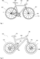
- FIG. 1 is shown as a touring or racing bike bike 100, which is equipped with hubs 1 according to the invention.
- the bike 100 in FIG. 1 has a front wheel 101 and a rear wheel 102, which are held on a frame 103. Furthermore, a handlebar 106 and a saddle 107 is provided. On the front wheel 101 and the rear wheel 102, a rim 110 is provided in each case, which is connected via spokes 109 to the hub 1.
- a radial lock is provided, while at the rear wheel the spokes are at least partially tangentially disposed on the hub to allow the transmission of torque.
- FIG. 2 is a schematic representation of a mountain bike as a bicycle 100 shown, which also has a front wheel 101 and a rear wheel 102 has.
- the Front wheel is held spring loaded on a fork 104, while for the damping of the rear wheel, a damper 105 is available.
- a disc brake 108 serves to effectively brake the bicycle 100.
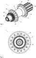
- FIG. 3 shows a perspective view of a designed as a rear hub according to the invention hub 1 for z. B. the bicycle 100 after Fig. 1 or Fig. 2 ,
- the hub 1 has a central part 5 as a hub shell, wherein the hub shell 5 is attached to two end units 3 and 4.
- the end units 3 and 4 have hub flanges 23 and 24, respectively, which are provided with spoke holes 27 for connecting the hub 1 via spokes 109 to a rim 110.
- adapters 33 and 34 are provided at the axial ends of the hub 1, with which the hub 1 is attached to the dropouts of the frame 103.
- the disc brake receptacle 26 serves for fastening a disc brake 108.
- FIG. 4 shows a side view of the hub according to FIG. 3 wherein the hub flange 23 is recognizable on the end unit 3 with the spoke holes 27.
- FIG. 5 is a cross section through the hub 1 shown.
- the hub shell or the central part 5 consists here of a fiber composite material and forms a light yet high-strength connection between the end units 3 and 4 of the hub first
- the hub 1 is rotatably received via bearings 28 relative to the axis 30 designed as a hollow axis.
- the hollow shaft 30 may consist of a metallic alloy and in particular a light metal, but may also consist of at least one or more fiber composite materials.
- the end units 3 and 4 are preferably at least in Essentially of a light metal alloy, but may also be partially or entirely made of fiber composite material.
- the rotor 25 is arranged, which serves to receive one or more pinions.
- the structure of the hub 1 according to the invention is here such that the components used for storage are provided on the end units 3 and 4, so that the hub shell serves as a middle part 5 as a light but firm spacer.
- overlapping areas 8 are provided at both axial ends of the central part 5, at which Einsteckabête 6 of the end units 3 and 4 cooperate with Aufsteckabroughen 7 of the hub shell 5.
- the insertion section 6 of an end unit 3, 4 is inserted into the slip-on section 7 of the hub shell, after a one-component, two-component or multi-component adhesive has been introduced onto the insertion section or into the slip-on section in order to permanently secure connection of the hub shell 5 to the respective one To ensure end unit 3 or 4.
- a toothed disk freewheel 29 is provided as a freewheel, which ensures safe operation via two toothed disks provided with serrations.
- FIG. 6 is an enlarged view of the detail "X" off FIG. 5 shown, wherein a part of the overlap region 8 is shown with the central part 5 and the end unit 3 in cross section.
- a guide section 9 and an adhesive section 10 are provided on the overlapping area 8, wherein the accuracy of fit of the insertion section 6 and the attachment section 7 in the guide section 9 is considerably greater than in the adhesive section 10.
- the adhesive section 10 is a defined radial gap between the insertion portion 6 and the Aufsteckabêt 7 is provided. The gap ensures the defined application of an adhesive layer, so that a permanently secure fit of the middle part 5 can be ensured at the end unit 3.
- a considerable advantage of the construction is that the adhesive area 10 provided axially further inside ensures a reliable adhesive bond between the middle part 5 and the end units 3 and 4, while the guide section 9 or the guide sections 9 provided at both ends 35, 36 of the middle part 5 ensure a defined fit during installation, so that a complex adjustment when gluing the individual housing parts can be omitted.
- FIG. 7 shows a front hub as inventive hub 1 in a cross section.
- the hub 1 has end units 3 and 4 and a middle part 5 arranged therebetween.
- the hub flange 23 is provided on the end unit 3 and the hub flange 24 on the end unit 4.
- Adapters 33 and 34 close to the two ends of the end units 3 and 4, to ensure the inclusion of the front hub 1 on a fork or spring fork 104.
- Overlap areas 8 are provided at the two axial ends 35, 36 of the middle part 5, on which respective insertion sections 6 protrude into the slip-on sections 7 of the hub shell 5.
- the overlapping region 8 extends over an axial width 32, which is composed of the axial width 37 of the guide section 9 and the axial width 38 of the adhesive section 10.
- FIG. 8 shows the detail "X" FIG. 7 greatly enlarged.
- the guide portion 9 extends over an axial width 37 and the adhesive portion 10 extends over an axial Width 38, which together give the axial width 32.
- the axial width 37 of the guide portion 9 here is about 2 mm, the axial width of the adhesive portion 10 in the illustrated embodiment may be between about 5 and 10 mm. This ensures a secure adhesive connection.
- FIGS. 9 to 12 Different variants are shown how an end unit 3 or 4 can be connected to a middle part 5.
- Fig. 9 is a schematic representation of the basic connection according to the FIGS. 6 and 8 shown. It can be clearly seen that two different diameter regions 13 and 14 are provided on the insertion section 6 of the end unit 3. At the guide portion 9, the insertion portion 6 has a larger outer diameter 13 than the smaller outer diameter 14 of the Einsteckabitess 6.
- the inner diameter 15 of the middle part 5 is constant here over the overlap region 8.
- the inner diameter 15 of the central part 5 is constant over its entire length here. Is marked in FIG. 9
- Fig. 10 shows a variant in which also two diameter sections with different outer diameters 13 and 14 are provided on the insertion portion 6 of the end unit 3 and 4, respectively.
- the enlarged outer diameter portion 13 is not provided at the axially outer end of the overlapping portion 8 but at the axially inner end of the overlapping portion 8.
- FIG. 9 has compared to the variant Fig. 10 the advantage that the distances of the guide portions 9 are larger at both ends of the central part 5, so that the same accuracy can be achieved with less effort, as in the embodiment according to Fig. 10 ,
- Fig. 11 another variant is shown in which the insertion portion 6 of the end unit 3 has a constant outside diameter 18.
- the Aufsteckabêt 7 of the middle part 5 has here a reduced inner diameter 17 on the guide portion 9.
- the reduced inner diameter 17 is realized here by a sleeve 20, which may be embodied for example as a metallic sleeve.
- the sleeve 20 may be glued into the interior of the central part 5, but may also be incorporated directly in the manufacture of the central part 5.
- the sleeve 20 is disposed at the axially outer end, as shown in FIG Fig. 11 is shown. But it is also possible to arrange the sleeve 20 axially inside, so that a structure as in Fig. 10 results.
- Fig. 12 shows a variant in which the Aufsteckabites has two diameter portions 15 and 16.
- the area with reduced inner diameter 17 is made in one piece with the hub shell 5.
- the diameter difference 19 which is also present in the embodiments according to the other figures.
- the diameter difference is about 0.1 to 0.3, and preferably about 0.2 mm.
- a hub in which the middle part is inserted on at least one side in an end piece and not attached to it.
- two plug sections are provided.
- An insertion portion has an end of the central portion and on the hub shell and the end unit is formed a Aufsteckabêt.
- Both axial ends of the central part can be identical or different in all embodiments.
- two plug-in sections cooperate, one of which is designed as a plug-in section and one as a slip-on section.
- a guide section and an adhesive section are provided.
- the invention provides an advantageous hub that combines high stability with a low weight.
- the production is simple and due to the overlap region of the male and the slip-on and by the guide portion a particularly high level of ease of assembly and accuracy can be achieved.
Abstract
Description
Die vorliegende Erfindung betrifft eine Nabe für den Einsatz an einem wenigstens teilweise muskelbetriebenen Zweirad und insbesondere einem Fahrrad.The present invention relates to a hub for use on an at least partially muscle-powered bicycle and in particular a bicycle.
Im professionellen Bereich der Fahrradsportler, aber auch im sportlichen Bereich wird zunehmend ein erhebliches Gewicht auf leichte und dennoch feste Komponenten gelegt. Je leichter die Komponenten, desto größer ist die mögliche Beschleunigung und es können auch höhere Maximale- und Durchschnittsgeschwindigkeiten erreicht werden.In the professional field of cyclists, but also in the field of sport, an increasing emphasis is placed on lightweight yet solid components. The lighter the components, the greater the potential acceleration and higher maximum and average speeds can be achieved.
Eine wichtige Komponente bei der Reduktion des Gewichts sind die verwendeten Naben, die einerseits hohen und höchsten Belastungen Stand halten müssen, aber andererseits nicht unbeträchtlich zu dem Gesamtgewicht beitragen.An important component in the reduction of weight are the hubs used, which on the one hand must withstand high and highest loads, but on the other hand contribute not inconsiderably to the overall weight.
Zur Verringerung des Gesamtgewichts einer Nabe sind deshalb im Stand der Technik Naben bekannt geworden, deren Gehäuse teilweise oder vollständig aus einem Faserverbundwerkstoff bestehen. Da die die beiden Nabenflansche verbindende Nabenhülse einen erheblichen Gewichstanteil an der Nabe hat, sind auch Naben bekannt geworden, bei denen die Nabenhülse zwischen den Speichenflanschen aus einem Faserverbundwerkstoff oder einem anderen leichten Material besteht. Bei den bekannten Naben wird die Carbonhülse in eine Aufnahmebohrung der Nabenendteile eingesteckt und dort eingeklebt. Um eine vernünftige Klebung zu gewährleisten, wird ein erheblicher Spalt in radialer Richtung zwischen dem Außendurchmesser der Carbonhülse und dem Innendurchmesser des Aufnahmeloches vorgesehen. Dadurch kann eine vernünftige Klebung gewährleistet werden.In order to reduce the overall weight of a hub, hubs have therefore become known in the prior art whose housings consist partly or completely of a fiber composite material. Since the hub shell connecting the two hub flanges has a significant weight share on the hub, hubs have also become known in which the hub shell between the spoke flanges consists of a fiber composite material or another light material. In the known hub, the carbon sleeve is inserted into a receiving bore of the hub end parts and glued there. To ensure a reasonable bond, a significant Gap is provided in the radial direction between the outer diameter of the carbon sleeve and the inner diameter of the receiving hole. As a result, a reasonable bond can be ensured.
Nachteilig daran ist allerdings, dass die Naben- bzw. Speichenflansche an der Nabenhülse über eine erhebliche Menge an Klebstoff gehalten werden und das ein erheblicher Durchmesser unterschied zwischen der Nabenhülse und der Aufnahmeöffnung in dem Nabenendteil nötig ist. Deshalb wird eine aufwendige Ausrichtung der einzelnen Teile beim Klebevorgang nötig, um die erforderliche Konzentrizität sicher zu stellen. Dadurch kann eine optisch ansprechende und funktionelle Verbundnabe gewährleistet werden.The disadvantage of this, however, is that the hub or Speichenflansche are held on the hub shell over a significant amount of adhesive and that a considerable difference in diameter between the hub shell and the receiving opening in the hub end part is necessary. Therefore, a complex alignment of the individual parts during the bonding process is necessary to ensure the required concentricity. As a result, a visually appealing and functional composite hub can be ensured.
Der Nachteil daran ist, dass ein erheblicher manueller Justageaufwand zur Herstellung der Nabe erforderlich ist, was den Aufwand bei der Herstellung weiter erhöht.The disadvantage of this is that a considerable manual adjustment effort is required for the manufacture of the hub, which further increases the outlay in terms of production.
Es ist deshalb die Aufgabe der vorliegenden Erfindung eine mehrteilige Nabe zur Verfügung zu stellen, welche ein geringes Gewicht aufweist und einen geringeren Justageaufwand erfordert.It is therefore an object of the present invention to provide a multi-part hub, which has a low weight and requires less adjustment effort.
Diese Aufgabe wird gelöst durch eine erfindungsgemäße Nabe mit den Merkmalen des Anspruchs 1 und des Anspruchs 13. Bevorzugte Weiterbildungen der Erfindung sind Gegenstand der Unteransprüche. Weitere Vorteile und Merkmale der Erfindung ergeben sich aus der allgemeinen Beschreibung und der Beschreibung eines Ausführungsbeispiels.This object is achieved by a hub according to the invention with the features of
Die erfindungsgemäße Nabe ist insbesondere für den Einsatz an einem Zweirad und insbesondere an einem muskelbetriebenen Zweirad wie einem Fahrrad vorgesehen. Die erfindungsgemäße Nabe umfasst ein Nabengehäuse, wobei das Nabengehäuse zwei Endeinheiten und wenigstens ein Mittelteil umfasst. Dabei ist das Mittelteil im montierten Zustand zwischen den Endeinheiten angeordnet und daran aufgenommen. Wenigstens eine Endeinheit umfasst einen rohrförmigen Einsteckabschnitt, auf den das Mittelteil mit einem rohrförmigen Aufsteckabschnitt aufgesteckt ist. Dabei überlappen sich der Einsteckabschnitt und der Aufsteckabschnitt in einem Überlappungsbereich. Der Überlappungsbereich umfasst einen Führungsabschnitt und einen Klebeabschnitt.The hub according to the invention is intended in particular for use on a bicycle and in particular on a muscle-operated bicycle such as a bicycle. The hub according to the invention comprises a hub shell, wherein the hub shell comprises two end units and at least one middle part. In this case, the middle part is in the assembled state between the end units arranged and recorded. At least one end unit comprises a tubular insertion portion, on which the middle part is attached with a tubular Aufsteckabschnitt. In this case, the insertion section and the slip-on section overlap in an overlapping area. The overlapping area includes a guide portion and an adhesive portion.
Die erfindungsgemäße Nabe hat viele Vorteile, da sie einen einfachen Aufbau und eine unaufwendige Montage ermöglicht. Dadurch können die Herstellkosten gesenkt werden, während es gleichzeitig möglich ist, das Gesamtgewicht der Nabe zu reduzieren.The hub according to the invention has many advantages, as it allows a simple structure and an inexpensive installation. As a result, the manufacturing costs can be reduced, while at the same time it is possible to reduce the overall weight of the hub.
Die erfindungsgemäße Ausgestaltung ist besonders vorteilhaft, da nicht der gesamte Überlappungsbereich als Klebeabschnitt mit einer erheblichen Dicke des aufgetragenen Klebers vorgesehen wird, sondern es wird ein Führungsabschnitt zur Verfügung gestellt, der die Führung und Justage erheblich erleichtert. Durch den Führungsabschnitt kann die Nabe aus ihren Einzelteilen zusammengebaut und mit dem Kleber zum Kleben versorgt werden, ohne das eine weitere Justage über Lehren erforderlich wird.The embodiment of the invention is particularly advantageous because not the entire overlap region is provided as an adhesive portion with a considerable thickness of the applied adhesive, but it is provided a guide portion available, which greatly facilitates the guidance and adjustment. Through the guide portion, the hub can be assembled from their individual parts and supplied with the adhesive for gluing without requiring further adjustment via gauges.
Ein weiterer erheblicher Vorteil besteht darin, dass weniger und in der Regel keine Nacharbeit erforderlich ist, da ein Entfernen von Leimresten nicht nötig ist.Another significant advantage is that less and usually no reworking is required because a removal of glue residues is not necessary.
Das Mittelteil ist insbesondere hohl und vorzugsweise rohrförmig gestaltet. Es kann einen zylindrischen, runden oder sonstigen Querschnitt aufweisen.The middle part is in particular hollow and preferably tubular. It may have a cylindrical, round or other cross-section.
Insbesondere ist an dem Führungsabschnitt eine geringere Durchmessertoleranz zwischen dem Einsteckabschnitt und dem Aufsteckabschnitt als an dem Klebeabschnitt vorgesehen. Beispielsweise ist es möglich, dass sowohl der Führungsabschnitt als auch der Klebeabschnitt als zylindrische Abschnitte ausgeführt sind. Dann liegen an dem Führungsabschnitt geringere Unterschiede zwischen den Durchmessern des Aufsteckabschnitts und des Einsteckabschnitts vor als in dem Klebeabschnitt.In particular, a smaller diameter tolerance is provided on the guide portion between the male portion and the slip-on portion than at the adhesive portion. For example, it is possible that both the guide portion and the adhesive portion are formed as cylindrical portions are. Then there are minor differences between the diameters of the slip-on section and the insertion section on the guide section than in the adhesive section.
Möglich ist es aber auch, dass an dem Führungsabschnitt der Aufsteckabschnitt und/oder der Einsteckabschnitt über Führungszähne, Erhebungen oder Vertiefungen oder dergleichen örtlich unterschiedliche Durchmesser aufweisen, sodass die Toleranz der beiden ineinander gesteckten Komponenten gegen eine radiale Verschiebung an dem Führungsabschnitt erheblich geringer als an dem Klebeabschnitt ist.But it is also possible that at the guide portion of the Aufsteckabschnitt and / or the insertion over guide teeth, elevations or depressions or the like locally have different diameters, so that the tolerance of the two nested components against a radial displacement at the guide portion considerably less than at the Adhesive section is.
Dadurch wird bei einer sorgfältigen Montage der aufwendige Einsatz von Lehren oder Prüfwerkzeugen zum exakten Aufbau der Nabe überflüssig.As a result, the elaborate use of gauges or test tools for exact construction of the hub is superfluous with a careful installation.
Vorzugsweise weist der Einsteckabschnitt an dem Überlappungsbereich gestufte Außendurchmesser auf und/oder der Aufsteckabschnitt weist einen konstanten Innendurchmesser auf. Beispielsweise kann der Einsteckabschnitt an dem Überlappungsbereich zwei unterschiedliche Außendurchmesser aufweisen, während der Aufsteckabschnitt einen konstanten Innendurchmesser aufweist. Dabei ist der größere Außendurchmesser des Einsteckabschnitts vorzugsweise passgenau an den konstanten Innendurchmesser des Aufsteckabschnitts angepasst, sodass in dem Überlappungsabschnitt des größeren Außendurchmessers mit dem konstanten Innendurchmesser des Aufsteckabschnitts eine erheblich größere Passgenauigkeit erzielt wird, wodurch der Führungsabschnitt realisiert wird.The insertion section preferably has stepped outer diameters at the overlap region and / or the attachment section has a constant inner diameter. For example, the insertion portion at the overlap region may have two different outer diameters, while the slip-on portion has a constant inner diameter. In this case, the larger outer diameter of the insertion section is preferably adapted to fit the constant inner diameter of the Aufsteckabschnitts so that in the overlap portion of the larger outer diameter with the constant inner diameter of the Aufsteckabschnitts a significantly greater accuracy of fit is achieved, whereby the guide portion is realized.
Werden an beiden Enden des Mittelteils solche vergrößerten Außendurchmesser an dem Einsteckabschnitt vorgesehen, so wird die Nabe insgesamt bei der Montage definiert gehalten. Der Klebeabschnitt, an dem ein verringerter Außendurchmesser des Einsteckabschnitts vorliegt, ermöglicht hingegen die Aufnahme einer genügenden Menge des vorgesehenen Klebematerials, um einen zuverlässigen und dauerhaften sicheren Halt der einzelnen Nabenteile zueinander zu ermöglichen.If such enlarged outer diameters are provided on the insertion section at both ends of the central part, then the hub is held in its entirety defined during assembly. The adhesive portion, on which there is a reduced outer diameter of the Einsteckabschnitts, however, allows the inclusion of a sufficient amount of the intended adhesive material to a reliable and permanent secure hold of the to allow individual hub parts to each other.
Der Einsteckabschnitt und der Aufsteckabschnitt weisen besonders bevorzugte runde und insbesondere zylindrische Querschnitte auf. In Varianten ist es aber auch möglich, dass ovale oder eckige Querschnitte vorgesehen sind.The insertion section and the slip-on section have particularly preferred round and in particular cylindrical cross-sections. In variants, it is also possible that oval or square cross-sections are provided.
In allen Ausgestaltungen ist es besonders bevorzugt, dass die Durchmesserdifferenz zwischen dem Innendurchmesser des Aufsteckabschnitts und dem Außendurchmesser des Einsteckabschnitts in dem Klebeabschnitt zwischen 0,2 Prozent und etwa 2 Prozent des Innendurchmessers des Aufsteckabschnitts beträgt. Beispielsweise kann in einem konkreten Beispiel bei einem Durchmesser von etwa 25 bis 30 mm der Durchmesserunterschied zwischen dem Bereich mit größerem Außendurchmesser und dem Bereich mit geringerem Außendurchmesser zwischen etwa 0,1 und 0,4 mm betragen, kann aber auch größer oder kleiner sein. Die genauen Abmessungen hängen auch vom eingesetzten Klebstoff ab.In all embodiments, it is particularly preferred that the difference in diameter between the inner diameter of the Aufsteckabschnitts and the outer diameter of the insertion portion in the adhesive portion is between 0.2 percent and about 2 percent of the inner diameter of the Aufsteckabschnitts. For example, in a specific example, with a diameter of about 25 to 30 mm, the diameter difference between the larger outer diameter portion and the smaller outer diameter portion may be between about 0.1 and 0.4 mm, but may be larger or smaller. The exact dimensions also depend on the adhesive used.
Vorteilhafterweise ist die axiale Breite des Führungsabschnitts kleiner als die axiale Breite des Klebeabschnitts. Dabei kann die axiale Breite des Führungsabschnitts in bevorzugten Ausgestaltungen zwischen etwa 1/10 und 1/2 der Gesamtbreite des Führungsabschnitts und des Klebeabschnitts betragen. In einer konkreten Ausgestaltung kann die axiale Breite des Führungsabschnitts beispielsweise 2 mm betragen, während die axiale Breite des Klebeabschnitts zwischen 4 und 12 mm beträgt.Advantageously, the axial width of the guide portion is smaller than the axial width of the adhesive portion. In this case, the axial width of the guide section may be in preferred embodiments between about 1/10 and 1/2 of the total width of the guide portion and the adhesive portion. In a specific embodiment, the axial width of the guide section may be, for example, 2 mm, while the axial width of the adhesive section is between 4 and 12 mm.
In allen Ausgestaltungen ist es besonders bevorzugt, dass das Mittelteil wenigstens teilweise aus wenigstens einem Faserverbundwerkstoff besteht. Dabei ist der Einsatz unterschiedlichster Materialien möglich und bevorzugt. Das Mittelteil kann aus thermoplastischen oder duroplastischen oder sonstigen Kunststoffen bestehen, die insbesondere mit Verstärkungsfasern verstärkt sind. Möglich ist die Herstellung aus eine einzigen oder aus mehreren Lagen solcher Faserverbundwerkstoffe.In all embodiments, it is particularly preferred that the middle part at least partially consists of at least one fiber composite material. The use of different materials is possible and preferred. The middle part may consist of thermoplastic or thermosetting or other plastics, which are reinforced in particular with reinforcing fibers. The production is possible from a single or several layers of such Fiber composites.
Insbesondere ist der Führungsabschnitt an einem axialen Ende des Überlappungsbereichs angeordnet. Besonders bevorzugt ist der Führungsabschnitt an einem axialen Ende des Mittelteils vorgesehen, wenn sich die Nabe im zusammengebauten Zustand befindet.In particular, the guide portion is disposed at an axial end of the overlapping area. Particularly preferably, the guide portion is provided at an axial end of the central part, when the hub is in the assembled state.
Besonders bevorzugt ist er Führungsabschnitt axial weiter außen als der Klebeabschnitt vorgesehen. Möglich ist es aber auch, dass der Führungsabschnitt am axial inneren Ende des Überlappungsbereichs vorgesehen ist.It is particularly preferred that the guide section is provided axially further outward than the adhesive section. But it is also possible that the guide portion is provided at the axially inner end of the overlap region.
Möglich und bevorzugt ist es auch, dass der Aufsteckabschnitt an dem Überlappungsbereich gestufte Innendurchmesser aufweist, und/oder dass der Einsteckabschnitt einen konstanten Außendurchmesser aufweist. Bei einer solchen Ausgestaltung wird der Führungsabschnitt über einen verkleinerten Innendurchmesser des Aufsteckabschnitts realisiert. Bei solchen Ausgestaltungen ist es bevorzugt, dass der Führungsabschnitt axial weiter innen vorgesehen ist als der Klebeabschnitt, um einen Abstreifen des Klebers bei der Montage möglichst zu verhindern.It is also possible and preferred for the attachment section to have stepped inner diameters at the overlap region, and / or for the insertion section to have a constant outer diameter. In such an embodiment, the guide portion is realized via a reduced inner diameter of the Aufsteckabschnitts. In such embodiments, it is preferred that the guide portion is provided axially further inside than the adhesive portion to prevent stripping of the adhesive during assembly as possible.
Es ist möglich, dass an dem Mittelteil wenigstens eine Hülse aufgenommen ist, welche insbesondere metallisch ausgebildet ist. Über eine solche Hülse, die bei der Herstellung des Mittelteils in das Faserverbundmaterial eingewickelt werden kann, kann ein definierter Sitz des Mittelteils an der fertigen Nabe gewährleistet werden, da bei der Herstellung des Mittelteils die Hülse bzw. die Hülsen definiert in das Mittelteil integriert werden.It is possible that at least one sleeve is received at the middle part, which is in particular made metallic. About such a sleeve which can be wrapped in the manufacture of the central part in the fiber composite material, a defined fit of the central part can be ensured on the finished hub, as defined in the manufacture of the central part of the sleeve or the sleeves in the central part.
Eine andere erfindungsgemäße Nabe weist ein Nabengehäuse auf, wobei das Nabengehäuse zwei Endeinheiten und wenigstens ein Mittelteil umfasst. Das Mittelteil ist zwischen den Endeinheiten angeordnet und daran aufgenommen. Wenigstens eine Endeinheit umfasst einen rohrförmigen Aufsteckabschnitt, in den das Mittelteil mit einem rohrförmigen Einsteckabschnitt eingesteckt ist, wobei sich der Einsteckabschnitt und der Aufsteckabschnitt in einem Überlappungsbereich überlappen und in dem Überlappungsbereich ein Führungsabschnitt und ein Klebeabschnitt vorgesehen sind.Another hub according to the invention has a hub shell, wherein the hub shell comprises two end units and at least one middle part. The middle part is arranged between the end units and received thereon. At least one End unit comprises a tubular Aufsteckabschnitt, in which the central part is inserted with a tubular insertion portion, wherein the male portion and the Aufsteckabschnitt overlap in an overlap region and in the overlap region, a guide portion and an adhesive portion are provided.
Eine solche Nabe ist grundsätzlich ähnlich zu der oben angeführten Nabe aufgebaut. Der Einsteckabschnitt und der Aufsteckabschnitt wirken zusammen. Durch den Führungsabschnitt und den Klebeabschnitt werden eine hohe Montagegenauigkeit und die erforderliche Klebefestigkeit gewährleistet. Wichtig ist, dass zwei Steckabschnitte miteinander zusammenwirken. Dabei ist ein Steckabschnitt als Einsteckabschnitt und es ist einer als Aufsteckabschnitt ausgebildet.Such a hub is basically constructed similar to the above-mentioned hub. The male portion and the slip-on portion cooperate. The guide section and the adhesive section ensure high mounting accuracy and the required adhesive strength. It is important that two plug sections interact with each other. In this case, a plug-in section as a plug-in section and it is designed as a Aufsteckabschnitt.
Insgesamt stellt die Erfindung ein insbesondere geklebtes Nabengehäuse zur Verfügung, welches einfach aufzubauen und zu montieren ist und ein reduziertes Gewicht ermöglicht. Dabei wird mit geringem Montageaufwand eine hohe Genauigkeit erzielt, sodass eine reproduzierbare Konzentrizität gewährleistet werden kann.Overall, the invention provides a particular glued hub shell available, which is easy to assemble and assemble and allows a reduced weight. In this case, high accuracy is achieved with little installation effort, so that a reproducible concentricity can be ensured.
Weitere Vorteile und Merkmale der Erfindung ergeben sich aus dem Ausführungsbeispiel, welches mit Bezug auf die beiliegenden Figuren im Folgenden erläutert wird.Further advantages and features of the invention will become apparent from the embodiment, which will be explained with reference to the accompanying figures below.
In den Figuren zeigen:
- Fig. 1
- ein Fahrrad miterfindungsgemäßen Naben;
- Fig. 2
- ein weiteres Fahrrad mit erfindungsgemäßen Naben;
- Fig. 3
- eine perspektivische Ansicht einer erfindungsgemäßen Hinterradnabe;
- Fig. 4
- eine Seitenansicht der Nabe gemäß
Figur 3 - Fig. 5
- einen Querschnitt durch die
Nabe nach Figur 3 ; - Fig. 6
- das Detail
X aus Figur 5 in vergrößerter Darstellung; - Fig. 7
- eine erfindungsgemäße Vorderradnabe;
- Fig. 8
- das Detail
X aus Figur 7 ; - Fig. 9
- eine schematische geschnittene Darstellung des Überlappungsbereichs einer erfindungsgemäßen Nabe;
- Fig. 10
- eine schematisch geschnittene Darstellung eines weiteren Überlappungsbereichs;
- Fig. 11
- eine schematische Darstellung eines dritten Überlappungsbereichs; und
- Fig. 12
- eine schematische Darstellung eines vierten Überlappungsbereichs.
- Fig. 1
- a bicycle with hubs according to the invention;
- Fig. 2
- another bicycle with hubs according to the invention;
- Fig. 3
- a perspective view of a rear hub according to the invention;
- Fig. 4
- a side view of the hub according to
FIG. 3 ; - Fig. 5
- a cross section through the hub after
FIG. 3 ; - Fig. 6
- the detail X out
FIG. 5 in an enlarged view; - Fig. 7
- a front hub according to the invention;
- Fig. 8
- the detail X out
FIG. 7 ; - Fig. 9
- a schematic sectional view of the overlap region of a hub according to the invention;
- Fig. 10
- a schematic sectional view of another overlapping area;
- Fig. 11
- a schematic representation of a third overlap region; and
- Fig. 12
- a schematic representation of a fourth overlap region.
Mit Bezug auf die beiliegenden
In
In
In
An den Endeinheiten 3 und 4 wird die Nabe 1 über Lager 28 gegenüber der als Hohlachse ausgeführten Achse 30 drehbar aufgenommen. Die Hohlachse 30 kann aus einer metallischen Legierung und insbesondere einem Leichtmetall bestehen, kann aber auch wenigstens aus einem oder mehreren Faserverbundmaterialien bestehen.At the
Die Endeinheiten 3 und 4 bestehen vorzugsweise wenigstens im Wesentlichen aus einer Leichtmetalllegierung, können aber auch teilweise oder ganz aus Faserverbundwerkstoff bestehen.The
An einem axialen Ende der Nabe 1, an dem das Adapterstück 34 vorgesehen ist, wird der Rotor 25 angeordnet, der zur Aufnahme von einem oder mehreren Ritzeln dient.At one axial end of the
Der Aufbau der erfindungsgemäßen Nabe 1 ist hier derart, dass die zur Lagerung eingesetzten Komponenten an den Endeinheiten 3 und 4 vorgesehen sind, sodass die Nabenhülse als Mittelteil 5 als leichter aber fester Abstandshalter dient.The structure of the
Zur Befestigung des Mittelteils 5 an den Endeinheiten 3 und 4 sind an beiden axialen Enden des Mittelteils 5 jeweils Überlappungsbereiche 8 vorgesehen, an denen Einsteckabschnitte 6 der Endeinheiten 3 und 4 mit Aufsteckabschnitten 7 der Nabenhülse 5 zusammenwirken. Zur Montage wird dabei der Einsteckabschnitt 6 einer Endeinheit 3, 4 in den Aufsteckabschnitt 7 der Nabenhülse eingeführt, nachdem ein Ein-, Zwei- oder Mehrkomponentenkleber auf den Einsteckabschnitt oder in den Aufsteckabschnitt eingebracht wurde, um eine dauerhaft sichere Verbindung der Nabenhülse 5 mit der jeweiligen Endeinheit 3 bzw. 4 zu gewährleisten.For attachment of the
Hier im Ausführungsbeispiel ist als Freilauf ein Zahnscheibenfreilauf 29 vorgesehen, der über zwei mit Stirnverzahnungen versehene Zahnscheiben für einen sicheren Betrieb sorgt.Here, in the exemplary embodiment, a
In
Ein erheblicher Vorteil der Konstruktion ist, dass der axial weiter innen vorgesehene Klebebereich 10 eine zuverlässige Klebeverbindung zwischen dem Mittelteil 5 und den Endeinheiten 3 und 4 gewährleistet, während der Führungsabschnitt 9 bzw. die an beiden Enden 35, 36 des Mittelteils 5 vorgesehenen Führungsabschnitte 9 für einen definierten Sitz bei der Montage sorgen, sodass ein aufwendige Justage beim Kleben der einzelnen Gehäuseteile unterbleiben kann.A considerable advantage of the construction is that the
Überlappungsbereiche 8 sind an den beiden axialen Enden 35, 36 des Mittelteils 5 vorgesehen, an denen jeweils Einsteckabschnitte 6 in die Aufsteckabschnitte 7 der Nabenhülse 5 hineinragen. An den beiden axialen Enden 35 und 36 des Mittelteils 5 erstreckt sich jeweils der Überlappungsbereich 8 über eine axiale Breite 32, die sich aus der axialen Breite 37 des Führungsabschnitts 9 und der axialen Breites 38 des Klebeabschnitts 10 zusammensetzt.Overlap
In den
In
Die Ausgestaltung nach
In
In
Möglich ist auch der Aufbau einer Nabe, bei der das Mittelteil auf wenigstens einer Seite in ein Endstück eingesteckt und nicht darauf aufgesteckt ist. Dabei sind auch zwei Steckabschnitte vorgesehen. Einen Einsteckabschnitt weist ein Ende des Mittelteils auf und an dem Nabengehäuse bzw. der Endeinheit ist ein Aufsteckabschnitt ausgebildet.Also possible is the construction of a hub, in which the middle part is inserted on at least one side in an end piece and not attached to it. In this case, two plug sections are provided. An insertion portion has an end of the central portion and on the hub shell and the end unit is formed a Aufsteckabschnitt.
Beide axialen Enden des Mittelteils können in allen Ausgestaltungen gleich oder unterschiedlich ausgebildet sein. In allen Fällen wirken zwei Steckabschnitte zusammen, von denen einer als Einsteckabschnitt und einer als Aufsteckabschnitt ausgebildet sind. Daran sind ein Führungsabschnitt und ein Klebeabschnitt vorgesehen.Both axial ends of the central part can be identical or different in all embodiments. In all cases, two plug-in sections cooperate, one of which is designed as a plug-in section and one as a slip-on section. On this, a guide section and an adhesive section are provided.
Insgesamt stellt die Erfindung eine vorteilhafte Nabe zur Verfügung, die eine hohe Stabilität mit einem geringen Gewicht kombiniert. Die Fertigung ist einfach und aufgrund des Überlappungsbereiches von dem Einsteck- und dem Aufsteckabschnitt und durch den Führungsabschnitt kann eine besonders hohe Montagefreundlichkeit und Genauigkeit erzielt werden.Overall, the invention provides an advantageous hub that combines high stability with a low weight. The production is simple and due to the overlap region of the male and the slip-on and by the guide portion a particularly high level of ease of assembly and accuracy can be achieved.
- 11
- Nabehub
- 22
- Nabengehäusehub housing
- 33
- EndeinheitEnd Unit
- 44
- EndeinheitEnd Unit
- 55
- Mittelteil, NabenhülseMiddle section, hub shell
- 66
- Einsteckabschnittinsertion section
- 77
- Aufsteckabschnittmounting section
- 88th
- Überlappungsbereichoverlap area
- 99
- Führungsabschnittguide section
- 1010
- Klebeabschnittadhesive portion
- 1111
- DurchmessertoleranzDiameter tolerance
- 1212
- DurchmessertoleranzDiameter tolerance
- 1313
- Außendurchmesser, größererOuter diameter, larger
- 1414
- Außendurchmesser, kleinererOuter diameter, smaller
- 1515
- Innendurchmesser, konstantInside diameter, constant
- 1616
- Innendurchmesser, größererInner diameter, larger
- 1717
- Innendurchmesser, kleinererInner diameter, smaller
- 1818
- Außendurchmesser, konstantOuter diameter, constant
- 1919
- DurchmesserdifferenzDiameter difference
- 2020
- Hülseshell
- 2121
- axiales Ende von 8axial end of 8
- 2222
- axiales Ende von 8axial end of 8
- 2323
- Nabenflanschhub flange
- 2424
- Nabenflanschhub flange
- 2525
- Rotorrotor
- 2626
- ScheibenbremsenaufnahmeDisc mount
- 2727
- Speichenlochspoke hole
- 2828
- Lagercamp
- 2929
- ZahnscheibenfreilaufToothed disc freewheel
- 3030
- Achseaxis
- 3131
- Klebeschichtadhesive layer
- 3232
- Breitewidth
- 3333
- Adapterstückadapter piece
- 3434
- Adapterstückadapter piece
- 3535
- EndeThe End
- 3636
- EndeThe End
- 3737
- axiale Breiteaxial width
- 3838
- axiale Breiteaxial width
- 100100
- Fahrradbicycle
- 101101
- Vorderradfront
- 102102
- Hinterradrear wheel
- 103103
- Rahmenframe
- 104104
- Federgabelfork
- 105105
- Hinterraddämpferrear shock absorber
- 106106
- Lenkerhandlebars
- 107107
- Sattelsaddle
- 108108
- Scheibenbremsedisc brake
- 109109
- Speichespoke
- 110110
- Felgerim
Claims (13)
wobei das Nabengehäuse (2) zwei Endeinheiten (3, 4) und wenigstens ein Mittelteil (5) umfasst,
wobei das Mittelteil (5) zwischen den Endeinheiten (3, 4) angeordnet und daran aufgenommen ist,
dadurch gekennzeichnet,
dass wenigstens eine Endeinheit (3, 4) einen rohrförmigen Einsteckabschnitt (6) umfasst, auf den das Mittelteil (5) mit einem rohrförmigen Aufsteckabschnitt (7) aufgesteckt ist, wobei sich der Einsteckabschnitt (6) und der Aufsteckabschnitt (7) in einem Überlappungsbereich (8) überlappen und in dem Überlappungsbereich (8) ein Führungsabschnitt (9) und ein Klebeabschnitt (10) vorgesehen sind.Hub (1) with a hub shell (2),
the hub shell (2) comprising two end units (3, 4) and at least one middle part (5),
the middle part (5) being arranged between the end units (3, 4) and being received thereon,
characterized,
in that at least one end unit (3, 4) comprises a tubular insertion section (6) onto which the middle section (5) is fitted with a tubular attachment section (7), the insertion section (6) and the attachment section (7) being in an overlapping area (8) overlap and in the overlap region (8) a guide portion (9) and an adhesive portion (10) are provided.
wobei das Nabengehäuse (2) zwei Endeinheiten (3, 4) und wenigstens ein Mittelteil (5) umfasst,
wobei das Mittelteil (5) zwischen den Endeinheiten (3, 4) angeordnet und daran aufgenommen ist,
dadurch gekennzeichnet,
dass wenigstens eine Endeinheit (3, 4) einen rohrförmigen Aufsteckabschnitt umfasst, in den das Mittelteil (5) mit einem rohrförmigen Einsteckabschnitt eingesteckt ist, wobei sich der Einsteckabschnitt und der Aufsteckabschnitt in einem Überlappungsbereich (8) überlappen und in dem Überlappungsbereich (8) ein Führungsabschnitt (9) und ein Klebeabschnitt (10) vorgesehen sind.Hub (1) with a hub shell (2),
the hub shell (2) comprising two end units (3, 4) and at least one middle part (5),
the middle part (5) being arranged between the end units (3, 4) and being received thereon,
characterized,
in that at least one end unit (3, 4) comprises a tubular attachment section into which the middle section (5) is inserted with a tubular insertion section, wherein the insertion section and the attachment section overlap in an overlapping area (8) and engage in the overlapping area (8) Guide portion (9) and an adhesive portion (10) are provided.
Applications Claiming Priority (1)
| Application Number | Priority Date | Filing Date | Title |
|---|---|---|---|
| DE102011013536A DE102011013536A1 (en) | 2011-03-10 | 2011-03-10 | Hub for a bicycle |
Publications (2)
| Publication Number | Publication Date |
|---|---|
| EP2497652A1 true EP2497652A1 (en) | 2012-09-12 |
| EP2497652B1 EP2497652B1 (en) | 2015-05-06 |
Family
ID=45851367
Family Applications (1)
| Application Number | Title | Priority Date | Filing Date |
|---|---|---|---|
| EP20120001555 Active EP2497652B1 (en) | 2011-03-10 | 2012-03-07 | Collar for a bicycle |
Country Status (3)
| Country | Link |
|---|---|
| US (1) | US9010875B2 (en) |
| EP (1) | EP2497652B1 (en) |
| DE (1) | DE102011013536A1 (en) |
Families Citing this family (12)
| Publication number | Priority date | Publication date | Assignee | Title |
|---|---|---|---|---|
| EP2777945A2 (en) * | 2013-03-14 | 2014-09-17 | Chosen Co., Ltd. | Bicycle hub assembly |
| DE102013013819A1 (en) * | 2013-08-22 | 2015-02-26 | Dt Swiss Ag | Quick release |
| DE102014117145A1 (en) * | 2014-11-24 | 2016-05-25 | Dt Swiss Ag | Bicycle component with an end stop and end stop |
| US11400754B2 (en) | 2016-07-26 | 2022-08-02 | Dt Swiss Inc. | Hub, in particular for bicycles |
| DE102017116945A1 (en) * | 2016-07-26 | 2018-02-01 | Dt Swiss Ag | Hub especially for bicycles |
| US10995806B2 (en) | 2017-07-26 | 2021-05-04 | Dt Swiss Inc. | Hub, in particular for bicycles |
| US10933691B2 (en) | 2017-07-26 | 2021-03-02 | Dt Swiss Inc. | Hub, in particular for bicycles |
| US10625540B2 (en) | 2017-07-26 | 2020-04-21 | Dt Swiss Inc. | Hub, in particular for bicycles |
| US10549578B2 (en) * | 2016-07-26 | 2020-02-04 | Dt Swiss Inc. | Hub, in particular for bicycles |
| US11332213B2 (en) | 2017-05-30 | 2022-05-17 | Shimano Inc. | Bicycle rear sprocket assembly and bicycle drive train |
| US10946931B2 (en) | 2017-09-22 | 2021-03-16 | Shimano Inc. | Bicycle rear sprocket assembly and bicycle drive train |
| TWI707802B (en) * | 2017-05-30 | 2020-10-21 | 日商島野股份有限公司 | Bicycle rear sprocket assembly and bicycle drive train |
Citations (5)
| Publication number | Priority date | Publication date | Assignee | Title |
|---|---|---|---|---|
| DE4430565A1 (en) * | 1994-08-30 | 1996-03-07 | Anton Link | Bicycle wheel mounting with rolling element bearing |
| US20010005098A1 (en) * | 1999-12-23 | 2001-06-28 | Mavic S.A. | Hub for a spoked wheel, such as a bicycle wheel |
| CN201538196U (en) * | 2009-12-08 | 2010-08-04 | 胡伟 | Shockproof type bicycle hub assembly |
| DE202010000533U1 (en) * | 2009-08-26 | 2010-08-12 | Talon Engineering Ltd., Yeovil | wheel hub |
| CN201646249U (en) * | 2010-03-19 | 2010-11-24 | 胡伟 | Shockproof integral bicycle hub assembly |
Family Cites Families (5)
| Publication number | Priority date | Publication date | Assignee | Title |
|---|---|---|---|---|
| US3170549A (en) * | 1961-06-23 | 1965-02-23 | Gregory Ind | Bicycle coaster brake |
| DE2927138A1 (en) * | 1979-07-05 | 1981-01-08 | Union Sils Van De Loo & Co | Light construction bicycle hub - has plastics body with metal insert bearing shells and press-on spoke supports |
| US5433306A (en) * | 1993-03-11 | 1995-07-18 | Yang; Shu-Chiung C. | Hub assembly for a bicycle |
| DE9403506U1 (en) * | 1994-03-02 | 1994-04-28 | Friedrich Peter | Bicycle hub |
| US7562755B2 (en) * | 2006-07-07 | 2009-07-21 | Dt Swiss, Inc. | Rear wheel hub, in particular for bicycles |
-
2011
- 2011-03-10 DE DE102011013536A patent/DE102011013536A1/en not_active Withdrawn
-
2012
- 2012-03-07 EP EP20120001555 patent/EP2497652B1/en active Active
- 2012-03-09 US US13/416,059 patent/US9010875B2/en active Active
Patent Citations (5)
| Publication number | Priority date | Publication date | Assignee | Title |
|---|---|---|---|---|
| DE4430565A1 (en) * | 1994-08-30 | 1996-03-07 | Anton Link | Bicycle wheel mounting with rolling element bearing |
| US20010005098A1 (en) * | 1999-12-23 | 2001-06-28 | Mavic S.A. | Hub for a spoked wheel, such as a bicycle wheel |
| DE202010000533U1 (en) * | 2009-08-26 | 2010-08-12 | Talon Engineering Ltd., Yeovil | wheel hub |
| CN201538196U (en) * | 2009-12-08 | 2010-08-04 | 胡伟 | Shockproof type bicycle hub assembly |
| CN201646249U (en) * | 2010-03-19 | 2010-11-24 | 胡伟 | Shockproof integral bicycle hub assembly |
Also Published As
| Publication number | Publication date |
|---|---|
| DE102011013536A1 (en) | 2012-09-13 |
| EP2497652B1 (en) | 2015-05-06 |
| US9010875B2 (en) | 2015-04-21 |
| US20120228922A1 (en) | 2012-09-13 |
Similar Documents
| Publication | Publication Date | Title |
|---|---|---|
| EP2497652B1 (en) | Collar for a bicycle | |
| DE102012017115B4 (en) | Bicycle front hub with torsion tube | |
| DE102010064685B4 (en) | Bicycle frame with articulated linkage mounting arrangement | |
| EP3275692B1 (en) | Collar, in particular for bicycles | |
| EP2221192B1 (en) | Bicycle component group with a rotor with front cogging | |
| DE102012016608A1 (en) | Drive hub for e.g. racing vehicle, has sleeve unit that is provided with pinion which is arranged extending in radially outward manner and is spaced apart from axially spaced bearings so as to rotate shaft bearing | |
| EP3023325B1 (en) | Bicycle component having an end stop and end stop | |
| EP2100806A1 (en) | Bicycle component | |
| DE102011015962B4 (en) | Hub for a bicycle | |
| EP2559567A2 (en) | Bicycle component and method for fitting a component | |
| DE102011110199A1 (en) | hub | |
| EP3275693B1 (en) | Collar, in particular for bicycles | |
| DE102016107752A1 (en) | Hub and impeller | |
| EP2930094A1 (en) | Fork components for a bicycle that is at least partially powered by muscle power | |
| DE102011111487A1 (en) | Hub for partial muscle powered vehicle and particularly bicycles, comprises hub housing, which has axis and bearing for rotatably supporting hub housing that has two forged surfaces, which are interconnected by sleeve | |
| EP3517315B1 (en) | Collar, in particular for bicycles | |
| EP3238951B1 (en) | Hub and wheel | |
| EP3862194A1 (en) | Hub, in particular for bicycles | |
| DE102007026821B4 (en) | Hub, especially for bicycles and the like | |
| DE102019002638A1 (en) | Torque transfer assembly for a bicycle | |
| DE102011115534A1 (en) | Wheel hub of motor vehicle has attachment portion that is provided with external thread portion so as to attach nut into base portion | |
| DE102004004106B4 (en) | Freewheel hub with multipart rotor | |
| DE202016004707U1 (en) | Lock ring with speed measuring magnet | |
| DE102018101725A1 (en) | hub |
Legal Events
| Date | Code | Title | Description |
|---|---|---|---|
| PUAI | Public reference made under article 153(3) epc to a published international application that has entered the european phase |
Free format text: ORIGINAL CODE: 0009012 |
|
| AK | Designated contracting states |
Kind code of ref document: A1 Designated state(s): AL AT BE BG CH CY CZ DE DK EE ES FI FR GB GR HR HU IE IS IT LI LT LU LV MC MK MT NL NO PL PT RO RS SE SI SK SM TR |
|
| AX | Request for extension of the european patent |
Extension state: BA ME |
|
| 17P | Request for examination filed |
Effective date: 20130221 |
|
| REG | Reference to a national code |
Ref country code: DE Ref legal event code: R079 Ref document number: 502012003021 Country of ref document: DE Free format text: PREVIOUS MAIN CLASS: B60B0027020000 Ipc: B60B0027040000 |
|
| GRAP | Despatch of communication of intention to grant a patent |
Free format text: ORIGINAL CODE: EPIDOSNIGR1 |
|
| RIC1 | Information provided on ipc code assigned before grant |
Ipc: B60B 27/04 20060101AFI20141030BHEP |
|
| INTG | Intention to grant announced |
Effective date: 20141121 |
|
| GRAS | Grant fee paid |
Free format text: ORIGINAL CODE: EPIDOSNIGR3 |
|
| GRAA | (expected) grant |
Free format text: ORIGINAL CODE: 0009210 |
|
| AK | Designated contracting states |
Kind code of ref document: B1 Designated state(s): AL AT BE BG CH CY CZ DE DK EE ES FI FR GB GR HR HU IE IS IT LI LT LU LV MC MK MT NL NO PL PT RO RS SE SI SK SM TR |
|
| REG | Reference to a national code |
Ref country code: GB Ref legal event code: FG4D Free format text: NOT ENGLISH |
|
| REG | Reference to a national code |
Ref country code: CH Ref legal event code: EP |
|
| REG | Reference to a national code |
Ref country code: IE Ref legal event code: FG4D Free format text: LANGUAGE OF EP DOCUMENT: GERMAN |
|
| REG | Reference to a national code |
Ref country code: AT Ref legal event code: REF Ref document number: 725426 Country of ref document: AT Kind code of ref document: T Effective date: 20150615 |
|
| REG | Reference to a national code |
Ref country code: DE Ref legal event code: R096 Ref document number: 502012003021 Country of ref document: DE Effective date: 20150618 |
|
| REG | Reference to a national code |
Ref country code: NL Ref legal event code: MP Effective date: 20150506 |
|
| REG | Reference to a national code |
Ref country code: LT Ref legal event code: MG4D |
|
| PG25 | Lapsed in a contracting state [announced via postgrant information from national office to epo] |
Ref country code: NO Free format text: LAPSE BECAUSE OF FAILURE TO SUBMIT A TRANSLATION OF THE DESCRIPTION OR TO PAY THE FEE WITHIN THE PRESCRIBED TIME-LIMIT Effective date: 20150806 Ref country code: PT Free format text: LAPSE BECAUSE OF FAILURE TO SUBMIT A TRANSLATION OF THE DESCRIPTION OR TO PAY THE FEE WITHIN THE PRESCRIBED TIME-LIMIT Effective date: 20150907 Ref country code: HR Free format text: LAPSE BECAUSE OF FAILURE TO SUBMIT A TRANSLATION OF THE DESCRIPTION OR TO PAY THE FEE WITHIN THE PRESCRIBED TIME-LIMIT Effective date: 20150506 Ref country code: FI Free format text: LAPSE BECAUSE OF FAILURE TO SUBMIT A TRANSLATION OF THE DESCRIPTION OR TO PAY THE FEE WITHIN THE PRESCRIBED TIME-LIMIT Effective date: 20150506 Ref country code: ES Free format text: LAPSE BECAUSE OF FAILURE TO SUBMIT A TRANSLATION OF THE DESCRIPTION OR TO PAY THE FEE WITHIN THE PRESCRIBED TIME-LIMIT Effective date: 20150506 Ref country code: LT Free format text: LAPSE BECAUSE OF FAILURE TO SUBMIT A TRANSLATION OF THE DESCRIPTION OR TO PAY THE FEE WITHIN THE PRESCRIBED TIME-LIMIT Effective date: 20150506 |
|
| PG25 | Lapsed in a contracting state [announced via postgrant information from national office to epo] |
Ref country code: GR Free format text: LAPSE BECAUSE OF FAILURE TO SUBMIT A TRANSLATION OF THE DESCRIPTION OR TO PAY THE FEE WITHIN THE PRESCRIBED TIME-LIMIT Effective date: 20150807 Ref country code: BG Free format text: LAPSE BECAUSE OF FAILURE TO SUBMIT A TRANSLATION OF THE DESCRIPTION OR TO PAY THE FEE WITHIN THE PRESCRIBED TIME-LIMIT Effective date: 20150806 Ref country code: RS Free format text: LAPSE BECAUSE OF FAILURE TO SUBMIT A TRANSLATION OF THE DESCRIPTION OR TO PAY THE FEE WITHIN THE PRESCRIBED TIME-LIMIT Effective date: 20150506 Ref country code: LV Free format text: LAPSE BECAUSE OF FAILURE TO SUBMIT A TRANSLATION OF THE DESCRIPTION OR TO PAY THE FEE WITHIN THE PRESCRIBED TIME-LIMIT Effective date: 20150506 Ref country code: IS Free format text: LAPSE BECAUSE OF FAILURE TO SUBMIT A TRANSLATION OF THE DESCRIPTION OR TO PAY THE FEE WITHIN THE PRESCRIBED TIME-LIMIT Effective date: 20150906 |
|
| PG25 | Lapsed in a contracting state [announced via postgrant information from national office to epo] |
Ref country code: EE Free format text: LAPSE BECAUSE OF FAILURE TO SUBMIT A TRANSLATION OF THE DESCRIPTION OR TO PAY THE FEE WITHIN THE PRESCRIBED TIME-LIMIT Effective date: 20150506 Ref country code: DK Free format text: LAPSE BECAUSE OF FAILURE TO SUBMIT A TRANSLATION OF THE DESCRIPTION OR TO PAY THE FEE WITHIN THE PRESCRIBED TIME-LIMIT Effective date: 20150506 |
|
| REG | Reference to a national code |
Ref country code: DE Ref legal event code: R097 Ref document number: 502012003021 Country of ref document: DE |
|
| PG25 | Lapsed in a contracting state [announced via postgrant information from national office to epo] |
Ref country code: RO Free format text: LAPSE BECAUSE OF NON-PAYMENT OF DUE FEES Effective date: 20150506 Ref country code: CZ Free format text: LAPSE BECAUSE OF FAILURE TO SUBMIT A TRANSLATION OF THE DESCRIPTION OR TO PAY THE FEE WITHIN THE PRESCRIBED TIME-LIMIT Effective date: 20150506 Ref country code: PL Free format text: LAPSE BECAUSE OF FAILURE TO SUBMIT A TRANSLATION OF THE DESCRIPTION OR TO PAY THE FEE WITHIN THE PRESCRIBED TIME-LIMIT Effective date: 20150506 Ref country code: SK Free format text: LAPSE BECAUSE OF FAILURE TO SUBMIT A TRANSLATION OF THE DESCRIPTION OR TO PAY THE FEE WITHIN THE PRESCRIBED TIME-LIMIT Effective date: 20150506 |
|
| PLBE | No opposition filed within time limit |
Free format text: ORIGINAL CODE: 0009261 |
|
| STAA | Information on the status of an ep patent application or granted ep patent |
Free format text: STATUS: NO OPPOSITION FILED WITHIN TIME LIMIT |
|
| 26N | No opposition filed |
Effective date: 20160209 |
|
| PG25 | Lapsed in a contracting state [announced via postgrant information from national office to epo] |
Ref country code: IT Free format text: LAPSE BECAUSE OF FAILURE TO SUBMIT A TRANSLATION OF THE DESCRIPTION OR TO PAY THE FEE WITHIN THE PRESCRIBED TIME-LIMIT Effective date: 20150506 |
|
| PG25 | Lapsed in a contracting state [announced via postgrant information from national office to epo] |
Ref country code: SI Free format text: LAPSE BECAUSE OF FAILURE TO SUBMIT A TRANSLATION OF THE DESCRIPTION OR TO PAY THE FEE WITHIN THE PRESCRIBED TIME-LIMIT Effective date: 20150506 |
|
| PG25 | Lapsed in a contracting state [announced via postgrant information from national office to epo] |
Ref country code: BE Free format text: LAPSE BECAUSE OF NON-PAYMENT OF DUE FEES Effective date: 20160331 |
|
| PG25 | Lapsed in a contracting state [announced via postgrant information from national office to epo] |
Ref country code: MC Free format text: LAPSE BECAUSE OF FAILURE TO SUBMIT A TRANSLATION OF THE DESCRIPTION OR TO PAY THE FEE WITHIN THE PRESCRIBED TIME-LIMIT Effective date: 20150506 Ref country code: LU Free format text: LAPSE BECAUSE OF FAILURE TO SUBMIT A TRANSLATION OF THE DESCRIPTION OR TO PAY THE FEE WITHIN THE PRESCRIBED TIME-LIMIT Effective date: 20160307 |
|
| REG | Reference to a national code |
Ref country code: CH Ref legal event code: PL |
|
| GBPC | Gb: european patent ceased through non-payment of renewal fee |
Effective date: 20160307 |
|
| REG | Reference to a national code |
Ref country code: IE Ref legal event code: MM4A |
|
| REG | Reference to a national code |
Ref country code: FR Ref legal event code: ST Effective date: 20161130 |
|
| PG25 | Lapsed in a contracting state [announced via postgrant information from national office to epo] |
Ref country code: LI Free format text: LAPSE BECAUSE OF NON-PAYMENT OF DUE FEES Effective date: 20160331 Ref country code: GB Free format text: LAPSE BECAUSE OF NON-PAYMENT OF DUE FEES Effective date: 20160307 Ref country code: CH Free format text: LAPSE BECAUSE OF NON-PAYMENT OF DUE FEES Effective date: 20160331 Ref country code: IE Free format text: LAPSE BECAUSE OF NON-PAYMENT OF DUE FEES Effective date: 20160307 Ref country code: FR Free format text: LAPSE BECAUSE OF NON-PAYMENT OF DUE FEES Effective date: 20160331 |
|
| PG25 | Lapsed in a contracting state [announced via postgrant information from national office to epo] |
Ref country code: SE Free format text: LAPSE BECAUSE OF FAILURE TO SUBMIT A TRANSLATION OF THE DESCRIPTION OR TO PAY THE FEE WITHIN THE PRESCRIBED TIME-LIMIT Effective date: 20150506 Ref country code: NL Free format text: LAPSE BECAUSE OF FAILURE TO SUBMIT A TRANSLATION OF THE DESCRIPTION OR TO PAY THE FEE WITHIN THE PRESCRIBED TIME-LIMIT Effective date: 20150506 |
|
| PG25 | Lapsed in a contracting state [announced via postgrant information from national office to epo] |
Ref country code: MT Free format text: LAPSE BECAUSE OF FAILURE TO SUBMIT A TRANSLATION OF THE DESCRIPTION OR TO PAY THE FEE WITHIN THE PRESCRIBED TIME-LIMIT Effective date: 20150506 |
|
| REG | Reference to a national code |
Ref country code: AT Ref legal event code: MM01 Ref document number: 725426 Country of ref document: AT Kind code of ref document: T Effective date: 20170307 |
|
| PG25 | Lapsed in a contracting state [announced via postgrant information from national office to epo] |
Ref country code: CY Free format text: LAPSE BECAUSE OF FAILURE TO SUBMIT A TRANSLATION OF THE DESCRIPTION OR TO PAY THE FEE WITHIN THE PRESCRIBED TIME-LIMIT Effective date: 20150506 Ref country code: HU Free format text: LAPSE BECAUSE OF FAILURE TO SUBMIT A TRANSLATION OF THE DESCRIPTION OR TO PAY THE FEE WITHIN THE PRESCRIBED TIME-LIMIT; INVALID AB INITIO Effective date: 20120307 Ref country code: SM Free format text: LAPSE BECAUSE OF FAILURE TO SUBMIT A TRANSLATION OF THE DESCRIPTION OR TO PAY THE FEE WITHIN THE PRESCRIBED TIME-LIMIT Effective date: 20150506 |
|
| PG25 | Lapsed in a contracting state [announced via postgrant information from national office to epo] |
Ref country code: MK Free format text: LAPSE BECAUSE OF FAILURE TO SUBMIT A TRANSLATION OF THE DESCRIPTION OR TO PAY THE FEE WITHIN THE PRESCRIBED TIME-LIMIT Effective date: 20150506 Ref country code: TR Free format text: LAPSE BECAUSE OF FAILURE TO SUBMIT A TRANSLATION OF THE DESCRIPTION OR TO PAY THE FEE WITHIN THE PRESCRIBED TIME-LIMIT Effective date: 20150506 |
|
| PG25 | Lapsed in a contracting state [announced via postgrant information from national office to epo] |
Ref country code: AT Free format text: LAPSE BECAUSE OF NON-PAYMENT OF DUE FEES Effective date: 20170307 |
|
| PG25 | Lapsed in a contracting state [announced via postgrant information from national office to epo] |
Ref country code: AL Free format text: LAPSE BECAUSE OF FAILURE TO SUBMIT A TRANSLATION OF THE DESCRIPTION OR TO PAY THE FEE WITHIN THE PRESCRIBED TIME-LIMIT Effective date: 20150506 |
|
| PGFP | Annual fee paid to national office [announced via postgrant information from national office to epo] |
Ref country code: DE Payment date: 20230320 Year of fee payment: 12 |
|
| P01 | Opt-out of the competence of the unified patent court (upc) registered |
Effective date: 20230517 |