EP2497638B1 - Kartenlaminiervorrichtung mit Direktheizung - Google Patents
Kartenlaminiervorrichtung mit Direktheizung Download PDFInfo
- Publication number
- EP2497638B1 EP2497638B1 EP12158667.1A EP12158667A EP2497638B1 EP 2497638 B1 EP2497638 B1 EP 2497638B1 EP 12158667 A EP12158667 A EP 12158667A EP 2497638 B1 EP2497638 B1 EP 2497638B1
- Authority
- EP
- European Patent Office
- Prior art keywords
- lamination
- head
- card
- patch
- unit
- Prior art date
- Legal status (The legal status is an assumption and is not a legal conclusion. Google has not performed a legal analysis and makes no representation as to the accuracy of the status listed.)
- Not-in-force
Links
- 238000003475 lamination Methods 0.000 title claims description 188
- 238000010438 heat treatment Methods 0.000 title claims description 86
- 238000012546 transfer Methods 0.000 claims description 28
- 230000003028 elevating effect Effects 0.000 claims description 21
- 230000001174 ascending effect Effects 0.000 claims description 20
- 238000004891 communication Methods 0.000 claims description 9
- 238000004804 winding Methods 0.000 claims description 8
- 238000009434 installation Methods 0.000 claims description 4
- 238000000034 method Methods 0.000 description 31
- 239000011248 coating agent Substances 0.000 description 14
- 238000000576 coating method Methods 0.000 description 14
- 239000000463 material Substances 0.000 description 9
- 238000010030 laminating Methods 0.000 description 5
- 238000004519 manufacturing process Methods 0.000 description 5
- 230000008901 benefit Effects 0.000 description 4
- 238000012423 maintenance Methods 0.000 description 4
- 238000007639 printing Methods 0.000 description 4
- 238000003825 pressing Methods 0.000 description 3
- 239000000919 ceramic Substances 0.000 description 2
- 238000007796 conventional method Methods 0.000 description 2
- 230000007423 decrease Effects 0.000 description 2
- 238000010586 diagram Methods 0.000 description 2
- 230000008569 process Effects 0.000 description 2
- 239000000758 substrate Substances 0.000 description 2
- 239000002699 waste material Substances 0.000 description 2
- OKTJSMMVPCPJKN-UHFFFAOYSA-N Carbon Chemical compound [C] OKTJSMMVPCPJKN-UHFFFAOYSA-N 0.000 description 1
- RYGMFSIKBFXOCR-UHFFFAOYSA-N Copper Chemical compound [Cu] RYGMFSIKBFXOCR-UHFFFAOYSA-N 0.000 description 1
- 238000005299 abrasion Methods 0.000 description 1
- 230000009471 action Effects 0.000 description 1
- 229910052799 carbon Inorganic materials 0.000 description 1
- 239000002131 composite material Substances 0.000 description 1
- 229920001940 conductive polymer Polymers 0.000 description 1
- 239000000470 constituent Substances 0.000 description 1
- 229910052802 copper Inorganic materials 0.000 description 1
- 239000010949 copper Substances 0.000 description 1
- 230000002950 deficient Effects 0.000 description 1
- 238000013461 design Methods 0.000 description 1
- 238000011161 development Methods 0.000 description 1
- 238000009826 distribution Methods 0.000 description 1
- 230000000694 effects Effects 0.000 description 1
- 238000005516 engineering process Methods 0.000 description 1
- 229910052736 halogen Inorganic materials 0.000 description 1
- 150000002367 halogens Chemical class 0.000 description 1
- 230000007246 mechanism Effects 0.000 description 1
- 239000002184 metal Substances 0.000 description 1
- 229910052751 metal Inorganic materials 0.000 description 1
- 238000012986 modification Methods 0.000 description 1
- 230000004048 modification Effects 0.000 description 1
- 239000011253 protective coating Substances 0.000 description 1
- 230000001681 protective effect Effects 0.000 description 1
- 230000000284 resting effect Effects 0.000 description 1
- 238000005096 rolling process Methods 0.000 description 1
- 239000012780 transparent material Substances 0.000 description 1
- 238000010792 warming Methods 0.000 description 1
Images


Classifications
-
- B—PERFORMING OPERATIONS; TRANSPORTING
- B32—LAYERED PRODUCTS
- B32B—LAYERED PRODUCTS, i.e. PRODUCTS BUILT-UP OF STRATA OF FLAT OR NON-FLAT, e.g. CELLULAR OR HONEYCOMB, FORM
- B32B37/00—Methods or apparatus for laminating, e.g. by curing or by ultrasonic bonding
- B32B37/06—Methods or apparatus for laminating, e.g. by curing or by ultrasonic bonding characterised by the heating method
-
- B—PERFORMING OPERATIONS; TRANSPORTING
- B32—LAYERED PRODUCTS
- B32B—LAYERED PRODUCTS, i.e. PRODUCTS BUILT-UP OF STRATA OF FLAT OR NON-FLAT, e.g. CELLULAR OR HONEYCOMB, FORM
- B32B37/00—Methods or apparatus for laminating, e.g. by curing or by ultrasonic bonding
- B32B37/0046—Methods or apparatus for laminating, e.g. by curing or by ultrasonic bonding characterised by constructional aspects of the apparatus
-
- B—PERFORMING OPERATIONS; TRANSPORTING
- B32—LAYERED PRODUCTS
- B32B—LAYERED PRODUCTS, i.e. PRODUCTS BUILT-UP OF STRATA OF FLAT OR NON-FLAT, e.g. CELLULAR OR HONEYCOMB, FORM
- B32B37/00—Methods or apparatus for laminating, e.g. by curing or by ultrasonic bonding
- B32B37/14—Methods or apparatus for laminating, e.g. by curing or by ultrasonic bonding characterised by the properties of the layers
- B32B37/16—Methods or apparatus for laminating, e.g. by curing or by ultrasonic bonding characterised by the properties of the layers with all layers existing as coherent layers before laminating
- B32B37/22—Methods or apparatus for laminating, e.g. by curing or by ultrasonic bonding characterised by the properties of the layers with all layers existing as coherent layers before laminating involving the assembly of both discrete and continuous layers
-
- B—PERFORMING OPERATIONS; TRANSPORTING
- B32—LAYERED PRODUCTS
- B32B—LAYERED PRODUCTS, i.e. PRODUCTS BUILT-UP OF STRATA OF FLAT OR NON-FLAT, e.g. CELLULAR OR HONEYCOMB, FORM
- B32B41/00—Arrangements for controlling or monitoring lamination processes; Safety arrangements
-
- B—PERFORMING OPERATIONS; TRANSPORTING
- B32—LAYERED PRODUCTS
- B32B—LAYERED PRODUCTS, i.e. PRODUCTS BUILT-UP OF STRATA OF FLAT OR NON-FLAT, e.g. CELLULAR OR HONEYCOMB, FORM
- B32B2429/00—Carriers for sound or information
-
- B—PERFORMING OPERATIONS; TRANSPORTING
- B32—LAYERED PRODUCTS
- B32B—LAYERED PRODUCTS, i.e. PRODUCTS BUILT-UP OF STRATA OF FLAT OR NON-FLAT, e.g. CELLULAR OR HONEYCOMB, FORM
- B32B37/00—Methods or apparatus for laminating, e.g. by curing or by ultrasonic bonding
- B32B37/02—Methods or apparatus for laminating, e.g. by curing or by ultrasonic bonding characterised by a sequence of laminating steps, e.g. by adding new layers at consecutive laminating stations
- B32B37/025—Transfer laminating
-
- Y—GENERAL TAGGING OF NEW TECHNOLOGICAL DEVELOPMENTS; GENERAL TAGGING OF CROSS-SECTIONAL TECHNOLOGIES SPANNING OVER SEVERAL SECTIONS OF THE IPC; TECHNICAL SUBJECTS COVERED BY FORMER USPC CROSS-REFERENCE ART COLLECTIONS [XRACs] AND DIGESTS
- Y10—TECHNICAL SUBJECTS COVERED BY FORMER USPC
- Y10T—TECHNICAL SUBJECTS COVERED BY FORMER US CLASSIFICATION
- Y10T156/00—Adhesive bonding and miscellaneous chemical manufacture
- Y10T156/17—Surface bonding means and/or assemblymeans with work feeding or handling means
Definitions
- the present invention relates to a direct heating type card lamination apparatus, and more particularly, to a direct heating type card lamination apparatus with a concise and simple structure that performs low power lamination by applying heat directly on a card and performs lamination conveniently and quickly without a waiting time.
- plastic cards such as a credit card, a cash card, a transportation card, a membership card, a medical card, an identification card are used in today's society.
- a lamination patch (called "coating film") of a transparent material is attached on the plastic card to protect a printed surface such as an image, a design, a letter, etc., printed on the surface of the plastic card.
- the lamination patch employs an attachment method by heat in a state that the lamination patch is disposed on the card.
- Diverse types of devices for card lamination are disclosed as described below.
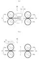
- FIG. 1 to FIG. 4 schematically show main constituent elements of a conventional card lamination apparatus.
- a card lamination apparatus 10 which is called a heat plate heating method, includes a lamination unit 13 disposed between inserting rollers 11 for inserting a card a and dispensing rollers 12 for dispensing a card.
- a heat plate 13a of the lamination unit 13 is separately disposed between a lower inserting roller 11a and an upper dispensing roller 12a to apply heat to a lamination patch b.
- a heater 13b for applying heat to the card is installed between a lower inserting roller 11b and a lower dispensing roller 12b.
- the card lamination apparatus 10 shown in FIG. 1 is configured to dispose the heater 13b and the heat plate 13a for lamination separately to prevent direct contact with the patch b or the card. Accordingly, in the middle of passing through the heat plate 13a and the heater 13b, the card a and the lamination patch b are attached to each other by heat.
- the card lamination apparatus 10 has an advantage that it is relatively inexpensive and has a superior durability. However, since the card lamination apparatus 10 does not adopt a method that heat is applied through direct contact with the lamination patch b, there is a high possibility that bubbles are generated to cause production of defective products.
- a card lamination apparatus 20 shown in FIG. 2 adopts a heating method that a heater 23 installed on an upper inserting roller 21a for inserting a card transfers heat to an entire upper inserting roller 21a.
- This heating method is called an indirect roller heating method and is generally adopted for a photograph coating device.
- the indirect roller heating method is a method that a heat cover 24 besides the heater 23 is individually included to be a medium for transferring heat to the roller. Accordingly, the indirect roller heating method has disadvantages that heat transfer speed is slow and the roller needs to be washed frequently.
- a card lamination apparatus 30 shown in FIG. 3 includes lamination units respectively disposed between inserting rollers 31 for inserting a card and dispensing rollers 32 for dispensing a card, and also disposed over inserting rollers 31. That is, a heat plate 33 as the lamination unit is separately disposed between an upper inserting roller 31a and an upper dispensing roller 32a to apply heat to a lamination patch b. A heater 34 for applying heat to a card is installed between a lower inserting roller 31b and a lower dispensing roller 32b. Also, a heater 35 and a heat cover 36 are installed on the upper inserting roller 31a.
- the card lamination apparatus 30 adopts a composite heating method that the heat plate heating method of FIG. 1 and the indirect roller heating method of FIG. 2 are combined to compensate for shortcomings of the two methods. Therefore, the card lamination apparatus 30 shows a fast speed and is capable of coating a photograph. However, the card lamination apparatus 30 and has disadvantages that it is expensive and its roller needs to be washed.
- a card lamination apparatus 40 shown in FIG. 4 includes a lamination unit 43 inside an inserting roller 41 for inserting a card. Since a heater as the lamination unit 43 is included inside an upper inserting roller 41a, the card a including the lamination patch b is heated and compressed in the middle of passing through a space between the upper and lower inserting rollers 41a and 41b.
- the card lamination apparatus 40 adopts a direct compressing method by the hot roller, which is called a hot roller method or a direct roller heating method.
- a halogen lamp or a hot-wire type cartridge is applied as a heater for performing lamination.
- the direct roller heating method shown in FIG. 4 requires a high-capacity heater consuming great power ranging about 200 to 300w since lamination can be performed after heating the upper inserting roller 41a due to heat generated from a heater 43 installed inside the upper inserting roller 41a. That is, the direct roller heating method has a disadvantage that power consumption is too great.
- the upper inserting roller 41a needs to be heated to high temperature of 150°C or more in order to perform lamination. Since about 2 to 5 minutes are required for increasing surface temperature of a roller having a large diameter, there is an inconvenience in use due to too long waiting time, i.e., warming up time.
- the above-mentioned direct roller heating method has a disadvantage that a great amount of energy is wasted since the heater 43 should unnecessarily maintain a turn-on state to quickly perform lamination and the upper inserting roller 41a heated by the heater emits heat in an entire direction of 360° regardless of lamination besides a lower direction.
- the direct roller heating method requires a device for elevation since a roller ascends and descends onto a card to perform lamination.
- the direct roller heating method also requires a device for a rotary motion since the roller moves as a cloud on a surface of the card. Accordingly, the direct roller heating method has a complicated structure to cause increase of manufacturing cost, frequent troubles and difficulty in maintenance.
- US6095220 discloses an overcoat fixing device that fixes a coat film on a front surface of a recording medium by heating.
- the overcoat fixing device is formed of a transferring device for transferring the recording medium along a transferring path, a fixing device provided in the transferring path and fixing the coat film to the recording medium, and a pressing device provided in the transferring path away from the fixing device and pressing one surface of the recording medium on which the coat film is fixed.
- the pressing device presses the recording medium with the coat film sent from the fixing device by the transferring device for a predetermined time while stopping at a predetermined position.
- EP0835739 discloses a coating system which enables protective coating on both the recording surfaces of a recording medium such as identification cards, license cards, and credit cards by use of a single coating unit capable of coating only one surface of the card-like recording medium.
- a coating system which enables protective coating on both the recording surfaces of a recording medium such as identification cards, license cards, and credit cards by use of a single coating unit capable of coating only one surface of the card-like recording medium.
- the recording medium is turned over by operating transporting-turning means and again sent to the coating position, so that the other surface is coated there.
- the system may incorporate a printing unit for printing the recording medium or be attached to an individual printer.
- US 2002/134516 A1 discloses a laminator that includes: an infeed which supplies plastic cards which are to be laminated with a plastic laminating material on a first side of each card; a laminating station having a heated roller and a card support, opposed to the heated roller, which supports a second side of each card and is separated from the heated roller to define a card opening through which each plastic card passes when being laminated; a laminate source which feeds plastic laminating material into the card opening between the heated roller and the first side of each plastic card with heat from the heated roller heating the plastic laminating material and each plastic card in the card opening to fuse the plastic laminating material to the first surface of each plastic card; and a card bowing the station, which bows each card sufficiently in a portion thereof to cause each card when cooled to be substantially flat.
- the present invention is invented based on the above description and an embodiment of the present invention is to provide a direct heating type card lamination apparatus that performs lamination with low power by applying heat directly on a card in a moment.
- Another embodiment of the present invention is to provide a direct heating type card lamination apparatus that conveniently and quickly perform lamination without a waiting time.
- Still another embodiment of the present invention is to provide a direct heating type card lamination apparatus that has a simple and concise structure, reduce a manufacturing cost and a maintenance cost by efficiently performing lamination, thereby reducing a resting time.
- a direct heating type card lamination apparatus including: a card transferring unit for transferring a card; a patch supplying unit for supplying a lamination patch to be coated on a surface of the card; a lamination head disposed on a transfer route of a card to be momentarily heated by an applied power; and a head elevating unit for performing pressurization to coat a lamination patch on the card by descending the lamination head, and when completely coated, by ascending the lamination head to an original position.
- the lamination head comprises a head case, a planar heating element installed inside a lower portion of the head case to be momentarily heated by an applied power, a heat emitting member installed in a lower portion thereof to emit heat generated and applied from the planar heating element to the lamination patch, and a temperature sensing unit installed in the head case to sense a heating temperature of the planar heating element.
- the head elevating unit comprises a head fixing member installed inside a frame to mount the lamination head, a head ascending member movably installed in the head fixing member to move the lamination head connected to an end thereof by an applied external force, a head pressurizing member for applying a driving force to the head ascending member such that the lamination head moves toward the card to perform lamination, and a head returning member for applying a return force to the head ascending member to return the lamination head to an original position after performing lamination.
- the head fixing member comprises a fixer installed on the frame and a supporter having a pair of longitudinal members that stand upright for guiding and supporting elevation movement of the head ascending member.
- the head ascending member comprises a transverse member installed between the pair of longitudinal members of the head fixing member to be capable of elevating in a transverse direction, and a connecting rod connected to a lower portion of the transverse member to contact with the lamination head at a lower end.
- the patch supplying unit may include: a patch roll wound in a roll shape by attaching a plurality of lamination patches on a film of a band form; a patch supply roll, in which the patch roll is installed; and a patch winding roll withdrawn from the patch roll wherein a film portion where lamination is performed is wound via the lamination head.
- the card transferring unit may include a plurality of upper and lower transfer rollers along a card transfer route, which are installed to face each other up and down such that a frictional force for transferring the card acts, and a support roller for supporting a card when the lamination head descends in a lower side of the card transfer route corresponding to an installation position of the lamination head.
- the card lamination apparatus may include: an input unit for inputting a control signal; a communication module for receiving an input signal transferred from an external device; and a control unit for controlling operations of the card transferring unit, the patch supplying unit, the lamination head and the head elevating unit according to an input signal from the input unit and the communication module.
- a direct heating type card lamination apparatus embodying the present invention does not perform lamination by a heated roller after heating the roller with a heating element according to a conventional method but performs lamination by directly applying heat on a card by a momentarily heated lamination head. Accordingly, the direct heating type card lamination apparatus quickly and conveniently performs lamination with low power without energy loss or a waiting time.
- the direct heating type card lamination apparatus has a simple and concise structure that lamination is performed only by elevation movement of a lamination head, a manufacturing cost is reduced and it is easy to be maintained due to a few troubles to reduce a cost for maintenance.
- FIG. 5 is a view describing a technical concept of a direct heating type card lamination apparatus according to the present invention.
- FIG. 6 is a schematic view showing the direct heating type card lamination apparatus according to an exemplary embodiment.
- FIG. 7 is a block diagram showing the direct heating type card lamination apparatus according to an exemplary embodiment.
- a the direct heating type card lamination apparatus 100 coats a lamination patch b by momentarily applying heat directly on a transferred card a and includes a frame 110, a card transferring unit 120, a patch supplying unit 130, a lamination head 140, and a head elevating unit 150.
- the direct heating type card lamination apparatus 100 with the structure as described above is configured such that lamination is performed by transferring the card a by the card transferring unit 120 under the control of a control unit 180 below, supplying the lamination patch b on a coating surface of the card by the patch supplying unit 130 at the same time, and elevating the lamination head 140 by the head elevating unit 150.
- the direct heating type card lamination apparatus further includes an input unit 160, a communication module 170, the control unit 180, a power unit 190, and a display unit 210.
- the input unit 160 inputs diverse control signals such as an on/off control button of power and the communication module 170 is a device for receiving an input signal transferred from diverse external devices such as a computer, and a wired or wireless communication terminal.
- the control unit 180 is an element for controlling driving of the card transferring unit 120, the patch supplying unit 130, the lamination head 140 and the head elevating unit 150 according to input signals from the input unit 160 and the communication module 170.
- the control unit 180 includes a Mycom storing a program for controlling each of the above-mentioned elements.
- the power unit 190 is an element for receiving commercial power from outside and applying the power to each element.
- the display unit 210 is a display window installed on an external case (not shown), which is overlaid on an outside of the frame 110 to display an input signal and an operation state of the card lamination apparatus.
- the card transferring unit 120 is installed inside the frame 110 to transfer the card a along a predetermined route. As shown in FIG. 5 , upper and lower transfer rollers 121 and 122 are installed to face each other up and down such that a frictional force for transferring the card a works.
- the card transferring unit 120 efficiently performs the transferring action by disposing a plurality of up-and-down transfer rollers 121 and 122 along a transfer route of the card, and including a transfer guiding member 123 on the frame 110 corresponding to disposition regions for guiding the transfer of the card a and supporting the upper and lower transfer rollers 121 and 122.
- the card transferring unit 120 includes a support roller 124 in a lower side of the transfer route of the card a corresponding to an installation location of the lamination head 140.
- the support roller 124 makes a holding force to work between the card a and the lamination patch b by supporting the card when the lamination head 140 descends.
- the card transferring unit 120 includes a driving unit (not specifically shown) for the card transferring unit for rolling the upper and lower transfer rollers 121 and 122.
- the driving unit for the card transferring unit may apply diverse driving methods that are applied to rotate a roller in a card printing filed.
- the driving unit (not shown) for the card transferring unit may be comprised of a driving motor (not shown) including a driven gear (not shown) installed on a central axis of the upper and lower transfer rollers 121 or 122, an electronic gear (not shown) engaged with the driven gear, and a driving gear (not shown) engaged with the electronic gear.
- the driving unit for the card transferring unit may be configured by applying a power transferring method configured to transfer power of the driving motor to the upper and lower transfer rollers 121 and 122 by a belt besides the above-mentioned power transferring method using the gear.
- FIG. 8 is a view showing a patch supplying unit, which is applied to the direct heating type card lamination apparatus according to an exemplary embodiment.
- FIG. 8 is a conceptual view showing the main elements schematically.
- the patch supplying unit 130 supplies the lamination patch b coated on a surface of the card. If the lamination patch is supplied precisely to a location for lamination, the patch supplying unit 130 of diverse structures or shapes may be configured without limitation. However, in this exemplary embodiment, the patch supplying unit 130 is configured to include a patch roll 131, a patch supply roll 132, and a patch winding roll 133 for the convenience of installation and exchange work.
- the patch roll 131 a plurality of lamination patches b are attached on a film 131a of a band form at regular intervals and wound in a roll shape.
- the patch roll 131 is installed on the patch supply roll 132.
- the waste film 131a in which lamination is performed, is wound via the lamination head 140 after being withdrawn from the patch roll 131.
- the patch supplying unit 130 includes a driving unit for the patch supplying unit (not specifically shown) that moves a film in the process of performing lamination.
- the driving unit for the patch supplying unit may have diverse structures under the condition that it adopts a method of pulling and unwinding the film, which is wound in the patch supply roll 132, by rotating the patch winding roll 133.
- the driving unit for the patch supplying unit may be comprised of a driving motor (not shown) including a driven gear (not shown) installed on a central axis 133a of the patch winding roll 133, an electronic gear (not shown) engaged with the driven gear, and a driving gear (not shown) engaged with the electronic gear.
- the driving unit for the patch supplying unit may receive and use torque, which is generated in the driving motor of the above-mentioned card transferring unit 120, by using a power transferring member such as a gear as a medium without an individually equipped driving motor (not shown).
- FIG. 9 is a view showing a lamination head, which is applied to the direct heating type card lamination apparatus according to an exemplary embodiment.
- FIG. 9 shows a structure briefly for better understanding.
- the lamination head 140 is disposed on a transfer route of the card a and heated momentarily by the applied power to emit heat. As shown in FIG. 9 , the lamination head 140 is configured to include a heating element 142, a heat emitting member 143, and a temperature sensing unit 144 inside a head case 141, which is formed in a hexahedral shape of a square pillar form.
- the heating element 142 is installed inside a lower portion of the head case 141 and generates heat while being heated by the applied power. Any heating means that emit heat while being momentarily and quickly heated by applying power may be adopted as the heating element 142 without limitation.
- a planar heating element of a thin plate is adopted. Materials of the planar heating element may include metal include copper, carbon and conductive polymer as materials that generate heat by electric resistance when power is applied.
- the heat emitting member 143 may be formed in or coupled to a lower portion of the heating element 142 to emit the heat generated and applied from the heating element 142.
- the heat emitting member 143 may be formed by coating a material having a superior heating property or be installed by adding a member of a thin plate made of a material having a superior heating property.
- the heat emitting member 143 may be configured by coating a coating material having a superior heat transfer efficiency and a low frictional coefficient or adding a thin plate made of ceramic.
- the temperature sensing unit 144 is installed inside the head case 141 to sense a heating temperature of the heating element 142.
- a temperature sensor including a negative temperature coefficient (NTC) thermistor element and a positive temperature coefficient (PTC) thermistor element may be installed.
- the NTC thermistor element has a property of a negative resistance temperature coefficient that when a temperature increases, a resistance value decreases.
- the PTC thermistor element has a property of a constant resistance temperature coefficient that when the temperature increases, the resistance value increases.
- the head elevating unit 150 applies pressure by descending the lamination head 140 to coat the lamination patch b on the card a. When the coating is completed, the head elevating unit 150 ascends the lamination head 140 again. Diverse mechanisms for efficiently ascending and descending the lamination head 140 under the control of the control unit 180 may be applied. As shown in FIG. 6 , in this exemplary embodiment, the head elevating unit 150 includes a head fixing member 151, a head ascending member 152, a head pressurizing member 153, and a head returning member 154.
- the head fixing member 151 is installed inside the frame 110 such that the lamination head 140 is installed.
- the head fixing member 151 includes a fixer 151a installed on the frame 110 and a supporter 151b for guiding and supporting elevation movement of the head ascending member 152 below.
- the supporter 151b includes a pair of longitudinal members, which are formed to stand upright.
- the head ascending member 152 is movable installed on the head fixing member 151 and contacts with the lamination head 140 at one end.
- lamination is performed by moving the lamination head 140 toward a card.
- elastic force acts from the head returning member 154, the head ascending member 152 returns the lamination head 140 to an original position.
- the head ascending member 152 includes a transverse member 152a and a connecting rod 152b.
- the transverse member 152a is installed between supporters 151b of the head fixing member 151 to be capable of elevating in a transverse direction.
- the connecting rod 152b is connected to a lower portion of the transverse member 152a to contact with the lamination head 140 at a lower end.
- the head pressurizing member 153 moves the lamination head 140 toward the card a to perform lamination.
- the head pressurizing member 153 is installed in the frame 110 and includes an eccentric cam that moves the lamination head 140 toward the card a by pressurizing the transverse member 152a by an eccentric portion 153a when rotating.
- a cam shaft 155 is installed on a center of the eccentric cam.
- a gear (not shown) or a pulley (not shown) receiving torque is installed on an end portion of the cam shaft 155 and rotate the eccentric cam while rotating to be engaged with operations of the card transferring unit 120 and the patch supplying unit 130.
- the head returning member 154 returns the lamination head 140 to the original position after performing lamination.
- the head returning member 154 includes an elastic member installed to be inserted into a circumferential surface of the connecting rod 152b.
- the elastic member ascends and returns the lamination head 140 to the original position by applying an elastic force to the transverse member 152a.
- a reference numeral 135 of FIG. 6 is a guide roller installed to transfer a film, which is withdrawn from the patch supply roll 132 and transferred to the patch winding roll 133, along a route where lamination is efficiently performed.
- the head elevating unit 150 operates under the control of the control unit 180 and then the lamination head 140 descends.
- the lamination head 140 applies a compressive force to the lamination patch b and the card a and at the same time, heat emitted from the heating element 142 is directly transferred via the heat emitting member 143, the surface of the card a and the lamination patch b are joined to each other momentarily. In such a state, the card and the film are transferred and lamination is performed while the heat emitting member 143 of the lamination head 140 slides on a surface of the lamination film 131a.
- the operation process of the head elevating unit 150 will be described more specifically.
- the eccentric portion 153a of the head pressurizing member 153 i.e., the eccentric cam, which rotates by the cam shaft 155, is located in a lower side
- the transverse member 152a of the head ascending member 152 is pressurized to make the connecting rod 152b move downwardly.
- the lamination head 140 connected to the lower end of the connecting rod 152b descends on the film and the card, a connecting work is performed.
- the eccentric portion 153a ascends according to rotation of the head pressurizing member 153 under the control of the control unit 180. Subsequently, the head ascending member 152 ascends by an elastic force of the head returning member 154 and the connected the lamination head 140 returns to the initial state.
- the lamination head 140 is repetitively ascended by operating the head elevating unit 150, thereby continuously and conveniently performing lamination of the card.
- the direct heating type card lamination apparatus 100 does not adopt a conventional method of performing pressurization after heating a roller using a heating element as a method for applying heat to the lamination patch b but adopts a method of applying heat directly on the lamination patch b and the card a while the heated lamination head 140 descends. Accordingly, the direct heating type card lamination apparatus 100 has an advantage that lamination is efficiently performed although a heating element consuming power of about 80w is applied. That is, the direct heating type card lamination apparatus 100 reduces power consumption, prevents waste of energy and decreases a cost for lamination. In addition, since it is not required to heat a roller, an additional waiting time is not required. Since it is possible to quickly perform lamination, efficiency and convenience are remarkably improved in performing the lamination.
- the direct heating type card lamination apparatus 100 Since the direct heating type card lamination apparatus 100 according to the present invention has a concise and simple structure that lamination can be performed only by the elevating operation of the lamination head 140, the direct heating type card lamination apparatus 100 reduces a manufacturing cost and is easily maintained due to a little trouble factors, thereby reducing a cost for maintenance.
Landscapes
- Credit Cards Or The Like (AREA)
- Lining Or Joining Of Plastics Or The Like (AREA)
Claims (4)
- Kartenlaminiervorrichtung mit Direktheizung (100), die Folgendes aufweist:eine Kartenübergabeeinheit (120) zur Übergabe einer Karte;eine Stückzuführeinheit (130) zum Zuführen eines Laminierstücks, mit dem eine Oberfläche der Karte zu beschichten ist;einen Laminierkopf (140), der an einem Übergabeweg einer Karte angeordnet ist, um durch eine angelegte Energie momentan beheizt zu werden, undeine Kopfhebeeinheit (150) zum Durchführen einer Druckbeaufschlagung für das Beschichten der Karte mit einem Laminierstück (b) durch Absenken des Laminierkopfs (140) und nach vollständiger Beschichtung durch Anheben des Laminierkopfs (140) auf eine Ausgangsposition;wobei der Laminierkopf (140) ein Kopfgehäuse (141), ein flächiges Heizelement (142), das in einem unteren Teil des Kopfgehäuses (141) eingebaut ist, um durch eine angelegte Energie momentan erhitzt zu werden, ein Wärme abstrahlendes Element (143), das in einem unteren Teil davon eingebaut ist, um erzeugte und angewendete Wärme von dem flächigen Heizelement (142) zum Laminierstück (b) abzustrahlen, und eine Temperaturmesseinheit (144), die im Kopfgehäuse (141) eingebaut ist, um eine Heiztemperatur des flächigen Heizelements (142) zu messen, aufweist;
wobei die Kopfhebeeinheit (150) ein Kopffixierungselement (151), das in einem Rahmen (110) zum Tragen des Laminierkopfs (140) eingebaut ist, ein Kopfanhebeelement (152), das im Kopffixierungselement (151) eingebaut ist, um den mit einem Ende davon verbundenen Laminierkopf (140) durch eine angewandte äußere Kraft zu bewegen, ein Kopfdruckbeaufschlagungselement (153) zum Anwenden einer Antriebskraft auf das Kopfabsenkelement (152), so dass der Laminierkopf (140) sich zur Durchführung der Lamination zur Karte bewegt, und ein Kopfrückführelement (154) zum Anwenden einer Rückführkraft auf das Kopfabsenkelement (152), um den Laminierkopf (140) nach Durchführung der Lamination auf eine Ausgangsposition zurückzuführen, aufweist;
wobei das Kopffixierungselement (151) eine in dem Rahmen (110) eingebaute Fixierung (151a) und eine Stütze (151b), die ein Paar von Längselementen, die aufrecht stehen, zum Führen und Stützen der Hebebewegung des Kopfanhebeelements (152) aufweist; und
wobei das Kopfanhebeelement (152) ein Querelement (152a), das zwischen dem Längselementepaar des Kopffixierungselements (151) eingebaut ist, um in einer Querrichtung heben zu können, und eine Verbindungsstange (152b), die mit einem unteren Teil des Querelements (152a) verbunden ist, um mit dem Laminierkopf (140) an einem unteren Ende in Kontakt zu kommen, aufweist. - Kartenlaminiervorrichtung (100) nach Anspruch 1, wobei die Stückzuführeinheit (130) Folgendes aufweist:eine Stückrolle (131), die durch Anbringen mehrerer Laminierstücke auf einer bandförmigen Folie zu einer Rollenform aufgewickelt ist;eine Stückzuführungsrolle (132), in der die Stückrolle (131) eingebaut ist; undeine Stückwickelrolle (133), die von der Stückrolle (131) abgezogen wird, wobei ein Folienteil, an dem die Lamination durchgeführt wird, über den Laminierkopf (140) aufgewickelt wird.
- Kartenlaminiervorrichtung (100) nach Anspruch 1, wobei die Kartenübergabeeinheit (120) mehrere obere und untere Übergaberollen (121, 122) an einem Kartenübergabeweg entlang aufweist, die so eingebaut sind, dass sie einander in Auf- und Abwärtsrichtung zugekehrt sind, so dass eine Reibungskraft zur Übergabe der Karte wirkt, und
eine tragende Rolle (124) zum Tragen einer Karte, wenn der Laminierkopf (140) in einer unteren Seite des Kartenübergabewegs, die einer Einbauposition des Laminierkopfs (140) entspricht, abgesenkt wird. - Kartenlaminiervorrichtung (100) nach einem der Ansprüche 1 bis 3, wobei die Kartenlaminiervorrichtung (100) Folgendes aufweist:eine Eingabeeinheit (160) zum Eingeben eines Steuersignals;ein Kommunikationsmodul (170) zum Empfangen eines von einem externen Gerät übertragenen Eingangssignals undeine Steuereinheit (180) zum Steuern des Betriebs der Kartenübergabeeinheit (120), der Stückzuführeinheit (130), des Laminierkopfs (140) und der Kopfhebeeinheit (150) gemäß einem Eingangssignal von der Eingabeeinheit (160) und dem Kommunikationsmodul (170).
Applications Claiming Priority (1)
| Application Number | Priority Date | Filing Date | Title |
|---|---|---|---|
| KR1020110021755A KR101253307B1 (ko) | 2011-03-11 | 2011-03-11 | 순간 직접가열 방식의 카드 라미네이션 장치 |
Publications (2)
| Publication Number | Publication Date |
|---|---|
| EP2497638A1 EP2497638A1 (de) | 2012-09-12 |
| EP2497638B1 true EP2497638B1 (de) | 2016-11-02 |
Family
ID=45872792
Family Applications (1)
| Application Number | Title | Priority Date | Filing Date |
|---|---|---|---|
| EP12158667.1A Not-in-force EP2497638B1 (de) | 2011-03-11 | 2012-03-08 | Kartenlaminiervorrichtung mit Direktheizung |
Country Status (3)
| Country | Link |
|---|---|
| US (1) | US9096046B2 (de) |
| EP (1) | EP2497638B1 (de) |
| KR (1) | KR101253307B1 (de) |
Families Citing this family (4)
| Publication number | Priority date | Publication date | Assignee | Title |
|---|---|---|---|---|
| FR3033523B1 (fr) * | 2015-03-12 | 2017-04-14 | Evolis | Procede de laminage d'un film de protection ou d'une couche de vernis sur une carte plastique |
| US10276742B2 (en) * | 2015-07-09 | 2019-04-30 | Solaero Technologies Corp. | Assembly and mounting of solar cells on space vehicles or satellites |
| US12408471B2 (en) * | 2015-07-09 | 2025-09-02 | Solaero Technologies Corp. | Automated assembly and mounting of solar cells on panels |
| KR102118880B1 (ko) * | 2018-03-08 | 2020-06-05 | (주)동방피앤디 | 2중 레이블 제조장치 |
Citations (2)
| Publication number | Priority date | Publication date | Assignee | Title |
|---|---|---|---|---|
| US20020134516A1 (en) * | 2001-03-21 | 2002-09-26 | Ashley Keith R. | Card laminator and method of card lamination |
| US7206009B2 (en) * | 2004-02-18 | 2007-04-17 | Hideo Taniguchi | Heating head for erasing a printed image on re-writable media |
Family Cites Families (5)
| Publication number | Priority date | Publication date | Assignee | Title |
|---|---|---|---|---|
| US4060441A (en) * | 1973-04-20 | 1977-11-29 | Kabushiki Kaisha Ricoh | Method for forming a transparent protective coating on a photograph or the like |
| JPH1071648A (ja) | 1996-08-30 | 1998-03-17 | Nisca Corp | 情報記録媒体のオーバーコート装置 |
| US6095220A (en) * | 1997-06-23 | 2000-08-01 | Nisca Corporation | Overcoat fixing device |
| US6264774B1 (en) * | 1999-08-23 | 2001-07-24 | Fargo Electronics, Inc. | Card laminator with regulatory control |
| JP5682137B2 (ja) * | 2010-04-28 | 2015-03-11 | 株式会社Jvcケンウッド | ラミネート装置及びプリンタ装置 |
-
2011
- 2011-03-11 KR KR1020110021755A patent/KR101253307B1/ko active Active
-
2012
- 2012-03-08 EP EP12158667.1A patent/EP2497638B1/de not_active Not-in-force
- 2012-03-08 US US13/415,827 patent/US9096046B2/en not_active Expired - Fee Related
Patent Citations (2)
| Publication number | Priority date | Publication date | Assignee | Title |
|---|---|---|---|---|
| US20020134516A1 (en) * | 2001-03-21 | 2002-09-26 | Ashley Keith R. | Card laminator and method of card lamination |
| US7206009B2 (en) * | 2004-02-18 | 2007-04-17 | Hideo Taniguchi | Heating head for erasing a printed image on re-writable media |
Non-Patent Citations (1)
| Title |
|---|
| TANIGUCHI H ET AL: "DEVELOPMENT OF NEW MULTI-PURPOSE HEATING HEAD", IS&T'S NIP CONFERENCE. INTERNATIONAL CONFERENCE ON DIGITAL PRINTING TECHNOLOGIES, XX, XX, 1 January 2010 (2010-01-01), pages 693 - 696, XP003033285 * |
Also Published As
| Publication number | Publication date |
|---|---|
| KR101253307B1 (ko) | 2013-04-16 |
| US9096046B2 (en) | 2015-08-04 |
| KR20120103370A (ko) | 2012-09-19 |
| US20130062017A1 (en) | 2013-03-14 |
| EP2497638A1 (de) | 2012-09-12 |
Similar Documents
| Publication | Publication Date | Title |
|---|---|---|
| JP2848412B2 (ja) | データカード作成システム及び方法 | |
| CN112848683B (zh) | 数字打印系统的控制设备和方法 | |
| EP2497638B1 (de) | Kartenlaminiervorrichtung mit Direktheizung | |
| CN100352660C (zh) | 用于热敏粘接片材的打印机 | |
| KR101308536B1 (ko) | 순간 직접가열방식의 재전사 칼라프린터 | |
| US9427993B2 (en) | Transfer film tensioning in a transfer lamination device | |
| CN110871621A (zh) | 间歇和/或全轮转多功能组合式数码印刷机 | |
| EP3172050B1 (de) | Verzugsreduktion für kartensubstrat | |
| TW315356B (de) | ||
| JP2011230384A (ja) | ラミネート装置、ラミネート方法、及びプリンタ装置 | |
| EP3115205B1 (de) | Berechtigungserzeugungsvorrichtungsübertragungsbandakkumulator | |
| US20090266486A1 (en) | Sheet peeling apparatus and method | |
| CN205311043U (zh) | 一种省带式标签热转印打印机 | |
| JP6104691B2 (ja) | ナノインプリント方法及びそのための装置 | |
| JP4925746B2 (ja) | ダイレクト箔プリント装置 | |
| WO2007059412A2 (en) | Lamination of patch films on personalized cards through heat transfer | |
| EP0354815A2 (de) | Druckverfahren | |
| US9403375B1 (en) | Credential production device transfer ribbon accumulator | |
| JP4895195B2 (ja) | ラミネート装置 | |
| CN207345296U (zh) | 一种硬质载体热转印打印机 | |
| CN217553460U (zh) | 一种烫金机构及烫金机 | |
| CN223686178U (zh) | 书口数字烫金设备 | |
| CN201520098U (zh) | 热升华条幅打印机 | |
| CN110271197A (zh) | 胶膜热压装置及胶膜热压机 | |
| CN211222591U (zh) | 一种可快速冷却的高速数码无版烫印机 |
Legal Events
| Date | Code | Title | Description |
|---|---|---|---|
| PUAI | Public reference made under article 153(3) epc to a published international application that has entered the european phase |
Free format text: ORIGINAL CODE: 0009012 |
|
| AK | Designated contracting states |
Kind code of ref document: A1 Designated state(s): AL AT BE BG CH CY CZ DE DK EE ES FI FR GB GR HR HU IE IS IT LI LT LU LV MC MK MT NL NO PL PT RO RS SE SI SK SM TR |
|
| AX | Request for extension of the european patent |
Extension state: BA ME |
|
| 17P | Request for examination filed |
Effective date: 20130312 |
|
| TPAC | Observations filed by third parties |
Free format text: ORIGINAL CODE: EPIDOSNTIPA |
|
| 17Q | First examination report despatched |
Effective date: 20150901 |
|
| GRAP | Despatch of communication of intention to grant a patent |
Free format text: ORIGINAL CODE: EPIDOSNIGR1 |
|
| RIC1 | Information provided on ipc code assigned before grant |
Ipc: B32B 37/06 20060101AFI20160504BHEP |
|
| INTG | Intention to grant announced |
Effective date: 20160519 |
|
| GRAS | Grant fee paid |
Free format text: ORIGINAL CODE: EPIDOSNIGR3 |
|
| GRAA | (expected) grant |
Free format text: ORIGINAL CODE: 0009210 |
|
| AK | Designated contracting states |
Kind code of ref document: B1 Designated state(s): AL AT BE BG CH CY CZ DE DK EE ES FI FR GB GR HR HU IE IS IT LI LT LU LV MC MK MT NL NO PL PT RO RS SE SI SK SM TR |
|
| RAP1 | Party data changed (applicant data changed or rights of an application transferred) |
Owner name: IDP CORPORATION LTD. |
|
| REG | Reference to a national code |
Ref country code: GB Ref legal event code: FG4D |
|
| REG | Reference to a national code |
Ref country code: AT Ref legal event code: REF Ref document number: 841413 Country of ref document: AT Kind code of ref document: T Effective date: 20161115 Ref country code: CH Ref legal event code: EP |
|
| REG | Reference to a national code |
Ref country code: IE Ref legal event code: FG4D |
|
| REG | Reference to a national code |
Ref country code: DE Ref legal event code: R096 Ref document number: 602012024740 Country of ref document: DE |
|
| PG25 | Lapsed in a contracting state [announced via postgrant information from national office to epo] |
Ref country code: LV Free format text: LAPSE BECAUSE OF FAILURE TO SUBMIT A TRANSLATION OF THE DESCRIPTION OR TO PAY THE FEE WITHIN THE PRESCRIBED TIME-LIMIT Effective date: 20161102 |
|
| REG | Reference to a national code |
Ref country code: NL Ref legal event code: MP Effective date: 20161102 |
|
| REG | Reference to a national code |
Ref country code: LT Ref legal event code: MG4D |
|
| REG | Reference to a national code |
Ref country code: AT Ref legal event code: MK05 Ref document number: 841413 Country of ref document: AT Kind code of ref document: T Effective date: 20161102 |
|
| REG | Reference to a national code |
Ref country code: FR Ref legal event code: PLFP Year of fee payment: 6 |
|
| PG25 | Lapsed in a contracting state [announced via postgrant information from national office to epo] |
Ref country code: LT Free format text: LAPSE BECAUSE OF FAILURE TO SUBMIT A TRANSLATION OF THE DESCRIPTION OR TO PAY THE FEE WITHIN THE PRESCRIBED TIME-LIMIT Effective date: 20161102 Ref country code: SE Free format text: LAPSE BECAUSE OF FAILURE TO SUBMIT A TRANSLATION OF THE DESCRIPTION OR TO PAY THE FEE WITHIN THE PRESCRIBED TIME-LIMIT Effective date: 20161102 Ref country code: GR Free format text: LAPSE BECAUSE OF FAILURE TO SUBMIT A TRANSLATION OF THE DESCRIPTION OR TO PAY THE FEE WITHIN THE PRESCRIBED TIME-LIMIT Effective date: 20170203 Ref country code: NL Free format text: LAPSE BECAUSE OF FAILURE TO SUBMIT A TRANSLATION OF THE DESCRIPTION OR TO PAY THE FEE WITHIN THE PRESCRIBED TIME-LIMIT Effective date: 20161102 Ref country code: NO Free format text: LAPSE BECAUSE OF FAILURE TO SUBMIT A TRANSLATION OF THE DESCRIPTION OR TO PAY THE FEE WITHIN THE PRESCRIBED TIME-LIMIT Effective date: 20170202 |
|
| PG25 | Lapsed in a contracting state [announced via postgrant information from national office to epo] |
Ref country code: AT Free format text: LAPSE BECAUSE OF FAILURE TO SUBMIT A TRANSLATION OF THE DESCRIPTION OR TO PAY THE FEE WITHIN THE PRESCRIBED TIME-LIMIT Effective date: 20161102 Ref country code: ES Free format text: LAPSE BECAUSE OF FAILURE TO SUBMIT A TRANSLATION OF THE DESCRIPTION OR TO PAY THE FEE WITHIN THE PRESCRIBED TIME-LIMIT Effective date: 20161102 Ref country code: HR Free format text: LAPSE BECAUSE OF FAILURE TO SUBMIT A TRANSLATION OF THE DESCRIPTION OR TO PAY THE FEE WITHIN THE PRESCRIBED TIME-LIMIT Effective date: 20161102 Ref country code: IS Free format text: LAPSE BECAUSE OF FAILURE TO SUBMIT A TRANSLATION OF THE DESCRIPTION OR TO PAY THE FEE WITHIN THE PRESCRIBED TIME-LIMIT Effective date: 20170302 Ref country code: FI Free format text: LAPSE BECAUSE OF FAILURE TO SUBMIT A TRANSLATION OF THE DESCRIPTION OR TO PAY THE FEE WITHIN THE PRESCRIBED TIME-LIMIT Effective date: 20161102 Ref country code: RS Free format text: LAPSE BECAUSE OF FAILURE TO SUBMIT A TRANSLATION OF THE DESCRIPTION OR TO PAY THE FEE WITHIN THE PRESCRIBED TIME-LIMIT Effective date: 20161102 Ref country code: PT Free format text: LAPSE BECAUSE OF FAILURE TO SUBMIT A TRANSLATION OF THE DESCRIPTION OR TO PAY THE FEE WITHIN THE PRESCRIBED TIME-LIMIT Effective date: 20170302 Ref country code: PL Free format text: LAPSE BECAUSE OF FAILURE TO SUBMIT A TRANSLATION OF THE DESCRIPTION OR TO PAY THE FEE WITHIN THE PRESCRIBED TIME-LIMIT Effective date: 20161102 |
|
| PG25 | Lapsed in a contracting state [announced via postgrant information from national office to epo] |
Ref country code: DK Free format text: LAPSE BECAUSE OF FAILURE TO SUBMIT A TRANSLATION OF THE DESCRIPTION OR TO PAY THE FEE WITHIN THE PRESCRIBED TIME-LIMIT Effective date: 20161102 Ref country code: CZ Free format text: LAPSE BECAUSE OF FAILURE TO SUBMIT A TRANSLATION OF THE DESCRIPTION OR TO PAY THE FEE WITHIN THE PRESCRIBED TIME-LIMIT Effective date: 20161102 Ref country code: SK Free format text: LAPSE BECAUSE OF FAILURE TO SUBMIT A TRANSLATION OF THE DESCRIPTION OR TO PAY THE FEE WITHIN THE PRESCRIBED TIME-LIMIT Effective date: 20161102 Ref country code: EE Free format text: LAPSE BECAUSE OF FAILURE TO SUBMIT A TRANSLATION OF THE DESCRIPTION OR TO PAY THE FEE WITHIN THE PRESCRIBED TIME-LIMIT Effective date: 20161102 Ref country code: RO Free format text: LAPSE BECAUSE OF FAILURE TO SUBMIT A TRANSLATION OF THE DESCRIPTION OR TO PAY THE FEE WITHIN THE PRESCRIBED TIME-LIMIT Effective date: 20161102 |
|
| REG | Reference to a national code |
Ref country code: DE Ref legal event code: R097 Ref document number: 602012024740 Country of ref document: DE |
|
| PG25 | Lapsed in a contracting state [announced via postgrant information from national office to epo] |
Ref country code: BG Free format text: LAPSE BECAUSE OF FAILURE TO SUBMIT A TRANSLATION OF THE DESCRIPTION OR TO PAY THE FEE WITHIN THE PRESCRIBED TIME-LIMIT Effective date: 20170202 Ref country code: IT Free format text: LAPSE BECAUSE OF FAILURE TO SUBMIT A TRANSLATION OF THE DESCRIPTION OR TO PAY THE FEE WITHIN THE PRESCRIBED TIME-LIMIT Effective date: 20161102 Ref country code: SM Free format text: LAPSE BECAUSE OF FAILURE TO SUBMIT A TRANSLATION OF THE DESCRIPTION OR TO PAY THE FEE WITHIN THE PRESCRIBED TIME-LIMIT Effective date: 20161102 Ref country code: BE Free format text: LAPSE BECAUSE OF FAILURE TO SUBMIT A TRANSLATION OF THE DESCRIPTION OR TO PAY THE FEE WITHIN THE PRESCRIBED TIME-LIMIT Effective date: 20161102 |
|
| PLBE | No opposition filed within time limit |
Free format text: ORIGINAL CODE: 0009261 |
|
| STAA | Information on the status of an ep patent application or granted ep patent |
Free format text: STATUS: NO OPPOSITION FILED WITHIN TIME LIMIT |
|
| 26N | No opposition filed |
Effective date: 20170803 |
|
| REG | Reference to a national code |
Ref country code: CH Ref legal event code: PL |
|
| PG25 | Lapsed in a contracting state [announced via postgrant information from national office to epo] |
Ref country code: MC Free format text: LAPSE BECAUSE OF FAILURE TO SUBMIT A TRANSLATION OF THE DESCRIPTION OR TO PAY THE FEE WITHIN THE PRESCRIBED TIME-LIMIT Effective date: 20161102 Ref country code: SI Free format text: LAPSE BECAUSE OF FAILURE TO SUBMIT A TRANSLATION OF THE DESCRIPTION OR TO PAY THE FEE WITHIN THE PRESCRIBED TIME-LIMIT Effective date: 20161102 |
|
| REG | Reference to a national code |
Ref country code: IE Ref legal event code: MM4A |
|
| PG25 | Lapsed in a contracting state [announced via postgrant information from national office to epo] |
Ref country code: LU Free format text: LAPSE BECAUSE OF NON-PAYMENT OF DUE FEES Effective date: 20170308 |
|
| PG25 | Lapsed in a contracting state [announced via postgrant information from national office to epo] |
Ref country code: LI Free format text: LAPSE BECAUSE OF NON-PAYMENT OF DUE FEES Effective date: 20170331 Ref country code: IE Free format text: LAPSE BECAUSE OF NON-PAYMENT OF DUE FEES Effective date: 20170308 Ref country code: CH Free format text: LAPSE BECAUSE OF NON-PAYMENT OF DUE FEES Effective date: 20170331 |
|
| REG | Reference to a national code |
Ref country code: FR Ref legal event code: PLFP Year of fee payment: 7 |
|
| PG25 | Lapsed in a contracting state [announced via postgrant information from national office to epo] |
Ref country code: MT Free format text: LAPSE BECAUSE OF NON-PAYMENT OF DUE FEES Effective date: 20170308 |
|
| PG25 | Lapsed in a contracting state [announced via postgrant information from national office to epo] |
Ref country code: HU Free format text: LAPSE BECAUSE OF FAILURE TO SUBMIT A TRANSLATION OF THE DESCRIPTION OR TO PAY THE FEE WITHIN THE PRESCRIBED TIME-LIMIT; INVALID AB INITIO Effective date: 20120308 |
|
| PG25 | Lapsed in a contracting state [announced via postgrant information from national office to epo] |
Ref country code: CY Free format text: LAPSE BECAUSE OF NON-PAYMENT OF DUE FEES Effective date: 20161102 |
|
| PG25 | Lapsed in a contracting state [announced via postgrant information from national office to epo] |
Ref country code: MK Free format text: LAPSE BECAUSE OF FAILURE TO SUBMIT A TRANSLATION OF THE DESCRIPTION OR TO PAY THE FEE WITHIN THE PRESCRIBED TIME-LIMIT Effective date: 20161102 |
|
| PG25 | Lapsed in a contracting state [announced via postgrant information from national office to epo] |
Ref country code: TR Free format text: LAPSE BECAUSE OF FAILURE TO SUBMIT A TRANSLATION OF THE DESCRIPTION OR TO PAY THE FEE WITHIN THE PRESCRIBED TIME-LIMIT Effective date: 20161102 |
|
| PGFP | Annual fee paid to national office [announced via postgrant information from national office to epo] |
Ref country code: GB Payment date: 20200320 Year of fee payment: 9 Ref country code: DE Payment date: 20200320 Year of fee payment: 9 |
|
| PGFP | Annual fee paid to national office [announced via postgrant information from national office to epo] |
Ref country code: FR Payment date: 20200327 Year of fee payment: 9 |
|
| PG25 | Lapsed in a contracting state [announced via postgrant information from national office to epo] |
Ref country code: AL Free format text: LAPSE BECAUSE OF FAILURE TO SUBMIT A TRANSLATION OF THE DESCRIPTION OR TO PAY THE FEE WITHIN THE PRESCRIBED TIME-LIMIT Effective date: 20161102 |
|
| REG | Reference to a national code |
Ref country code: DE Ref legal event code: R119 Ref document number: 602012024740 Country of ref document: DE |
|
| GBPC | Gb: european patent ceased through non-payment of renewal fee |
Effective date: 20210308 |
|
| PG25 | Lapsed in a contracting state [announced via postgrant information from national office to epo] |
Ref country code: GB Free format text: LAPSE BECAUSE OF NON-PAYMENT OF DUE FEES Effective date: 20210308 Ref country code: FR Free format text: LAPSE BECAUSE OF NON-PAYMENT OF DUE FEES Effective date: 20210331 Ref country code: DE Free format text: LAPSE BECAUSE OF NON-PAYMENT OF DUE FEES Effective date: 20211001 |