EP2497592B1 - Cutting tool, method for manufacturing molding die - Google Patents
Cutting tool, method for manufacturing molding die Download PDFInfo
- Publication number
- EP2497592B1 EP2497592B1 EP10828187.4A EP10828187A EP2497592B1 EP 2497592 B1 EP2497592 B1 EP 2497592B1 EP 10828187 A EP10828187 A EP 10828187A EP 2497592 B1 EP2497592 B1 EP 2497592B1
- Authority
- EP
- European Patent Office
- Prior art keywords
- cutting
- cutting tool
- cutting blade
- area
- end mill
- Prior art date
- Legal status (The legal status is an assumption and is not a legal conclusion. Google has not performed a legal analysis and makes no representation as to the accuracy of the status listed.)
- Not-in-force
Links
Images


Classifications
-
- B—PERFORMING OPERATIONS; TRANSPORTING
- B23—MACHINE TOOLS; METAL-WORKING NOT OTHERWISE PROVIDED FOR
- B23C—MILLING
- B23C5/00—Milling-cutters
- B23C5/02—Milling-cutters characterised by the shape of the cutter
- B23C5/10—Shank-type cutters, i.e. with an integral shaft
- B23C5/1009—Ball nose end mills
-
- B—PERFORMING OPERATIONS; TRANSPORTING
- B23—MACHINE TOOLS; METAL-WORKING NOT OTHERWISE PROVIDED FOR
- B23C—MILLING
- B23C3/00—Milling particular work; Special milling operations; Machines therefor
- B23C3/16—Working surfaces curved in two directions
- B23C3/20—Working surfaces curved in two directions for shaping dies
-
- B—PERFORMING OPERATIONS; TRANSPORTING
- B23—MACHINE TOOLS; METAL-WORKING NOT OTHERWISE PROVIDED FOR
- B23C—MILLING
- B23C5/00—Milling-cutters
- B23C5/02—Milling-cutters characterised by the shape of the cutter
- B23C5/10—Shank-type cutters, i.e. with an integral shaft
- B23C5/1081—Shank-type cutters, i.e. with an integral shaft with permanently fixed cutting inserts
-
- B—PERFORMING OPERATIONS; TRANSPORTING
- B28—WORKING CEMENT, CLAY, OR STONE
- B28D—WORKING STONE OR STONE-LIKE MATERIALS
- B28D1/00—Working stone or stone-like materials, e.g. brick, concrete or glass, not provided for elsewhere; Machines, devices, tools therefor
- B28D1/18—Working stone or stone-like materials, e.g. brick, concrete or glass, not provided for elsewhere; Machines, devices, tools therefor by milling, e.g. channelling by means of milling tools
-
- B—PERFORMING OPERATIONS; TRANSPORTING
- B28—WORKING CEMENT, CLAY, OR STONE
- B28D—WORKING STONE OR STONE-LIKE MATERIALS
- B28D5/00—Fine working of gems, jewels, crystals, e.g. of semiconductor material; apparatus or devices therefor
- B28D5/02—Fine working of gems, jewels, crystals, e.g. of semiconductor material; apparatus or devices therefor by rotary tools, e.g. drills
-
- B—PERFORMING OPERATIONS; TRANSPORTING
- B29—WORKING OF PLASTICS; WORKING OF SUBSTANCES IN A PLASTIC STATE IN GENERAL
- B29D—PRODUCING PARTICULAR ARTICLES FROM PLASTICS OR FROM SUBSTANCES IN A PLASTIC STATE
- B29D11/00—Producing optical elements, e.g. lenses or prisms
- B29D11/00009—Production of simple or compound lenses
- B29D11/0048—Moulds for lenses
-
- B—PERFORMING OPERATIONS; TRANSPORTING
- B23—MACHINE TOOLS; METAL-WORKING NOT OTHERWISE PROVIDED FOR
- B23B—TURNING; BORING
- B23B2226/00—Materials of tools or workpieces not comprising a metal
- B23B2226/31—Diamond
-
- B—PERFORMING OPERATIONS; TRANSPORTING
- B23—MACHINE TOOLS; METAL-WORKING NOT OTHERWISE PROVIDED FOR
- B23C—MILLING
- B23C2226/00—Materials of tools or workpieces not comprising a metal
- B23C2226/31—Diamond
-
- B—PERFORMING OPERATIONS; TRANSPORTING
- B23—MACHINE TOOLS; METAL-WORKING NOT OTHERWISE PROVIDED FOR
- B23C—MILLING
- B23C2240/00—Details of connections of tools or workpieces
- B23C2240/08—Brazed connections
-
- B—PERFORMING OPERATIONS; TRANSPORTING
- B23—MACHINE TOOLS; METAL-WORKING NOT OTHERWISE PROVIDED FOR
- B23C—MILLING
- B23C2250/00—Compensating adverse effects during milling
- B23C2250/16—Damping vibrations
-
- B—PERFORMING OPERATIONS; TRANSPORTING
- B23—MACHINE TOOLS; METAL-WORKING NOT OTHERWISE PROVIDED FOR
- B23C—MILLING
- B23C2270/00—Details of milling machines, milling processes or milling tools not otherwise provided for
- B23C2270/10—Use of ultrasound
-
- B—PERFORMING OPERATIONS; TRANSPORTING
- B23—MACHINE TOOLS; METAL-WORKING NOT OTHERWISE PROVIDED FOR
- B23D—PLANING; SLOTTING; SHEARING; BROACHING; SAWING; FILING; SCRAPING; LIKE OPERATIONS FOR WORKING METAL BY REMOVING MATERIAL, NOT OTHERWISE PROVIDED FOR
- B23D2277/00—Reaming tools
- B23D2277/24—Materials of the tool or the intended workpiece, methods of applying these materials
- B23D2277/2442—Diamond
-
- B—PERFORMING OPERATIONS; TRANSPORTING
- B23—MACHINE TOOLS; METAL-WORKING NOT OTHERWISE PROVIDED FOR
- B23G—THREAD CUTTING; WORKING OF SCREWS, BOLT HEADS, OR NUTS, IN CONJUNCTION THEREWITH
- B23G2225/00—Materials of threading tools, workpieces or other structural elements
- B23G2225/16—Diamond
-
- G—PHYSICS
- G02—OPTICS
- G02B—OPTICAL ELEMENTS, SYSTEMS OR APPARATUS
- G02B3/00—Simple or compound lenses
- G02B3/0006—Arrays
- G02B3/0012—Arrays characterised by the manufacturing method
- G02B3/0025—Machining, e.g. grinding, polishing, diamond turning, manufacturing of mould parts
-
- Y—GENERAL TAGGING OF NEW TECHNOLOGICAL DEVELOPMENTS; GENERAL TAGGING OF CROSS-SECTIONAL TECHNOLOGIES SPANNING OVER SEVERAL SECTIONS OF THE IPC; TECHNICAL SUBJECTS COVERED BY FORMER USPC CROSS-REFERENCE ART COLLECTIONS [XRACs] AND DIGESTS
- Y10—TECHNICAL SUBJECTS COVERED BY FORMER USPC
- Y10T—TECHNICAL SUBJECTS COVERED BY FORMER US CLASSIFICATION
- Y10T407/00—Cutters, for shaping
- Y10T407/19—Rotary cutting tool
- Y10T407/1906—Rotary cutting tool including holder [i.e., head] having seat for inserted tool
-
- Y—GENERAL TAGGING OF NEW TECHNOLOGICAL DEVELOPMENTS; GENERAL TAGGING OF CROSS-SECTIONAL TECHNOLOGIES SPANNING OVER SEVERAL SECTIONS OF THE IPC; TECHNICAL SUBJECTS COVERED BY FORMER USPC CROSS-REFERENCE ART COLLECTIONS [XRACs] AND DIGESTS
- Y10—TECHNICAL SUBJECTS COVERED BY FORMER USPC
- Y10T—TECHNICAL SUBJECTS COVERED BY FORMER US CLASSIFICATION
- Y10T407/00—Cutters, for shaping
- Y10T407/22—Cutters, for shaping including holder having seat for inserted tool
-
- Y—GENERAL TAGGING OF NEW TECHNOLOGICAL DEVELOPMENTS; GENERAL TAGGING OF CROSS-SECTIONAL TECHNOLOGIES SPANNING OVER SEVERAL SECTIONS OF THE IPC; TECHNICAL SUBJECTS COVERED BY FORMER USPC CROSS-REFERENCE ART COLLECTIONS [XRACs] AND DIGESTS
- Y10—TECHNICAL SUBJECTS COVERED BY FORMER USPC
- Y10T—TECHNICAL SUBJECTS COVERED BY FORMER US CLASSIFICATION
- Y10T409/00—Gear cutting, milling, or planing
- Y10T409/30—Milling
- Y10T409/303752—Process
- Y10T409/303808—Process including infeeding
Definitions
- the present invention relates to a cutting tool according to the preamble of claim 1 and a method for manufacturing a molding die according to the preamble of claim 6.
- An example of such a cutting tool is known from JP 2005-342805 .
- a metallic molding die is generally used.
- the molding die there is a method of forming a circular concave or convex by making swirl revolution while rotating of a ball end mill with respect to the subject to be cut. Specifically, while rotating a cutting blade provided at an end of a shank section of the ball end mill, the cutting blade is directly made contact to the subject material to cut it.
- minute imbricate recesses and protrusions are formed according to the trajectory of swirling revolution of the ball end mill, which prevent the formation of smooth curved surface.
- the inventers found out that due to the structure of the ball end mill, although the cutting blade is provided at the tip of the shank section, since the cutting blade is brazed on a supporting member which supports and fixes the cutting blade, and the supporting member is connected to the shank section (since the cutting blade is attached on the shank section via the supporting member), a void is formed between the shank section and the supporting member/cutting blade, and this void causes the vibration of the cutting blade.
- the inventors found out that although the cutting blade is arranged on the rotation axis of the ball end mill, during the movement of the ball end mill, the cutting blade swings between the position on the rotation axis and the position dislocated from the axis, and causes to form the minute recesses and protrusions.
- the present inventors examined the problem of machined flaws being formed according to the trajectory of swirling revolution of the ball end mill, and found out that since the cutting blade provided at the edge of ball end mill contacts the subject material at the rotation center part of the cutting blade with the state of substantially no rotation, and further, since the rotation center part is inflected, the rotational center part of the cutting blade drags and scuffs the subject material accompanying to the movement of the ball end mill, and machined flaws are formed on the surface of concave or convex.
- a main objective of the present invention is to provide a cutting tool and a method for manufacturing a molding die that prevent the machined flaws being formed on the subject material, and enable the formation of the smooth curved surface of concave or convex.
- the present invention provides a cutting tool including the features of claim 1.
- Preferred embodiments of the cutting tool are defined in the dependent claims.
- This cutting tool has a cutting blade; a shank section; and a supporting member for supporting and fixing the cutting blade, the cutting blade being fixed on one end of the supporting member, and the other end of the supporting member being fixed to the shank section, wherein a void formed among the shank section, the cutting blade, and the supporting member is filled with a filling agent.
- a cutting tool for cutting a subject material by making a swirling revolution of a cutting blade while rotating a part of the cutting blade about a rotation center part of the cutting blade as defined claim 5.
- the rotation center part of the cutting blade of the tool is a part of a circular are, and a radius r of the circular arc of the rotation center part satisfies the condition of: 0.05 ⁇ r ⁇ 5 ⁇ m.
- a method for manufacturing a molding die including the steps of claim 6.
- a method for manufacturing a molding die including the steps of:
- a method for manufacturing a molding die by a cutting work using a cutting tool of the invention comprising the steps of:
- the vibration caused by the rotation of cutting tool is suppressed to enable the formation of a smooth curved surface of concave or convex of the subject.
- the rotation center part of the cutting blade draws a swirling trajectory while smoothly contacting the subject material. Therefore, the rotation center part of cutting blade is prevented from being dragged and scuffed by the swirling movement, which prevents the formation ofmachined flaws on the subject material.
- the rotation center of the ball end mill since the rotation center of the ball end mill has no rotational velocity and has no cutting ability. Therefore, in the area perpendicular to the optical axis of the concave or convex part of the subject material, the rotation axis of the ball end mill is inclined against the optical axis. As the result, generation of machined flaws on the subject can be prevented.
- molding die 100 has approximately a rectangular figure, and on its surface, multiple concave portions 102 (cavities) are formed.
- the molding die 100 is an example of the molding die for array lens, which is preferably utilized particularly for molding a resin lens section of wafer lens, and further usable for manufacturing its resin made transfer molding die.
- Fig. 2 which is a detailed section view of one block where the concave portion 102 is formed, in the periphery of concave portion 102, flat surface part 104, slant surface part 106, flat surface part 108, slant surface part 110, and flat surface part 112, are sequentially formed concentrically with a center of the concave portion 102.
- the surface of center part of the concave portion 102 is configured to be perpendicular to an optical axis (the axis of an optical system produced by molding from the molding die 100).
- the figure of molding die 100 is not restricted to the approximate rectangular figure, but may be approximate cylindrical or divided cylindrical figure.
- cutting device 120A has a platen 122.
- a stage 124 having perpendicular axes and swirling axis is provided.
- the stage 124 is configured to be movable in X axis direction and Y axis direction as well as turnable along B axis direction.
- a spindle 126 is provided on the stage 124.
- a fixing tool 128 for fixing a subject material (work material) is provided.
- the spindle 126 and the fixing tool 128 are arranged to face with each other.
- the fixing tool 128 is configured to be movable in Y axis direction, and the spindle 126 and the subject material are relatively movable.
- the spindle 126 has a built-in spindle motor. As shown in Fig. 3b , at the main shaft 130 of the spindle motor, a ball end mill 132 is provided.
- the ball end mill is an example of cutting tools.
- the spindle 126 provided with the ball end mill 132 is preferably configured to have an air bearing.
- the power source for rotating the spindle motor there are a spindle motor system built-in with a spindle motor, and an air turbine system supplying high pressure air.
- said power source it is preferable to adopt the spindle motor system for ensuring high stiffness.
- a cutting blade 134 is fixed at the tip part of the ball end mill 132.
- the cutting blade is a diamond tip configured with a single-crystal diamond.
- the cutting blade 134 has a circular arc section 134a and a linear section 134b. And viewing with side view, as shown in Fig. 5b , the cutting blade 134 has linear sections 134c,134d, and 134e.
- the circular arc section 134a, the liner arc sections 134b-134e correspond to ridge lines where each plain surface configuring the cutting blade 134 meet.
- the cutting blade 134 is arranged on a rotation axis 250 (rotation center axis) of the ball end mill 132.
- the rotation center part 134f is arranged on the rotation axis 250.
- the rotation center part 134f When viewing the rotation center part 134f with an enlarged plan view, as shown in Fig. 5c , the rotation center part 134f has a curvature.
- the rotation center part 134f is configured with a part of circular arc, and radius r of said circular arc satisfies the conditions of: 0.05 ⁇ r ⁇ 5 ⁇ m.
- the radius r is set to be not less than 0.05 ⁇ m due to the reason that making less than 0.05 ⁇ m is difficult for manufacturing, and r is set to be not more than 5 ⁇ m due to the reason that an excellent molding die 100 exceeding a practical use level can be produced by machining the subject with this condition.
- rotation center part 134f resides within a square region 260 having not greater than 10 ⁇ m height and 10 ⁇ m width. Also, in this case where the rotation center part 134f resides inside the square region 260, the excellent molding die 100 exceeding a practical use level can be produced by machining the subject.
- the rotation center part 134f may be configured, for example, with a part of an ellipsoidal arc or with just a curved line, viewing with the plan view.
- Just a cubed line means a curved line not configuring the circular arc, and said curved line may partially include a linear line.
- said tip part is configured with a shank section 200 made of super-hard alloy (or cemented carbide).
- a through-hole 202 for screw insertion is formed in the shank section 200.
- a supporting member 210 for supporting and fixing the cutting blade 134 is disposed on the shank section 200. Also in the supporting member 210, a through-hole 212 for screw insertion is formed.
- the cutting blade 134 On a tip end portion of the supporting member 210, the cutting blade 134 is brazed and fixed. As described above, the cutting blade 134 is arranged such that the rotation center part 134f matches to the rotation axis 250 of the ball end mill 132.
- the through-hole 202 of the shank section 200 communicates with the through-hole 212 of the supporting member.
- a screw 220 is inserted and screwed to fix the supporting member 210 to the shank section 200.
- screw 220 is inserted from the shank section 200 toward the supporting member 210, it may be inserted in opposite direction (the direction from the supporting member 210 toward the shank section 200).
- the cutting blade 134 is configured to be fixed to the shank section 200 through the supporting member 210.
- a void 230 is generated in the area enclosed by the shank section 200, supporting member 210, and the cutting blade 134.
- a filling agent 240 is filled in the void 230.
- the filling agent 240 a wax, a solder, a resin adhesive, and the like are used.
- the resin adhesive may be either a photo-curable resin or a thermo-setting resin.
- the filling agent 240 is coated or injected before the supporting member 210 (with the cutting blade 314) is disposed on the shank section 200, and after that the supporting member 210 is attached.
- the filling agent 240 a material having fluidity such as the adhesive, the material may be injected into the void 230 after attaching the supporting member 210 onto the shank section 200.
- the cutting device 120B of Fig. 4a can be utilized.
- the spindle 126 (of ball end mill 132) is turnable also in A axis direction and C axis direction.
- Each rotation axis of A axis, B axis and C axis is perpendicular to each other.
- the other configurations of the cutting device 120B are same as those of the cutting device 120A (refer to Fig. 4b ).
- the posture of the ball end mill 132 can be controlled such that a normal line on a blade tip profile line at any arbitral point of the tip blade (cutting blade 134) and a normal line of the processing surface become parallel with each other.
- the processing can be executed at one point of the tip of blade tool (cutting blade 134), which can suppress an influence of tip profile error of the blade tool against a processed (machined) figure.
- the molding die 100 is manufactured mainly through processes of (a) - (g) below:
- the reference surface is a surface to be a reference in case of adjusting a height position to the other material.
- the alignment mark 144 is use for position adjustment to the other material.
- polishing is executed after the processes of (e) and (f) to make the surface smooth.
- SiO 2 layer functions as a ground in case of coating the release agent.
- SiO 2 layer is formed by any of evaporation, CVD or spattering processing. In order to form the SiO 2 layer with uniform thickness, the DVD processing is preferable.
- the release agent is a material for making the release of a mold easy from the molding die 100.
- the process (c) the process of rough processing by the machining center to form the concave or convex part is provided, however, the rough processing is not restricted to said method but may be processed by other method. Therefore, the present invention is not restricted to the processing method or the cutting tool premising the rough processing by the use of the cutting tool.
- the cutting device 120A is basically used.
- ball end mill 132 is rotated with high speed. Further, by cooperative operation of moving the stage 124 in X axis direction and Z axis direction and moving the fixing tool 128 in Y axis direction, the ball end mill 132 is allowed to make swirl revolution. Namely, by making swirl revolutions of the ball end mill while rotating the ball end mill, the finish processing of the surface of concave part 102 is executed.
- the ball end mill swirls and contacts while being rotated with keeping parallel state to the optical axis, to execute the processing onto the concave part 102 and all or part of the plane surface part 104.
- the area 150 is a central part of the concave part 102, and includes an area perpendicular to the optical axis.
- the area 152 is a peripheral part of the concave part 102, and is adjacent to the area 150.
- the area 154 is all or part of the plane surface part 104, and adjacent to the area 152.
- the rotation center part 134f since the rotation center part 134f has a curvature, the rotation center part 134f draws the trajectory while smoothly contacting the concave part 102, thus even the rotation center part 134f contacts the concave part 102, the machined flaw is not generated (or, even if the machined flaw is generated, its concavo-convex height is small). Therefore, as shown in Fig. 9b , a smooth curved surface can be formed in the concave part 102.
- the filling agent is filled in the void 230 of the ball end mill 132, transmission of the rotational force of the ball end mill 132 to the cutting blade is suppressed, and the vibration of the cutting blade is suppressed to enable the formation of smooth curved surface in the concave part 102 as shown in Fig. 10b .
- the cutting device 120B can be also used.
- the ball end mill 132 is rotated in high speed.
- the ball end mill 132 is allowed to make swirl revolution with respect to the subject material 140.
- the ball end mill is swirled to execute the processing at a single point of the cutting blade tool (cutting blade 134) for finish processing of the surface of the concave part 102.
- the cutting device 12A or 120B is used.
- the square end mill is a tool whose cutting blade profile draws a trajectory of cylinder or frustum of a cone, at the time of rotating the end mill.
- a radius end mill may be used whose cutting blade is R-shaped in part.
- the ball end mill may be used successively to the process (e) for the planer processing.
- a cross-shaped alignment mark 144 (groove) having a prescribed line width is formed in the flat surface part 112.
- the square end mill, the ball end mill, or a cutting blade having a planer sharp edge cutting blade is relatively moved with linear movement.
- the intersection point of each center line in vertical and lateral line widths can be used for the position alignment with other material.
- alignment mark 146 shown in Fig. 11b may be formed.
- the alignment mark 146 is configured with overlapping cross-shaped grooves 146a and 146b. Placements of the groove 146a and the groove 146b are slightly displaced with each other, and the depth of groove 146a is less than the depth of groove 146b. Thus, between the groove 146a and the groove 146b, a step is formed, and the width of the step can be utilized for the position alignment with other materials.
- Shape of the alignment mark 146 may be, other than cross-shaped, circler or a square and the like. As long as being able to work out the prescribed position of the alignment mark 146, its shape is not restricted.
- molding die 180 has approximately a rectangular figure, and on its surface, multiple convex portions 182 (core) are formed.
- the molding die 180 is an example of the molding die for array lens.
- Fig. 13 which is a detailed section view of one block where the convex portion 182 is formed, in the periphery of convex portion 182, flat surface part 184, flat surface part 184 is formed concentrically with a center of the convex portion 182.
- the surface of center part of the convex portion 182 is configured to be perpendicular to an optical axis.
- the figure of molding die 180 is not restricted to the approximate rectangular figure, but may be approximate cylindrical or divided cylindrical figure.
- the manufacturing method of the molding die 180 is similar to the manufacturing method of the molding die 100, except differences described below.
- the ball end mill swirls and contacts the subject while being rotated with keeping parallel state to the optical axis, to execute the processing onto the convex part 182 and all or part of the flat surface part 184.
- the area 190 is a central part of the convex part 182, and includes an area perpendicular to the optical axis.
- the area 192 is a peripheral part of the convex part 182, and is adjacent to the area 190.
- the area 194 is all or part of the flat surface part 184, and adjacent to the area 192.
- the posture of the ball end mill 132 could be changed by each area of 150,152,154, as shown in Fig. 14 .
- the area including an area vertical to the optical axis is defined as an area where, when the rotation axis of the ball end mill 132 is inclined against the optical axis by a prescribed angle as described later, the dislocated rotation angle becomes not to interfere with the processing surface of the concave part 102, and at least an area including a region ranging to the point where the angle, between a line perpendicular to the displaced rotation axis of the ball end mill from the optical axis of the concave part 102 and a tangent line at the cross point of the inclined rotation axis line and the surface forming the concave part 102, becomes other than zero degree (since in zero degree, the center of rotation axis of the inclined ball end mill 132 is still in contact relation to the processing surface of the concave part 102).
- the posture change of the ball end mill 132 is conducted based on the following principle (refer to Fig. 15 ).
- the rotation center part 134f can be prevented from being dragged and scuffed in the area 160 and the area 164.
- the rotation center part 134f does not contact the concave part 102, which enables to prevent the formation of machined flaw, as shown in Fig. 9b .
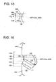
- the posture of the ball end mill 132 is changed by each area of 190, 192 and 194, as shown in Fig. 16 .
- areas from the area 154 via area 152 to area 150 are processed while making swirl revolution of the ball end mill 132 (refer to Fig. 3b ), in the area 190 the rotation axis of the ball end mill 132 is slightly inclined to the optical axis ((1) in Fig. 16 ), in the area 192 the rotation axis of the ball end mill 132 is kept parallel to the optical axis ((2) in Fig. 16 ), and in the area 190 the rotation axis of the ball end mill 132 is slightly inclined again to the optical axis ((3) in Fig. 14 ).
Landscapes
- Engineering & Computer Science (AREA)
- Mechanical Engineering (AREA)
- Health & Medical Sciences (AREA)
- Manufacturing & Machinery (AREA)
- Ophthalmology & Optometry (AREA)
- Mining & Mineral Resources (AREA)
- Milling Processes (AREA)
- Moulds For Moulding Plastics Or The Like (AREA)
Abstract
Description
- The present invention relates to a cutting tool according to the preamble of
claim 1 and a method for manufacturing a molding die according to the preamble of claim 6. An example of such a cutting tool is known fromJP 2005-342805 -
- Patent Document 1: Japanese Patent No.
3926380B - Conventionally, in a field of manufacturing optical lenses, a technology has been studies to obtain a high heat-resistant lens by providing a lens section made of hardening resin on a glass plate (for example, refer to Patent Document 1). As an example of the manufacturing method of optical lens applying this technology, proposed is a method where a so-called "wafer lens" is formed which is provided with optical members made of hardening resin on the surface of glass plate, and after that the glass plate is cut by each lens section.
- In cases of manufacturing a resin-made lens section of wafer lens or its resin-made transfer mold, a metallic molding die is generally used. As an example of manufacturing the molding die, there is a method of forming a circular concave or convex by making swirl revolution while rotating of a ball end mill with respect to the subject to be cut. Specifically, while rotating a cutting blade provided at an end of a shank section of the ball end mill, the cutting blade is directly made contact to the subject material to cut it.
- However, in cases of simply executing the cutting by the above way, minute imbricate recesses and protrusions (see
Fig. 10a ) or machined flaws (Fig. 10a ) are formed according to the trajectory of swirling revolution of the ball end mill, which prevent the formation of smooth curved surface. - Further, in the method of forming circular concave or convex by making swirling revolutions while rotating of a ball end mill with respect to the subject material, although the cutting blade provided at the edge of ball end mill basically contact the subject to be cut while rotating, the rotation center part of the cutting blade contacts the subject to be cut substantially with the state of no rotation. In this case in the part where the rotation center of the cutting blade passed on the subject material, machined flaws are formed in such a manner that the subject material is dragged and scuffed accompanying to the movement of the ball end mill (see
Fig. 9b ). - By examining the problem of minute imbricate recesses and protrusions, the inventers found out that due to the structure of the ball end mill, although the cutting blade is provided at the tip of the shank section, since the cutting blade is brazed on a supporting member which supports and fixes the cutting blade, and the supporting member is connected to the shank section (since the cutting blade is attached on the shank section via the supporting member), a void is formed between the shank section and the supporting member/cutting blade, and this void causes the vibration of the cutting blade. Namely, the inventors found out that although the cutting blade is arranged on the rotation axis of the ball end mill, during the movement of the ball end mill, the cutting blade swings between the position on the rotation axis and the position dislocated from the axis, and causes to form the minute recesses and protrusions.
- Further, the present inventors examined the problem of machined flaws being formed according to the trajectory of swirling revolution of the ball end mill, and found out that since the cutting blade provided at the edge of ball end mill contacts the subject material at the rotation center part of the cutting blade with the state of substantially no rotation, and further, since the rotation center part is inflected, the rotational center part of the cutting blade drags and scuffs the subject material accompanying to the movement of the ball end mill, and machined flaws are formed on the surface of concave or convex.
- Therefore, a main objective of the present invention is to provide a cutting tool and a method for manufacturing a molding die that prevent the machined flaws being formed on the subject material, and enable the formation of the smooth curved surface of concave or convex.
- In order to solve the abovementioned problem, the present invention provides a cutting tool including the features of
claim 1. Preferred embodiments of the cutting tool are defined in the dependent claims. This cutting tool has
a cutting blade;
a shank section; and
a supporting member for supporting and fixing the cutting blade, the cutting blade being fixed on one end of the supporting member, and the other end of the supporting member being fixed to the shank section,
wherein a void formed among the shank section, the cutting blade, and the supporting member is filled with a filling agent. - According to an other aspect of the present invention, provided is a use of such a cutting tool for cutting a subject material by making a swirling revolution of a cutting blade while rotating a part of the cutting blade about a rotation center part of the cutting blade as defined claim 5. Preferably the rotation center part of the cutting blade of the tool is a part of a circular are, and a radius r of the circular arc of the rotation center part satisfies the condition of: 0.05 ≤ r ≤ 5 µm.
- According to another aspect of the present invention, provided is a method for manufacturing a molding die, including the steps of claim 6.
- According to the present invention, there is provided a method for manufacturing a molding die, including the steps of:
- forming a convex or concave part by applying a rough processing to a subject material to be cut; and
- applying a finish processing to the convex or concave part by making swirling revolution of a ball end mill while rotating the ball end mill with respect to the convex or concave part,
- wherein in the step of applying the finish processing to the convex or concave part, with respect to a first area including an area perpendicular to the optical axis of the convex or concave part, a cutting work of the finish processing is executed by inclining a rotation axis of the ball end mill against the optical axis, and with respect to a second area adjacent to the first area, the cutting work is executed by making the rotation axis of the ball end mill parallel to the optical axis.
- Further, according to the present invention, provided is a method for manufacturing a molding die by a cutting work using a cutting tool of the invention
the method comprising the steps of: - forming a convex or concave part by applying a rough processing to a subject material to be cut; and
- applying a finish processing to the convex or concave part by making swirling revolution of a ball end mill while rotating the ball end mill with respect to the convex or concave part,
- wherein in the step of applying the finish processing to the convex or concave part, with respect to a first area including an area perpendicular to the optical axis of the convex or concave part, a cutting work of the finish processing is executed by inclining a rotation axis of the ball end mill against the optical axis, and with respect to a second area adjacent to the first area, the cutting work is executed by making the rotation axis of the ball end mill parallel to the optical axis.
- According to the present invention, since the void among the shank section, cutting blade and the supporting blade is filled with the filling agent, the vibration caused by the rotation of cutting tool is suppressed to enable the formation of a smooth curved surface of concave or convex of the subject.
- Further, according to the present invention, since the cutting blade is arranged on the rotation axis, and the rotation center part of the cutting blade has a curvature, the rotation center part of the cutting blade draws a swirling trajectory while smoothly contacting the subject material. Therefore, the rotation center part of cutting blade is prevented from being dragged and scuffed by the swirling movement, which prevents the formation ofmachined flaws on the subject material.
- Further, according to the present invention, since the rotation center of the ball end mill has no rotational velocity and has no cutting ability. Therefore, in the area perpendicular to the optical axis of the concave or convex part of the subject material, the rotation axis of the ball end mill is inclined against the optical axis. As the result, generation of machined flaws on the subject can be prevented.
-
-
Fig. 1 is a perspective view showing an outline structure of concave molding die. -
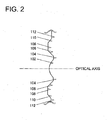
Fig. 2 is a section view taken along a line I-I ofFig. 1 . -
Fig. 3a is a perspective view andFig. 3b is a partially enlarged view respectively showing an outline structure of the cutting device. -
Fig. 4a is a perspective view andFig. 4b is a partially enlarged view respectively showing an outline structure of a variant example of the cutting device. -
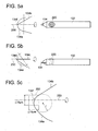
Fig. 5a is a plan view andFig. 5b is a side view respectively showing an outline structure of a ball end mill. -
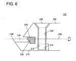
Fig. 6 is a side section view showing an outline structure of the tip part of the ball end mill. -
Fig. 7 shows schematic diagrams illustrating over time a method for manufacturing a molding die. -
Fig. 8 is a drawing schematically showing a mode of finish processing. -
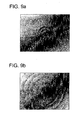
Figs. 9a and 9b are microscopic photo images showing the concave part of the molding die after the finish processing, which compare the surface figures caused by the difference of cutting blade figures. -
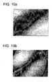
Figs. 10a and 10b are microscopic photo images showing the concave part of the molding die after the finish processing, which show the surface figures in a case where the void in the ball end mill is not filled with the filling agent. -
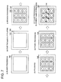
Figs. 11a and 11b are plan views schematically illustrating modes of an alignment mark. -
Fig. 12 is a perspective view showing an outline structure of convex molding die. -
Fig. 13 is a section view taken along a line II-II ofFig. 12 . -
Fig. 14 is a drawing schematically showing a mode of finish processing. -
Fig. 15 is a drawing schematically showing a principle of finish processing. -
Fig. 16 is a section view taken along a line II-II ofFig. 12 . - Hereinafter, the preferred embodiment of the present invention will be explained referring to the drawings.
- As shown in
Fig. 1 , molding die 100 has approximately a rectangular figure, and on its surface, multiple concave portions 102 (cavities) are formed. The molding die 100 is an example of the molding die for array lens, which is preferably utilized particularly for molding a resin lens section of wafer lens, and further usable for manufacturing its resin made transfer molding die. - As shown in
Fig. 2 , which is a detailed section view of one block where theconcave portion 102 is formed, in the periphery ofconcave portion 102,flat surface part 104,slant surface part 106,flat surface part 108,slant surface part 110, andflat surface part 112, are sequentially formed concentrically with a center of theconcave portion 102. The surface of center part of theconcave portion 102 is configured to be perpendicular to an optical axis (the axis of an optical system produced by molding from the molding die 100). - The figure of molding die 100 is not restricted to the approximate rectangular figure, but may be approximate cylindrical or divided cylindrical figure.
- As shown in
Fig. 3a , cuttingdevice 120A has aplaten 122. On theplaten 122, astage 124 having perpendicular axes and swirling axis is provided. Thestage 124 is configured to be movable in X axis direction and Y axis direction as well as turnable along B axis direction. On thestage 124, aspindle 126 is provided. On theplaten 122, afixing tool 128 for fixing a subject material (work material) is provided. On theplaten 122, thespindle 126 and thefixing tool 128 are arranged to face with each other. The fixingtool 128 is configured to be movable in Y axis direction, and thespindle 126 and the subject material are relatively movable. - The
spindle 126 has a built-in spindle motor. As shown inFig. 3b , at themain shaft 130 of the spindle motor, aball end mill 132 is provided. The ball end mill is an example of cutting tools. - In order to process the optical surface in high precision, the
spindle 126 provided with theball end mill 132 is preferably configured to have an air bearing. As the power source for rotating the spindle motor, there are a spindle motor system built-in with a spindle motor, and an air turbine system supplying high pressure air. As for said power source, it is preferable to adopt the spindle motor system for ensuring high stiffness. - As shown in
Figs. 5a and 5b , at the tip part of theball end mill 132, acutting blade 134 is fixed. The cutting blade is a diamond tip configured with a single-crystal diamond. - As shown in
Fig. 5a , viewing with a planar view, thecutting blade 134 has acircular arc section 134a and alinear section 134b. And viewing with side view, as shown inFig. 5b , thecutting blade 134 haslinear sections circular arc section 134a, theliner arc sections 134b-134e correspond to ridge lines where each plain surface configuring thecutting blade 134 meet. - In the
spindle 126, when the spindle motor rotates, in conjunction with its rotation thecutting blade 134 rotates while drawing a hemispheric trajectory (refer to dashed double dotted lines inFigs. 5a and 5b ). In this case a contact point of thecircular arc section 134a, theliner arc sections rotation center part 134f of thespindle 126, and therotation center part 134f does not substantially rotate. - As shown in
Fig. 5a , thecutting blade 134 is arranged on a rotation axis 250 (rotation center axis) of theball end mill 132. In thecutting blade 134, therotation center part 134f is arranged on therotation axis 250. - When viewing the
rotation center part 134f with an enlarged plan view, as shown inFig. 5c , therotation center part 134f has a curvature. - In detail, the
rotation center part 134f is configured with a part of circular arc, and radius r of said circular arc satisfies the conditions of: 0.05 ≤ r ≤ 5 µm. The radius r is set to be not less than 0.05 µm due to the reason that making less than 0.05 µm is difficult for manufacturing, and r is set to be not more than 5 µm due to the reason that an excellent molding die 100 exceeding a practical use level can be produced by machining the subject with this condition. - Further,
rotation center part 134f resides within asquare region 260 having not greater than 10 µm height and 10 µm width. Also, in this case where therotation center part 134f resides inside thesquare region 260, the excellent molding die 100 exceeding a practical use level can be produced by machining the subject. - The
rotation center part 134f may be configured, for example, with a part of an ellipsoidal arc or with just a curved line, viewing with the plan view. Just a cubed line means a curved line not configuring the circular arc, and said curved line may partially include a linear line. - The tip part of
ball end mill 132 will be further described in detail. - As shown in
Fig. 6 , said tip part is configured with ashank section 200 made of super-hard alloy (or cemented carbide). In theshank section 200, a through-hole 202 for screw insertion is formed. - On the
shank section 200, a supportingmember 210 for supporting and fixing thecutting blade 134 is disposed. Also in the supportingmember 210, a through-hole 212 for screw insertion is formed. - On a tip end portion of the supporting
member 210, thecutting blade 134 is brazed and fixed. As described above, thecutting blade 134 is arranged such that therotation center part 134f matches to therotation axis 250 of theball end mill 132. - The through-
hole 202 of theshank section 200 communicates with the through-hole 212 of the supporting member. Into these through-holes screw 220 is inserted and screwed to fix the supportingmember 210 to theshank section 200. Althoughscrew 220 is inserted from theshank section 200 toward the supportingmember 210, it may be inserted in opposite direction (the direction from the supportingmember 210 toward the shank section 200). At the tip part ofball end mill 132, thecutting blade 134 is configured to be fixed to theshank section 200 through the supportingmember 210. - In the area enclosed by the
shank section 200, supportingmember 210, and thecutting blade 134, avoid 230 is generated. In thevoid 230, a fillingagent 240 is filled. - As the filling
agent 240, a wax, a solder, a resin adhesive, and the like are used. The resin adhesive may be either a photo-curable resin or a thermo-setting resin. - Basically, the filling
agent 240 is coated or injected before the supporting member 210 (with the cutting blade 314) is disposed on theshank section 200, and after that the supportingmember 210 is attached. In case of using, as the fillingagent 240, a material having fluidity such as the adhesive, the material may be injected into the void 230 after attaching the supportingmember 210 onto theshank section 200. - In replace to the
cutting device 120A ofFig. 3a , thecutting device 120B ofFig. 4a can be utilized. - As shown in
Fig. 4a , in thecutting device 120B, the spindle 126 (of ball end mill 132) is turnable also in A axis direction and C axis direction. Each rotation axis of A axis, B axis and C axis is perpendicular to each other. The other configurations of thecutting device 120B are same as those of thecutting device 120A (refer toFig. 4b ). - According to the
cutting device 120B, the posture of theball end mill 132 can be controlled such that a normal line on a blade tip profile line at any arbitral point of the tip blade (cutting blade 134) and a normal line of the processing surface become parallel with each other. As the result, the processing can be executed at one point of the tip of blade tool (cutting blade 134), which can suppress an influence of tip profile error of the blade tool against a processed (machined) figure. - As shown in
Fig. 7 , the molding die 100 is manufactured mainly through processes of (a) - (g) below: - (a) Preparing a
subject material 140, and applying a blank processing to a prescribed area of the subject material; - (b) Applying an electroless Ni-P (Nickel-Phosphorous) plating at the prescribed area on the
subject material 140 to form a platedlayer 142; - (c) Applying a rough processing, by using a general purpose machining center, to the surface (plated layer 142) of the
subject material 140 to form an original form (concave or convex) of aconcave part 102 and the like; - (d) Polishing the surface of the
subject material 140 after the rough processing, to make a smooth surface; - (e) Applying a finish processing to the
concave part 102 by using a diamond cutting blade; and - (f) Applying a plane processing on the surface of the
subject material 140 to form a reference surface, and forms alignment marks on the reference surface. - The reference surface is a surface to be a reference in case of adjusting a height position to the other material.
- The
alignment mark 144 is use for position adjustment to the other material. - Depending on the surface condition of the processing surface (reference surface), polishing is executed after the processes of (e) and (f) to make the surface smooth. (g) Washing the
subject material 140 to remove processing debris, forming SiO2 layer on the surface of thesubject material 140, and coating a release agent. - SiO2 layer functions as a ground in case of coating the release agent. SiO2 layer is formed by any of evaporation, CVD or spattering processing. In order to form the SiO2 layer with uniform thickness, the DVD processing is preferable.
- The release agent is a material for making the release of a mold easy from the molding die 100.
- In the above description, as the process (c), the process of rough processing by the machining center to form the concave or convex part is provided, however, the rough processing is not restricted to said method but may be processed by other method. Therefore, the present invention is not restricted to the processing method or the cutting tool premising the rough processing by the use of the cutting tool.
- In the process (e), the
cutting device 120A is basically used. - As shown in
Fig. 3b , by activating the spindle motor of thespindle 126,ball end mill 132 is rotated with high speed. Further, by cooperative operation of moving thestage 124 in X axis direction and Z axis direction and moving thefixing tool 128 in Y axis direction, theball end mill 132 is allowed to make swirl revolution. Namely, by making swirl revolutions of the ball end mill while rotating the ball end mill, the finish processing of the surface ofconcave part 102 is executed. - In this case, as shown in
Fig. 8 , from the mostoutside area 154 viaarea 152 tocentral area 150, the ball end mill swirls and contacts while being rotated with keeping parallel state to the optical axis, to execute the processing onto theconcave part 102 and all or part of theplane surface part 104. - The
area 150 is a central part of theconcave part 102, and includes an area perpendicular to the optical axis. - The
area 152 is a peripheral part of theconcave part 102, and is adjacent to thearea 150. - The
area 154 is all or part of theplane surface part 104, and adjacent to thearea 152. - Here, in the case where the
rotation center part 134f of thecutting blade 134 is inflected (as sown with dotted line inFig. 5c ), therotation center part 134f without substantial rotation is dragged and scuffed by the swirling movement of thespindle 162 to cause concavo-convex machined flaws as shown inFig. 9a . - In contrast, according to the present embodiment, since the
rotation center part 134f has a curvature, therotation center part 134f draws the trajectory while smoothly contacting theconcave part 102, thus even therotation center part 134f contacts theconcave part 102, the machined flaw is not generated (or, even if the machined flaw is generated, its concavo-convex height is small). Therefore, as shown inFig. 9b , a smooth curved surface can be formed in theconcave part 102. - Also in the case of using the
cutting device 120A, since therotation center part 134f has a curvature and smoothly contacts theconcave part 102, the operation of inclining therotation center part 134f against theconcave part 102 by moving thespindle 126 in B axis direction is not necessary. - Further, in cases of not filling the filling
agent 240 to thevoid 230 ofball end mill 132, rotation movement of the ball end mill is transmitted to thecutting blade 134 via the supportingmember 210 to cause vibrations of thecutting blade 134, thus as shown inFig. 10a , minute imbricate recesses and protrusions are formed in theconcave part 102. - In contrast, according to the present embodiment, since the filling agent is filled in the
void 230 of theball end mill 132, transmission of the rotational force of theball end mill 132 to the cutting blade is suppressed, and the vibration of the cutting blade is suppressed to enable the formation of smooth curved surface in theconcave part 102 as shown inFig. 10b . - As described above, in the case of manufacturing an optical system (molding) by transferring the figure of the
concave part 102 of the molding die 100, quality of the optical surface of the optical system can be improved, and in case of using the optical system as an image capturing lens, generation of ghost images can be suppressed. - In the process (e), the
cutting device 120B can be also used. - Also in the case of using the
cutting device 120B, similarly to the case of using thecutting device 120A, by activating the spindle motor of thespindle 126, theball end mill 132 is rotated in high speed. In addition, by cooperative operation of moving thestage 124 in X axis direction and Z axis direction and moving thefixing tool 128 in Y axis direction, theball end mill 132 is allowed to make swirl revolution with respect to thesubject material 140. - At this time, while turning the ball end mill further in A axis and C axis directions, the ball end mill is swirled to execute the processing at a single point of the cutting blade tool (cutting blade 134) for finish processing of the surface of the
concave part 102. - Also in the process (f), the
cutting device 12A or 120B is used. - In this case, by replacing the
ball end mill 132 with a square end mill, the square end mill is swirled while rotating to execute a planer processing on surfaces of the flat surface parts 104 (remaining area excluding the area having been executed the finish processing), 108 and 112. As the result, theflat surface parts - The square end mill is a tool whose cutting blade profile draws a trajectory of cylinder or frustum of a cone, at the time of rotating the end mill.
- In the process (f), replacing with the square end mill, a radius end mill may be used whose cutting blade is R-shaped in part. Obviously, the ball end mill may be used successively to the process (e) for the planer processing.
- After that, as shown in
Fig. 11a , a cross-shaped alignment mark 144 (groove) having a prescribed line width is formed in theflat surface part 112. For the formation of thealignment mark 144, the square end mill, the ball end mill, or a cutting blade having a planer sharp edge cutting blade is relatively moved with linear movement. The intersection point of each center line in vertical and lateral line widths can be used for the position alignment with other material. - In the process (f),
alignment mark 146 shown inFig. 11b may be formed. Thealignment mark 146 is configured with overlappingcross-shaped grooves groove 146a and thegroove 146b are slightly displaced with each other, and the depth ofgroove 146a is less than the depth ofgroove 146b. Thus, between thegroove 146a and thegroove 146b, a step is formed, and the width of the step can be utilized for the position alignment with other materials. - Shape of the
alignment mark 146 may be, other than cross-shaped, circler or a square and the like. As long as being able to work out the prescribed position of thealignment mark 146, its shape is not restricted. - As shown in
Fig. 12 , - As shown in
Fig. 12 , molding die 180 has approximately a rectangular figure, and on its surface, multiple convex portions 182 (core) are formed. The molding die 180 is an example of the molding die for array lens. - As shown in
Fig. 13 , which is a detailed section view of one block where theconvex portion 182 is formed, in the periphery ofconvex portion 182,flat surface part 184,flat surface part 184 is formed concentrically with a center of theconvex portion 182. The surface of center part of theconvex portion 182 is configured to be perpendicular to an optical axis. - The figure of molding die 180 is not restricted to the approximate rectangular figure, but may be approximate cylindrical or divided cylindrical figure.
- The manufacturing method of the molding die 180 is similar to the manufacturing method of the molding die 100, except differences described below.
- In the process (e), as shown in
Fig. 13 , from the mostoutside area 194 viaarea 192 tocentral area 190, the ball end mill swirls and contacts the subject while being rotated with keeping parallel state to the optical axis, to execute the processing onto theconvex part 182 and all or part of theflat surface part 184. - The
area 190 is a central part of theconvex part 182, and includes an area perpendicular to the optical axis. - The
area 192 is a peripheral part of theconvex part 182, and is adjacent to thearea 190. - The
area 194 is all or part of theflat surface part 184, and adjacent to thearea 192. - As a variant example of the above described process (e) (finish processing of
concave part 102 by using the diamond cutting blade), the posture of theball end mill 132 could be changed by each area of 150,152,154, as shown inFig. 14 . - "The area including an area vertical to the optical axis" is defined as an area where, when the rotation axis of the
ball end mill 132 is inclined against the optical axis by a prescribed angle as described later, the dislocated rotation angle becomes not to interfere with the processing surface of theconcave part 102, and at least an area including a region ranging to the point where the angle, between a line perpendicular to the displaced rotation axis of the ball end mill from the optical axis of theconcave part 102 and a tangent line at the cross point of the inclined rotation axis line and the surface forming theconcave part 102, becomes other than zero degree (since in zero degree, the center of rotation axis of the inclinedball end mill 132 is still in contact relation to the processing surface of the concave part 102). - In case of processing from the
area 154 viaarea 152 toarea 150 while making swirl revolution of the ball end mill 132 (refer toFig. 3b ), in thearea 154 the rotation axis of theball end mill 132 is slightly inclined to the optical axis ((1) inFig. 14 ), in thearea 152 the rotation axis of theball end mill 132 is kept parallel to the optical axis ((2) inFig. 14 ), and in thearea 150 the rotation axis of theball end mill 132 is slightly inclined again to the optical axis ((3) inFig. 14 ). - In case of changing the posture of the
ball end mill 132 from thearea 154 to thearea 152 or from thearea 152 to thearea 150, it is preferable to complete the posture change by one loop of the swirling revolution of theball end mill 132. - Further, it is preferable to make swirl revolution of the
ball end mill 132 with a visual angle of 10 - 90% of the inclination angle of the ball end mill which is an inclined angle at the time of attaching theball end mill 132. - The posture change of the
ball end mill 132 is conducted based on the following principle (refer toFig. 15 ). - In cases where the rotation axis of the
ball end mill 132 is kept to be inclined to the optical axis, in acertain area 164 of theconcave part 102 dislocated from the optical axis, therotation center part 134f contacts the surface and is dragged and scuffed by the swirling movement of thespindle 162, while therotation center part 134f does not contact itsperipheral areas - Therefore, by changing the posture of the
ball end mill 132 in the area 170 between thearea 160 and thearea 164, therotation center part 134f can be prevented from being dragged and scuffed in thearea 160 and thearea 164. - In case of transferring the posture of the
ball end mill 132 from the state of being parallel to the state of being inclined to the optical axis, therotation center part 134f does not contact theconcave part 102, which enables to prevent the formation of machined flaw, as shown inFig. 9b . - Although, in case of changing the posture of the
ball end mill 132, a swirling center of thespindle 126 may be displaced to cause a processing error, this problem can be addressed by correcting the error. - As a variant example of manufacturing the convex molding die, the posture of the
ball end mill 132 is changed by each area of 190, 192 and 194, as shown inFig. 16 . - In the process (e), areas from the
area 154 viaarea 152 toarea 150 are processed while making swirl revolution of the ball end mill 132 (refer toFig. 3b ), in thearea 190 the rotation axis of theball end mill 132 is slightly inclined to the optical axis ((1) inFig. 16 ), in thearea 192 the rotation axis of theball end mill 132 is kept parallel to the optical axis ((2) inFig. 16 ), and in thearea 190 the rotation axis of theball end mill 132 is slightly inclined again to the optical axis ((3) inFig. 14 ). -
- 100: molding die
- 102: concave part (cavity)
- 104: flat surface part
- 106: slant surface part
- 108: flat surface part
- 110: slant surface part
- 112: flat surface part
- 120A, 120B: cutting device
- 122: platen
- 124: stage
- 126: spindle
- 128: fixing tool
- 130: main shaft (of a spindle motor)
- 132: ball end mill
- 134: cutting blade
- 134a: circular arc section
- 134b: linear section
- 134c, 134d, 134e: linear section
- 134f: rotation center part
- 140: subject material to be cut
- 142: plated layer
- 144, 146: alignment mark
- 146a, 146b: groove
- 150,152,154: area
- 180: molding die
- 182: convex part (core)
- 184: flat surface part
- 190, 192, 194: area
- 200: shank section
- 202: through-hole
- 210: supporting member
- 212: through-hole
- 220: screw
- 230: void (or space)
- 240: filling agent
- 250: rotation axis
- 260: square region
Claims (9)
- A cutting tool (132) comprising:a cutting blade (134);a shank section (200); anda supporting member (210) for supporting and fixing the cutting blade (134), the cutting blade (134) being fixed on one end of the supporting member (210), and the other end of the supporting member (210) being fixed to the shank section (200),wherein a void (230) is formed among the shank section (200), the cutting blade (134), and the supporting member (210), characterised in that the void (230) is filled with a filling agent (240).
- The cutting tool (132) described in claim 1, wherein the filling agent (240) is a wax, a solder, or a resin adhesive.
- The cutting tool (132) described in claim 1 or 2,
wherein a rotation center part (134f) of the cutting blade (134) is a part of a circular arc, and a radius r of the circular arc of the rotation center part (134f) satisfies the condition of: 0.05 ≤ r ≤ 5µm. - The cutting tool (132) described in claim 3, wherein the rotation center part (134f) is within a square range having sides of 10 µm.
- Use of a cutting tool (132) as defined in claim 3 or 4 for cutting a subject material (140) by making a swirling revolution of the cutting blade (134) while rotating a part of the cutting blade (134) about the rotation center part (134f) of the cutting blade (134).
- A method for manufacturing a molding die (100) by a cutting work using a cutting tool (132) as defined in any one of claims 1 to 4,
the method comprising the steps of:forming a convex or concave part (102) by applying a rough processing to a subject material (140) to be cut; andapplying a finish processing to the convex or concave part (102) by making swirling revolution of the cutting tool (132) while rotating the cutting tool (132) with respect to the convex or concave part (102),wherein in the step of applying the finish processing to the convex or concave part (102), with respect to a first area including an area perpendicular to an optical axis of an optical system to be produced by molding from the convex or concave part (102), a cutting work of the finish processing is executed by inclining a rotation axis (250) of the cutting tool (132)against the optical axis, and with respect to a second area adjacent to the first area, the cutting work is executed by making the rotation axis (250) of the cutting tool (132)parallel to the optical axis. - The method for manufacturing a molding die (100) described in claim 6, wherein in the step of applying the finish processing, a plurality of the concave or convex part (102) are processed in an array arrangement.
- The method for manufacturing a molding die (100) described in claim 7, in case of changing a posture of the cutting tool (132)between the first area and the second area, the posture change is completed by a single loop of the swirling revolution of the cutting tool (132).
- The method for manufacturing a molding die (100) described in claim 8, wherein the cutting tool (132)is made swirling revolution with a visual angle of 10 - 90% of the inclination angle of the cutting tool (132) in the first area.
Applications Claiming Priority (4)
| Application Number | Priority Date | Filing Date | Title |
|---|---|---|---|
| JP2009254303 | 2009-11-05 | ||
| JP2009296598 | 2009-12-28 | ||
| JP2010006580 | 2010-01-15 | ||
| PCT/JP2010/068256 WO2011055627A1 (en) | 2009-11-05 | 2010-10-18 | Cutting tool, method for manufacturing molding die, and molding die for array lens |
Publications (3)
| Publication Number | Publication Date |
|---|---|
| EP2497592A1 EP2497592A1 (en) | 2012-09-12 |
| EP2497592A4 EP2497592A4 (en) | 2013-03-20 |
| EP2497592B1 true EP2497592B1 (en) | 2013-11-20 |
Family
ID=43969867
Family Applications (1)
| Application Number | Title | Priority Date | Filing Date |
|---|---|---|---|
| EP10828187.4A Not-in-force EP2497592B1 (en) | 2009-11-05 | 2010-10-18 | Cutting tool, method for manufacturing molding die |
Country Status (6)
| Country | Link |
|---|---|
| US (1) | US20120207869A1 (en) |
| EP (1) | EP2497592B1 (en) |
| JP (1) | JPWO2011055627A1 (en) |
| CN (1) | CN102712053A (en) |
| DK (1) | DK2497592T3 (en) |
| WO (1) | WO2011055627A1 (en) |
Families Citing this family (14)
| Publication number | Priority date | Publication date | Assignee | Title |
|---|---|---|---|---|
| JP5156990B1 (en) * | 2011-11-22 | 2013-03-06 | ナルックス株式会社 | Mold processing method |
| EP2915614B1 (en) * | 2012-10-31 | 2020-09-02 | Makino Milling Machine Co., Ltd. | Machine tool control device and machine tool |
| FR3003490B1 (en) * | 2013-03-25 | 2015-05-22 | Palumbo Ind | TOOL AND METHOD FOR MILLING A METAL PIECE |
| CN104117832B (en) * | 2014-07-15 | 2016-08-24 | 厦门理工学院 | A kind of manufacture method of packaged lens mould |
| CN104654781A (en) * | 2015-01-29 | 2015-05-27 | 吴传涛 | Temperature control regulator of push plate furnace |
| JP6637499B2 (en) * | 2015-06-29 | 2020-01-29 | 兼房株式会社 | Dimple processing method by milling and milling |
| JP2017094467A (en) * | 2015-11-26 | 2017-06-01 | 住友電工ハードメタル株式会社 | Rotary tool |
| NL2016689B1 (en) * | 2016-04-28 | 2017-11-20 | Anteryon Wafer Optics B V | Replication tool |
| US10702931B2 (en) * | 2016-05-19 | 2020-07-07 | Kanefusa Kabushiki Kaisha | Dimple processing method using rotary cutting tool |
| JP6278170B1 (en) * | 2016-08-26 | 2018-02-14 | 三菱日立ツール株式会社 | Cutting insert and cutting edge exchangeable rotary cutting tool |
| KR102133164B1 (en) | 2016-08-26 | 2020-07-13 | 미츠비시 히타치 쓰루 가부시키가이샤 | Cutting inserts and indexable rotary cutting tools |
| EP3583453A4 (en) * | 2017-02-14 | 2021-03-10 | 3M Innovative Properties Company | Security articles comprising groups of microstructures made by end milling |
| CN108296493A (en) * | 2018-01-16 | 2018-07-20 | 广东工业大学 | A kind of teeth processing route generating method of fine turning lathe processing Fresnel micro structure array |
| JP2024013853A (en) * | 2022-07-21 | 2024-02-01 | デクセリアルズ株式会社 | End mill, method for manufacturing metallic mold for fabricating microlens, and device for manufacturing metallic mold for fabricating microlens |
Family Cites Families (13)
| Publication number | Priority date | Publication date | Assignee | Title |
|---|---|---|---|---|
| US2378094A (en) * | 1943-06-18 | 1945-06-12 | Dominion Diamond Cutting Compa | Metal boring or cutting tool |
| US3025726A (en) * | 1960-07-11 | 1962-03-20 | Super Cut | Method of mounting diamonds in tool shanks and other holders |
| JPS62292309A (en) * | 1986-06-09 | 1987-12-19 | Fanuc Ltd | Pocket working method |
| JPH068028A (en) * | 1991-10-04 | 1994-01-18 | Eisuke Yokoyama | Crisscross pattern solid finishing machine structure |
| JP3249081B2 (en) * | 1997-12-29 | 2002-01-21 | キヤノン株式会社 | Diffraction surface shape and optical element manufacturing method |
| JP2001121337A (en) * | 1999-10-19 | 2001-05-08 | Kanefusa Corp | Tipped rotary cutting tool |
| JP2005212015A (en) * | 2004-01-28 | 2005-08-11 | Fuji Photo Film Co Ltd | Cutting tool |
| JP2005342805A (en) * | 2004-05-31 | 2005-12-15 | Ricoh Co Ltd | Radius end mill and cutting method using it |
| JP2007090517A (en) * | 2005-09-05 | 2007-04-12 | Sanwa Kenma Kogyo Kk | Rotating tool and coating film removing method |
| JP5119581B2 (en) * | 2005-09-14 | 2013-01-16 | 株式会社タンガロイ | Ball end mill |
| JP3926380B1 (en) | 2006-12-07 | 2007-06-06 | マイルストーン株式会社 | Imaging lens |
| CN201316833Y (en) * | 2008-11-12 | 2009-09-30 | 郑黄铮 | Annularly-coated milling cutter |
| JP4896117B2 (en) * | 2008-12-01 | 2012-03-14 | 京セラ株式会社 | Cutting tools |
-
2010
- 2010-10-18 EP EP10828187.4A patent/EP2497592B1/en not_active Not-in-force
- 2010-10-18 US US13/503,830 patent/US20120207869A1/en not_active Abandoned
- 2010-10-18 WO PCT/JP2010/068256 patent/WO2011055627A1/en active Application Filing
- 2010-10-18 JP JP2011539328A patent/JPWO2011055627A1/en active Pending
- 2010-10-18 CN CN2010800485816A patent/CN102712053A/en active Pending
- 2010-10-18 DK DK10828187.4T patent/DK2497592T3/en active
Also Published As
| Publication number | Publication date |
|---|---|
| EP2497592A1 (en) | 2012-09-12 |
| DK2497592T3 (en) | 2014-02-03 |
| JPWO2011055627A1 (en) | 2013-03-28 |
| CN102712053A (en) | 2012-10-03 |
| WO2011055627A1 (en) | 2011-05-12 |
| EP2497592A4 (en) | 2013-03-20 |
| US20120207869A1 (en) | 2012-08-16 |
Similar Documents
| Publication | Publication Date | Title |
|---|---|---|
| EP2497592B1 (en) | Cutting tool, method for manufacturing molding die | |
| US7556456B2 (en) | Mono crystalline diamond cutting tool for ultra precision machining | |
| TWI359711B (en) | Raster cutting technology for ophthalmic lenses | |
| CN102490103B (en) | Meniscus lens and processing method therefor | |
| JP3161423U (en) | Grinding tool | |
| JP2007181882A (en) | Machining method for transfer optical surface, forming die for optical element and optical element | |
| JP2010142890A (en) | Method of correcting outer circumferential shape of cutting member, dresser board, and cutting device | |
| US7793403B2 (en) | Manufacturing method of optical component or molding die therefor | |
| JP3879891B2 (en) | Offset rotary surface processing apparatus and method | |
| CN102947034A (en) | Cutting tool | |
| CN104802060B (en) | Tool for being polished processing to optical surface | |
| JP4670249B2 (en) | Processing apparatus, processing method, and diamond tool | |
| WO2011142372A1 (en) | Mold cutting method | |
| JP4374161B2 (en) | Cutting method of optical lens or its mold | |
| US20100035524A1 (en) | Method of producing optical element, and optical element | |
| JP2011011295A (en) | Fine recessed part working method and fine recessed part working machine | |
| JP2002361510A (en) | Milling method of fine recessed surface and its device | |
| US6238800B1 (en) | Lens and an optical apparatus with the lens | |
| JP2005342805A (en) | Radius end mill and cutting method using it | |
| JP2000052217A (en) | Tool and processing method | |
| WO2024018895A1 (en) | End mill, method for producing mold for creating microlens, and device for producing mold for creating microlens | |
| JP4882103B2 (en) | Drill thinning apparatus and thinning forming method | |
| JP2005144657A (en) | Monocrystal diamond end mill and cutting method of hard fragile material | |
| CN113579316A (en) | Ultrasonic auxiliary vibration processing method | |
| JPH07204922A (en) | End mill |
Legal Events
| Date | Code | Title | Description |
|---|---|---|---|
| PUAI | Public reference made under article 153(3) epc to a published international application that has entered the european phase |
Free format text: ORIGINAL CODE: 0009012 |
|
| 17P | Request for examination filed |
Effective date: 20120424 |
|
| AK | Designated contracting states |
Kind code of ref document: A1 Designated state(s): AL AT BE BG CH CY CZ DE DK EE ES FI FR GB GR HR HU IE IS IT LI LT LU LV MC MK MT NL NO PL PT RO RS SE SI SK SM TR |
|
| RAP1 | Party data changed (applicant data changed or rights of an application transferred) |
Owner name: KONICA MINOLTA ADVANCED LAYERS, INC. |
|
| DAX | Request for extension of the european patent (deleted) | ||
| A4 | Supplementary search report drawn up and despatched |
Effective date: 20130215 |
|
| RIC1 | Information provided on ipc code assigned before grant |
Ipc: B24B 13/04 20060101ALI20130211BHEP Ipc: G02B 3/00 20060101ALI20130211BHEP Ipc: B23C 3/16 20060101ALI20130211BHEP Ipc: B23C 5/10 20060101AFI20130211BHEP Ipc: B23B 27/06 20060101ALI20130211BHEP Ipc: B23C 9/00 20060101ALI20130211BHEP Ipc: B29C 33/38 20060101ALI20130211BHEP Ipc: B23B 27/20 20060101ALI20130211BHEP Ipc: B29L 11/00 20060101ALI20130211BHEP |
|
| GRAP | Despatch of communication of intention to grant a patent |
Free format text: ORIGINAL CODE: EPIDOSNIGR1 |
|
| RIC1 | Information provided on ipc code assigned before grant |
Ipc: B29L 11/00 20060101ALI20130516BHEP Ipc: B24B 13/04 20060101ALI20130516BHEP Ipc: B29C 33/38 20060101ALI20130516BHEP Ipc: B23C 3/16 20060101ALI20130516BHEP Ipc: B23C 9/00 20060101ALI20130516BHEP Ipc: B23C 5/10 20060101AFI20130516BHEP Ipc: G02B 3/00 20060101ALI20130516BHEP Ipc: B23B 27/20 20060101ALI20130516BHEP Ipc: B23B 27/06 20060101ALI20130516BHEP |
|
| INTG | Intention to grant announced |
Effective date: 20130531 |
|
| GRAS | Grant fee paid |
Free format text: ORIGINAL CODE: EPIDOSNIGR3 |
|
| GRAA | (expected) grant |
Free format text: ORIGINAL CODE: 0009210 |
|
| AK | Designated contracting states |
Kind code of ref document: B1 Designated state(s): AL AT BE BG CH CY CZ DE DK EE ES FI FR GB GR HR HU IE IS IT LI LT LU LV MC MK MT NL NO PL PT RO RS SE SI SK SM TR |
|
| REG | Reference to a national code |
Ref country code: GB Ref legal event code: FG4D |
|
| REG | Reference to a national code |
Ref country code: CH Ref legal event code: EP |
|
| REG | Reference to a national code |
Ref country code: AT Ref legal event code: REF Ref document number: 641281 Country of ref document: AT Kind code of ref document: T Effective date: 20131215 |
|
| REG | Reference to a national code |
Ref country code: IE Ref legal event code: FG4D |
|
| REG | Reference to a national code |
Ref country code: DE Ref legal event code: R096 Ref document number: 602010011989 Country of ref document: DE Effective date: 20140116 |
|
| REG | Reference to a national code |
Ref country code: DK Ref legal event code: T3 Effective date: 20140128 |
|
| REG | Reference to a national code |
Ref country code: NL Ref legal event code: VDEP Effective date: 20131120 |
|
| REG | Reference to a national code |
Ref country code: AT Ref legal event code: MK05 Ref document number: 641281 Country of ref document: AT Kind code of ref document: T Effective date: 20131120 |
|
| REG | Reference to a national code |
Ref country code: LT Ref legal event code: MG4D |
|
| PG25 | Lapsed in a contracting state [announced via postgrant information from national office to epo] |
Ref country code: NL Free format text: LAPSE BECAUSE OF FAILURE TO SUBMIT A TRANSLATION OF THE DESCRIPTION OR TO PAY THE FEE WITHIN THE PRESCRIBED TIME-LIMIT Effective date: 20131120 Ref country code: IS Free format text: LAPSE BECAUSE OF FAILURE TO SUBMIT A TRANSLATION OF THE DESCRIPTION OR TO PAY THE FEE WITHIN THE PRESCRIBED TIME-LIMIT Effective date: 20140320 Ref country code: NO Free format text: LAPSE BECAUSE OF FAILURE TO SUBMIT A TRANSLATION OF THE DESCRIPTION OR TO PAY THE FEE WITHIN THE PRESCRIBED TIME-LIMIT Effective date: 20140220 Ref country code: FI Free format text: LAPSE BECAUSE OF FAILURE TO SUBMIT A TRANSLATION OF THE DESCRIPTION OR TO PAY THE FEE WITHIN THE PRESCRIBED TIME-LIMIT Effective date: 20131120 Ref country code: LT Free format text: LAPSE BECAUSE OF FAILURE TO SUBMIT A TRANSLATION OF THE DESCRIPTION OR TO PAY THE FEE WITHIN THE PRESCRIBED TIME-LIMIT Effective date: 20131120 Ref country code: HR Free format text: LAPSE BECAUSE OF FAILURE TO SUBMIT A TRANSLATION OF THE DESCRIPTION OR TO PAY THE FEE WITHIN THE PRESCRIBED TIME-LIMIT Effective date: 20131120 Ref country code: SE Free format text: LAPSE BECAUSE OF FAILURE TO SUBMIT A TRANSLATION OF THE DESCRIPTION OR TO PAY THE FEE WITHIN THE PRESCRIBED TIME-LIMIT Effective date: 20131120 |
|
| PG25 | Lapsed in a contracting state [announced via postgrant information from national office to epo] |
Ref country code: LV Free format text: LAPSE BECAUSE OF FAILURE TO SUBMIT A TRANSLATION OF THE DESCRIPTION OR TO PAY THE FEE WITHIN THE PRESCRIBED TIME-LIMIT Effective date: 20131120 Ref country code: BE Free format text: LAPSE BECAUSE OF FAILURE TO SUBMIT A TRANSLATION OF THE DESCRIPTION OR TO PAY THE FEE WITHIN THE PRESCRIBED TIME-LIMIT Effective date: 20131120 Ref country code: AT Free format text: LAPSE BECAUSE OF FAILURE TO SUBMIT A TRANSLATION OF THE DESCRIPTION OR TO PAY THE FEE WITHIN THE PRESCRIBED TIME-LIMIT Effective date: 20131120 Ref country code: ES Free format text: LAPSE BECAUSE OF FAILURE TO SUBMIT A TRANSLATION OF THE DESCRIPTION OR TO PAY THE FEE WITHIN THE PRESCRIBED TIME-LIMIT Effective date: 20131120 Ref country code: RS Free format text: LAPSE BECAUSE OF FAILURE TO SUBMIT A TRANSLATION OF THE DESCRIPTION OR TO PAY THE FEE WITHIN THE PRESCRIBED TIME-LIMIT Effective date: 20131120 |
|
| PG25 | Lapsed in a contracting state [announced via postgrant information from national office to epo] |
Ref country code: PT Free format text: LAPSE BECAUSE OF FAILURE TO SUBMIT A TRANSLATION OF THE DESCRIPTION OR TO PAY THE FEE WITHIN THE PRESCRIBED TIME-LIMIT Effective date: 20140320 |
|
| PG25 | Lapsed in a contracting state [announced via postgrant information from national office to epo] |
Ref country code: EE Free format text: LAPSE BECAUSE OF FAILURE TO SUBMIT A TRANSLATION OF THE DESCRIPTION OR TO PAY THE FEE WITHIN THE PRESCRIBED TIME-LIMIT Effective date: 20131120 |
|
| REG | Reference to a national code |
Ref country code: DE Ref legal event code: R097 Ref document number: 602010011989 Country of ref document: DE |
|
| PG25 | Lapsed in a contracting state [announced via postgrant information from national office to epo] |
Ref country code: SK Free format text: LAPSE BECAUSE OF FAILURE TO SUBMIT A TRANSLATION OF THE DESCRIPTION OR TO PAY THE FEE WITHIN THE PRESCRIBED TIME-LIMIT Effective date: 20131120 Ref country code: CZ Free format text: LAPSE BECAUSE OF FAILURE TO SUBMIT A TRANSLATION OF THE DESCRIPTION OR TO PAY THE FEE WITHIN THE PRESCRIBED TIME-LIMIT Effective date: 20131120 Ref country code: RO Free format text: LAPSE BECAUSE OF FAILURE TO SUBMIT A TRANSLATION OF THE DESCRIPTION OR TO PAY THE FEE WITHIN THE PRESCRIBED TIME-LIMIT Effective date: 20131120 Ref country code: PL Free format text: LAPSE BECAUSE OF FAILURE TO SUBMIT A TRANSLATION OF THE DESCRIPTION OR TO PAY THE FEE WITHIN THE PRESCRIBED TIME-LIMIT Effective date: 20131120 |
|
| PLBE | No opposition filed within time limit |
Free format text: ORIGINAL CODE: 0009261 |
|
| STAA | Information on the status of an ep patent application or granted ep patent |
Free format text: STATUS: NO OPPOSITION FILED WITHIN TIME LIMIT |
|
| 26N | No opposition filed |
Effective date: 20140821 |
|
| REG | Reference to a national code |
Ref country code: DE Ref legal event code: R097 Ref document number: 602010011989 Country of ref document: DE Effective date: 20140821 |
|
| PG25 | Lapsed in a contracting state [announced via postgrant information from national office to epo] |
Ref country code: SI Free format text: LAPSE BECAUSE OF FAILURE TO SUBMIT A TRANSLATION OF THE DESCRIPTION OR TO PAY THE FEE WITHIN THE PRESCRIBED TIME-LIMIT Effective date: 20131120 |
|
| REG | Reference to a national code |
Ref country code: DE Ref legal event code: R119 Ref document number: 602010011989 Country of ref document: DE |
|
| REG | Reference to a national code |
Ref country code: DK Ref legal event code: EBP Effective date: 20141031 |
|
| PG25 | Lapsed in a contracting state [announced via postgrant information from national office to epo] |
Ref country code: LU Free format text: LAPSE BECAUSE OF FAILURE TO SUBMIT A TRANSLATION OF THE DESCRIPTION OR TO PAY THE FEE WITHIN THE PRESCRIBED TIME-LIMIT Effective date: 20141018 Ref country code: MC Free format text: LAPSE BECAUSE OF FAILURE TO SUBMIT A TRANSLATION OF THE DESCRIPTION OR TO PAY THE FEE WITHIN THE PRESCRIBED TIME-LIMIT Effective date: 20131120 |
|
| REG | Reference to a national code |
Ref country code: CH Ref legal event code: PL |
|
| GBPC | Gb: european patent ceased through non-payment of renewal fee |
Effective date: 20141018 |
|
| REG | Reference to a national code |
Ref country code: IE Ref legal event code: MM4A |
|
| PG25 | Lapsed in a contracting state [announced via postgrant information from national office to epo] |
Ref country code: LI Free format text: LAPSE BECAUSE OF NON-PAYMENT OF DUE FEES Effective date: 20141031 Ref country code: GB Free format text: LAPSE BECAUSE OF NON-PAYMENT OF DUE FEES Effective date: 20141018 Ref country code: CH Free format text: LAPSE BECAUSE OF NON-PAYMENT OF DUE FEES Effective date: 20141031 Ref country code: DE Free format text: LAPSE BECAUSE OF NON-PAYMENT OF DUE FEES Effective date: 20150501 |
|
| REG | Reference to a national code |
Ref country code: FR Ref legal event code: ST Effective date: 20150630 |
|
| PG25 | Lapsed in a contracting state [announced via postgrant information from national office to epo] |
Ref country code: IT Free format text: LAPSE BECAUSE OF FAILURE TO SUBMIT A TRANSLATION OF THE DESCRIPTION OR TO PAY THE FEE WITHIN THE PRESCRIBED TIME-LIMIT Effective date: 20131120 Ref country code: FR Free format text: LAPSE BECAUSE OF NON-PAYMENT OF DUE FEES Effective date: 20141031 |
|
| PG25 | Lapsed in a contracting state [announced via postgrant information from national office to epo] |
Ref country code: IE Free format text: LAPSE BECAUSE OF NON-PAYMENT OF DUE FEES Effective date: 20141018 Ref country code: DK Free format text: LAPSE BECAUSE OF NON-PAYMENT OF DUE FEES Effective date: 20141031 |
|
| PG25 | Lapsed in a contracting state [announced via postgrant information from national office to epo] |
Ref country code: SM Free format text: LAPSE BECAUSE OF FAILURE TO SUBMIT A TRANSLATION OF THE DESCRIPTION OR TO PAY THE FEE WITHIN THE PRESCRIBED TIME-LIMIT Effective date: 20131120 |
|
| PG25 | Lapsed in a contracting state [announced via postgrant information from national office to epo] |
Ref country code: BG Free format text: LAPSE BECAUSE OF FAILURE TO SUBMIT A TRANSLATION OF THE DESCRIPTION OR TO PAY THE FEE WITHIN THE PRESCRIBED TIME-LIMIT Effective date: 20131120 Ref country code: GR Free format text: LAPSE BECAUSE OF FAILURE TO SUBMIT A TRANSLATION OF THE DESCRIPTION OR TO PAY THE FEE WITHIN THE PRESCRIBED TIME-LIMIT Effective date: 20140221 Ref country code: CY Free format text: LAPSE BECAUSE OF FAILURE TO SUBMIT A TRANSLATION OF THE DESCRIPTION OR TO PAY THE FEE WITHIN THE PRESCRIBED TIME-LIMIT Effective date: 20131120 |
|
| PG25 | Lapsed in a contracting state [announced via postgrant information from national office to epo] |
Ref country code: HU Free format text: LAPSE BECAUSE OF FAILURE TO SUBMIT A TRANSLATION OF THE DESCRIPTION OR TO PAY THE FEE WITHIN THE PRESCRIBED TIME-LIMIT; INVALID AB INITIO Effective date: 20101018 Ref country code: MT Free format text: LAPSE BECAUSE OF FAILURE TO SUBMIT A TRANSLATION OF THE DESCRIPTION OR TO PAY THE FEE WITHIN THE PRESCRIBED TIME-LIMIT Effective date: 20131120 Ref country code: TR Free format text: LAPSE BECAUSE OF FAILURE TO SUBMIT A TRANSLATION OF THE DESCRIPTION OR TO PAY THE FEE WITHIN THE PRESCRIBED TIME-LIMIT Effective date: 20131120 |
|
| PG25 | Lapsed in a contracting state [announced via postgrant information from national office to epo] |
Ref country code: MK Free format text: LAPSE BECAUSE OF FAILURE TO SUBMIT A TRANSLATION OF THE DESCRIPTION OR TO PAY THE FEE WITHIN THE PRESCRIBED TIME-LIMIT Effective date: 20131120 |
|
| PG25 | Lapsed in a contracting state [announced via postgrant information from national office to epo] |
Ref country code: AL Free format text: LAPSE BECAUSE OF FAILURE TO SUBMIT A TRANSLATION OF THE DESCRIPTION OR TO PAY THE FEE WITHIN THE PRESCRIBED TIME-LIMIT Effective date: 20131120 |