EP2497445B1 - Valve and system - Google Patents
Valve and system Download PDFInfo
- Publication number
- EP2497445B1 EP2497445B1 EP12170873.9A EP12170873A EP2497445B1 EP 2497445 B1 EP2497445 B1 EP 2497445B1 EP 12170873 A EP12170873 A EP 12170873A EP 2497445 B1 EP2497445 B1 EP 2497445B1
- Authority
- EP
- European Patent Office
- Prior art keywords
- frame
- valve
- cover
- leaflet
- dimension
- Prior art date
- Legal status (The legal status is an assumption and is not a legal conclusion. Google has not performed a legal analysis and makes no representation as to the accuracy of the status listed.)
- Active
Links
Images


Classifications
-
- A—HUMAN NECESSITIES
- A61—MEDICAL OR VETERINARY SCIENCE; HYGIENE
- A61F—FILTERS IMPLANTABLE INTO BLOOD VESSELS; PROSTHESES; DEVICES PROVIDING PATENCY TO, OR PREVENTING COLLAPSING OF, TUBULAR STRUCTURES OF THE BODY, e.g. STENTS; ORTHOPAEDIC, NURSING OR CONTRACEPTIVE DEVICES; FOMENTATION; TREATMENT OR PROTECTION OF EYES OR EARS; BANDAGES, DRESSINGS OR ABSORBENT PADS; FIRST-AID KITS
- A61F2/00—Filters implantable into blood vessels; Prostheses, i.e. artificial substitutes or replacements for parts of the body; Appliances for connecting them with the body; Devices providing patency to, or preventing collapsing of, tubular structures of the body, e.g. stents
- A61F2/02—Prostheses implantable into the body
- A61F2/24—Heart valves ; Vascular valves, e.g. venous valves; Heart implants, e.g. passive devices for improving the function of the native valve or the heart muscle; Transmyocardial revascularisation [TMR] devices; Valves implantable in the body
- A61F2/2475—Venous valves
-
- A—HUMAN NECESSITIES
- A61—MEDICAL OR VETERINARY SCIENCE; HYGIENE
- A61B—DIAGNOSIS; SURGERY; IDENTIFICATION
- A61B90/00—Instruments, implements or accessories specially adapted for surgery or diagnosis and not covered by any of the groups A61B1/00 - A61B50/00, e.g. for luxation treatment or for protecting wound edges
- A61B90/39—Markers, e.g. radio-opaque or breast lesions markers
-
- A—HUMAN NECESSITIES
- A61—MEDICAL OR VETERINARY SCIENCE; HYGIENE
- A61F—FILTERS IMPLANTABLE INTO BLOOD VESSELS; PROSTHESES; DEVICES PROVIDING PATENCY TO, OR PREVENTING COLLAPSING OF, TUBULAR STRUCTURES OF THE BODY, e.g. STENTS; ORTHOPAEDIC, NURSING OR CONTRACEPTIVE DEVICES; FOMENTATION; TREATMENT OR PROTECTION OF EYES OR EARS; BANDAGES, DRESSINGS OR ABSORBENT PADS; FIRST-AID KITS
- A61F2/00—Filters implantable into blood vessels; Prostheses, i.e. artificial substitutes or replacements for parts of the body; Appliances for connecting them with the body; Devices providing patency to, or preventing collapsing of, tubular structures of the body, e.g. stents
- A61F2/02—Prostheses implantable into the body
- A61F2/24—Heart valves ; Vascular valves, e.g. venous valves; Heart implants, e.g. passive devices for improving the function of the native valve or the heart muscle; Transmyocardial revascularisation [TMR] devices; Valves implantable in the body
- A61F2/2409—Support rings therefor, e.g. for connecting valves to tissue
-
- A—HUMAN NECESSITIES
- A61—MEDICAL OR VETERINARY SCIENCE; HYGIENE
- A61F—FILTERS IMPLANTABLE INTO BLOOD VESSELS; PROSTHESES; DEVICES PROVIDING PATENCY TO, OR PREVENTING COLLAPSING OF, TUBULAR STRUCTURES OF THE BODY, e.g. STENTS; ORTHOPAEDIC, NURSING OR CONTRACEPTIVE DEVICES; FOMENTATION; TREATMENT OR PROTECTION OF EYES OR EARS; BANDAGES, DRESSINGS OR ABSORBENT PADS; FIRST-AID KITS
- A61F2/00—Filters implantable into blood vessels; Prostheses, i.e. artificial substitutes or replacements for parts of the body; Appliances for connecting them with the body; Devices providing patency to, or preventing collapsing of, tubular structures of the body, e.g. stents
- A61F2/02—Prostheses implantable into the body
- A61F2/24—Heart valves ; Vascular valves, e.g. venous valves; Heart implants, e.g. passive devices for improving the function of the native valve or the heart muscle; Transmyocardial revascularisation [TMR] devices; Valves implantable in the body
- A61F2/2412—Heart valves ; Vascular valves, e.g. venous valves; Heart implants, e.g. passive devices for improving the function of the native valve or the heart muscle; Transmyocardial revascularisation [TMR] devices; Valves implantable in the body with soft flexible valve members, e.g. tissue valves shaped like natural valves
- A61F2/2418—Scaffolds therefor, e.g. support stents
-
- A—HUMAN NECESSITIES
- A61—MEDICAL OR VETERINARY SCIENCE; HYGIENE
- A61F—FILTERS IMPLANTABLE INTO BLOOD VESSELS; PROSTHESES; DEVICES PROVIDING PATENCY TO, OR PREVENTING COLLAPSING OF, TUBULAR STRUCTURES OF THE BODY, e.g. STENTS; ORTHOPAEDIC, NURSING OR CONTRACEPTIVE DEVICES; FOMENTATION; TREATMENT OR PROTECTION OF EYES OR EARS; BANDAGES, DRESSINGS OR ABSORBENT PADS; FIRST-AID KITS
- A61F2/00—Filters implantable into blood vessels; Prostheses, i.e. artificial substitutes or replacements for parts of the body; Appliances for connecting them with the body; Devices providing patency to, or preventing collapsing of, tubular structures of the body, e.g. stents
- A61F2/02—Prostheses implantable into the body
- A61F2/24—Heart valves ; Vascular valves, e.g. venous valves; Heart implants, e.g. passive devices for improving the function of the native valve or the heart muscle; Transmyocardial revascularisation [TMR] devices; Valves implantable in the body
- A61F2/2412—Heart valves ; Vascular valves, e.g. venous valves; Heart implants, e.g. passive devices for improving the function of the native valve or the heart muscle; Transmyocardial revascularisation [TMR] devices; Valves implantable in the body with soft flexible valve members, e.g. tissue valves shaped like natural valves
-
- A—HUMAN NECESSITIES
- A61—MEDICAL OR VETERINARY SCIENCE; HYGIENE
- A61F—FILTERS IMPLANTABLE INTO BLOOD VESSELS; PROSTHESES; DEVICES PROVIDING PATENCY TO, OR PREVENTING COLLAPSING OF, TUBULAR STRUCTURES OF THE BODY, e.g. STENTS; ORTHOPAEDIC, NURSING OR CONTRACEPTIVE DEVICES; FOMENTATION; TREATMENT OR PROTECTION OF EYES OR EARS; BANDAGES, DRESSINGS OR ABSORBENT PADS; FIRST-AID KITS
- A61F2220/00—Fixations or connections for prostheses classified in groups A61F2/00 - A61F2/26 or A61F2/82 or A61F9/00 or A61F11/00 or subgroups thereof
- A61F2220/0008—Fixation appliances for connecting prostheses to the body
- A61F2220/0016—Fixation appliances for connecting prostheses to the body with sharp anchoring protrusions, e.g. barbs, pins, spikes
-
- A—HUMAN NECESSITIES
- A61—MEDICAL OR VETERINARY SCIENCE; HYGIENE
- A61F—FILTERS IMPLANTABLE INTO BLOOD VESSELS; PROSTHESES; DEVICES PROVIDING PATENCY TO, OR PREVENTING COLLAPSING OF, TUBULAR STRUCTURES OF THE BODY, e.g. STENTS; ORTHOPAEDIC, NURSING OR CONTRACEPTIVE DEVICES; FOMENTATION; TREATMENT OR PROTECTION OF EYES OR EARS; BANDAGES, DRESSINGS OR ABSORBENT PADS; FIRST-AID KITS
- A61F2220/00—Fixations or connections for prostheses classified in groups A61F2/00 - A61F2/26 or A61F2/82 or A61F9/00 or A61F11/00 or subgroups thereof
- A61F2220/0025—Connections or couplings between prosthetic parts, e.g. between modular parts; Connecting elements
- A61F2220/005—Connections or couplings between prosthetic parts, e.g. between modular parts; Connecting elements using adhesives
-
- A—HUMAN NECESSITIES
- A61—MEDICAL OR VETERINARY SCIENCE; HYGIENE
- A61F—FILTERS IMPLANTABLE INTO BLOOD VESSELS; PROSTHESES; DEVICES PROVIDING PATENCY TO, OR PREVENTING COLLAPSING OF, TUBULAR STRUCTURES OF THE BODY, e.g. STENTS; ORTHOPAEDIC, NURSING OR CONTRACEPTIVE DEVICES; FOMENTATION; TREATMENT OR PROTECTION OF EYES OR EARS; BANDAGES, DRESSINGS OR ABSORBENT PADS; FIRST-AID KITS
- A61F2220/00—Fixations or connections for prostheses classified in groups A61F2/00 - A61F2/26 or A61F2/82 or A61F9/00 or A61F11/00 or subgroups thereof
- A61F2220/0025—Connections or couplings between prosthetic parts, e.g. between modular parts; Connecting elements
- A61F2220/0066—Connections or couplings between prosthetic parts, e.g. between modular parts; Connecting elements stapled
-
- A—HUMAN NECESSITIES
- A61—MEDICAL OR VETERINARY SCIENCE; HYGIENE
- A61F—FILTERS IMPLANTABLE INTO BLOOD VESSELS; PROSTHESES; DEVICES PROVIDING PATENCY TO, OR PREVENTING COLLAPSING OF, TUBULAR STRUCTURES OF THE BODY, e.g. STENTS; ORTHOPAEDIC, NURSING OR CONTRACEPTIVE DEVICES; FOMENTATION; TREATMENT OR PROTECTION OF EYES OR EARS; BANDAGES, DRESSINGS OR ABSORBENT PADS; FIRST-AID KITS
- A61F2220/00—Fixations or connections for prostheses classified in groups A61F2/00 - A61F2/26 or A61F2/82 or A61F9/00 or A61F11/00 or subgroups thereof
- A61F2220/0025—Connections or couplings between prosthetic parts, e.g. between modular parts; Connecting elements
- A61F2220/0075—Connections or couplings between prosthetic parts, e.g. between modular parts; Connecting elements sutured, ligatured or stitched, retained or tied with a rope, string, thread, wire or cable
-
- A—HUMAN NECESSITIES
- A61—MEDICAL OR VETERINARY SCIENCE; HYGIENE
- A61F—FILTERS IMPLANTABLE INTO BLOOD VESSELS; PROSTHESES; DEVICES PROVIDING PATENCY TO, OR PREVENTING COLLAPSING OF, TUBULAR STRUCTURES OF THE BODY, e.g. STENTS; ORTHOPAEDIC, NURSING OR CONTRACEPTIVE DEVICES; FOMENTATION; TREATMENT OR PROTECTION OF EYES OR EARS; BANDAGES, DRESSINGS OR ABSORBENT PADS; FIRST-AID KITS
- A61F2230/00—Geometry of prostheses classified in groups A61F2/00 - A61F2/26 or A61F2/82 or A61F9/00 or A61F11/00 or subgroups thereof
- A61F2230/0002—Two-dimensional shapes, e.g. cross-sections
- A61F2230/0004—Rounded shapes, e.g. with rounded corners
- A61F2230/0013—Horseshoe-shaped, e.g. crescent-shaped, C-shaped, U-shaped
-
- A—HUMAN NECESSITIES
- A61—MEDICAL OR VETERINARY SCIENCE; HYGIENE
- A61F—FILTERS IMPLANTABLE INTO BLOOD VESSELS; PROSTHESES; DEVICES PROVIDING PATENCY TO, OR PREVENTING COLLAPSING OF, TUBULAR STRUCTURES OF THE BODY, e.g. STENTS; ORTHOPAEDIC, NURSING OR CONTRACEPTIVE DEVICES; FOMENTATION; TREATMENT OR PROTECTION OF EYES OR EARS; BANDAGES, DRESSINGS OR ABSORBENT PADS; FIRST-AID KITS
- A61F2250/00—Special features of prostheses classified in groups A61F2/00 - A61F2/26 or A61F2/82 or A61F9/00 or A61F11/00 or subgroups thereof
- A61F2250/0058—Additional features; Implant or prostheses properties not otherwise provided for
- A61F2250/0096—Markers and sensors for detecting a position or changes of a position of an implant, e.g. RF sensors, ultrasound markers
- A61F2250/0098—Markers and sensors for detecting a position or changes of a position of an implant, e.g. RF sensors, ultrasound markers radio-opaque, e.g. radio-opaque markers
Definitions
- the tubular ring 136 can be configured to provide a spring force (e.g., elastic potential energy) to counter radial compression of the frame 102 towards its uncompressed state.
- a spring force e.g., elastic potential energy
- the tubular ring 136 can have a zig-zag configuration that includes corners 138 in from which a spring force (e.g., elastic potential energy) can be derived when the frame 102 is compressed.
- the corners 138 can have a number of configurations, including turns defining angles and/or arcs (e.g., having a radius of curvature). Additional spring force can be imparted to the frame 102 from the compression of the corners adjacent the first and second leaflet connection regions 126,128 as well.
- Valve 300 includes frame 302 having an open frame configuration and the first and second leaflet connection regions 326, 328, as described herein.
- the leaflet connection regions 326 and 328 also provide a first vertex 361 and a second vertex 364, respectively, relative the first end 308 of the frame 302.
- the differences in the frame dimensions for frame 302 allow portions of the frame members 318 to provide the radial support member for the valve 300.
- the radial support member of the frame 302 can result from the relative shape and size of the different portions of the frame members 318.
- the first and second frame dimensions 366, 368 can have different sizes, where the outer surface 312 of the frame 302 radially arcs from the first frame dimension 366 to the second frame dimension 368 so as to provide the radial support member of the frame 302.
- the flared first and second vertex 361, 364 of the frame 302 could then be heat treated so as to fix the radial flare into the frame member 318.
- a suitable heat treatment for a nitinol material can include heating the frame member 318 to approximately 500 degrees Celsius for approximately two (2) minutes.
- the frame members 318 can then be air cooled or quenched.
- Other material treatments plastic deformation, forging, elastic deformation - heat setting are also possible to impart the radial flare as described herein, many of which are material specific.
- the valve 400 further includes a cover 404, where both the frame 402 and the cover 404 can resiliently radially collapse and expand, as described herein.
- the cover 404 is located over at least the inner surface 414 of the frame 402 and coupled to the first and second leaflet connection regions 426 and 428 to form the valve leaflets 422 (e.g., the first and second valve leaflets 446 and 448) and the reversibly sealable opening 416, as described herein.
- the cover 404 can also be located over at least the outer surface 412 of the frame 402.
- a further embodiment includes the cover 404 located over at least the outer surface 412 and the inner surface 414.
- Anchoring elements e.g., barbs
- radiopaque markers can also be included with valve 400, as described herein.
Description
- The present disclosure relates to apparatus, systems, and methods for use in a lumen; and more particularly to a valve apparatus, systems, and methods for use in the vasculature system. The present invention is defined in the appended claims.
- The venous system of the legs uses valves and muscles as part of the body's pumping mechanism to return blood to the heart. Venous valves create one way flow to prevent blood from flowing away from the heart. When valves fail, blood can pool in the lower legs resulting in swelling and ulcers of the leg. The absence of functioning venous valves can lead to chronic venous insufficiency.
- Techniques for both repairing and replacing the valves exist, but are tedious and require invasive surgical procedures. Direct and indirect valvuoplasty procedures are used to repair damaged valves. Transposition and transplantation are used to replace an incompetent valve. Transposition involves moving a vein with an incompetent valve to a site with a competent valve. Transplantation replaces an incompetent valve with a harvested valve from another venous site. Prosthetic valves can be transplanted into the venous system, but current devices are not successful enough to see widespread usage.
-
WO2005/011535 discloses a prosthetic valve comprising first and second frame members and a graft member at least partially disposed between the first and second frame members.WO2005/065594 discloses a venous valve with a tubular frame and a cover with surfaces defining a reversibly sealable opening.WO 03/94796 WO 2005/046528 discloses a collapsible valve and anchoring structure. -
-
Figs. 1A and1B illustrate an example of a valve. -
Fig. 1C illustrates a cross-sectional view of the valve illustrated inFig. 1A . -
Fig. 1D illustrates a cross-sectional view of the valve illustrated inFig. 1B . - Figs. IE and IF illustrates an additional perspective view of the valve illustrated in
Fig. 1A . -
Figs. 2A and 2B illustrate an example of a valve in an expanded and collapsed state. -
Figs. 3A and3B illustrate an embodiment of a valve according to the present invention. -
Fig. 4A illustrates an embodiment of a valve according to the present invention. -
Fig. 4B illustrates an embodiment of a valve according to the present invention. -
Fig. 5A illustrates an example of a valve. -
Fig. 5B illustrates an example of a frame for the valve illustrated inFig. 5A . -
Fig. 6 illustrates a system that includes a valve according to the present invention. -
Fig. 7 illustrates a system that includes a valve according to the present invention. -
Fig. 8 illustrates a system that includes a valve according to the present invention. -
Figs. 9A, 9B and 9C illustrate a system that includes a valve according to the present invention. -
Figs. 10A, 10B and 10C illustrate a system that includes a valve and a catheter having radiopaque markers according to an example. - The present invention is directed to a valve as set forth in the claims. Embodiments of the present invention are directed to an apparatus and method for forming the same. For example, the apparatus can include a valve that can be used to replace or augment an incompetent valve in a body lumen. Embodiments of the valve can include a frame and cover that can be implanted through minimally-invasive techniques into the body lumen. In one example, embodiments of the apparatus and method for forming the same may help to maintain antegrade blood flow, while decreasing retrograde blood flow in a venous system of individuals having venous insufficiency, such as venous insufficiency in the legs.
- The figures herein follow a numbering convention in which the first digit or digits correspond to the drawing figure number and the remaining digits identify an element or component in the drawing. Similar elements or components between different figures may be identified by the use of similar digits. For example, 110 may reference element "10" in
Fig. 1 , and a similar element may be referenced as 210 inFig. 2 . As will be appreciated, elements shown in the various embodiments herein can be added, exchanged, and/or eliminated so as to provide a number of additional embodiments of valve. Embodiments illustrated in the figures are not necessarily to scale. -
Figs. 3A through 4 B provide illustrations of various embodiments of a valve of the present invention. The valve can be implanted within the fluid passageway of a body lumen, such as for replacement or augmentation of a valve structure within the body lumen (e.g., a venous valve). In one embodiment, the valve of the present invention may be beneficial to regulate the flow of a bodily fluid through the body lumen in a single direction. -
Figs. 1A-1F illustrate one example of avenous valve 100.Venous valve 100 includes aframe 102 and acover 104 for thevenous valve 100, where both theframe 102 and thecover 104 can resiliently radially collapse and expand, as will be described herein. Among other things, theframe 102 and thecover 104 define alumen 106 of thevalve 100. Thelumen 106 allows for, amongst other things, fluid (e.g., blood) to move through thevalve 100. - The
frame 102 also includes afirst end 108 and asecond end 110. Thefirst end 108 and thesecond end 110 define a length of theframe 102 and of thevalve 100. In one embodiment, the length ofvalve 100 can have a number of values. As will be appreciated, the length ofvalve 100 can be determined based upon the location into which thevalve 100 is to be implanted. In other words, the length of thevalve 100 can be patient specific. Examples of values for the length include, but are not limited to, 12 millimeters to 32 millimeters. Other values are also possible. - The
frame 102 further includes anouter surface 112 and aninner surface 114 opposite theouter surface 112. In one embodiment, thecover 104 can be located over at least theouter surface 112 of theframe 102. For example, thecover 104 can extend around a perimeter of theframe 102 so as to completely cover theouter surface 112 of theframe 102. In other words, thecover 104 extends over theouter surface 112 of theframe 102 so that there are no exposed portions of theouter surface 112 of theframe 102. In an additional example, thecover 104 can also be located over at least theinner surface 114 of theframe 102, as illustrated inFigs. 1A-1F . A further example includes thecover 104 located over at least a portion of theouter surface 112 and at least a portion of theinner surface 114. - The
cover 104 can further include surfaces defining a reversiblysealable opening 116 for unidirectional flow of a liquid through thelumen 106. For example, the surfaces of thecover 104 can be deflectable between a closed configuration in which fluid flow through thelumen 106 can be restricted and an open configuration in which fluid flow through thelumen 106 can be permitted. - The
frame 102 can be formed from a wide variety of materials and in a wide variety of configurations.Frame 102 can have a unitary structure with an open frame configuration. For example, the open frame configuration can includeframe members 118 that defineopenings 120 across theframe 102 through whichvalve leaflets 122 formed by thecover 104 can radially-collapse and radially-expand, as will be described herein. - In addition, the
first end 108 and thesecond end 110 each include a plurality ofend portions 124 that lay on a common plane. The plurality ofend portions 124, however, need not all lay on the common plane. In other words, it is possible that one or more of theend portions 124 of theframe 102 lay above and/or below the common plane. - While the frames illustrated herein, for
example frame 102, are shown as having a circular configuration, other configurations are also possible. For example, theframe 102 could have an elliptical configuration. As such, the present disclosure should not be limited to the illustration of the frames, such asframe 102, provided herein. - As illustrated in
Figs. 1A-1F , theframe 102 can further include a firstleaflet connection region 126 and a secondleaflet connection region 128 adjacent thesecond end 110 of theframe 102. The first and secondleaflet connection regions opening 130 through theframe 102. In the present example, thecover 104 can be coupled, as described more fully herein, to at least the firstleaflet connection region 126 and the secondleaflet connection region 128 using theopenings 130 through theframe 102. Thecover 104 so coupled can then move (e. g., pivot) relative the firstleaflet connection region 126 and the secondleaflet connection region 128 between an open valve configuration (illustrated inFigs. 1A ,1C , and IE) and a closed valve configuration (illustrated inFigs. 1B ,1D , and IF). As illustrated in the closed valve configuration, the open frame configuration offrame 102 allowscover 104 to move through theopenings 120 in creating the reversible sealable opening 116 of thevalve 100. - As illustrated in
Figs. 1A-1B and1E-1F , the firstleaflet connection region 126 and the secondleaflet connection region 128 can be positioned opposite each other along a common axis. In addition, the firstleaflet connection region 126 and the secondleaflet connection region 128 can be radially symmetric around the longitudinalcentral axis 132 of theframe 102. - As illustrated, the first
leaflet connection region 126 and the secondleaflet connection region 128 can be positioned approximately one hundred eighty (180) degrees relative each other around the longitudinalcentral axis 132 of theframe 102. As will be appreciated, the first and second leaflet connection regions 126,128 need not necessarily display an equally spaced symmetrical relationship as described above in order to practice the examples of the present disclosure. For example, the radial relationship can have the first and secondleaflet connection region central axis 132 of theframe 102. - The
frame member 118 offrame 102 can have similar and/or different cross-sectional geometries and/or cross-sectional dimensions along its length. The similarity and/or the differences in the cross-sectional geometries and/or cross-sectional dimensions can be based on one or more desired functions to be elicited from each portion of theframe 102. For example, theframe member 118 can have a similar cross-sectional geometry along its length. Examples of cross-sectional geometries include, but are not limited to, round (e.g., circular, oval, and/or clliptical), rectangular geometries having perpendicular sides, one or more convex sides, or one or more concave sides; semi-circular; triangular; tubular; I-shaped; T-shaped; and trapezoidal. - Alternatively, the cross-sectional dimensions of one or more geometries of the
frame member 118 can change from one portion of theframe 102 to another portion of theframe 102. For example, portions of theframe member 118 can taper (i.e., transition) from a first geometric dimension to a second geometric dimension different than the first geometric dimension. These examples, however, are not limited to the present examples as other cross-sectional geometries and dimension are also possible. As such, the present disclosure should not be limited to the frames provided in the illustration herein. - The
valve 100 can further include aradial support member 134. Theradial support member 134 can include a number of different configurations, as will be described herein. For example, as illustrated theradial support member 134 couples the firstleaflet connection region 126 and the secondleaflet connection region 128. In addition to coupling theconnection regions radial support member 134 can also serve to stabilize the relative positions of theconnection regions 126 and 128 (e.g., limit relative fluctuations of theconnection regions 126 and 128). - In the present disclosure, the
radial support member 134 can be in the form of atubular ring 136. Thetubular ring 136 joins to the firstleaflet connection region 126 and the secondleaflet connection region 128. Thetubular ring 136 can also move radially with the first and second leaflet connection region 124,126 as thevalve 100 radially collapses and expands. - In the various examples described herein, the
tubular ring 136 can be configured to provide a spring force (e.g., elastic potential energy) to counter radial compression of theframe 102 towards its uncompressed state. For example, thetubular ring 136 can have a zig-zag configuration that includescorners 138 in from which a spring force (e.g., elastic potential energy) can be derived when theframe 102 is compressed. As will be appreciated, thecorners 138 can have a number of configurations, including turns defining angles and/or arcs (e.g., having a radius of curvature). Additional spring force can be imparted to theframe 102 from the compression of the corners adjacent the first and second leaflet connection regions 126,128 as well. - The
valve 100 can further include a secondtubular ring 140 located at thefirst end 108 of theframe 102. The secondtubular ring 140 can have a similar, or different, configuration astubular ring 136 so as to impart the spring force to counter radial compression of theframe 102 towards its uncompressed state. In one example, both thetubular ring 136 and the secondtubular ring 140 help to stabilize the relative positions of theconnection regions connection regions valve 100 has been implanted. As will be appreciated, thevalve 100 could further include additional tubular rings located at one or more positions along theframe 102. - The compressible nature of the
valve 100 can accommodate changes in body lumen size (e.g., diameter of the body lumen) by flexing to expand and/or contract to change the diameter of theframe 102. In one embodiment, the corner portions of the tubular rings 136 and 140, and the firstleaflet connection region 126 and the secondleaflet connection region 128 can act as springs to allow thevalve 100 to resiliently radially collapse and expand. Theframe 102 can also provide sufficient contact and expansion force with the surface of a body lumen wall to encourage fixation of thevalve 100 and to prevent retrograde flow within the body lumen around the edges of theframe 102 and the surface of a lumen when combined with a closed state of the valve leaflets attached thereto. Anchoring elements (e.g., barbs) can also be included withvalve 100. -
Figs. 2A and 2B provide an example of thevalve 200 in a collapsed state (Fig. 2A ) and in an expanded state (Fig. 2B ). As shown inFigs. 2A and 2B , thevalve 200 can travel between the collapsed and the expanded state along a radial travel path 242 (as shown inFig. 2B ), where there can be a change in a cross sectional area oflumen 206. For example, theframe 202 can travel along theradial travel path 242 so as to change a width oflumen 206. This can allow thevalve 200 to react appropriately to the distension and contraction of a body lumen in which thevalve 200 is placed. - Referring again to
Figs. 1A-1F , the corner portions of the tubular rings 136 and 140, and the first and secondleaflet connection region - The
frame member 118 forming the tubular rings 136 and 140 can also include aradial flare 144. As illustrated, theradial flare 144 provides for an increase in the peripheral frame dimension at thefirst end 108 and/or thesecond end 110 of theframe 102. In one embodiment, theframe members 118 can be pre- and/or post-treated to impart theradial flare 144. For example,frame members 118 forming the tubular rings 136 and 140 of theframe 102 could be bent to impart theradial flare 144. Theframe 102 could then be heat treated so as to fix theradial flare 144 into theframe member 118. Other material treatments (e.g., plastic deformation, forging, elastic deformation with heat setting) are also possible to impart the radial flare as described herein, many of which are material specific. - The examples of the frame described herein can also be constructed of one or more of a number of materials and in a variety of configurations. The frame examples can have a unitary structure with an open frame configuration. The frame can also be self-expanding. Examples of self expanding frames include those formed from temperature-sensitive memory alloy which changes shape at a designated temperature or temperature range, such as Nitinol. Alternatively, the self-expanding frames can include those having a spring-bias. In addition, the
frame 102 can have a configuration that allows the frame embodiments be radially expandable through the use of a balloon catheter. - The examples of the frame, such as
frame 102 inFigs. 1A-1F , can also be formed from one or more contiguous frame members. For example, theframe member 118 of frame embodiments can be a single contiguous member. The single contiguous member can be bent around an elongate tubular mandrel to form the frame. The free ends of the single contiguous member can then be welded, fused, crimped, or otherwise joined together to form the frame. In an additional example theframe member 118 offrame 102 can be derived (e.g., laser cut, water cut) from a single tubular segment. In an alternative example, methods of joining theframe member 118 to create the elastic region include, but are not limited to, welding, gluing, and fusing the frame member. Theframe 102 can be heat set by a method as is typically known for the material which forms theframe 102. - The frame examples can be formed from a number of materials. For example, the frame can be formed from a biocompatible metal, metal alloy, polymeric material, or combination thereof. As described herein, the frame can be self-expanding or balloon expandable. In addition, the frame can be configured so as to have the ability to move radially between the collapsed state and the expanded state. Examples of suitable materials include, but are not limited to, medical grade stainless steel (e.g., 316L), titanium, tantalum, platinum alloys, niobium alloys, cobalt alloys, alginate, or combinations thereof. Additional frame examples may be formed from a shape-memory material, such as shape memory plastics, polymers, and thermoplastic materials. Shaped memory alloys having superelastic properties generally made from ratios of nickel and titanium, commonly known as Nitinol, are also possible materials. Other materials are also possible.
- The
lumen 106 can include a number of sizes. For example, the size of the lumen can be determined based upon the type of body lumen and the body lumen size in which the valve is to be placed. In an additional example, there can also be a minimum value for the width for the frame that ensures that the frame will have an appropriate expansion force against the inner wall of the body lumen in which the valve is being placed. - In one example, the frame can further include one or more active anchoring elements. For example, the one or more active anchoring elements can include, but are not limited to, one or more barbs projecting from the
frame 102. - The valve can further include one or more radiopaque markers (e.g., tabs, sleeves, welds). For example, one or more portions of the frame can be formed from a radiopaque material. Radiopaque markers can be attached to, electroplated, dipped and/or coated onto one or more locations along the frame. Examples of radiopaque material include, but are not limited to, gold, tantalum, and platinum.
- The position of the one or more radiopaque markers can be selected so as to provide information on the position, location and orientation (e.g., axial, directional, and/or clocking position) of the valve during its implantation. For example, radiopaque markers can be configured radially (e.g., around the
radial support members 132 and 134) and longitudinally (e.g., on predetermined portions of longitudinally extending frame members 118) on predetermined portions of theframe 102 to allow the radial and axial position of theframe 102 to be determined. So in one example, a radiograph image of theframe 102 taken perpendicular to thevalve leaflets 122 in a first clock position can produce a first predetermined radiograph image (e.g., an imaging having the appearance of an inverted "Y") and a radiographic image taken perpendicular to the first and second leaflet connection regions 126,128 in a second clock position can produce a second predetermined radiograph image (e.g., an imaging having the appearance of an upright "Y") distinguishable from the first predetermined radiograph image. - In one example, the first and second predetermined radiograph images allow the radial position of the
leaflets 122 to be better identified within the vessel. This then allows a clocking position for thevalve 100 to be determined so that the valve can be positioned in a more natural orientation relative the compressive forces the valve will experience in situ. In other words, determining the clocking of the valve as described herein allows the valve to be radially positioned in same orientation as native valve that it's replacing and/or augmenting. - As described herein,
valve 100 further includescover 104 having surfaces defining the reversiblysealable opening 116 for unidirectional flow of a liquid through thelumen 106. In one example, thecover 104 extends over at least a portion of theframe 102 to the first and second leaflet connection regions 126,128. Thecover 104 extends between the first and secondleaflet connection regions first valve leaflet 146 and asecond valve leaflet 148 of thevalve leaflets 122. The first andsecond valve leaflets sealable opening 116 extending between the first and secondleaflet connection regions valve 100. - In one example, the material of the
cover 104 can be sufficiently thin and pliable so as to permit radially-collapsing of thevalve leaflets 122 for delivery by catheter to a location within a body lumen. Thevalve leaflets 122 can be constructed of a fluid-impermeable biocompatible material that can be either synthetic or biologic. Possible synthetic materials include, but are not limited to, expanded polytetrafluoroethylene (ePTFE), polytetrafluoroethylene (PTFE), polystyrene-polyisobutylene-polystyrene (SIBS), polyurethane, segmented poly(carbonate-urethane), Dacron, polyethlylene (PE), polyethylene terephthalate (PET), silk, Rayon, Silicone, or the like. Possible biologic materials include, but are not limited to, autologous, allogeneic or xenograft material. These include explanted veins and decellularized basement membrane materials (such as non-crosslinked bladder membrane or amnionic membrane), such as small intestine submucosa (SIS) or umbilical vein. As will be appreciated, blends or mixture of two or more of the materials provided herein are possible. For example, SIBS can be blended with one or more basement membrane materials. - As described herein, a number of methods exist for attaching the
cover 104 to theframe 102 so as to form thevalve leaflets 122. For example, when positioned over theinter surface 114 of theframe 102, thecover 104 can be secured to theframe members 118 through the use of biocompatible staples, glues, sutures or combinations thereof. In an additional embodiment, thecover 104 can be coupled to theframe members 118 through the use of heat sealing, solvent bonding, adhesive bonding, or welding thecover 104 to either a portion of the cover 104 (i.e., itself) and/or theframe 102. - With respect to coupling the
cover 104 to the first and second leaflet connection regions 126,128, thecover 104 can be passed from theinner surface 114 and wrapped around at least a portion of theouter surface 112 adjacent the connection regions. For example, securing thecover 104 at the first and second leaflet connection regions 126,128 can be accomplished by making longitudinal cuts of a predetermined length into thecover 104 adjacent the first and second leaflet connection regions 126,128. In one example, each cut creates two flaps adjacent each of the first and second leaflet connection regions 126,128. The flaps can then pass through the frame adjacent the first and second leaflet connection regions 126,128 and each of the two resulting flaps can be wrapped from theinner surface 114 around theframe 102 to theouter surface 112. Thecover 104 can then be coupled to itself and/or theframe 102, as described herein. In addition, sutures can be passed through theopening 130 and thecover 104 so as to secure thecover 104 to theframe 102. In one example, providing the flaps as described allows for thecover 104 to create a more fluidtight opening 116 in the area adjacent the first and second connection regions 126,128. - As illustrated, the
valve leaflets 122 include aregion 150 of thecover 104 that can move relative theframe 102. Theregion 150 of thecover 104 can be unbound (i.e., unsupported) by theframe 102 and extends between the first and second leaflet connection regions 126,128. This configuration permits the reversiblysealable opening 116 to open and close in response to the fluid pressure differential across thevalve leaflets 122. - In an additional example, the
valve leaflets 122 in their open configuration have a circumference that is less than the circumference of theframe 102. For example, as illustrated, thevalve leaflets 122 in their open configuration (Fig. 1A ) include atransition region 152 where the circumference of thecover 104 changes from a first circumference to a second circumference that is smaller than the first circumference. In one example, this better ensures that thevalve leaflets 122 do not come into contact with the inner wall of the vessel in which thevalve 100 is implanted. - In addition, the
transition region 152 allows for agap 154 between the outer surface of thevalve leaflets 122 and the inner wall of the vessel in which thevalve 100 is implanted. In one example, thegap 154 can help prevent adhesion between thevalve leaflets 122 and the vessel wall due to the presence of a volume of blood there between. Thegap 154 can also allow for retrograde blood flow to be collected as the process of closing thevalve leaflets 122 starts. - In one example, the reversible
sealable opening 116 also includes alip 156. Thelip 156 can have either a non-planar or a planar configuration. In one example, whether thelip 156 has a planar or non-planar configuration can depend on what material is selected for forming thevalve leaflets 122. For example, when a stiffer material (e.g., PTFE) is used for thevalve leaflets 122 thelip 156 can have more of a concave shape than a planar or straight shape. In other words, as illustrated inFigs. 1A and IE, thelip 156 transitions from a first position adjacent the first and second leaflet connection regions 126,128 to a second position lower than the first position as illustrated approximately midway between the first and second leaflet connection regions 126,128. So, thelip 156 dips down to a low point approximately midway between the first and second leaflet connection regions 126,128. In one embodiment, this shape allows thelip 156 to form a catenary when thevalve leaflets 122 are in their closed position, as illustrated in Fig. IF. In an alternative example, when an elastic material is used for thevalve leaflets 122 thelip 156 has more of a straight or planar shape. In other words, thelip 156 maintains essentially the same relative position around the circumference of thevalve leaflets 122. - As will be appreciated, the
lip 156 when thevalve leaflets 122 are in their open configuration can have a non-round shape. For example, thelip 156 can have an eye shape or an oval shape with the major axis extending between the first and second leaflet connection regions 126,128. - In one example, under antegrade fluid flow (i.e., positive fluid pressure) from the
first end 108 towards thesecond end 110 of thevalve 100, thevalve leaflets 122 can expand toward theinner surface 114 of theframe 102 to create an opening through which fluid is permitted to move. In one example, thevalve leaflets 122 each expand to define a semitubular structure having an oval cross-section when fluid opens the reversiblysealable opening 116. An example of the open configuration for the valve is shown inFigs. 1A ,1C and IE. - Under a retrograde fluid flow (i.e., negative fluid pressure) from the
second end 110 towards thefirst end 108, thevalve leaflets 122 can move away from theinner surface 114 as thevalve leaflets 122 begin to close. In one example, thegap 154 allows fluid from the retrograde flow to develop pressure on a firstmajor face 158 of thevalve leaflets 122. As fluid pressure develops, thevalve leaflets 122 collapse, closing the reversiblysealable opening 116, thereby restricting retrograde fluid flow through thevalve 100. An example of the closed configuration for the valve is shown inFigs. 1B ,1D , and1F . - In an additional example, the first
major surface 158 of the valve leaflet 121 further include aconcave pocket 160. For example, as illustrated in Figs. IE and IF, theconcave pocket 160 can be defined by a predefined portion of thecover 104 that moves relative theframe 102 as the valve opens and closes. In one example, theconcave pocket 160 includes specific dimensions relative a diameter of a vessel into which thevalve 100 is to be implanted. For example, theconcave pocket 160 can have a predetermined length-to-width ratio relative the diameter of the vessel in which thevalve 100 is to be implanted. In one example, the predetermined length-to-width ratio can be defined as:
maximum height 162 ofconcave pocket 160, and D is adiameter 164 of thevalve 100 taken between the first and secondleaflet connection regions -
Valve 100 provides an example in which the surfaces defining the reversiblysealable opening 116 provide a bi-leaflet configuration (i.e., a bicuspid valve) forvalve 100. Although the examples inFigs. 1A-1F illustrate and describe a bi-leaflet configuration for the valve of the present disclosure, designs employing a different number of valve leaflets (e.g., tri-leaflet valve) may be possible. For example, additional connection points (e.g., three or more) could be used to provide additional valve leaflets (e.g., a tri-leaflet valve). - The
valve leaflets 122 can have a variety of sizes and shapes. For example, each of thevalve leaflets 122 can have a similar size and shape. Alternatively, each of thevalve leaflets 122 need not have a similar size and shape (i.e., the valve leaflets can have a different size and shape with respect to each other). - In an additional example, the
valve leaflets 122 can include one or more support structures, where the support structures can be integrated into and/or onto thevalve leaflets 122. For example, thevalve leaflets 122 can include one or more support ribs having a predetermined shape. In one example, the predetermined shape of the support ribs can include a curved bias so as to provide thevalve leaflets 122 with a curved configuration. Support ribs can be constructed of a flexible material and have dimensions (e.g., thickness, width and length) and cross-sectional shape that allows the support ribs to be flexible when thevalve leaflets 122 are urged into an open position, and stiff when thevalve leaflets 122 are urged into a closed position upon experiencing sufficient back flow pressure from the direction downstream from the valve. In an additional example, support ribs can also be attached to frame 102 so as to impart a spring bias to the valve leaflets in either the open or the closed configuration. - As described herein, the
cover 104 can be located over at least theinner surface 114 of theframe 102.Figs. 1A and1B illustrate an example of this configuration, where the cover extending over theinner surface 114 also forms thevalve leaflets 122 as described herein. Numerous techniques may be employed to laminate orbond cover 104 on theouter surface 112 and/or the inner surface 1114 of theframe 102, including heat setting, adhesive welding, application of uniform force and other bonding techniques. Additionally, thecover 104 may be folded over thefirst end 108 of theframe 102 to provide thecover 104 on both theouter surface 112 and theinner surface 114. Cover 104 can also be joined to itself and/or themembers 118 according to the methods described in U. S. Patent Application PublicationUS 2002/0178570 to Sogard et al. - The
cover 104 can also be coupled to the connection regions so as to form the valve leaflets, as described herein. In one embodiment, thecover 104 can be in the form of a sheet or a sleeve of material, as described herein, which can be connected to theframe 102. Alternatively, thecover 104 can initially be in the form of a liquid that can be used to cast and/or form the cover over theframe 102. Other forms, including intermediate forms, of thecover 104 are also possible. - The
cover 104 can be coupled to theframe 102, including theconnection regions cover 104 to theframe 102 so as to form thevalve 100. Suitable fasteners can include, but are not limited to, biocompatible staples, glues, sutures or combinations thereof. In an additional example, thecover 104 can be coupled to theframe 102 through the use of heat sealing, solvent bonding, adhesive bonding, orwelding cover 104 to either a portion of the cover 104 (i.e., itself) and/or theframe 102. - The
cover 104, including thevalve leaflets 122, may also be treated and/or coated with any number of surface or material treatments. For example, thecover 104 can be treated with one or more biologically active compounds and/or materials that may promote and/or inhibit endothelization and/or smooth muscle cell growth of thecover 104, including thevalve leaflets 122. Similarly, thecover 104 may be seeded and covered with cultured tissue cells (e.g.; endothelial cells) derived from a either a donor or the host patient which are attached to thevalve leaflets 122. The cultured tissue cells may be initially positioned to extend either partially or fully over thevalve leaflets 122. -
Cover 104, in addition to formingvalve leaflets 122, can also be capable of inhibiting thrombus formation. Additionally, cover 104 may either prevent or facilitate tissue ingrowth there through, as the particular application for thevalve 100 may dictate. For example, cover 104 on theouter surface 112 may be formed from a porous material to facilitate tissue ingrowth there through, whilecover 104 on theinner surface 114 may be formed from a material or a treated material which inhibits tissue ingrowth. -
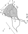
Figs. 3A and3B illustrate an embodiment of thevalve 300 of the present invention.Valve 300 includesframe 302 having an open frame configuration and the first and secondleaflet connection regions leaflet connection regions first vertex 361 and asecond vertex 364, respectively, relative thefirst end 308 of theframe 302. - As illustrated, the
outer surface 312 of theframe 302 can provide a number of frame dimensions. For example, theouter surface 312 of theframe 302 can be viewed as defining afirst frame dimension 366 at thefirst end 308 of theframe 302 and asecond frame dimension 368 between thefirst vertex 361 and thesecond vertex 364 of theframe 302. In one embodiment, thesecond frame dimension 368 can have a larger value as compared to thefirst frame dimension 366. Other dimensional relationships between the first andsecond frame dimensions - In the present invention, the differences in the frame dimensions for
frame 302 allow portions of theframe members 318 to provide the radial support member for thevalve 300. In other words, the radial support member of theframe 302 can result from the relative shape and size of the different portions of theframe members 318. For example, as described herein the first andsecond frame dimensions outer surface 312 of theframe 302 radially arcs from thefirst frame dimension 366 to thesecond frame dimension 368 so as to provide the radial support member of theframe 302. - So, in the present invention, the flaring of the of the
frame member 318 from thefirst frame dimension 366 to thesecond frame dimension 368 allows theframe member 318 in the region of the first andsecond vertex frame members 318 can be pre- and/or post treated to impart the frame dimension differences described herein. For example,frame members 318 forming thefirst vertex 361 and thesecond vertex 364 of theframe 302 could be bent to impart the radial flare. For example, a mandrel having a tapering surface could be used to impart the radial flare to theframe member 318. - The flared first and
second vertex frame 302 could then be heat treated so as to fix the radial flare into theframe member 318. For example, a suitable heat treatment for a nitinol material can include heating theframe member 318 to approximately 500 degrees Celsius for approximately two (2) minutes. Theframe members 318 can then be air cooled or quenched. Other material treatments (plastic deformation, forging, elastic deformation - heat setting) are also possible to impart the radial flare as described herein, many of which are material specific. - In one embodiment, the radial support member illustrated in
Fig. 3 serves to stabilize thevalve 300 once positioned at a predetermined location as described herein. In addition, the configuration of the radial support member can allow thefirst frame dimension 366 and thesecond frame dimension 368 to more closely correspond to each other once thevalve 300 has been positioned at the predetermined location. - The
valve 300 further includes a cover 304, where both theframe 302 and the cover 304 can resiliently radially collapse and expand, as described herein. In the present invention, the cover 304, is located over at least theouter surface 312 of theframe 302 and coupled to the first and secondleaflet connection regions second valve leaflets 346 and 348) and the reversiblysealable opening 316, as described herein. In an embodiment, the cover 304 can also be located over at least theinner surface 314 of theframe 302. A further embodiment includes the cover 304 located over at least theouter surface 312 and theinner surface 314. Anchoring elements (e.g., barbs) and radiopaque markers can also be included withvalve 300, as described herein. - As described herein, the
valve leaflets 322 can include thetransition region 352 where the circumference of the cover 304 changes from a first circumference to a second circumference that is smaller than the first circumference. Thetransition region 352 also allows for thegap 354, as described herein, to be formed between the outer surface of thevalve leaflets 322 and the inner wall of the vessel in which thevalve 300 is implanted. Thevalve leaflets 322 can also include theconcave pocket 360, as described herein. Cover 304 also includes thelip 356 that can have either a non-planar or a planar configuration, as described herein. -
Frame member 318 of thevalve frame 302 can also include a variety of cross-sectional shapes and dimensions. For example, cross-sectional shapes for theframe member 318 can be as described herein. In addition, theframe member 318 can have two or more cross-sectional shapes, two or more different dimensions (e.g., a greater width and depth of theframe member 318 for the first andsecond vertices -
Figs. 4A and4B illustrate additional embodiments of thevalve 400. As illustrated, theframe 402 includes an open frame configuration and the firstleaflet connection region 426 and the secondleaflet connection region 428, as described herein.Figs. 4A and4B illustrate embodiments in which thecover 404 can be positioned at different locations along theframe 402 so as to form the valve leaflets 422. For example, inFig. 4A theleaflet connection regions first vertex 461 and thesecond vertex 464, respectively, relative thefirst end 408 of theframe 402. In an additional example,Fig. 4B provides an illustration in which theleaflet connection regions frame 402 having thefirst vertex 461 and thesecond vertex 464 and thefirst end 408 of theframe 402. - The
frame 402 can include multiple structural configurations. For example, theframe 402 includes asupport frame region 470 that helps to stabilize and position thevalve 400 inside a vessel. In one embodiment,Figs. 4A and4B provide an illustration in which thesupport frame region 470 extends from anaxis 472 through a mid-point of theframe 402 away from theleaflet connection regions - As illustrated, the
outer surface 412 of theframe 402 also provides number of frame dimensions. For example, theouter surface 412 of theframe 402 can be viewed as defining thefirst frame dimension 466 at theaxis 472 of theframe 402 and asecond frame dimension 468 measure at either the first orsecond end frame 402. In one embodiment, thesecond frame dimension 468 can have a larger value as compared to thefirst frame dimension 466. Other dimensional relationships between the first andsecond frame dimensions - In the present embodiment, the differences in the
frame 402 dimensions provide radial support members for thevalve 400. In other words, radial support members of theframe 402 result from the relative shape and size of the different portions of theframe members 418. For example, as described herein the first andsecond frame dimensions outer surface 412 of theframe 402 radially arcs from thefirst frame dimension 466 to thesecond frame dimension 468 so as to provide the radial support member of theframe 402. So, in the present example the flaring of the of theframe member 418 from thefirst frame dimension 466 to thesecond frame dimension 468 allows theframe member 418 in the region of the first andsecond vertex - In this embodiment, the radial support members illustrated in
Figs. 4A and4B serve to stabilize thevalve 400 once positioned at a predetermined location as described herein. In addition, the configuration of the radial support member can allow thefirst frame dimension 466 and thesecond frame dimension 468 to more closely correspond to each other once thevalve 400 has been positioned at the predetermined location. - The
valve 400 further includes acover 404, where both theframe 402 and thecover 404 can resiliently radially collapse and expand, as described herein. In the present invention, thecover 404 is located over at least theinner surface 414 of theframe 402 and coupled to the first and secondleaflet connection regions second valve leaflets 446 and 448) and the reversiblysealable opening 416, as described herein. In an embodiment, thecover 404 can also be located over at least theouter surface 412 of theframe 402. A further embodiment includes thecover 404 located over at least theouter surface 412 and theinner surface 414. Anchoring elements (e.g., barbs) and radiopaque markers can also be included withvalve 400, as described herein. -
Frame member 418 of thevalve frame 402 can also include a variety of cross-sectional shapes and dimensions. For example, cross-sectional shapes for theframe member 418 can be as described herein. In addition, theframe member 418 can have two or more cross-sectional shapes, two or more different dimensions (e.g., a greater width and depth of theframe member 418 for one or more of the first andsecond vertices -
Figs. 5A and5B illustrate an additional example of thevalve 500.Valve 500 includes thecover 504 as described herein. Theframe 502 of thevalve 500 further includes atriple wishbone configuration 574. In one example, thetriple wishbone configuration 574 of theframe 502 includes a series of interconnected bifurcated members having connection points that act as spring members, as will be described herein. In one example, the interconnection of these members allows for the spring force of aligned springs integrated into theframe 502 to be added in series so as to increase the spring force potential of theframe 502. -
Fig. 5B provides an illustration of thetriple wishbone configuration 574 for theframe 502 that has been cut to provide it in a planar view. In one example, theframe member 518 in thetriple wishbone configuration 574 includes aradial support member 534. As illustrated, theradial support member 534 can be in the form of atubular ring 536 that can move radially as thevalve 500 radially collapses and expands. - In one example, the
tubular ring 536 can provide a spring force (e.g., elastic potential energy) to counter radial compression of theframe 502 towards its uncompressed state. For example, thetubular ring 536 has a zig-zag configuration that includescorners 538 that can develop the spring force when theframe 502 is under compressed. As will be appreciated, thecorners 538 can have a number of configurations, including turns defining angles and/or arcs (e.g., having a radius of curvature). - The
frame 502 further includesspring members 576 interconnected with theradial support member 534. As illustrated, thespring members 576 are associated with theradial support member 534 adjacent thecorners 538. For example, thespring members 576 can includeextensions 578 that join theradial support member 534 adjacent thecorners 538 along acommon plane 580. In the present embodiment,extensions 578 join theradial support member 534 adjacent eachcorner 538 along theplane 580. - The
spring members 576 also includecorners 538 that can develop the spring force when theframe 502 is under compressed. As will be appreciated, thecorners 538 can have a number of configurations, including turns defining angles and/or arcs (e.g., having a radius of curvature). In one example, thecorners 538 of thespring members 576 also provide the first and secondleaflet connection regions spring members 576 interconnected with theradial support member 534 helps to stabilize the relative positions of theconnection regions 526 and 528 (e.g., limit relative fluctuations of theconnection regions 526 and 528). - The
frame 502 can further include dimensional relationships, as described herein, which allow theframe 502 to flare radially outward relative thefirst end 508 of the frame. Thevalve 500 can further include thecover 504, where both theframe 502 and thecover 504 can resiliently radially collapse and expand, as described herein. In the present example, thecover 504 can be located over at least theinner surface 514 of theframe 502 and coupled to the first and secondleaflet connection regions second valve leaflets 546 and 548) and the reversiblysealable opening 516, as described herein. - The
valve leaflets 522 can further include thetransition region 552 where the circumference of thecover 504 changes from a first circumference to a second circumference that is smaller than the first circumference. Thetransition region 552 also allows for the gap, as described herein, to be formed between the outer surface of thevalve leaflets 522 and the inner wall of the vessel in which thevalve 500 is implanted. Thevalve leaflets 522 can also include theconcave pocket 560, as described herein. Cover 504 also includes thelip 556 that can have either a non-planar or a planar configuration, as described herein. -
Frame member 518 of thevalve frame 502 can also include a variety of cross-sectional shapes and dimensions. For example, cross-sectional shapes for theframe member 518 can be as described herein. In addition, theframe member 518 can have two or more cross-sectional shapes, two or more different dimensions (e.g., a greater width and depth of theframe member 518 for thecorners 538 as compared to the remainder of the frame member 518). -
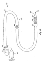
Fig. 6 illustrates asystem 680.System 680 includesvalve 600, as described herein, reversibly joined tocatheter 682. Thecatheter 682 includes anelongate body 684 having aproximal end 686 and adistal end 688, wherevalve 600 can be located between theproximal end 686 anddistal end 688. Thecatheter 682 can further include alumen 690 longitudinally extending to thedistal end 688. In one example,lumen 690 extends betweenproximal end 686 anddistal end 688 ofcatheter 682. Thecatheter 682 can further include aguidewire lumen 692 that extends within theelongate body 684, where theguidewire lumen 692 can receive a guidewire for positioning thecatheter 682 and thevalve 600 within a body lumen (e.g., a vein of a patient). - The
system 680 can further include adeployment shaft 694 positioned withinlumen 690, and asheath 696 positioned adjacent thedistal end 688. In one embodiment, thevalve 600 can be positioned at least partially within thesheath 696 and adjacent thedeployment shaft 694. Thedeployment shaft 694 can be moved within thelumen 690 to deployvalve 600. For example,deployment shaft 694 can be used to pushvalve 600 fromsheath 696 in deployingvalve 600. -
Fig. 7 illustrates an additionalexemplary system 780. Thecatheter 782 includeselongate body 784,lumen 790, aretraction system 798 and a retractable sheath 796. The retractable sheath 796 can be positioned over at least a portion of theelongate body 784, where the retractable sheath 796 can move longitudinally along theelongate body 784. The valve 700 can be positioned at least partially within the retractable sheath 796, where the retractable sheath 796 moves along the elongate body 796 to deploy the valve 700. - In one example,
retraction system 798 includes one ormore wires 701 coupled to the retractable sheath 796, where the wires are positioned at least partially within and extend throughlumen 790 in theelongate body 784. Wires of theretraction system 798 can then be used to retract the retractable sheath 796 in deploying valve 700. In one example, a portion of theelongate body 784 that defines theguidewire lumen 792 extends through thelumen 706 of the valve 700 to protect the valve 700 from the movement of theguidewire 709. -
Fig. 8 illustrates anadditional system 880. Thecatheter 882 includeselongate body 884, aninflatable balloon 803 positioned adjacent thedistal end 888. Theelongate body 884 further includes aninflation lumen 805 longitudinally extending in theelongate body 884 of thecatheter 882 from theinflatable balloon 803 to theproximal end 886. In one example, aninflation pump 807 can be releasably coupled to theinflation lumen 805 and used to inflate and deflate theballoon 803. - In the present example, the
inflatable balloon 803 can be at least partially positioned within thelumen 806 of thevalve 800. Theinflatable balloon 803 can be inflated through thelumen 805 with theinflation pump 807 to deploy thevalve 800. Thesystem 880 can further include theguidewire lumen 892 to receive aguidewire 809. -
Figs. 9A-9C illustrate anadditional system 980. Thesystem 980 includes atubular sheath 911 having anelongate body 913 and alumen 915. Thesystem 980 further includes adelivery shaft 917 positioned within thelumen 915 of thetubular sheath 911. In one example, thetubular sheath 911 and thedelivery shaft 917 can move longitudinally relative each other. -
System 980 also includes aflexible cover 919 between thetubular sheath 911 and thedelivery shaft 917. In one embodiment, theflexible cover 919 is connected to thetubular sheath 911 and thedelivery shaft 917 at a fluidtight seal 921 so as to prevent fluid from outside thesystem 980 entering thelumen 915. As illustrated, the valve 900 can be positioned over thedelivery shaft 915 and theflexible cover 919 adjacent adistal end 923 of thedelivery shaft 917. - In one example, the
tubular sheath 911, thedelivery shaft 917 and theflexible cover 919 can each be formed from a number of different materials. For the tubular sheath examples include, but are not limited to materials selected from one or more of ePTFE, PTFE, PE, PET, silicone, and polyurethanes. For thedelivery shaft 917 examples include, but are not limited to, those selected from a metal, a metal alloy, and/or a polymer. Examples include, but are not limited one or more of ePTFE, PTFE, PE, nylons, PET, silicone, polyurethanes, and stainless steel (e.g., 316L). - In addition, the
delivery shaft 917 can also include a configuration that imparts sufficient column rigidity to allow it to be pushed and/or pulled through thelumen 915. For example, thedelivery shaft 917 can be formed with reinforcing members bound within the body of the delivery shaft 917 (e.g., an elongate braid of stainless steel co-extruded with a polymer). For theflexible cover 919 examples include, but are not limited to, materials selected from one or more of ePTFE, PTFE, PE, PET, nylons, and polyurethanes. As will be appreciated, other materials and configurations for forming thetubular sheath 911, thedelivery shaft 917 and theflexible cover 919 are also possible. - As illustrated in
Figs. 9A-9C , the valve 900 can be held in the samerelative location 925 as it is being deployed. As illustrated inFig. 9A , the valve 900, a portion of theflexible cover 919 and thedelivery shaft 917 can be positioned within thelumen 915 of thetubular sheath 911. In one embodiment, the configuration illustrated inFig. 9A allows the valve 900 to be delivered in its compressed state to a predetermined location in the lumen of the body. Once at the predetermined location, thesheath 911 can then be moved relative thedelivery shaft 917.Fig. 9B illustrates a situation where thesheath 911 has been pulled over the valve 900location 925 and at least partially over thedelivery shaft 917. - As illustrated, the
flexible cover 919 has a tubular configuration that folds back inside of itself (i.e., its lumen) as thetubular sheath 911 is drawn over the valve 900 and thedelivery shaft 917. In one example, thelumen 915 of thesheath 911 can contain a lubricating fluid (e.g., saline) to allow theflexible cover 919 to more easily pass over itself as illustrated. As thetubular sheath 911 continues to be pulled back relative thedelivery shaft 917 until the valve 900 is released, as illustrated inFig. 9C . In one example, the valve 900 can include a self-expanding frame that allows the valve 900 to deploy atlocation 925 once released. - The present invention further includes a method for forming the valve of the present invention, as described herein. The method of forming the valve includes forming the frame having the leaflet connection regions, as described. The method includes providing the radial support member, or members, on the frame for the leaflet connection regions. As described herein, the radial support member includes the the radial flares imparted into the leaflet connection regions. The method also includes providing the cover on the frame, where connecting the cover to the leaflet connection regions provides at least the first leaflet and the second leaflet of the valve having surfaces defining the reversibly sealable opening for unidirectional flow of a liquid through the valve.
- In an additional example, the valve can be reversibly joined to the catheter, which can include a process of altering the shape of the valve from a first shape, for example an expanded state, to the compressed state, as described herein. For example, the valve can be reversibly joined with the catheter by positioning valve in the compressed state at least partially within the sheath of the catheter. In one example, positioning the valve at least partially within the sheath of the catheter includes positioning the valve in the compressed state adjacent the deployment shaft of the catheter. In an another example, the sheath of the catheter functions as a retractable sheath, where the valve in the compressed state can be reversibly joined with the catheter by positioning the valve at least partially within the reversible sheath of the catheter. In a further example, the catheter can include an inflatable balloon, where the balloon can be positioned at least partially within the lumen of the valve, for example, in its compressed state.
- The embodiments of the valve described herein may be used to replace, supplement, or augment valve structures within one or more lumens of the body. For example, embodiments of the present invention may be used to replace an incompetent venous valve and help to decrease backflow of blood in the venous system of the legs.
- In one example, the method of replacing, supplementing, and/or augmenting a valve structure can include positioning at least part of the catheter including the valve at a predetermined location within the lumen of a body. For example, the predetermined location can include a position within a body lumen of a venous system of a patient, such as a vein of a leg.
- In one example, positioning the catheter that includes the valve within the body lumen of a venous system includes introducing the catheter into the venous system of the patient using minimally invasive percutaneous, transluminal catheter based delivery system, as is known in the art. For example, a guidewire can be positioned within a body lumen of a patient that includes the predetermined location. The catheter, including valve, as described herein, can be positioned over the guidewire and the catheter advanced so as to position the valve at or adjacent the predetermined location.
- As described herein, the position of the one or more radiopaque markers can be selected so as to provide information on the position, location and orientation (e.g., axial, directional, and/or clocking position) of the valve during its implantation. For example, radiopaque markers can be configured radially and longitudinally on predetermined portions of the valve frame and/or the elongate body of the catheter to indicate not only a longitudinal position, but also a radial position of the valve leaflets and the valve frame (referred to as a clock position). In one example, the radiopaque markers are configures to provide radiographic images that indicate the relative radial position of the valve and valve leaflets on the catheter.
-
Figs. 10A-10C provide an illustration of theradiopaque markers 1027 associated with theelongate body 1084 of thecatheter 1082. As illustrated, theradiopaque markers 1027 include aradial component 1029 and alongitudinal component 1031. Depending upon the radial position of thecatheter 1082, theradiopaque markers 1027 can provide a different and distinguishable radiographic image. For example, in a first position 1033 illustrated inFig. 10A thelongitudinal component 1031 of theradiopaque markers 1027 are aligned so as to overlap. As thecatheter 1082 is rotated, as illustrated inFigs. 10B and 10C , the radiographic image of theradial component 1029 and/orlongitudinal component 1031 of theradiopaque markers 1027 change. - The change in the relationship of the radial and
longitudinal components catheter 1082 is rotated allows for the relative position of the valve, valve frame and valve leaflets to be determined from the radiographic image. For example, the relative position of the first and secondleaflet connection regions longitudinal component 1031 of theradiopaque markers 1027. This would allow the clock position for thevalve 1000 to be determined so that the valve can be positioned in a more natural orientation relative the compressive forces the valve will experience in situ. In other words, the allowing for clocking of thevalve 1000 as described herein allows the valve to be radially positioned in same orientation as native valve that it's replacing and/or augmenting. - As will be appreciated, other relative relationships between the
radiopaque markers 1027 and the position of thevalve 1000 on thecatheter 1082 are possible. For example, additionalradiopaque markers 1027 on thevalve 1000 could be used either alone or in combination withradiopaque markers 1027 on thecatheter 1082 to help in positioning thevalve 1000 within a lumen. - The valve can be deployed from the catheter at the predetermined location in a number of ways, as described herein. In one example, valve of the present invention can be deployed and placed in a number of vascular locations. For example, valve can be deployed and placed within a major vein of a patient's leg. In one example, major veins include, but are not limited to, those of the peripheral venous system. Examples of veins in the peripheral venous system include, but are not limited to, the superficial veins such as the short saphenous vein and the greater saphenous vein, and the veins of the deep venous system, such as the popliteal vein and the femoral vein.
- As described herein, the valve can be deployed from the catheter in a number of ways. For example, the catheter can include the retractable sheath in which valve can be at least partially housed, as described herein. Valve can be deployed by retracting the retractable sheath of the catheter, where the valve self-expands to be positioned at the predetermined location. In an additional example, the catheter can include a deployment shaft and sheath in which valve can be at least partially housed adjacent the deployment shaft, as described herein. Valve can be deployed by moving the deployment shaft through the catheter to deploy valve from the sheath, where the valve self-expands to be positioned at the predetermined location. In an additional example, the valve can be deployed through the use of an inflatable balloon.
- Once implanted, the valve can provide sufficient contact and expansion force against the body lumen wall to prevent retrograde flow between the valve and the body lumen wall. For example, the valve can be selected to have a larger expansion diameter than the diameter of the inner wall of the body lumen. This can then allow valve to exert a force on the body lumen wall and accommodate changes in the body lumen diameter, while maintaining the proper placement of valve. As described herein, the valve can engage the lumen so as to reduce the volume of retrograde flow through and around valve. It is, however, understood that some leaking or fluid flow may occur between the valve and the body lumen and/or through valve leaflets.
- In addition, the use of both the radial support member and/or the support frame region of the valve can provide a self centering aspect to valve within a body lumen. In one example, the self centering aspect resulting from the radial support member and/or the support frame region may allow valve to maintain a substantially coaxial alignment with the body lumen (e.g., such as a vein) as valve leaflets deflect between the open and closed configurations so as to better seal the reversible opening when valve is closed.
- While the present invention has been shown and described in detail above, it will be clear to the person skilled in the art that changes and modifications may be. As such, that which is set forth in the foregoing description and accompanying drawings is offered by way of illustration only and not as a limitation.
- In addition, one of ordinary skill in the art will appreciate upon reading and understanding this disclosure that other variations for the invention described herein can be included. For example, the
frame 102 and/or thecover 104 can be coated with a non-thrombogenic biocompatible material, as are known or will be known. - In the foregoing Detailed Description, various features are grouped together in several embodiments for the purpose of streamlining the disclosure.
Claims (15)
- A valve (300), comprising:a frame (302) including an outer surface (312) and an inner surface (314) opposite the outer surface (312) and defining a lumen, where the frame (302) further includes frame members (318) to provide a radial support member for the valve (300); anda cover (304), where the cover (304) extends to at least a first leaflet connection region (326) and a second leaflet connection region (328) on the frame (302) adjacent the radial support member to form a first valve leaflet (346) and a second valve leaflet (348), the first valve leaflet (346) and the second valve leaflet (348) having surfaces defining a reversibly sealable opening (316) for unidirectional flow of a liquid through the lumen,wherein the first leaflet connection region (326) and the second leaflet connection region (328) provide a first vertex (361) and a second vertex (364), respectively, relative a first end (308) of the frame,characterized in that the outer surface (312) of the frame (302) defines a first frame dimension (366) at the first end (308) of the frame (302) and a second frame dimension (368) between the first vertex (361) and the second vertex (364) of the frame (302),wherein the frame members (318) flare from the first frame dimension (366) to the second frame dimension (368) to allow the frame members (318) in the region of the first vertex (361) and second vertex (364) to provide the radial support member.
- The valve of claim 1, where the second frame dimension (368) is larger than the first frame dimension (366).
- The valve of claim 2, where the outer surface (312) of the frame radially arcs from the first frame dimension (366) to the second frame dimension (368) so as to provide the radial support member of the frame (302).
- The valve of any of the preceding claims, where the first leaflet connection region (326) and the second leaflet connection region (328) are positioned opposite each other along a common axis.
- The valve of any of the preceding claims, where the cover (304) is over the outer surface (312) of the frame (302).
- The valve of any of the preceding claims, wherein the cover (304) is also located over the inner surface (314) of the frame (302).
- The valve of any of the preceding claims, wherein the cover (304) is located over the outer surface (312) and the inner surface (314).
- The valve of any of the preceding claims, wherein the valve leaflets (322) include a transition region (352) where the circumference of the cover (304) changes from a first circumference to a second circumference that is smaller than the first circumference.
- The valve of any of the preceding claims, wherein the valve leaflets (322) form a gap (354) between the outer surface of the valve leaflets (322) and the inner wall of the vessel in which the valve (300) is implanted.
- The valve of any of the preceding claims, wherein the cover (304) includes a lip (356).
- The valve of any of the preceding claims in combination with a catheter comprising a proximal end and a distal end, wherein the valve is located between the proximal end and the distal end of the catheter.
- A method for forming a valve, comprising:forming a frame (302) having leaflet connection regions (326, 328), the frame (302) including an outer surface (312) and an inner surface (314) opposite the outer surface (312) and defining a lumen, where the frame includes frame members (318) to provide a radial support member on the frame for the leaflet connection regions (326, 328);and providing a cover (304) on the frame (302), the cover (304) connected to the leaflet connection regions (326, 328) to provide at least a first leaflet (346) and a second leaflet (348) of a valve having surfaces defining a reversibly sealable opening for unidirectional flow of a liquid through the valve (300); where the first leaflet connection region (326) and the second leaflet connection region (328) provide a first vertex (361) and a second vertex (364), respectively, relative a first end (308) of the frame (302), the outer surface (312) of the frame (302) defining a first frame dimension (366) at the first end (308) of the frame (302) and a second frame dimension (368) between the first vertex (361) and the second vertex (364) of the frame (302);where forming the frame includes flaring the frame members (318) from the first frame dimension (366) to the second frame dimension (368) to allow the frame member (318) in the region of the first vertex (361) and second vertex (364) to provide the radial support member.
- The method of claim 12where the second frame dimension (368) is larger than the first frame dimension (366).
- The method of claim 13, where flaring the leaflet connection regions (326, 328) includes radially arcing the first frame dimension (366) to the second frame dimension (368) so as to provide the radial support member of the frame.
- The method of any of claims 12 to 14, further comprising reversibly joining the valve (300) and a catheter.
Applications Claiming Priority (3)
| Application Number | Priority Date | Filing Date | Title |
|---|---|---|---|
| US11/150,331 US8012198B2 (en) | 2005-06-10 | 2005-06-10 | Venous valve, system, and method |
| EP06772822.0A EP1895943B1 (en) | 2005-06-10 | 2006-06-09 | Venous valve, system and method |
| PCT/US2006/022666 WO2006135831A1 (en) | 2005-06-10 | 2006-06-09 | Venous valve, system and method |
Related Parent Applications (2)
| Application Number | Title | Priority Date | Filing Date |
|---|---|---|---|
| EP06772822.0A Division-Into EP1895943B1 (en) | 2005-06-10 | 2006-06-09 | Venous valve, system and method |
| EP06772822.0A Division EP1895943B1 (en) | 2005-06-10 | 2006-06-09 | Venous valve, system and method |
Publications (2)
| Publication Number | Publication Date |
|---|---|
| EP2497445A1 EP2497445A1 (en) | 2012-09-12 |
| EP2497445B1 true EP2497445B1 (en) | 2020-08-12 |
Family
ID=37189039
Family Applications (2)
| Application Number | Title | Priority Date | Filing Date |
|---|---|---|---|
| EP06772822.0A Not-in-force EP1895943B1 (en) | 2005-06-10 | 2006-06-09 | Venous valve, system and method |
| EP12170873.9A Active EP2497445B1 (en) | 2005-06-10 | 2006-06-09 | Valve and system |
Family Applications Before (1)
| Application Number | Title | Priority Date | Filing Date |
|---|---|---|---|
| EP06772822.0A Not-in-force EP1895943B1 (en) | 2005-06-10 | 2006-06-09 | Venous valve, system and method |
Country Status (4)
| Country | Link |
|---|---|
| US (4) | US8012198B2 (en) |
| EP (2) | EP1895943B1 (en) |
| CA (1) | CA2611707C (en) |
| WO (1) | WO2006135831A1 (en) |
Families Citing this family (128)
| Publication number | Priority date | Publication date | Assignee | Title |
|---|---|---|---|---|
| WO2004030568A2 (en) * | 2002-10-01 | 2004-04-15 | Ample Medical, Inc. | Device and method for repairing a native heart valve leaflet |
| US8091556B2 (en) | 2001-04-20 | 2012-01-10 | V-Wave Ltd. | Methods and apparatus for reducing localized circulatory system pressure |
| US7658759B2 (en) * | 2003-04-24 | 2010-02-09 | Cook Incorporated | Intralumenally implantable frames |
| CA2554595C (en) | 2004-02-03 | 2016-03-29 | Atria Medical Inc. | Device and method for controlling in-vivo pressure |
| ITTO20040135A1 (en) | 2004-03-03 | 2004-06-03 | Sorin Biomedica Cardio Spa | CARDIAC VALVE PROSTHESIS |
| WO2005117758A1 (en) * | 2004-05-28 | 2005-12-15 | Cook Incorporated | Exchangeable delivery system for expandable prosthetic devices |
| CA2578156A1 (en) * | 2004-08-26 | 2006-03-09 | Cook Incorporated | Delivery system with controlled frictional properties |
| US7566343B2 (en) | 2004-09-02 | 2009-07-28 | Boston Scientific Scimed, Inc. | Cardiac valve, system, and method |
| JP4589395B2 (en) * | 2004-09-10 | 2010-12-01 | クック インコーポレイテッド | Prosthetic valve with holes |
| AU2005294316A1 (en) * | 2004-10-06 | 2006-04-20 | Cook Incorporated | Medical device with bioactive agent |
| US7563276B2 (en) * | 2004-10-29 | 2009-07-21 | Cook Incorporated | Intraluminal medical device with cannula for controlled retrograde flow |
| WO2006060546A2 (en) * | 2004-12-01 | 2006-06-08 | Cook Incorporated | Valve with leak path |
| EP1848368A1 (en) * | 2004-12-20 | 2007-10-31 | Cook Incorporated | Intraluminal support frame and medical devices including the support frame |
| DE102005003632A1 (en) | 2005-01-20 | 2006-08-17 | Fraunhofer-Gesellschaft zur Förderung der angewandten Forschung e.V. | Catheter for the transvascular implantation of heart valve prostheses |
| US20060173490A1 (en) * | 2005-02-01 | 2006-08-03 | Boston Scientific Scimed, Inc. | Filter system and method |
| ITTO20050074A1 (en) | 2005-02-10 | 2006-08-11 | Sorin Biomedica Cardio Srl | CARDIAC VALVE PROSTHESIS |
| US20060212107A1 (en) * | 2005-03-17 | 2006-09-21 | Case Brian C | Delivery systems, kits and methods for implanting an intraluminal medical device in a body vessel |
| ATE454862T1 (en) * | 2005-03-24 | 2010-01-15 | Cook Inc | INTERCHANGEABLE DELIVERY SYSTEM WITH DISTAL PROTECTION |
| WO2006124647A1 (en) * | 2005-05-13 | 2006-11-23 | Cook Incorporated | Medical device delivery systems that facilitate medical device placement in the presence of ultrasonic waves |
| US8043352B2 (en) * | 2005-05-24 | 2011-10-25 | Cook Medical Technologies Llc | Medical device delivery system with captive inner member |
| US8012198B2 (en) | 2005-06-10 | 2011-09-06 | Boston Scientific Scimed, Inc. | Venous valve, system, and method |
| US8702785B2 (en) * | 2005-12-30 | 2014-04-22 | Cordis Corporation | Migration resistant prosthetic stent graft for treatment of abdominal aortic aneurysm |
| WO2007083288A2 (en) | 2006-01-23 | 2007-07-26 | Atria Medical Inc. | Heart anchor device |
| US7780724B2 (en) * | 2006-02-24 | 2010-08-24 | California Institute Of Technology | Monolithic in situ forming valve system |
| US8092517B2 (en) * | 2006-05-25 | 2012-01-10 | Deep Vein Medical, Inc. | Device for regulating blood flow |
| US7811316B2 (en) | 2006-05-25 | 2010-10-12 | Deep Vein Medical, Inc. | Device for regulating blood flow |
| WO2008100382A2 (en) * | 2007-01-30 | 2008-08-21 | California Institute Of Technology | Monolithic in-situ forming valve system |
| US9415567B2 (en) | 2007-02-05 | 2016-08-16 | Boston Scientific Scimed, Inc. | Synthetic composite structures |
| US7896915B2 (en) | 2007-04-13 | 2011-03-01 | Jenavalve Technology, Inc. | Medical device for treating a heart valve insufficiency |
| EP2155114B8 (en) * | 2007-06-04 | 2020-05-20 | St. Jude Medical, LLC | Prosthetic heart valves |
| US9848981B2 (en) | 2007-10-12 | 2017-12-26 | Mayo Foundation For Medical Education And Research | Expandable valve prosthesis with sealing mechanism |
| US20090105813A1 (en) * | 2007-10-17 | 2009-04-23 | Sean Chambers | Implantable valve device |
| US7806921B2 (en) * | 2007-11-08 | 2010-10-05 | Cook Incorporated | Monocusp valve design |
| EP2222247B1 (en) * | 2007-11-19 | 2012-08-22 | Cook Medical Technologies LLC | Valve frame |
| ES2903231T3 (en) | 2008-02-26 | 2022-03-31 | Jenavalve Tech Inc | Stent for positioning and anchoring a valve prosthesis at an implantation site in a patient's heart |
| US9044318B2 (en) | 2008-02-26 | 2015-06-02 | Jenavalve Technology Gmbh | Stent for the positioning and anchoring of a valvular prosthesis |
| US20090248142A1 (en) * | 2008-03-25 | 2009-10-01 | Medtronic Vascular, Inc. | Methods, Devices and Systems for Treating Venous Insufficiency |
| EP2105110B2 (en) * | 2008-03-27 | 2018-03-21 | Genomnia S.r.l. | Valve prosthesis for implantation in body channels |
| EP2119417B2 (en) † | 2008-05-16 | 2020-04-29 | Sorin Group Italia S.r.l. | Atraumatic prosthetic heart valve prosthesis |
| GB0810749D0 (en) | 2008-06-11 | 2008-07-16 | Angiomed Ag | Catherter delivery device |
| US9750625B2 (en) | 2008-06-11 | 2017-09-05 | C.R. Bard, Inc. | Catheter delivery device |
| JP2012504031A (en) | 2008-09-29 | 2012-02-16 | カルディアック バルブ テクノロジーズ,インコーポレーテッド | Heart valve |
| EP2845569A1 (en) | 2008-10-01 | 2015-03-11 | Cardiaq Valve Technologies, Inc. | Delivery system for vascular implant |
| EP2682072A1 (en) | 2008-12-23 | 2014-01-08 | Sorin Group Italia S.r.l. | Expandable prosthetic valve having anchoring appendages |
| US8372140B2 (en) * | 2009-01-07 | 2013-02-12 | Cook Medical Technologies Llc | Implantable valve prosthesis with independent frame elements |
| US8348997B2 (en) * | 2009-02-24 | 2013-01-08 | Medtronic Vascular, Inc. | One-way replacement valve |
| WO2010121076A2 (en) | 2009-04-15 | 2010-10-21 | Cardiaq Valve Technologies, Inc. | Vascular implant and delivery system |
| EP2427143B1 (en) | 2009-05-04 | 2017-08-02 | V-Wave Ltd. | Device for regulating pressure in a heart chamber |
| US20210161637A1 (en) | 2009-05-04 | 2021-06-03 | V-Wave Ltd. | Shunt for redistributing atrial blood volume |
| US9034034B2 (en) | 2010-12-22 | 2015-05-19 | V-Wave Ltd. | Devices for reducing left atrial pressure, and methods of making and using same |
| US10076403B1 (en) | 2009-05-04 | 2018-09-18 | V-Wave Ltd. | Shunt for redistributing atrial blood volume |
| DE102009037739A1 (en) * | 2009-06-29 | 2010-12-30 | Be Innovative Gmbh | Percutaneously implantable valve stent, device for its application and method for producing the valve stent |
| US8579964B2 (en) | 2010-05-05 | 2013-11-12 | Neovasc Inc. | Transcatheter mitral valve prosthesis |
| IT1400327B1 (en) | 2010-05-21 | 2013-05-24 | Sorin Biomedica Cardio Srl | SUPPORT DEVICE FOR VALVULAR PROSTHESIS AND CORRESPONDING CORRESPONDENT. |
| CN103002833B (en) | 2010-05-25 | 2016-05-11 | 耶拿阀门科技公司 | Artificial heart valve and comprise artificial heart valve and support through conduit carry interior prosthese |
| US9326853B2 (en) * | 2010-07-23 | 2016-05-03 | Edwards Lifesciences Corporation | Retaining mechanisms for prosthetic valves |
| US9039759B2 (en) | 2010-08-24 | 2015-05-26 | St. Jude Medical, Cardiology Division, Inc. | Repositioning of prosthetic heart valve and deployment |
| US8814931B2 (en) | 2010-08-24 | 2014-08-26 | St. Jude Medical, Cardiology Division, Inc. | Staged deployment devices and methods for transcatheter heart valve delivery systems |
| EP2613737B2 (en) | 2010-09-10 | 2023-03-15 | Symetis SA | Valve replacement devices, delivery device for a valve replacement device and method of production of a valve replacement device |
| AU2015258284B2 (en) * | 2010-09-10 | 2017-09-28 | Symetis Sa | Valve replacement devices, delivery device for a valve replacement device and method of production of a valve replacement device |
| EP2616007B1 (en) | 2010-09-17 | 2020-06-03 | St. Jude Medical, Cardiology Division, Inc. | Staged deployment devices for transcatheter heart valve delivery |
| EP4176842A1 (en) | 2010-09-20 | 2023-05-10 | St. Jude Medical, Cardiology Division, Inc. | Valve leaflet attachment in collapsible prosthetic valves |
| JP5926265B2 (en) | 2010-09-24 | 2016-05-25 | シメティス・ソシエテ・アノニムSymetis Sa | Stent valve, delivery device, and delivery method |
| US9579197B2 (en) * | 2010-12-15 | 2017-02-28 | Medtronic Vascular, Inc. | Systems and methods for positioning a heart valve using visual markers |
| US8932343B2 (en) * | 2011-02-01 | 2015-01-13 | St. Jude Medical, Cardiology Division, Inc. | Blunt ended stent for prosthetic heart valve |
| US9717593B2 (en) | 2011-02-01 | 2017-08-01 | St. Jude Medical, Cardiology Division, Inc. | Leaflet suturing to commissure points for prosthetic heart valve |
| EP2486893B1 (en) | 2011-02-14 | 2017-07-05 | Sorin Group Italia S.r.l. | Sutureless anchoring device for cardiac valve prostheses |
| EP2486894B1 (en) | 2011-02-14 | 2021-06-09 | Sorin Group Italia S.r.l. | Sutureless anchoring device for cardiac valve prostheses |
| US9308087B2 (en) | 2011-04-28 | 2016-04-12 | Neovasc Tiara Inc. | Sequentially deployed transcatheter mitral valve prosthesis |
| US9554897B2 (en) | 2011-04-28 | 2017-01-31 | Neovasc Tiara Inc. | Methods and apparatus for engaging a valve prosthesis with tissue |
| US9629715B2 (en) | 2011-07-28 | 2017-04-25 | V-Wave Ltd. | Devices for reducing left atrial pressure having biodegradable constriction, and methods of making and using same |
| US11135054B2 (en) | 2011-07-28 | 2021-10-05 | V-Wave Ltd. | Interatrial shunts having biodegradable material, and methods of making and using same |
| US9668859B2 (en) | 2011-08-05 | 2017-06-06 | California Institute Of Technology | Percutaneous heart valve delivery systems |
| US9060860B2 (en) | 2011-08-18 | 2015-06-23 | St. Jude Medical, Cardiology Division, Inc. | Devices and methods for transcatheter heart valve delivery |
| EP3281608B1 (en) | 2012-02-10 | 2020-09-16 | CVDevices, LLC | Medical product comprising a frame and visceral pleura |
| US9345573B2 (en) | 2012-05-30 | 2016-05-24 | Neovasc Tiara Inc. | Methods and apparatus for loading a prosthesis onto a delivery system |
| US10004597B2 (en) * | 2012-07-03 | 2018-06-26 | St. Jude Medical, Cardiology Division, Inc. | Stent and implantable valve incorporating same |
| AU2014214700B2 (en) | 2013-02-11 | 2018-01-18 | Cook Medical Technologies Llc | Expandable support frame and medical device |
| US9367681B1 (en) | 2013-02-23 | 2016-06-14 | Fireeye, Inc. | Framework for efficient security coverage of mobile software applications using symbolic execution to reach regions of interest within an application |
| US10583002B2 (en) | 2013-03-11 | 2020-03-10 | Neovasc Tiara Inc. | Prosthetic valve with anti-pivoting mechanism |
| US9681951B2 (en) | 2013-03-14 | 2017-06-20 | Edwards Lifesciences Cardiaq Llc | Prosthesis with outer skirt and anchors |
| WO2014144247A1 (en) | 2013-03-15 | 2014-09-18 | Arash Kheradvar | Handle mechanism and functionality for repositioning and retrieval of transcatheter heart valves |
| US9572665B2 (en) | 2013-04-04 | 2017-02-21 | Neovasc Tiara Inc. | Methods and apparatus for delivering a prosthetic valve to a beating heart |
| WO2014188279A2 (en) | 2013-05-21 | 2014-11-27 | V-Wave Ltd. | Apparatus and methods for delivering devices for reducing left atrial pressure |
| US9655723B2 (en) | 2013-08-05 | 2017-05-23 | Savant Holdings LLC | One-way heart assist valve |
| WO2015027008A1 (en) * | 2013-08-22 | 2015-02-26 | St. Jude Medical, Cardiology Division, Inc. | Stent with alternative cell shapes |
| JP6563394B2 (en) | 2013-08-30 | 2019-08-21 | イェーナヴァルヴ テクノロジー インコーポレイテッド | Radially foldable frame for an artificial valve and method for manufacturing the frame |
| US9549818B2 (en) | 2013-11-12 | 2017-01-24 | St. Jude Medical, Cardiology Division, Inc. | Pneumatically power-assisted tavi delivery system |
| WO2015123607A2 (en) * | 2014-02-13 | 2015-08-20 | Valvexchange, Inc. | Temporary sub-valvular check valve |
| US20170189175A1 (en) | 2014-05-07 | 2017-07-06 | Baylor College Of Medicine | Artificial, flexible valves and methods of fabricating and serially expanding the same |
| EP2954875B1 (en) | 2014-06-10 | 2017-11-15 | St. Jude Medical, Cardiology Division, Inc. | Stent cell bridge for cuff attachment |
| WO2016177562A1 (en) | 2015-05-01 | 2016-11-10 | Jenavalve Technology, Inc. | Device and method with reduced pacemaker rate in heart valve replacement |
| EP3291773A4 (en) | 2015-05-07 | 2019-05-01 | The Medical Research, Infrastructure, And Health Services Fund Of The Tel Aviv Medical Center | Temporary interatrial shunts |
| KR20180067537A (en) | 2015-10-13 | 2018-06-20 | 베나룸 메디컬, 엘엘씨 | Implantable Valves and Methods |
| US10143554B2 (en) | 2015-12-03 | 2018-12-04 | Medtronic Vascular, Inc. | Venous valve prostheses |
| WO2017127939A1 (en) | 2016-01-29 | 2017-08-03 | Neovasc Tiara Inc. | Prosthetic valve for avoiding obstruction of outflow |
| WO2017195125A1 (en) | 2016-05-13 | 2017-11-16 | Jenavalve Technology, Inc. | Heart valve prosthesis delivery system and method for delivery of heart valve prosthesis with introducer sheath and loading system |
| US10835394B2 (en) | 2016-05-31 | 2020-11-17 | V-Wave, Ltd. | Systems and methods for making encapsulated hourglass shaped stents |
| US20170340460A1 (en) | 2016-05-31 | 2017-11-30 | V-Wave Ltd. | Systems and methods for making encapsulated hourglass shaped stents |
| US10098740B2 (en) * | 2016-07-15 | 2018-10-16 | Covidien Lp | Venous valve prostheses |
| US10959841B2 (en) | 2016-11-15 | 2021-03-30 | Hancock Jaffe Laboratories, Inc. | Implantable vein frame |
| CN113893064A (en) | 2016-11-21 | 2022-01-07 | 内奥瓦斯克迪亚拉公司 | Methods and systems for rapid retrieval of transcatheter heart valve delivery systems |
| EP3547964A1 (en) | 2016-12-02 | 2019-10-09 | St. Jude Medical, Cardiology Division, Inc. | Transcatheter delivery system with transverse wheel actuation |
| EP3547965A1 (en) | 2016-12-02 | 2019-10-09 | St. Jude Medical, Cardiology Division, Inc. | Transcatheter delivery system with two modes of actuation |
| US11197754B2 (en) | 2017-01-27 | 2021-12-14 | Jenavalve Technology, Inc. | Heart valve mimicry |
| US11291807B2 (en) | 2017-03-03 | 2022-04-05 | V-Wave Ltd. | Asymmetric shunt for redistributing atrial blood volume |
| CA3054891A1 (en) | 2017-03-03 | 2018-09-07 | V-Wave Ltd. | Shunt for redistributing atrial blood volume |
| WO2018213091A1 (en) | 2017-05-15 | 2018-11-22 | St. Jude Medical, Cardiology Division, Inc. | Transcatheter delivery system with wheel actuation |
| EP3672530A4 (en) | 2017-08-25 | 2021-04-14 | Neovasc Tiara Inc. | Sequentially deployed transcatheter mitral valve prosthesis |
| WO2019142152A1 (en) | 2018-01-20 | 2019-07-25 | V-Wave Ltd. | Devices and methods for providing passage between heart chambers |
| US10898698B1 (en) | 2020-05-04 | 2021-01-26 | V-Wave Ltd. | Devices with dimensions that can be reduced and increased in vivo, and methods of making and using the same |
| US11458287B2 (en) | 2018-01-20 | 2022-10-04 | V-Wave Ltd. | Devices with dimensions that can be reduced and increased in vivo, and methods of making and using the same |
| CN117481869A (en) | 2018-01-25 | 2024-02-02 | 爱德华兹生命科学公司 | Delivery system for assisting in recapture and repositioning of replacement valves after deployment |
| CN110353858A (en) * | 2018-04-09 | 2019-10-22 | 倍芮医疗器械(上海)有限公司 | For loading the bracket and venous valve displacement apparatus of valve |
| CN112437649A (en) | 2018-05-23 | 2021-03-02 | 索林集团意大利有限责任公司 | Heart valve prosthesis |
| US11737872B2 (en) | 2018-11-08 | 2023-08-29 | Neovasc Tiara Inc. | Ventricular deployment of a transcatheter mitral valve prosthesis |
| WO2020142336A1 (en) | 2019-01-03 | 2020-07-09 | Renovo Medsolutions, Llc | Venous valve prosthesis |
| JP7438236B2 (en) | 2019-04-01 | 2024-02-26 | ニオバスク ティアラ インコーポレイテッド | Controllably deployable prosthetic valve |
| US11612385B2 (en) | 2019-04-03 | 2023-03-28 | V-Wave Ltd. | Systems and methods for delivering implantable devices across an atrial septum |
| EP3952792A4 (en) * | 2019-04-10 | 2023-01-04 | Neovasc Tiara Inc. | Prosthetic valve with natural blood flow |
| US11779742B2 (en) | 2019-05-20 | 2023-10-10 | Neovasc Tiara Inc. | Introducer with hemostasis mechanism |
| EP3972499A1 (en) | 2019-05-20 | 2022-03-30 | V-Wave Ltd. | Systems and methods for creating an interatrial shunt |
| AU2020295566B2 (en) | 2019-06-20 | 2023-07-20 | Neovasc Tiara Inc. | Low profile prosthetic mitral valve |
| WO2022046921A1 (en) | 2020-08-25 | 2022-03-03 | Shifamed Holdings, Llc | Adjustable interatrial shunts and associated systems and methods |
| EP4243915A1 (en) | 2020-11-12 | 2023-09-20 | Shifamed Holdings, LLC | Adjustable implantable devices and associated methods |
| US11234702B1 (en) | 2020-11-13 | 2022-02-01 | V-Wave Ltd. | Interatrial shunt having physiologic sensor |
| WO2023199267A1 (en) | 2022-04-14 | 2023-10-19 | V-Wave Ltd. | Interatrial shunt with expanded neck region |
| WO2023220254A1 (en) | 2022-05-11 | 2023-11-16 | Envveno Medical Corporation | Transcatheter valve for venous insufficiency |
Citations (3)
| Publication number | Priority date | Publication date | Assignee | Title |
|---|---|---|---|---|
| WO2003094796A1 (en) * | 2002-05-10 | 2003-11-20 | Cordis Corporation | Method of placing a tubular membrane on a structural frame |
| WO2005011535A2 (en) * | 2003-07-31 | 2005-02-10 | Cook Incorporated | Prosthetic valve for implantation in a body vessel |
| WO2005046528A1 (en) * | 2003-10-06 | 2005-05-26 | 3F Therapeutics, Inc. | Minimally invasive valve replacement system |
Family Cites Families (535)
| Publication number | Priority date | Publication date | Assignee | Title |
|---|---|---|---|---|
| US3671979A (en) | 1969-09-23 | 1972-06-27 | Univ Utah | Catheter mounted artificial heart valve for implanting in close proximity to a defective natural heart valve |
| US4291420A (en) | 1973-11-09 | 1981-09-29 | Medac Gesellschaft Fur Klinische Spezialpraparate Mbh | Artificial heart valve |
| US7018407B1 (en) | 1981-10-29 | 2006-03-28 | Medtronic | Valve holder for tricuspid heart valve |
| US5275622A (en) | 1983-12-09 | 1994-01-04 | Harrison Medical Technologies, Inc. | Endovascular grafting apparatus, system and method and devices for use therewith |
| DE3426300A1 (en) | 1984-07-17 | 1986-01-30 | Doguhan Dr.med. 6000 Frankfurt Baykut | TWO-WAY VALVE AND ITS USE AS A HEART VALVE PROSTHESIS |
| US4935030A (en) | 1985-06-17 | 1990-06-19 | Medtronic, Inc. | Mechanical heart valve prosthesis |
| WO1988000459A1 (en) | 1986-07-17 | 1988-01-28 | Quotidian No. 100 Pty. Limited | Prosthetic venous valve |
| US4872874A (en) | 1987-05-29 | 1989-10-10 | Taheri Syde A | Method and apparatus for transarterial aortic graft insertion and implantation |
| JPS6483251A (en) | 1987-09-24 | 1989-03-29 | Terumo Corp | Instrument for securing inner diameter of cavity of tubular organ |
| IT1218947B (en) | 1988-01-12 | 1990-04-24 | Sorin Biomedica Spa | CARDIAC VALVE PROSTHESIS |
| SE8800244D0 (en) | 1988-01-27 | 1988-01-27 | Medical Innovation Ab | DEVICE FOR CUTTING OF LEFT FLAVORS |
| US4994077A (en) | 1989-04-21 | 1991-02-19 | Dobben Richard L | Artificial heart valve for implantation in a blood vessel |
| WO1990014804A1 (en) | 1989-05-31 | 1990-12-13 | Baxter International Inc. | Biological valvular prosthesis |
| US5609626A (en) | 1989-05-31 | 1997-03-11 | Baxter International Inc. | Stent devices and support/restrictor assemblies for use in conjunction with prosthetic vascular grafts |
| CA2033195C (en) | 1989-06-19 | 1994-11-15 | Hugh H. Trout, Iii | Aortic graft and method for repairing aneurysm |
| US5290300A (en) | 1989-07-31 | 1994-03-01 | Baxter International Inc. | Flexible suture guide and holder |
| US5411552A (en) | 1990-05-18 | 1995-05-02 | Andersen; Henning R. | Valve prothesis for implantation in the body and a catheter for implanting such valve prothesis |
| US5578071A (en) | 1990-06-11 | 1996-11-26 | Parodi; Juan C. | Aortic graft |
| AR246020A1 (en) | 1990-10-03 | 1994-03-30 | Hector Daniel Barone Juan Carl | A ball device for implanting an intraluminous aortic prosthesis, for repairing aneurysms. |
| US5272909A (en) | 1991-04-25 | 1993-12-28 | Baxter International Inc. | Method and device for testing venous valves |
| IT1245750B (en) | 1991-05-24 | 1994-10-14 | Sorin Biomedica Emodialisi S R | CARDIAC VALVE PROSTHESIS, PARTICULARLY FOR REPLACING THE AORTIC VALVE |
| US5370685A (en) | 1991-07-16 | 1994-12-06 | Stanford Surgical Technologies, Inc. | Endovascular aortic valve replacement |
| US5163953A (en) | 1992-02-10 | 1992-11-17 | Vince Dennis J | Toroidal artificial heart valve stent |
| US5258023A (en) | 1992-02-12 | 1993-11-02 | Reger Medical Development, Inc. | Prosthetic heart valve |
| US5234448A (en) | 1992-02-28 | 1993-08-10 | Shadyside Hospital | Method and apparatus for connecting and closing severed blood vessels |
| US5332402A (en) | 1992-05-12 | 1994-07-26 | Teitelbaum George P | Percutaneously-inserted cardiac valve |
| US5982645A (en) | 1992-08-25 | 1999-11-09 | Square D Company | Power conversion and distribution system |
| US5972030A (en) | 1993-02-22 | 1999-10-26 | Heartport, Inc. | Less-invasive devices and methods for treatment of cardiac valves |
| US6010531A (en) | 1993-02-22 | 2000-01-04 | Heartport, Inc. | Less-invasive devices and methods for cardiac valve surgery |
| US5480423A (en) | 1993-05-20 | 1996-01-02 | Boston Scientific Corporation | Prosthesis delivery |
| US5713950A (en) | 1993-11-01 | 1998-02-03 | Cox; James L. | Method of replacing heart valves using flexible tubes |
| FR2718951B1 (en) | 1994-04-26 | 1996-07-26 | Perouse Implant Laboratoire | Tubular stent. |
| US5554185A (en) | 1994-07-18 | 1996-09-10 | Block; Peter C. | Inflatable prosthetic cardiovascular valve for percutaneous transluminal implantation of same |
| EP0804255B1 (en) | 1994-07-29 | 2001-10-04 | Edwards Lifesciences Corporation | Methods for treating implantable biological tissues to mitigate the calcification thereof |
| FR2728457B1 (en) | 1994-12-21 | 1997-03-21 | Franceschi Claude | ARTIFICIAL VALVE FOR BLOOD VESSEL |
| BE1009278A3 (en) * | 1995-04-12 | 1997-01-07 | Corvita Europ | Guardian self-expandable medical device introduced in cavite body, and medical device with a stake as. |
| CA2223160C (en) | 1995-06-07 | 2007-09-18 | St. Jude Medical, Inc. | Prosthetic heart valve with increased lumen |
| US5716370A (en) | 1996-02-23 | 1998-02-10 | Williamson, Iv; Warren | Means for replacing a heart valve in a minimally invasive manner |
| US6402780B2 (en) | 1996-02-23 | 2002-06-11 | Cardiovascular Technologies, L.L.C. | Means and method of replacing a heart valve in a minimally invasive manner |
| US5928916A (en) | 1996-04-25 | 1999-07-27 | Medtronic, Inc. | Ionic attachment of biomolecules with a guanidino moiety to medical device surfaces |
| WO1997048350A1 (en) | 1996-06-20 | 1997-12-24 | Sulzer Vascutek Ltd. | Prosthetic repair of body passages |
| US5741326A (en) | 1996-07-15 | 1998-04-21 | Cordis Corporation | Low profile thermally set wrapped cover for a percutaneously deployed stent |
| JP2002501610A (en) | 1996-07-19 | 2002-01-15 | リージェンツ・オブ・ザ・ユニバーシティ・オブ・ミネソタ | Recombinant SEF14 fimbriae protein from Salmonella |
| US6764509B2 (en) | 1996-09-06 | 2004-07-20 | Carbomedics Inc. | Prosthetic heart valve with surface modification |
| US5895419A (en) | 1996-09-30 | 1999-04-20 | St. Jude Medical, Inc. | Coated prosthetic cardiac device |
| NL1004827C2 (en) | 1996-12-18 | 1998-06-19 | Surgical Innovations Vof | Device for regulating blood circulation. |
| US5879320A (en) | 1996-12-23 | 1999-03-09 | Cazenave; Craig Richard | Implantable vascular device |
| EP0850607A1 (en) | 1996-12-31 | 1998-07-01 | Cordis Corporation | Valve prosthesis for implantation in body channels |
| US5735859A (en) | 1997-02-14 | 1998-04-07 | Cathco, Inc. | Distally attachable and releasable sheath for a stent delivery system |
| DE69828798T2 (en) | 1997-03-05 | 2006-01-05 | Boston Scientific Ltd., St. Michael | CONFORMING, MULTILAYER STENT DEVICE |
| US5928281A (en) | 1997-03-27 | 1999-07-27 | Baxter International Inc. | Tissue heart valves |
| US5961549A (en) | 1997-04-03 | 1999-10-05 | Baxter International Inc. | Multi-leaflet bioprosthetic heart valve |
| JP2001527440A (en) | 1997-04-11 | 2001-12-25 | トランスバスキュラー インコーポレイテッド | Method and device for myocardial penetrating direct coronary remodeling |
| AU8265598A (en) | 1997-06-27 | 1999-01-19 | Trustees Of Columbia University In The City Of New York, The | Method and apparatus for circulatory valve repair |
| DE19731834A1 (en) | 1997-07-24 | 1999-06-17 | Ernst Peter Prof Dr M Strecker | Implantation device |
| FR2768324B1 (en) | 1997-09-12 | 1999-12-10 | Jacques Seguin | SURGICAL INSTRUMENT FOR PERCUTANEOUSLY FIXING TWO AREAS OF SOFT TISSUE, NORMALLY MUTUALLY REMOTE, TO ONE ANOTHER |
| US5910170A (en) | 1997-12-17 | 1999-06-08 | St. Jude Medical, Inc. | Prosthetic heart valve stent utilizing mounting clips |
| EP1049425B1 (en) | 1997-12-29 | 2009-11-25 | Cleveland Clinic Foundation The | System for minimally invasive insertion of a bioprosthetic heart valve |
| US6530952B2 (en) | 1997-12-29 | 2003-03-11 | The Cleveland Clinic Foundation | Bioprosthetic cardiovascular valve system |
| US6074418A (en) | 1998-04-20 | 2000-06-13 | St. Jude Medical, Inc. | Driver tool for heart valve prosthesis fasteners |
| US6200336B1 (en) | 1998-06-02 | 2001-03-13 | Cook Incorporated | Multiple-sided intraluminal medical device |
| US7452371B2 (en) | 1999-06-02 | 2008-11-18 | Cook Incorporated | Implantable vascular device |
| US6250308B1 (en) | 1998-06-16 | 2001-06-26 | Cardiac Concepts, Inc. | Mitral valve annuloplasty ring and method of implanting |
| US6165183A (en) | 1998-07-15 | 2000-12-26 | St. Jude Medical, Inc. | Mitral and tricuspid valve repair |
| US6641610B2 (en) | 1998-09-10 | 2003-11-04 | Percardia, Inc. | Valve designs for left ventricular conduits |
| US6254564B1 (en) | 1998-09-10 | 2001-07-03 | Percardia, Inc. | Left ventricular conduit with blood vessel graft |
| US6921811B2 (en) | 1998-09-22 | 2005-07-26 | Biosurface Engineering Technologies, Inc. | Bioactive coating composition and methods |
| US6355030B1 (en) | 1998-09-25 | 2002-03-12 | Cardiothoracic Systems, Inc. | Instruments and methods employing thermal energy for the repair and replacement of cardiac valves |
| US6051014A (en) | 1998-10-13 | 2000-04-18 | Embol-X, Inc. | Percutaneous filtration catheter for valve repair surgery and methods of use |
| US6540780B1 (en) | 1998-11-23 | 2003-04-01 | Medtronic, Inc. | Porous synthetic vascular grafts with oriented ingrowth channels |
| CA2351671A1 (en) | 1998-11-24 | 2000-06-08 | Regents Of The University Of Minnesota | Transgenic circulating endothelial cells |
| US20040267349A1 (en) | 2003-06-27 | 2004-12-30 | Kobi Richter | Amorphous metal alloy medical devices |
| US6736845B2 (en) | 1999-01-26 | 2004-05-18 | Edwards Lifesciences Corporation | Holder for flexible heart valve |
| EP1146835B1 (en) | 1999-01-26 | 2008-11-19 | Edwards Lifesciences Corporation | Anatomical orifice sizers |
| US6896690B1 (en) | 2000-01-27 | 2005-05-24 | Viacor, Inc. | Cardiac valve procedure methods and devices |
| US6364905B1 (en) | 1999-01-27 | 2002-04-02 | Sulzer Carbomedics Inc. | Tri-composite, full root, stentless valve |
| DE19904975A1 (en) | 1999-02-06 | 2000-09-14 | Impella Cardiotech Ag | Device for intravascular heart valve surgery |
| US6425916B1 (en) | 1999-02-10 | 2002-07-30 | Michi E. Garrison | Methods and devices for implanting cardiac valves |
| US6666886B1 (en) | 1999-02-16 | 2003-12-23 | Regents Of The University Of Minnesota | Tissue equivalent approach to a tissue-engineered cardiovascular valve |
| US6110201A (en) | 1999-02-18 | 2000-08-29 | Venpro | Bifurcated biological pulmonary valved conduit |
| US6139575A (en) | 1999-04-02 | 2000-10-31 | Medtronic, Inc. | Hybrid mechanical heart valve prosthesis |
| US6752813B2 (en) | 1999-04-09 | 2004-06-22 | Evalve, Inc. | Methods and devices for capturing and fixing leaflets in valve repair |
| ATE484241T1 (en) | 1999-04-09 | 2010-10-15 | Evalve Inc | METHOD AND DEVICE FOR HEART VALVE REPAIR |
| US20040044350A1 (en) | 1999-04-09 | 2004-03-04 | Evalve, Inc. | Steerable access sheath and methods of use |
| US7226467B2 (en) | 1999-04-09 | 2007-06-05 | Evalve, Inc. | Fixation device delivery catheter, systems and methods of use |
| US6666885B2 (en) | 1999-04-16 | 2003-12-23 | Carbomedics Inc. | Heart valve leaflet |
| EP1584307A3 (en) | 1999-04-23 | 2005-10-19 | St.Jude Medical ATG, Inc. | Artificial heart valve with attachment fingers |
| BR0010096A (en) | 1999-04-28 | 2002-02-19 | St Jude Medical | Cardiac valve prosthesis, kit, process to connect a cardiac valve prosthesis to a patient, and a fastener applicator to implant a cardiac valve prosthesis |
| AU4673700A (en) | 1999-05-06 | 2000-11-21 | Venpro Corporation | Implant for restoring venous valvular function |
| US6309417B1 (en) | 1999-05-12 | 2001-10-30 | Paul A. Spence | Heart valve and apparatus for replacement thereof |
| US6790229B1 (en) | 1999-05-25 | 2004-09-14 | Eric Berreklouw | Fixing device, in particular for fixing to vascular wall tissue |
| US7628803B2 (en) | 2001-02-05 | 2009-12-08 | Cook Incorporated | Implantable vascular device |
| US6241763B1 (en) | 1999-06-08 | 2001-06-05 | William J. Drasler | In situ venous valve device and method of formation |
| SE514718C2 (en) | 1999-06-29 | 2001-04-09 | Jan Otto Solem | Apparatus for treating defective closure of the mitral valve apparatus |
| US6997951B2 (en) | 1999-06-30 | 2006-02-14 | Edwards Lifesciences Ag | Method and device for treatment of mitral insufficiency |
| US7192442B2 (en) | 1999-06-30 | 2007-03-20 | Edwards Lifesciences Ag | Method and device for treatment of mitral insufficiency |
| US20030055492A1 (en) | 1999-08-20 | 2003-03-20 | Shaolian Samuel M. | Transluminally implantable venous valve |
| KR20020022111A (en) | 1999-08-27 | 2002-03-23 | 로날드 디. 맥크레이 | Absorbent Article Having Pleated Extensible Absorbent Layer |
| US6315793B1 (en) | 1999-09-08 | 2001-11-13 | Medical Carbon Research Institute, Llc | Prosthetic venous valves |
| DE19945587A1 (en) | 1999-09-23 | 2001-05-10 | Co Don Ag | Procedure for inserting implants into human organs |
| US6312447B1 (en) | 1999-10-13 | 2001-11-06 | The General Hospital Corporation | Devices and methods for percutaneous mitral valve repair |
| US6626930B1 (en) | 1999-10-21 | 2003-09-30 | Edwards Lifesciences Corporation | Minimally invasive mitral valve repair method and apparatus |
| US6440164B1 (en) | 1999-10-21 | 2002-08-27 | Scimed Life Systems, Inc. | Implantable prosthetic valve |
| JP2001120582A (en) | 1999-10-22 | 2001-05-08 | Gunze Ltd | Artificial cardiac valve and method of manufacturing the same |
| US6926730B1 (en) | 2000-10-10 | 2005-08-09 | Medtronic, Inc. | Minimally invasive valve repair procedure and apparatus |
| WO2001034068A1 (en) | 1999-11-10 | 2001-05-17 | Impsa International Incorporated | Prosthetic heart valve |
| US7018406B2 (en) | 1999-11-17 | 2006-03-28 | Corevalve Sa | Prosthetic valve for transluminal delivery |
| FR2800984B1 (en) | 1999-11-17 | 2001-12-14 | Jacques Seguin | DEVICE FOR REPLACING A HEART VALVE PERCUTANEOUSLY |
| US8579966B2 (en) | 1999-11-17 | 2013-11-12 | Medtronic Corevalve Llc | Prosthetic valve for transluminal delivery |
| US6458153B1 (en) | 1999-12-31 | 2002-10-01 | Abps Venture One, Ltd. | Endoluminal cardiac and venous valve prostheses and methods of manufacture and delivery thereof |
| US6709457B1 (en) | 1999-11-24 | 2004-03-23 | St. Jude Medical, Inc. | Attachment of suture cuff to prosthetic heart valve |
| SE514886C2 (en) | 1999-12-14 | 2001-05-14 | Jcl Technic Ab | Vascular valve, such as heart valve, and process for its manufacture |
| MXPA02006359A (en) | 1999-12-24 | 2002-11-29 | Toray Industries | Catheter with balloon. |
| WO2001050985A1 (en) | 2000-01-14 | 2001-07-19 | Viacor Incorporated | Tissue annuloplasty band and apparatus and method for fashioning, sizing and implanting the same |
| EP1250165B1 (en) | 2000-01-25 | 2009-05-13 | Edwards Lifesciences Corporation | Bioactive coatings to prevent tissue overgrowth on artificial heart valves |
| EP1264001A1 (en) | 2000-01-25 | 2002-12-11 | Boston Scientific Limited | Manufacturing medical devices by vapor deposition |
| DE60134625D1 (en) | 2000-01-27 | 2008-08-14 | 3F Therapeutics Inc | HEART VALVE PROSTHESIS |
| US7749245B2 (en) | 2000-01-27 | 2010-07-06 | Medtronic, Inc. | Cardiac valve procedure methods and devices |
| US6929653B2 (en) | 2000-12-15 | 2005-08-16 | Medtronic, Inc. | Apparatus and method for replacing aortic valve |
| US6872226B2 (en) | 2001-01-29 | 2005-03-29 | 3F Therapeutics, Inc. | Method of cutting material for use in implantable medical device |
| US6402781B1 (en) | 2000-01-31 | 2002-06-11 | Mitralife | Percutaneous mitral annuloplasty and cardiac reinforcement |
| US7507252B2 (en) | 2000-01-31 | 2009-03-24 | Edwards Lifesciences Ag | Adjustable transluminal annuloplasty system |
| US6989028B2 (en) | 2000-01-31 | 2006-01-24 | Edwards Lifesciences Ag | Medical system and method for remodeling an extravascular tissue structure |
| US6797002B2 (en) | 2000-02-02 | 2004-09-28 | Paul A. Spence | Heart valve repair apparatus and methods |
| US6821297B2 (en) | 2000-02-02 | 2004-11-23 | Robert V. Snyders | Artificial heart valve, implantation instrument and method therefor |
| US20050070999A1 (en) | 2000-02-02 | 2005-03-31 | Spence Paul A. | Heart valve repair apparatus and methods |
| US20030229393A1 (en) | 2001-03-15 | 2003-12-11 | Kutryk Michael J. B. | Medical device with coating that promotes cell adherence and differentiation |
| US6454799B1 (en) | 2000-04-06 | 2002-09-24 | Edwards Lifesciences Corporation | Minimally-invasive heart valves and methods of use |
| US6652583B2 (en) | 2000-04-07 | 2003-11-25 | Rhode Island Hospital | Cardiac valve replacement |
| DE50115407D1 (en) | 2000-04-27 | 2010-05-06 | Corlife Gbr | INDIVIDUAL VEIN CAPTURE PROSTHESIS |
| US7083628B2 (en) | 2002-09-03 | 2006-08-01 | Edwards Lifesciences Corporation | Single catheter mitral valve repair device and method for use |
| US6869444B2 (en) | 2000-05-22 | 2005-03-22 | Shlomo Gabbay | Low invasive implantable cardiac prosthesis and method for helping improve operation of a heart valve |
| US8366769B2 (en) | 2000-06-01 | 2013-02-05 | Edwards Lifesciences Corporation | Low-profile, pivotable heart valve sewing ring |
| US6805711B2 (en) | 2000-06-02 | 2004-10-19 | 3F Therapeutics, Inc. | Expandable medical implant and percutaneous delivery |
| US20050043757A1 (en) | 2000-06-12 | 2005-02-24 | Michael Arad | Medical devices formed from shape memory alloys displaying a stress-retained martensitic state and method for use thereof |
| US6840246B2 (en) | 2000-06-20 | 2005-01-11 | University Of Maryland, Baltimore | Apparatuses and methods for performing minimally invasive diagnostic and surgical procedures inside of a beating heart |
| WO2001097897A1 (en) | 2000-06-20 | 2001-12-27 | Starion Instruments, Inc. | Devices and methods for repair of valves in the human body |
| DE60132005T2 (en) | 2000-06-23 | 2008-12-04 | Viacor Inc., Wilmington | AUTOMATIC WRINKLE FOLDING FOR MITRAL LAPPEN REPAIR |
| US6676698B2 (en) | 2000-06-26 | 2004-01-13 | Rex Medicol, L.P. | Vascular device with valve for approximating vessel wall |
| US6695878B2 (en) | 2000-06-26 | 2004-02-24 | Rex Medical, L.P. | Vascular device for valve leaflet apposition |
| EP1401358B1 (en) | 2000-06-30 | 2016-08-17 | Medtronic, Inc. | Apparatus for performing a procedure on a cardiac valve |
| SE0002514D0 (en) | 2000-06-30 | 2000-06-30 | Pacesetter Ab | Medical device |
| US7077861B2 (en) | 2000-07-06 | 2006-07-18 | Medtentia Ab | Annuloplasty instrument |
| US6419696B1 (en) | 2000-07-06 | 2002-07-16 | Paul A. Spence | Annuloplasty devices and related heart valve repair methods |
| US6695817B1 (en) | 2000-07-11 | 2004-02-24 | Icu Medical, Inc. | Medical valve with positive flow characteristics |
| SE0002878D0 (en) | 2000-08-11 | 2000-08-11 | Kimblad Ola | Device and method of treatment of atrioventricular regurgitation |
| US6635085B1 (en) | 2000-08-17 | 2003-10-21 | Carbomedics Inc. | Heart valve stent with alignment posts |
| US6572652B2 (en) | 2000-08-29 | 2003-06-03 | Venpro Corporation | Method and devices for decreasing elevated pulmonary venous pressure |
| WO2002019951A1 (en) | 2000-09-07 | 2002-03-14 | Viacor, Inc. | Fixation band for affixing a prosthetic heart valve to tissue |
| WO2002022054A1 (en) * | 2000-09-12 | 2002-03-21 | Gabbay S | Valvular prosthesis and method of using same |
| US20060142848A1 (en) | 2000-09-12 | 2006-06-29 | Shlomo Gabbay | Extra-anatomic aortic valve placement |
| DE10046550A1 (en) | 2000-09-19 | 2002-03-28 | Adiam Life Science Ag | Prosthetic mitral heart valve consists of support housing with base ring and two stanchions |
| US8784482B2 (en) | 2000-09-20 | 2014-07-22 | Mvrx, Inc. | Method of reshaping a heart valve annulus using an intravascular device |
| US6893459B1 (en) | 2000-09-20 | 2005-05-17 | Ample Medical, Inc. | Heart valve annulus device and method of using same |
| US8956407B2 (en) | 2000-09-20 | 2015-02-17 | Mvrx, Inc. | Methods for reshaping a heart valve annulus using a tensioning implant |
| WO2004030568A2 (en) | 2002-10-01 | 2004-04-15 | Ample Medical, Inc. | Device and method for repairing a native heart valve leaflet |
| US20050228422A1 (en) | 2002-11-26 | 2005-10-13 | Ample Medical, Inc. | Devices, systems, and methods for reshaping a heart valve annulus, including the use of magnetic tools |
| US20060106279A1 (en) | 2004-05-14 | 2006-05-18 | Ample Medical, Inc. | Devices, systems, and methods for reshaping a heart valve annulus, including the use of a bridge implant having an adjustable bridge stop |
| US20060106278A1 (en) | 2004-05-14 | 2006-05-18 | Ample Medical, Inc. | Devices, systems, and methods for reshaping a heart valve annulus, including the use of an adjustable bridge implant system |
| US7527646B2 (en) | 2000-09-20 | 2009-05-05 | Ample Medical, Inc. | Devices, systems, and methods for retaining a native heart valve leaflet |
| US6461382B1 (en) | 2000-09-22 | 2002-10-08 | Edwards Lifesciences Corporation | Flexible heart valve having moveable commissures |
| AU2001296442A1 (en) | 2000-09-29 | 2002-04-08 | Tricardia, L.L.C. | Venous valvuloplasty device |
| US6602288B1 (en) | 2000-10-05 | 2003-08-05 | Edwards Lifesciences Corporation | Minimally-invasive annuloplasty repair segment delivery template, system and method of use |
| US6723038B1 (en) | 2000-10-06 | 2004-04-20 | Myocor, Inc. | Methods and devices for improving mitral valve function |
| DE10049865B8 (en) | 2000-10-09 | 2008-10-30 | Universitätsklinikum Freiburg | Device for removing an aortic valve on the human heart by means of a minimally invasive surgical procedure |
| DE10050092A1 (en) | 2000-10-09 | 2002-04-11 | Adiam Life Science Ag | Prosthetic mitral valve comprises base and valve flaps which have core which is more rigid than their surface layer |
| US6918917B1 (en) | 2000-10-10 | 2005-07-19 | Medtronic, Inc. | Minimally invasive annuloplasty procedure and apparatus |
| US6913608B2 (en) | 2000-10-23 | 2005-07-05 | Viacor, Inc. | Automated annular plication for mitral valve repair |
| US7070618B2 (en) | 2000-10-25 | 2006-07-04 | Viacor, Inc. | Mitral shield |
| US6602286B1 (en) | 2000-10-26 | 2003-08-05 | Ernst Peter Strecker | Implantable valve system |
| US6974476B2 (en) | 2003-05-05 | 2005-12-13 | Rex Medical, L.P. | Percutaneous aortic valve |
| US6730122B1 (en) | 2000-11-28 | 2004-05-04 | St. Jude Medical, Inc. | Prosthetic heart valve with increased lumen |
| US6953332B1 (en) | 2000-11-28 | 2005-10-11 | St. Jude Medical, Inc. | Mandrel for use in forming valved prostheses having polymer leaflets by dip coating |
| US6494909B2 (en) * | 2000-12-01 | 2002-12-17 | Prodesco, Inc. | Endovascular valve |
| US6716244B2 (en) | 2000-12-20 | 2004-04-06 | Carbomedics, Inc. | Sewing cuff assembly for heart valves |
| US6966925B2 (en) | 2000-12-21 | 2005-11-22 | Edwards Lifesciences Corporation | Heart valve holder and method for resisting suture looping |
| US6964682B2 (en) | 2000-12-21 | 2005-11-15 | Edwards Lifesciences Corporation | Heart valve holder that resist suture looping |
| US6669725B2 (en) | 2000-12-28 | 2003-12-30 | Centerpulse Biologics Inc. | Annuloplasty ring for regeneration of diseased or damaged heart valve annulus |
| US7510576B2 (en) | 2001-01-30 | 2009-03-31 | Edwards Lifesciences Ag | Transluminal mitral annuloplasty |
| US6810882B2 (en) | 2001-01-30 | 2004-11-02 | Ev3 Santa Rosa, Inc. | Transluminal mitral annuloplasty |
| US20050182483A1 (en) | 2004-02-11 | 2005-08-18 | Cook Incorporated | Percutaneously placed prosthesis with thromboresistant valve portion |
| AU2002243851A1 (en) | 2001-02-05 | 2002-08-19 | Viacor, Inc. | Apparatus and method for reducing mitral regurgitation |
| CN100342829C (en) | 2001-02-05 | 2007-10-17 | 维亚科公司 | Method and apparatus for improving mitral valve function |
| US20020107531A1 (en) | 2001-02-06 | 2002-08-08 | Schreck Stefan G. | Method and system for tissue repair using dual catheters |
| US6786924B2 (en) | 2001-03-15 | 2004-09-07 | Medtronic, Inc. | Annuloplasty band and method |
| US6955689B2 (en) | 2001-03-15 | 2005-10-18 | Medtronic, Inc. | Annuloplasty band and method |
| US6916338B2 (en) | 2001-03-16 | 2005-07-12 | Mayo Foundation For Medical Education And Research | Synthetic leaflets for heart valve repair or replacement |
| US6503272B2 (en) * | 2001-03-21 | 2003-01-07 | Cordis Corporation | Stent-based venous valves |
| AUPR389201A0 (en) | 2001-03-23 | 2001-04-12 | Lane, Rodney James | Improvements in design of external vendus valve stents for the correction fo incompetent vendods valves |
| US7556646B2 (en) | 2001-09-13 | 2009-07-07 | Edwards Lifesciences Corporation | Methods and apparatuses for deploying minimally-invasive heart valves |
| WO2002076284A2 (en) | 2001-03-23 | 2002-10-03 | Viacor, Inc. | Method and apparatus for reducing mitral regurgitation |
| US7186264B2 (en) | 2001-03-29 | 2007-03-06 | Viacor, Inc. | Method and apparatus for improving mitral valve function |
| US6958076B2 (en) | 2001-04-16 | 2005-10-25 | Biomedical Research Associates Inc. | Implantable venous valve |
| US20050125011A1 (en) | 2001-04-24 | 2005-06-09 | Spence Paul A. | Tissue fastening systems and methods utilizing magnetic guidance |
| US20060069429A1 (en) | 2001-04-24 | 2006-03-30 | Spence Paul A | Tissue fastening systems and methods utilizing magnetic guidance |
| US7037334B1 (en) | 2001-04-24 | 2006-05-02 | Mitralign, Inc. | Method and apparatus for catheter-based annuloplasty using local plications |
| US6619291B2 (en) | 2001-04-24 | 2003-09-16 | Edwin J. Hlavka | Method and apparatus for catheter-based annuloplasty |
| DE10121210B4 (en) | 2001-04-30 | 2005-11-17 | Universitätsklinikum Freiburg | Anchoring element for the intraluminal anchoring of a heart valve replacement and method for its production |
| AU2002254758A1 (en) | 2001-04-30 | 2002-11-11 | Francisco J. Osse | Replacement venous valve |
| US6682558B2 (en) | 2001-05-10 | 2004-01-27 | 3F Therapeutics, Inc. | Delivery system for a stentless valve bioprosthesis |
| US6676702B2 (en) | 2001-05-14 | 2004-01-13 | Cardiac Dimensions, Inc. | Mitral valve therapy assembly and method |
| US6800090B2 (en) | 2001-05-14 | 2004-10-05 | Cardiac Dimensions, Inc. | Mitral valve therapy device, system and method |
| US6936067B2 (en) | 2001-05-17 | 2005-08-30 | St. Jude Medical Inc. | Prosthetic heart valve with slit stent |
| ITMI20011012A1 (en) | 2001-05-17 | 2002-11-17 | Ottavio Alfieri | ANNULAR PROSTHESIS FOR MITRAL VALVE |
| US6858039B2 (en) | 2002-07-08 | 2005-02-22 | Edwards Lifesciences Corporation | Mitral valve annuloplasty ring having a posterior bow |
| US20020173811A1 (en) | 2001-05-21 | 2002-11-21 | Hosheng Tu | Apparatus and methods for valve removal |
| US7201761B2 (en) | 2001-06-29 | 2007-04-10 | Medtronic, Inc. | Method and apparatus for resecting and replacing an aortic valve |
| US7544206B2 (en) | 2001-06-29 | 2009-06-09 | Medtronic, Inc. | Method and apparatus for resecting and replacing an aortic valve |
| FR2826863B1 (en) | 2001-07-04 | 2003-09-26 | Jacques Seguin | ASSEMBLY FOR PLACING A PROSTHETIC VALVE IN A BODY CONDUIT |
| US7547322B2 (en) | 2001-07-19 | 2009-06-16 | The Cleveland Clinic Foundation | Prosthetic valve and method for making same |
| FR2828091B1 (en) | 2001-07-31 | 2003-11-21 | Seguin Jacques | ASSEMBLY ALLOWING THE PLACEMENT OF A PROTHETIC VALVE IN A BODY DUCT |
| US6726716B2 (en) | 2001-08-24 | 2004-04-27 | Edwards Lifesciences Corporation | Self-molding annuloplasty ring |
| US6749630B2 (en) | 2001-08-28 | 2004-06-15 | Edwards Lifesciences Corporation | Tricuspid ring and template |
| US6723122B2 (en) | 2001-08-30 | 2004-04-20 | Edwards Lifesciences Corporation | Container and method for storing and delivering minimally-invasive heart valves |
| EP1434542A2 (en) | 2001-10-01 | 2004-07-07 | Ample Medical, Inc. | Methods and devices for heart valve treatments |
| US6893460B2 (en) | 2001-10-11 | 2005-05-17 | Percutaneous Valve Technologies Inc. | Implantable prosthetic valve |
| US7144363B2 (en) | 2001-10-16 | 2006-12-05 | Extensia Medical, Inc. | Systems for heart treatment |
| US20060020336A1 (en) | 2001-10-23 | 2006-01-26 | Liddicoat John R | Automated annular plication for mitral valve repair |
| US6726715B2 (en) | 2001-10-23 | 2004-04-27 | Childrens Medical Center Corporation | Fiber-reinforced heart valve prosthesis |
| US7052487B2 (en) | 2001-10-26 | 2006-05-30 | Cohn William E | Method and apparatus for reducing mitral regurgitation |
| US20040044403A1 (en) | 2001-10-30 | 2004-03-04 | Joyce Bischoff | Tissue-engineered vascular structures |
| US7311729B2 (en) | 2002-01-30 | 2007-12-25 | Cardiac Dimensions, Inc. | Device and method for modifying the shape of a body organ |
| US6824562B2 (en) | 2002-05-08 | 2004-11-30 | Cardiac Dimensions, Inc. | Body lumen device anchor, device and assembly |
| US6949122B2 (en) | 2001-11-01 | 2005-09-27 | Cardiac Dimensions, Inc. | Focused compression mitral valve device and method |
| US6805710B2 (en) | 2001-11-13 | 2004-10-19 | Edwards Lifesciences Corporation | Mitral valve annuloplasty ring for molding left ventricle geometry |
| US6575971B2 (en) | 2001-11-15 | 2003-06-10 | Quantum Cor, Inc. | Cardiac valve leaflet stapler device and methods thereof |
| US6719784B2 (en) | 2001-11-21 | 2004-04-13 | Scimed Life Systems, Inc. | Counter rotational layering of ePTFE to improve mechanical properties of a prosthesis |
| US20050228479A1 (en) | 2001-11-29 | 2005-10-13 | Cook Incorporated | Medical device delivery system |
| US6793673B2 (en) | 2002-12-26 | 2004-09-21 | Cardiac Dimensions, Inc. | System and method to effect mitral valve annulus of a heart |
| US6976995B2 (en) | 2002-01-30 | 2005-12-20 | Cardiac Dimensions, Inc. | Fixed length anchor and pull mitral valve device and method |
| US6908478B2 (en) | 2001-12-05 | 2005-06-21 | Cardiac Dimensions, Inc. | Anchor and pull mitral valve device and method |
| US7179282B2 (en) | 2001-12-05 | 2007-02-20 | Cardiac Dimensions, Inc. | Device and method for modifying the shape of a body organ |
| US6978176B2 (en) | 2001-12-08 | 2005-12-20 | Lattouf Omar M | Treatment for patient with congestive heart failure |
| US6755857B2 (en) | 2001-12-12 | 2004-06-29 | Sulzer Carbomedics Inc. | Polymer heart valve with perforated stent and sewing cuff |
| WO2003053289A1 (en) | 2001-12-21 | 2003-07-03 | Simcha Milo | Implantation system for annuloplasty rings |
| US6951573B1 (en) | 2001-12-22 | 2005-10-04 | Dilling Emery W | Prosthetic aortic valve |
| US20030120340A1 (en) | 2001-12-26 | 2003-06-26 | Jan Liska | Mitral and tricuspid valve repair |
| US7201771B2 (en) | 2001-12-27 | 2007-04-10 | Arbor Surgical Technologies, Inc. | Bioprosthetic heart valve |
| US6881224B2 (en) | 2001-12-28 | 2005-04-19 | St. Jude Medical, Inc. | Fatigue test for prosthetic stent |
| DE60235834D1 (en) | 2001-12-28 | 2010-05-12 | Edwards Lifesciences Ag | Storage device with delay |
| US7033390B2 (en) | 2002-01-02 | 2006-04-25 | Medtronic, Inc. | Prosthetic heart valve system |
| US8308797B2 (en) | 2002-01-04 | 2012-11-13 | Colibri Heart Valve, LLC | Percutaneously implantable replacement heart valve device and method of making same |
| US20030130729A1 (en) | 2002-01-04 | 2003-07-10 | David Paniagua | Percutaneously implantable replacement heart valve device and method of making same |
| US6764510B2 (en) | 2002-01-09 | 2004-07-20 | Myocor, Inc. | Devices and methods for heart valve treatment |
| WO2003105670A2 (en) | 2002-01-10 | 2003-12-24 | Guided Delivery Systems, Inc. | Devices and methods for heart valve repair |
| US7125420B2 (en) | 2002-02-05 | 2006-10-24 | Viacor, Inc. | Method and apparatus for improving mitral valve function |
| CA2477244A1 (en) | 2002-02-20 | 2003-08-28 | Francisco J. Osse | Venous bi-valve |
| DE10208202A1 (en) | 2002-02-26 | 2003-09-11 | Karlsruhe Forschzent | vein graft |
| US6974464B2 (en) | 2002-02-28 | 2005-12-13 | 3F Therapeutics, Inc. | Supportless atrioventricular heart valve and minimally invasive delivery systems thereof |
| US7048754B2 (en) | 2002-03-01 | 2006-05-23 | Evalve, Inc. | Suture fasteners and methods of use |
| US6716241B2 (en) | 2002-03-05 | 2004-04-06 | John G. Wilder | Venous valve and graft combination |
| US7004958B2 (en) | 2002-03-06 | 2006-02-28 | Cardiac Dimensions, Inc. | Transvenous staples, assembly and method for mitral valve repair |
| US6797001B2 (en) | 2002-03-11 | 2004-09-28 | Cardiac Dimensions, Inc. | Device, assembly and method for mitral valve repair |
| US6719786B2 (en) | 2002-03-18 | 2004-04-13 | Medtronic, Inc. | Flexible annuloplasty prosthesis and holder |
| US7163556B2 (en) | 2002-03-21 | 2007-01-16 | Providence Health System - Oregon | Bioprosthesis and method for suturelessly making same |
| US7094244B2 (en) | 2002-03-26 | 2006-08-22 | Edwards Lifesciences Corporation | Sequential heart valve leaflet repair device and method of use |
| US6752828B2 (en) | 2002-04-03 | 2004-06-22 | Scimed Life Systems, Inc. | Artificial valve |
| US7125418B2 (en) | 2002-04-16 | 2006-10-24 | The International Heart Institute Of Montana Foundation | Sigmoid valve and method for its percutaneous implantation |
| US7160320B2 (en) | 2002-04-16 | 2007-01-09 | The International Heart Institute Of Montana Foundation | Reed valve for implantation into mammalian blood vessels and heart with optional temporary or permanent support |
| DE10217559B4 (en) | 2002-04-19 | 2004-02-19 | Universitätsklinikum Freiburg | Device for minimally invasive, intravascular aortic valve extraction |
| FR2838631B1 (en) | 2002-04-23 | 2004-12-24 | Engeneering And Technological | METHOD FOR PRODUCING AN AORTIC OR MITRAL HEART VALVE PROSTHESIS AND AORTIC OR MITRAL HEART VALVE PROSTHESIS THUS OBTAINED |
| US6761735B2 (en) | 2002-04-25 | 2004-07-13 | Medtronic, Inc. | Heart valve fixation process and apparatus |
| WO2003092554A1 (en) | 2002-05-03 | 2003-11-13 | The General Hospital Corporation | Involuted endovascular valve and method of construction |
| CA2744868C (en) | 2002-05-08 | 2015-12-29 | Cardiac Dimensions, Inc. | Device and method for modifying the shape of a body organ |
| US7351256B2 (en) | 2002-05-10 | 2008-04-01 | Cordis Corporation | Frame based unidirectional flow prosthetic implant |
| WO2003094795A1 (en) | 2002-05-10 | 2003-11-20 | Cordis Corporation | Method of making a medical device having a thin wall tubular membrane over a structural frame |
| US7270675B2 (en) * | 2002-05-10 | 2007-09-18 | Cordis Corporation | Method of forming a tubular membrane on a structural frame |
| US20030229394A1 (en) | 2002-06-06 | 2003-12-11 | Ogle Matthew F. | Processed tissue for medical device formation |
| WO2003105667A2 (en) | 2002-06-12 | 2003-12-24 | Mitral Interventions, Inc. | Method and apparatus for tissue connection |
| US20050216078A1 (en) | 2002-06-13 | 2005-09-29 | Guided Delivery Systems, Inc. | Delivery devices and methods for heart valve repair |
| US9226825B2 (en) | 2002-06-13 | 2016-01-05 | Guided Delivery Systems, Inc. | Delivery devices and methods for heart valve repair |
| US7666193B2 (en) | 2002-06-13 | 2010-02-23 | Guided Delivery Sytems, Inc. | Delivery devices and methods for heart valve repair |
| US8287555B2 (en) | 2003-02-06 | 2012-10-16 | Guided Delivery Systems, Inc. | Devices and methods for heart valve repair |
| US20040243227A1 (en) | 2002-06-13 | 2004-12-02 | Guided Delivery Systems, Inc. | Delivery devices and methods for heart valve repair |
| US7753922B2 (en) | 2003-09-04 | 2010-07-13 | Guided Delivery Systems, Inc. | Devices and methods for cardiac annulus stabilization and treatment |
| US7753858B2 (en) | 2002-06-13 | 2010-07-13 | Guided Delivery Systems, Inc. | Delivery devices and methods for heart valve repair |
| US7758637B2 (en) | 2003-02-06 | 2010-07-20 | Guided Delivery Systems, Inc. | Delivery devices and methods for heart valve repair |
| US7959674B2 (en) | 2002-07-16 | 2011-06-14 | Medtronic, Inc. | Suture locking assembly and method of use |
| US7578843B2 (en) | 2002-07-16 | 2009-08-25 | Medtronic, Inc. | Heart valve prosthesis |
| US7172625B2 (en) | 2002-07-16 | 2007-02-06 | Medtronic, Inc. | Suturing rings for implantable heart valve prostheses |
| US6761734B2 (en) | 2002-07-22 | 2004-07-13 | William S. Suhr | Segmented balloon catheter for stenting bifurcation lesions |
| US8172856B2 (en) | 2002-08-02 | 2012-05-08 | Cedars-Sinai Medical Center | Methods and apparatus for atrioventricular valve repair |
| US20040024452A1 (en) | 2002-08-02 | 2004-02-05 | Kruse Steven D. | Valved prostheses with preformed tissue leaflets |
| EP2319427A2 (en) | 2002-08-13 | 2011-05-11 | The General Hospital Corporation | Cardiac devices and methods for percutaneous repair of atrioventricular valves |
| DE10362367B3 (en) | 2002-08-13 | 2022-02-24 | Jenavalve Technology Inc. | Device for anchoring and aligning prosthetic heart valves |
| US7041132B2 (en) | 2002-08-16 | 2006-05-09 | 3F Therapeutics, Inc, | Percutaneously delivered heart valve and delivery means thereof |
| AU2003268220B8 (en) | 2002-08-28 | 2010-01-21 | Hlt, Inc. | Method and device for treating diseased valve |
| US6875231B2 (en) | 2002-09-11 | 2005-04-05 | 3F Therapeutics, Inc. | Percutaneously deliverable heart valve |
| WO2004026175A1 (en) | 2002-09-19 | 2004-04-01 | Petrus Besselink | Vascular filter with improved strength and flexibility |
| CO5500017A1 (en) | 2002-09-23 | 2005-03-31 | 3F Therapeutics Inc | MITRAL PROTESTIC VALVE |
| US20040059412A1 (en) | 2002-09-25 | 2004-03-25 | Lytle Thomas William | Heart valve holder |
| US20040060161A1 (en) | 2002-09-27 | 2004-04-01 | David Leal | Methods of forming a heart valve stent |
| CA2498030A1 (en) | 2002-10-01 | 2004-04-15 | Ample Medical, Inc. | Devices, systems, and methods for reshaping a heart valve annulus |
| EP1560545B1 (en) | 2002-10-10 | 2008-07-30 | The Cleveland Clinic Foundation | Apparatus for replacing a mitral valve with a stentless bioprosthetic valve having chordae |
| US7087064B1 (en) | 2002-10-15 | 2006-08-08 | Advanced Cardiovascular Systems, Inc. | Apparatuses and methods for heart valve repair |
| US20050119735A1 (en) | 2002-10-21 | 2005-06-02 | Spence Paul A. | Tissue fastening systems and methods utilizing magnetic guidance |
| BR0315392A (en) | 2002-10-21 | 2005-08-23 | Mitralign Inc | Incrementing catheters and methods of performing annuloplasty |
| AU2003285943B2 (en) | 2002-10-24 | 2008-08-21 | Boston Scientific Limited | Venous valve apparatus and method |
| GB0225075D0 (en) | 2002-10-29 | 2002-12-04 | Smiths Group Plc | Valves |
| US20040082910A1 (en) | 2002-10-29 | 2004-04-29 | Constantz Brent R. | Devices and methods for treating aortic valve stenosis |
| US7112219B2 (en) | 2002-11-12 | 2006-09-26 | Myocor, Inc. | Devices and methods for heart valve treatment |
| WO2004043265A2 (en) | 2002-11-12 | 2004-05-27 | Myocor, Inc. | Devices and methods for heart valve treatment |
| US7247134B2 (en) | 2002-11-12 | 2007-07-24 | Myocor, Inc. | Devices and methods for heart valve treatment |
| JP4568116B2 (en) | 2002-11-13 | 2010-10-27 | ビアカー・インコーポレーテッド | Heart valve treatment method and apparatus |
| AU2003287638A1 (en) | 2002-11-13 | 2004-06-03 | Rosengart, Todd, K. | Apparatus and method for cutting a heart valve |
| US20040097979A1 (en) | 2002-11-14 | 2004-05-20 | Oleg Svanidze | Aortic valve implantation device |
| WO2004045378A2 (en) | 2002-11-15 | 2004-06-03 | The Government Of The United States Of America As Represented By The Secretary Of Health And Human Services | Method and device for catheter-based repair of cardiac valves |
| US7485143B2 (en) | 2002-11-15 | 2009-02-03 | Abbott Cardiovascular Systems Inc. | Apparatuses and methods for heart valve repair |
| FR2847151B1 (en) | 2002-11-15 | 2005-01-21 | Claude Mialhe | OCCLUSIVE DEVICE WITH MEDICAL OR SURGICAL DESTINATION |
| US6945978B1 (en) | 2002-11-15 | 2005-09-20 | Advanced Cardiovascular Systems, Inc. | Heart valve catheter |
| US20040122515A1 (en) | 2002-11-21 | 2004-06-24 | Xi Chu | Prosthetic valves and methods of manufacturing |
| US7316708B2 (en) | 2002-12-05 | 2008-01-08 | Cardiac Dimensions, Inc. | Medical device delivery system |
| US8551162B2 (en) | 2002-12-20 | 2013-10-08 | Medtronic, Inc. | Biologically implantable prosthesis |
| US6945957B2 (en) | 2002-12-30 | 2005-09-20 | Scimed Life Systems, Inc. | Valve treatment catheter and methods |
| US20040133240A1 (en) | 2003-01-07 | 2004-07-08 | Cardiac Dimensions, Inc. | Electrotherapy system, device, and method for treatment of cardiac valve dysfunction |
| US6830585B1 (en) | 2003-01-14 | 2004-12-14 | 3F Therapeutics, Inc. | Percutaneously deliverable heart valve and methods of implantation |
| US6997950B2 (en) | 2003-01-16 | 2006-02-14 | Chawla Surendra K | Valve repair device |
| US6746463B1 (en) | 2003-01-27 | 2004-06-08 | Scimed Life Systems, Inc | Device for percutaneous cutting and dilating a stenosis of the aortic valve |
| US7220271B2 (en) | 2003-01-30 | 2007-05-22 | Ev3 Inc. | Embolic filters having multiple layers and controlled pore size |
| CN100482187C (en) | 2003-01-31 | 2009-04-29 | 皇家飞利浦电子股份有限公司 | Magnetic resonance compatible stent |
| US7314485B2 (en) | 2003-02-03 | 2008-01-01 | Cardiac Dimensions, Inc. | Mitral valve device using conditioned shape memory alloy |
| US20040158321A1 (en) | 2003-02-12 | 2004-08-12 | Cardiac Dimensions, Inc. | Method of implanting a mitral valve therapy device |
| WO2004075789A2 (en) | 2003-02-26 | 2004-09-10 | Cook Incorporated | PROTHESIS ADAPTED FOR PLACEDd UNDER EXTERNAL IMAGING |
| US20040254600A1 (en) | 2003-02-26 | 2004-12-16 | David Zarbatany | Methods and devices for endovascular mitral valve correction from the left coronary sinus |
| JP4624984B2 (en) | 2003-03-12 | 2011-02-02 | クック インコーポレイテッド | Artificial valve that allows backflow |
| US7381210B2 (en) | 2003-03-14 | 2008-06-03 | Edwards Lifesciences Corporation | Mitral valve repair system and method for use |
| WO2004082528A2 (en) | 2003-03-17 | 2004-09-30 | Cook Incorporated | Vascular valve with removable support component |
| US7399315B2 (en) | 2003-03-18 | 2008-07-15 | Edwards Lifescience Corporation | Minimally-invasive heart valve with cusp positioners |
| EP1608297A2 (en) | 2003-03-18 | 2005-12-28 | St. Jude Medical, Inc. | Body tissue remodeling apparatus |
| US7988679B2 (en) | 2003-03-18 | 2011-08-02 | Navilyst Medical, Inc. | Pressure responsive slit valve assembly for a plurality of fluids and uses thereof |
| US7909862B2 (en) | 2003-03-19 | 2011-03-22 | Cook Medical Technologies Llc | Delivery systems and methods for deploying expandable intraluminal medical devices |
| GB2407146B (en) | 2003-03-20 | 2006-04-26 | Aortech Internat Plc | Valve leaflet for use in cardiac valve prosthesis |
| CH696185A5 (en) | 2003-03-21 | 2007-02-15 | Afksendiyos Kalangos | Intraparietal reinforcement for aortic valve and reinforced valve has rod inserted in biological tissue or organic prosthesis with strut fixed to one end |
| SE0300854D0 (en) | 2003-03-26 | 2003-03-26 | Oeyvind Reitan | Device for the treatment of a heart valve insufficiency |
| KR100466839B1 (en) | 2003-03-28 | 2005-01-17 | 주식회사 사이언씨티 | Aortic valve Repairing Apparatus Sets and Treatment Method Using The Same |
| US20050075659A1 (en) | 2003-03-30 | 2005-04-07 | Fidel Realyvasquez | Apparatus and methods for minimally invasive valve surgery |
| WO2004089250A1 (en) | 2003-03-30 | 2004-10-21 | Fidel Realyvasquez | Apparatus and methods for valve repair |
| WO2004089253A1 (en) | 2003-04-01 | 2004-10-21 | Cook Incorporated | Percutaneously deployed vascular valves |
| DE602004024972D1 (en) | 2003-04-08 | 2010-02-25 | Cook Inc | INTRALUMINAL SUPPORT WITH GRAFT |
| US8083707B2 (en) | 2003-04-17 | 2011-12-27 | Tosaya Carol A | Non-contact damage-free ultrasonic cleaning of implanted or natural structures having moving parts and located in a living body |
| US7530995B2 (en) | 2003-04-17 | 2009-05-12 | 3F Therapeutics, Inc. | Device for reduction of pressure effects of cardiac tricuspid valve regurgitation |
| US7159593B2 (en) | 2003-04-17 | 2007-01-09 | 3F Therapeutics, Inc. | Methods for reduction of pressure effects of cardiac tricuspid valve regurgitation |
| US6945996B2 (en) | 2003-04-18 | 2005-09-20 | Sedransk Kyra L | Replacement mitral valve |
| US7175656B2 (en) | 2003-04-18 | 2007-02-13 | Alexander Khairkhahan | Percutaneous transcatheter heart valve replacement |
| US20040210240A1 (en) | 2003-04-21 | 2004-10-21 | Sean Saint | Method and repair device for treating mitral valve insufficiency |
| WO2004093745A1 (en) | 2003-04-23 | 2004-11-04 | Cook Incorporated | Devices kits, and methods for placing multiple intraluminal medical devices in a body vessel |
| AU2004233848B2 (en) | 2003-04-24 | 2010-03-04 | Cook Medical Technologies Llc | Artificial valve prosthesis with improved flow dynamics |
| US20040267357A1 (en) | 2003-04-30 | 2004-12-30 | Allen Jeffrey W. | Cardiac valve modification method and device |
| DE602004023350D1 (en) | 2003-04-30 | 2009-11-12 | Medtronic Vascular Inc | Percutaneous inserted provisional valve |
| US20040220654A1 (en) | 2003-05-02 | 2004-11-04 | Cardiac Dimensions, Inc. | Device and method for modifying the shape of a body organ |
| US20040220657A1 (en) | 2003-05-02 | 2004-11-04 | Cardiac Dimensions, Inc., A Washington Corporation | Tissue shaping device with conformable anchors |
| US20040225356A1 (en) | 2003-05-09 | 2004-11-11 | Frater Robert W. | Flexible heart valve |
| US7128759B2 (en) | 2003-05-19 | 2006-10-31 | Cook Incorporated | Implantable medical device with constrained expansion |
| DE602004026858D1 (en) | 2003-05-20 | 2010-06-10 | Cleveland Clinic Foundation | DEVICE FOR REPAIRING HEADLAPS |
| US7179291B2 (en) | 2003-05-27 | 2007-02-20 | Viacor, Inc. | Method and apparatus for improving mitral valve function |
| EP1628599A4 (en) | 2003-05-27 | 2011-12-28 | Viacor Inc | Method and apparatus for improving mitral valve function |
| DE602004029159D1 (en) | 2003-05-28 | 2010-10-28 | Cook Inc | |
| US7007396B2 (en) | 2003-05-29 | 2006-03-07 | Plc Medical Systems, Inc. | Replacement heart valve sizing device |
| US7351259B2 (en) | 2003-06-05 | 2008-04-01 | Cardiac Dimensions, Inc. | Device, system and method to affect the mitral valve annulus of a heart |
| TW590007U (en) | 2003-06-06 | 2004-06-01 | Univ Tamkang | Tri-leaflet mechanical heart valve |
| AU2003237985A1 (en) | 2003-06-09 | 2005-01-28 | 3F Therapeutics, Inc. | Atrioventricular heart valve and minimally invasive delivery systems thereof |
| US20070093869A1 (en) | 2003-06-20 | 2007-04-26 | Medtronic Vascular, Inc. | Device, system, and method for contracting tissue in a mammalian body |
| EP1635724A2 (en) | 2003-06-20 | 2006-03-22 | PLC Medical Systems, Inc. | Endovascular tissue removal device |
| US20040260394A1 (en) | 2003-06-20 | 2004-12-23 | Medtronic Vascular, Inc. | Cardiac valve annulus compressor system |
| US7537592B2 (en) | 2003-06-20 | 2009-05-26 | Plc Medical Systems, Inc. | Endovascular tissue removal device |
| WO2004112585A2 (en) | 2003-06-20 | 2004-12-29 | Medtronic Vascular, Inc. | Valve annulus reduction system |
| US7316706B2 (en) | 2003-06-20 | 2008-01-08 | Medtronic Vascular, Inc. | Tensioning device, system, and method for treating mitral valve regurgitation |
| US8052751B2 (en) | 2003-07-02 | 2011-11-08 | Flexcor, Inc. | Annuloplasty rings for repairing cardiac valves |
| US7201772B2 (en) | 2003-07-08 | 2007-04-10 | Ventor Technologies, Ltd. | Fluid flow prosthetic device |
| KR20060112705A (en) | 2003-07-08 | 2006-11-01 | 벤터 테크놀로지 리미티드 | Implantable prosthetic devices particularly for transarterial delivery in the treatment of aortic stenosis, and methods of implanting such devices |
| WO2005007037A1 (en) | 2003-07-11 | 2005-01-27 | Vedic Biotechnology, Inc. | Selective annuloplasty for atrio-ventricular heart valve regurgitation and devices therefor |
| NZ527025A (en) | 2003-07-16 | 2007-01-26 | David Peter Shaw | Prosthetic valves for medical application |
| WO2005007018A2 (en) | 2003-07-16 | 2005-01-27 | The Regents Of The University Of California | Thin-film metal alloy biomedical implantable devices |
| AU2004259205C1 (en) | 2003-07-17 | 2009-09-03 | Corazon Technologies, Inc. | Devices and methods for percutaneously treating aortic valve stenosis |
| WO2005007036A1 (en) | 2003-07-18 | 2005-01-27 | Brivant Research & Development Limited | A device for correcting inversion of the leaflets of a leaflet valve in the heart |
| US7744620B2 (en) | 2003-07-18 | 2010-06-29 | Intervalve, Inc. | Valvuloplasty catheter |
| EP1646332B1 (en) | 2003-07-18 | 2015-06-17 | Edwards Lifesciences AG | Remotely activated mitral annuloplasty system |
| CA2533353A1 (en) | 2003-07-21 | 2005-02-03 | The Trustees Of The University Of Pennsylvania | Percutaneous heart valve |
| WO2005009506A2 (en) | 2003-07-22 | 2005-02-03 | Corazon Technologies, Inc. | Devices and methods for treating aortic valve stenosis |
| US7204255B2 (en) | 2003-07-28 | 2007-04-17 | Plc Medical Systems, Inc. | Endovascular tissue removal device |
| DE10334868B4 (en) | 2003-07-29 | 2013-10-17 | Pfm Medical Ag | Implantable device as a replacement organ valve, its manufacturing process and basic body and membrane element for it |
| US7951121B2 (en) | 2003-07-30 | 2011-05-31 | Navilyst Medical, Inc. | Pressure actuated valve with improved slit configuration |
| EP1659992B1 (en) | 2003-07-31 | 2013-03-27 | Cook Medical Technologies LLC | Prosthetic valve devices and methods of making such devices |
| FR2858543B1 (en) | 2003-08-08 | 2006-02-03 | Assist Publ Hopitaux De Paris | AORTIC AND ANCILLARY RING FOR ITS INSTALLATION |
| DE10340265A1 (en) | 2003-08-29 | 2005-04-07 | Sievers, Hans-Hinrich, Prof. Dr.med. | Prosthesis for the replacement of the aortic and / or mitral valve of the heart |
| US20050049692A1 (en) | 2003-09-02 | 2005-03-03 | Numamoto Michael J. | Medical device for reduction of pressure effects of cardiac tricuspid valve regurgitation |
| WO2005027797A1 (en) | 2003-09-23 | 2005-03-31 | Ersin Erek | A mitral web apparatus for mitral valve insufficiencies |
| EG24012A (en) | 2003-09-24 | 2008-03-23 | Wael Mohamed Nabil Lotfy | Valved balloon stent |
| US20050075725A1 (en) | 2003-10-02 | 2005-04-07 | Rowe Stanton J. | Implantable prosthetic valve with non-laminar flow |
| US10219899B2 (en) | 2004-04-23 | 2019-03-05 | Medtronic 3F Therapeutics, Inc. | Cardiac valve replacement systems |
| US20050075720A1 (en) | 2003-10-06 | 2005-04-07 | Nguyen Tuoc Tan | Minimally invasive valve replacement system |
| US7258698B2 (en) | 2003-10-17 | 2007-08-21 | Medtronic, Inc. | Prosthetic heart valve sizer assembly with flexible sizer body |
| US7004176B2 (en) | 2003-10-17 | 2006-02-28 | Edwards Lifesciences Ag | Heart valve leaflet locator |
| EP1684656B1 (en) | 2003-10-17 | 2016-12-07 | Edwards Lifesciences AG | Heart valve leaflet locator |
| ITBO20030631A1 (en) | 2003-10-23 | 2005-04-24 | Roberto Erminio Parravicini | VALVULAR PROSTHETIC EQUIPMENT, IN PARTICULAR FOR HEART APPLICATIONS. |
| DE10350287A1 (en) | 2003-10-24 | 2005-05-25 | Deutsche Institute für Textil- und Faserforschung Stuttgart - Stiftung des öffentlichen Rechts | Cardiovascular implant, for use as a vascular or heart valve replacement, comprises a non-resorbable polymer formed as a microfiber fleece that allows colonization by a cells |
| US7347869B2 (en) | 2003-10-31 | 2008-03-25 | Cordis Corporation | Implantable valvular prosthesis |
| US7070616B2 (en) | 2003-10-31 | 2006-07-04 | Cordis Corporation | Implantable valvular prosthesis |
| US7416530B2 (en) | 2003-11-04 | 2008-08-26 | L & P 100 Limited | Medical devices |
| WO2005046531A2 (en) | 2003-11-12 | 2005-05-26 | Medtronic Vascular, Inc. | Coronary sinus approach for repair of mitral valve regurgitation |
| US7655040B2 (en) | 2003-11-12 | 2010-02-02 | Medtronic Vascular, Inc. | Cardiac valve annulus reduction system |
| WO2005048883A1 (en) | 2003-11-13 | 2005-06-02 | Fidel Realyvasquez | Methods and apparatus for valve repair |
| US7740656B2 (en) | 2003-11-17 | 2010-06-22 | Medtronic, Inc. | Implantable heart valve prosthetic devices having intrinsically conductive polymers |
| US20050143811A1 (en) | 2003-12-02 | 2005-06-30 | Fidel Realyvasquez | Methods and apparatus for mitral valve repair |
| EP1696826A4 (en) | 2003-12-04 | 2007-06-27 | Brigham & Womens Hospital | Aortic valve annuloplasty rings |
| US7186265B2 (en) | 2003-12-10 | 2007-03-06 | Medtronic, Inc. | Prosthetic cardiac valves and systems and methods for implanting thereof |
| US20050177228A1 (en) | 2003-12-16 | 2005-08-11 | Solem Jan O. | Device for changing the shape of the mitral annulus |
| EP1694254A1 (en) | 2003-12-16 | 2006-08-30 | Edwards Lifesciences AG | Device for changing the shape of the mitral annulus |
| US7837728B2 (en) | 2003-12-19 | 2010-11-23 | Cardiac Dimensions, Inc. | Reduced length tissue shaping device |
| US7794496B2 (en) | 2003-12-19 | 2010-09-14 | Cardiac Dimensions, Inc. | Tissue shaping device with integral connector and crimp |
| US20050137450A1 (en) | 2003-12-19 | 2005-06-23 | Cardiac Dimensions, Inc., A Washington Corporation | Tapered connector for tissue shaping device |
| US20050137449A1 (en) | 2003-12-19 | 2005-06-23 | Cardiac Dimensions, Inc. | Tissue shaping device with self-expanding anchors |
| US7854761B2 (en) | 2003-12-19 | 2010-12-21 | Boston Scientific Scimed, Inc. | Methods for venous valve replacement with a catheter |
| US8128681B2 (en) | 2003-12-19 | 2012-03-06 | Boston Scientific Scimed, Inc. | Venous valve apparatus, system, and method |
| US7261732B2 (en) | 2003-12-22 | 2007-08-28 | Henri Justino | Stent mounted valve |
| US7959666B2 (en) | 2003-12-23 | 2011-06-14 | Sadra Medical, Inc. | Methods and apparatus for endovascularly replacing a heart valve |
| US8603160B2 (en) | 2003-12-23 | 2013-12-10 | Sadra Medical, Inc. | Method of using a retrievable heart valve anchor with a sheath |
| US8840663B2 (en) | 2003-12-23 | 2014-09-23 | Sadra Medical, Inc. | Repositionable heart valve method |
| US20050137694A1 (en) | 2003-12-23 | 2005-06-23 | Haug Ulrich R. | Methods and apparatus for endovascularly replacing a patient's heart valve |
| US20050137691A1 (en) | 2003-12-23 | 2005-06-23 | Sadra Medical | Two piece heart valve and anchor |
| AU2003299404A1 (en) | 2003-12-23 | 2005-08-11 | Laboratoires Perouse | Kit which is intended to be implanted in a conduit |
| US9526609B2 (en) | 2003-12-23 | 2016-12-27 | Boston Scientific Scimed, Inc. | Methods and apparatus for endovascularly replacing a patient's heart valve |
| US20050137696A1 (en) | 2003-12-23 | 2005-06-23 | Sadra Medical | Apparatus and methods for protecting against embolization during endovascular heart valve replacement |
| US7824442B2 (en) | 2003-12-23 | 2010-11-02 | Sadra Medical, Inc. | Methods and apparatus for endovascularly replacing a heart valve |
| US7381219B2 (en) | 2003-12-23 | 2008-06-03 | Sadra Medical, Inc. | Low profile heart valve and delivery system |
| US7748389B2 (en) | 2003-12-23 | 2010-07-06 | Sadra Medical, Inc. | Leaflet engagement elements and methods for use thereof |
| US20050137686A1 (en) | 2003-12-23 | 2005-06-23 | Sadra Medical, A Delaware Corporation | Externally expandable heart valve anchor and method |
| US8182528B2 (en) | 2003-12-23 | 2012-05-22 | Sadra Medical, Inc. | Locking heart valve anchor |
| US7445631B2 (en) | 2003-12-23 | 2008-11-04 | Sadra Medical, Inc. | Methods and apparatus for endovascularly replacing a patient's heart valve |
| US7431726B2 (en) | 2003-12-23 | 2008-10-07 | Mitralign, Inc. | Tissue fastening systems and methods utilizing magnetic guidance |
| US7329279B2 (en) | 2003-12-23 | 2008-02-12 | Sadra Medical, Inc. | Methods and apparatus for endovascularly replacing a patient's heart valve |
| US7780725B2 (en) | 2004-06-16 | 2010-08-24 | Sadra Medical, Inc. | Everting heart valve |
| US8343213B2 (en) | 2003-12-23 | 2013-01-01 | Sadra Medical, Inc. | Leaflet engagement elements and methods for use thereof |
| US20050149181A1 (en) | 2004-01-07 | 2005-07-07 | Medtronic, Inc. | Bileaflet prosthetic valve and method of manufacture |
| US20050159810A1 (en) | 2004-01-15 | 2005-07-21 | Farzan Filsoufi | Devices and methods for repairing cardiac valves |
| US20050228495A1 (en) | 2004-01-15 | 2005-10-13 | Macoviak John A | Suspended heart valve devices, systems, and methods for supplementing, repairing, or replacing a native heart valve |
| US7488346B2 (en) | 2004-01-21 | 2009-02-10 | The Cleveland Clinic Foundation | Method and apparatus for replacing a mitral valve and an aortic valve with a single homograft |
| JP4494421B2 (en) | 2004-01-22 | 2010-06-30 | アドヴァンスト サージカル デザイン アンド マニュファクチャー リミテッド | Heart valve |
| US7320705B2 (en) | 2004-01-23 | 2008-01-22 | James Quintessenza | Bicuspid pulmonary heart valve and method for making same |
| US7871435B2 (en) | 2004-01-23 | 2011-01-18 | Edwards Lifesciences Corporation | Anatomically approximate prosthetic mitral heart valve |
| US7597711B2 (en) | 2004-01-26 | 2009-10-06 | Arbor Surgical Technologies, Inc. | Heart valve assembly with slidable coupling connections |
| EP1713416B1 (en) | 2004-01-27 | 2010-01-20 | Med Institute, Inc. | Anchoring barb for attachment to a medical prosthesis |
| WO2005076973A2 (en) | 2004-02-05 | 2005-08-25 | Children's Medical Center Corporation | Transcatheter delivery of a replacement heart valve |
| US7311730B2 (en) | 2004-02-13 | 2007-12-25 | Shlomo Gabbay | Support apparatus and heart valve prosthesis for sutureless implantation |
| EP1727499B1 (en) | 2004-02-20 | 2012-06-13 | Cook Medical Technologies LLC | Prosthetic valve with spacing member |
| CA2557657C (en) | 2004-02-27 | 2013-06-18 | Aortx, Inc. | Prosthetic heart valve delivery systems and methods |
| US7717930B2 (en) | 2004-02-27 | 2010-05-18 | Cook Incorporated | Valvulotome with a cutting edge |
| US20050203549A1 (en) | 2004-03-09 | 2005-09-15 | Fidel Realyvasquez | Methods and apparatus for off pump aortic valve replacement with a valve prosthesis |
| EP3308744B2 (en) | 2004-03-11 | 2023-08-02 | Percutaneous Cardiovascular Solutions Pty Limited | Percutaneous heart valve prosthesis |
| EP1734898A1 (en) | 2004-03-15 | 2006-12-27 | Medtronic Vascular, Inc. | Radially crush-resistant stent |
| WO2005087139A1 (en) | 2004-03-15 | 2005-09-22 | Baker Medical Research Institute | Treating valve failure |
| US7449027B2 (en) | 2004-03-29 | 2008-11-11 | Cook Incorporated | Modifying fluid flow in a body vessel lumen to promote intraluminal flow-sensitive processes |
| US20050228494A1 (en) | 2004-03-29 | 2005-10-13 | Salvador Marquez | Controlled separation heart valve frame |
| US20060013855A1 (en) | 2004-04-05 | 2006-01-19 | Medivas, Llc | Bioactive stents for type II diabetics and methods for use thereof |
| US7993397B2 (en) | 2004-04-05 | 2011-08-09 | Edwards Lifesciences Ag | Remotely adjustable coronary sinus implant |
| US20050222675A1 (en) | 2004-04-06 | 2005-10-06 | Sauter Joseph A | Implantable prosthetic heart valve comprising a valve body and a tubular vascular graft |
| US8349001B2 (en) | 2004-04-07 | 2013-01-08 | Medtronic, Inc. | Pharmacological delivery implement for use with cardiac repair devices |
| WO2005099628A2 (en) | 2004-04-13 | 2005-10-27 | Cook Incorporated | Implantable frame with variable compliance |
| US20050240202A1 (en) | 2004-04-21 | 2005-10-27 | Hani Shennib | Devices and methods of repairing cardiac valves |
| US20050240255A1 (en) | 2004-04-23 | 2005-10-27 | Schaeffer Darin G | Carrier-Based Delivery System for Intraluminal Medical Devices |
| US7641686B2 (en) | 2004-04-23 | 2010-01-05 | Direct Flow Medical, Inc. | Percutaneous heart valve with stentless support |
| AU2005234793B2 (en) | 2004-04-23 | 2012-01-19 | 3F Therapeutics, Inc. | Implantable prosthetic valve |
| US7951196B2 (en) | 2004-04-29 | 2011-05-31 | Edwards Lifesciences Corporation | Annuloplasty ring for mitral valve prolapse |
| US20050244460A1 (en) | 2004-04-29 | 2005-11-03 | Ivan Alferiev | Biodegradable crosslinking strategies using triglycidyl amine (TGA) |
| US7374573B2 (en) | 2004-05-03 | 2008-05-20 | Shlomo Gabbay | System and method for improving ventricular function |
| US20050256566A1 (en) | 2004-05-03 | 2005-11-17 | Shlomo Gabbay | Apparatus and method for improving ventricular function |
| CA2563426C (en) | 2004-05-05 | 2013-12-24 | Direct Flow Medical, Inc. | Unstented heart valve with formed in place support structure |
| US7717951B2 (en) | 2004-05-06 | 2010-05-18 | Cook Incorporated | Delivery system that facilitates visual inspection of an intraluminal medical device |
| US20060095115A1 (en) | 2004-05-10 | 2006-05-04 | Youssef Bladillah | Stent and method of manufacturing same |
| US20060122692A1 (en) | 2004-05-10 | 2006-06-08 | Ran Gilad | Stent valve and method of using same |
| US20060122693A1 (en) | 2004-05-10 | 2006-06-08 | Youssef Biadillah | Stent valve and method of manufacturing same |
| US20060122686A1 (en) | 2004-05-10 | 2006-06-08 | Ran Gilad | Stent and method of manufacturing same |
| CA2566666C (en) | 2004-05-14 | 2014-05-13 | Evalve, Inc. | Locking mechanisms for fixation devices and methods of engaging tissue |
| US20060074485A1 (en) | 2004-05-17 | 2006-04-06 | Fidel Realyvasquez | Method and apparatus for percutaneous valve repair |
| US7803182B2 (en) | 2004-05-28 | 2010-09-28 | Cordis Corporation | Biodegradable vascular device with buffering agent |
| WO2005118019A1 (en) | 2004-05-28 | 2005-12-15 | Cook Incorporated | Implantable bioabsorbable valve support frame |
| US7785615B2 (en) | 2004-05-28 | 2010-08-31 | Cordis Corporation | Biodegradable medical implant with encapsulated buffering agent |
| GB0414099D0 (en) | 2004-06-23 | 2004-07-28 | Univ Glasgow | Biocompatible layered structures and methods for their manufacture |
| WO2006004679A1 (en) | 2004-06-29 | 2006-01-12 | The Cleveland Clinic Foundation | Prosthetic cardiac valve and method for making same |
| US20050288778A1 (en) | 2004-06-29 | 2005-12-29 | Emanuel Shaoulian | Selectively adjustable cardiac valve implants |
| US7276078B2 (en) | 2004-06-30 | 2007-10-02 | Edwards Lifesciences Pvt | Paravalvular leak detection, sealing, and prevention |
| US7462191B2 (en) | 2004-06-30 | 2008-12-09 | Edwards Lifesciences Pvt, Inc. | Device and method for assisting in the implantation of a prosthetic valve |
| US20060002075A1 (en) | 2004-06-30 | 2006-01-05 | Chen Wei-Chieh | Integrated removable rack compartment for electrical apparatus |
| EP1781179A1 (en) | 2004-07-06 | 2007-05-09 | Baker Medical Research Institute | Treating valvular insufficiency |
| US7513864B2 (en) | 2004-07-09 | 2009-04-07 | Kantrowitz Allen B | Synchronization system between aortic valve and cardiac assist device |
| US7167746B2 (en) | 2004-07-12 | 2007-01-23 | Ats Medical, Inc. | Anti-coagulation and demineralization system for conductive medical devices |
| WO2006019943A1 (en) | 2004-07-15 | 2006-02-23 | Micardia Corporation | Implants and methods for reshaping heart valves |
| DE102004034958A1 (en) * | 2004-07-16 | 2006-02-09 | Carl Zeiss Jena Gmbh | Arrangement for microscopic observation and / or detection in a light scanning microscope with linear scanning and use |
| US8034102B2 (en) | 2004-07-19 | 2011-10-11 | Coroneo, Inc. | Aortic annuloplasty ring |
| US7422607B2 (en) | 2004-08-24 | 2008-09-09 | Oviatt Henry W | Anti-calcification treatments for heart valves and vascular grafts |
| CA2578156A1 (en) | 2004-08-26 | 2006-03-09 | Cook Incorporated | Delivery system with controlled frictional properties |
| JP2008511401A (en) | 2004-08-27 | 2008-04-17 | クック インコーポレイテッド | Apparatus for arranging a plurality of intraluminal medical devices in a body cavity |
| CA2578706A1 (en) | 2004-09-01 | 2006-03-16 | Cook Incorporated | Delivery system which facilitates hydration of an intraluminal medical device |
| US7566343B2 (en) | 2004-09-02 | 2009-07-28 | Boston Scientific Scimed, Inc. | Cardiac valve, system, and method |
| US20060052867A1 (en) | 2004-09-07 | 2006-03-09 | Medtronic, Inc | Replacement prosthetic heart valve, system and method of implant |
| FR2874813B1 (en) | 2004-09-07 | 2007-06-22 | Perouse Soc Par Actions Simpli | VALVULAR PROSTHESIS |
| CN1745727A (en) | 2004-09-08 | 2006-03-15 | 王蓉珍 | Intercurrent artificial heart valve, its implanting and recovering device |
| JP4589395B2 (en) | 2004-09-10 | 2010-12-01 | クック インコーポレイテッド | Prosthetic valve with holes |
| AU2005284739B2 (en) | 2004-09-14 | 2011-02-24 | Edwards Lifesciences Ag | Device and method for treatment of heart valve regurgitation |
| WO2006034245A2 (en) | 2004-09-20 | 2006-03-30 | Cardiac Dimensions, Inc. | Percutaneous mitral valve annuloplasty delivery system |
| US20060064174A1 (en) | 2004-09-22 | 2006-03-23 | Reza Zadno | Implantable valves and methods of making the same |
| US7850704B2 (en) | 2004-09-27 | 2010-12-14 | Theranova, Llc | Method and apparatus for anchoring implants |
| US6951571B1 (en) | 2004-09-30 | 2005-10-04 | Rohit Srivastava | Valve implanting device |
| US20060074483A1 (en) | 2004-10-01 | 2006-04-06 | Schrayer Howard L | Method of treatment and devices for the treatment of left ventricular failure |
| EP2491891A3 (en) | 2004-10-02 | 2013-03-20 | Endoheart AG | Devices for embolic protection and mitral valve repair |
| AU2005294316A1 (en) | 2004-10-06 | 2006-04-20 | Cook Incorporated | Medical device with bioactive agent |
| US20060085060A1 (en) | 2004-10-15 | 2006-04-20 | Campbell Louis A | Methods and apparatus for coupling an allograft tissue valve and graft |
| WO2006050459A2 (en) | 2004-10-28 | 2006-05-11 | Cook Incorporated | Methods and systems for modifying vascular valves |
| US7458987B2 (en) | 2004-10-29 | 2008-12-02 | Cook Incorporated | Vascular valves having implanted and target configurations and methods of preparing the same |
| US7641687B2 (en) | 2004-11-02 | 2010-01-05 | Carbomedics Inc. | Attachment of a sewing cuff to a heart valve |
| JP2008518706A (en) | 2004-11-04 | 2008-06-05 | エル・アンド・ピー・100・リミテッド | Medical device |
| US20060100697A1 (en) | 2004-11-10 | 2006-05-11 | Casanova R M | Shape memory annuloplasty ring and holder |
| US20060167468A1 (en) | 2004-11-12 | 2006-07-27 | Shlomo Gabbay | Implantation system and method for loading an implanter with a prosthesis |
| EP1830747A2 (en) | 2004-11-19 | 2007-09-12 | Medtronic, Inc. | Method and apparatus for treatment of cardiac valves |
| US7744642B2 (en) | 2004-11-19 | 2010-06-29 | Biomedical Research Associates, Inc. | Prosthetic venous valves |
| WO2006055982A2 (en) | 2004-11-22 | 2006-05-26 | Avvrx | Ring-shaped valve prosthesis attachment device |
| US20060135967A1 (en) | 2004-11-22 | 2006-06-22 | Fidel Realyvasquez | Method and apparatus for attaching a valve prosthesis |
| US20060111774A1 (en) | 2004-11-24 | 2006-05-25 | Samkov Alexander V | Low noise heart valve prosthesis and method for operation |
| WO2006060546A2 (en) | 2004-12-01 | 2006-06-08 | Cook Incorporated | Valve with leak path |
| US20060116572A1 (en) | 2004-12-01 | 2006-06-01 | Case Brian C | Sensing delivery system for intraluminal medical devices |
| US8377461B2 (en) | 2004-12-06 | 2013-02-19 | Surmodics, Inc. | Multifunctional medical articles |
| WO2006063199A2 (en) | 2004-12-09 | 2006-06-15 | The Foundry, Inc. | Aortic valve repair |
| US20060127443A1 (en) | 2004-12-09 | 2006-06-15 | Helmus Michael N | Medical devices having vapor deposited nanoporous coatings for controlled therapeutic agent delivery |
| US7211110B2 (en) | 2004-12-09 | 2007-05-01 | Edwards Lifesciences Corporation | Diagnostic kit to assist with heart valve annulus adjustment |
| US7410497B2 (en) | 2004-12-14 | 2008-08-12 | Boston Scientific Scimed, Inc. | Stimulation of cell growth at implant surfaces |
| SE0403046D0 (en) | 2004-12-15 | 2004-12-15 | Medtentia Ab | A device and method for improving the function of a heart valve |
| EP1841383A1 (en) | 2004-12-15 | 2007-10-10 | Mednua Limited | A medical device suitable for use in treatment of a valve |
| JP2008523922A (en) | 2004-12-16 | 2008-07-10 | ルイス,カルロス | Heart valve and method for inserting the heart valve into a body vessel |
| US7758640B2 (en) | 2004-12-16 | 2010-07-20 | Valvexchange Inc. | Cardiovascular valve assembly |
| EP1846078A4 (en) | 2004-12-16 | 2009-12-23 | Carlos Ruiz | Separable sheath and method of using |
| EP1848368A1 (en) | 2004-12-20 | 2007-10-31 | Cook Incorporated | Intraluminal support frame and medical devices including the support frame |
| US7575594B2 (en) | 2004-12-30 | 2009-08-18 | Sieracki Jeffrey M | Shock dampening biocompatible valve |
| DE102005003632A1 (en) | 2005-01-20 | 2006-08-17 | Fraunhofer-Gesellschaft zur Förderung der angewandten Forschung e.V. | Catheter for the transvascular implantation of heart valve prostheses |
| US7867274B2 (en) | 2005-02-23 | 2011-01-11 | Boston Scientific Scimed, Inc. | Valve apparatus, system and method |
| US8012198B2 (en) | 2005-06-10 | 2011-09-06 | Boston Scientific Scimed, Inc. | Venous valve, system, and method |
-
2005
- 2005-06-10 US US11/150,331 patent/US8012198B2/en active Active
-
2006
- 2006-06-09 CA CA2611707A patent/CA2611707C/en not_active Expired - Fee Related
- 2006-06-09 EP EP06772822.0A patent/EP1895943B1/en not_active Not-in-force
- 2006-06-09 EP EP12170873.9A patent/EP2497445B1/en active Active
- 2006-06-09 WO PCT/US2006/022666 patent/WO2006135831A1/en active Application Filing
-
2011
- 2011-09-06 US US13/226,172 patent/US9028542B2/en not_active Expired - Fee Related
-
2015
- 2015-04-03 US US14/678,430 patent/US20150209146A1/en not_active Abandoned
-
2017
- 2017-11-27 US US15/822,747 patent/US11337812B2/en active Active
Patent Citations (3)
| Publication number | Priority date | Publication date | Assignee | Title |
|---|---|---|---|---|
| WO2003094796A1 (en) * | 2002-05-10 | 2003-11-20 | Cordis Corporation | Method of placing a tubular membrane on a structural frame |
| WO2005011535A2 (en) * | 2003-07-31 | 2005-02-10 | Cook Incorporated | Prosthetic valve for implantation in a body vessel |
| WO2005046528A1 (en) * | 2003-10-06 | 2005-05-26 | 3F Therapeutics, Inc. | Minimally invasive valve replacement system |
Also Published As
| Publication number | Publication date |
|---|---|
| EP1895943B1 (en) | 2019-02-20 |
| US20110319981A1 (en) | 2011-12-29 |
| EP1895943A1 (en) | 2008-03-12 |
| US11337812B2 (en) | 2022-05-24 |
| EP2497445A1 (en) | 2012-09-12 |
| WO2006135831A1 (en) | 2006-12-21 |
| CA2611707C (en) | 2013-09-10 |
| CA2611707A1 (en) | 2006-12-21 |
| US20180078372A1 (en) | 2018-03-22 |
| US8012198B2 (en) | 2011-09-06 |
| US20150209146A1 (en) | 2015-07-30 |
| US20060282157A1 (en) | 2006-12-14 |
| US9028542B2 (en) | 2015-05-12 |
Similar Documents
| Publication | Publication Date | Title |
|---|---|---|
| US11337812B2 (en) | Venous valve, system and method | |
| US10548734B2 (en) | Venous valve, system, and method with sinus pocket | |
| EP2520253B1 (en) | Valve apparatus, system and method | |
| US10869764B2 (en) | Venous valve apparatus, system, and method | |
| US7780722B2 (en) | Venous valve apparatus, system, and method |
Legal Events
| Date | Code | Title | Description |
|---|---|---|---|
| PUAI | Public reference made under article 153(3) epc to a published international application that has entered the european phase |
Free format text: ORIGINAL CODE: 0009012 |
|
| AC | Divisional application: reference to earlier application |
Ref document number: 1895943 Country of ref document: EP Kind code of ref document: P |
|
| AK | Designated contracting states |
Kind code of ref document: A1 Designated state(s): AT BE BG CH CY CZ DE DK EE ES FI FR GB GR HU IE IS IT LI LT LU LV MC NL PL PT RO SE SI SK TR |
|
| RIN1 | Information on inventor provided before grant (corrected) |
Inventor name: SHOEMAKER, SUSAN M. Inventor name: HILL, JASON P. Inventor name: KOKATE, JAYDEEP Y. |
|
| 17P | Request for examination filed |
Effective date: 20130204 |
|
| 17Q | First examination report despatched |
Effective date: 20130313 |
|
| RAP1 | Party data changed (applicant data changed or rights of an application transferred) |
Owner name: BOSTON SCIENTIFIC LIMITED |
|
| STAA | Information on the status of an ep patent application or granted ep patent |
Free format text: STATUS: EXAMINATION IS IN PROGRESS |
|
| GRAP | Despatch of communication of intention to grant a patent |
Free format text: ORIGINAL CODE: EPIDOSNIGR1 |
|
| RIC1 | Information provided on ipc code assigned before grant |
Ipc: A61B 90/00 20160101ALI20191219BHEP Ipc: A61F 2/24 20060101AFI20191219BHEP |
|
| STAA | Information on the status of an ep patent application or granted ep patent |
Free format text: STATUS: GRANT OF PATENT IS INTENDED |
|
| INTG | Intention to grant announced |
Effective date: 20200123 |
|
| GRAJ | Information related to disapproval of communication of intention to grant by the applicant or resumption of examination proceedings by the epo deleted |
Free format text: ORIGINAL CODE: EPIDOSDIGR1 |
|
| STAA | Information on the status of an ep patent application or granted ep patent |
Free format text: STATUS: EXAMINATION IS IN PROGRESS |
|
| INTC | Intention to grant announced (deleted) | ||
| GRAR | Information related to intention to grant a patent recorded |
Free format text: ORIGINAL CODE: EPIDOSNIGR71 |
|
| GRAS | Grant fee paid |
Free format text: ORIGINAL CODE: EPIDOSNIGR3 |
|
| STAA | Information on the status of an ep patent application or granted ep patent |
Free format text: STATUS: GRANT OF PATENT IS INTENDED |
|
| GRAA | (expected) grant |
Free format text: ORIGINAL CODE: 0009210 |
|
| STAA | Information on the status of an ep patent application or granted ep patent |
Free format text: STATUS: THE PATENT HAS BEEN GRANTED |
|
| INTG | Intention to grant announced |
Effective date: 20200701 |
|
| AC | Divisional application: reference to earlier application |
Ref document number: 1895943 Country of ref document: EP Kind code of ref document: P |
|
| AK | Designated contracting states |
Kind code of ref document: B1 Designated state(s): AT BE BG CH CY CZ DE DK EE ES FI FR GB GR HU IE IS IT LI LT LU LV MC NL PL PT RO SE SI SK TR |
|
| REG | Reference to a national code |
Ref country code: GB Ref legal event code: FG4D |
|
| REG | Reference to a national code |
Ref country code: CH Ref legal event code: EP |
|
| REG | Reference to a national code |
Ref country code: DE Ref legal event code: R096 Ref document number: 602006059605 Country of ref document: DE |
|
| REG | Reference to a national code |
Ref country code: IE Ref legal event code: FG4D |
|
| REG | Reference to a national code |
Ref country code: AT Ref legal event code: REF Ref document number: 1300780 Country of ref document: AT Kind code of ref document: T Effective date: 20200915 |
|
| REG | Reference to a national code |
Ref country code: NL Ref legal event code: FP |
|
| REG | Reference to a national code |
Ref country code: LT Ref legal event code: MG4D |
|
| PG25 | Lapsed in a contracting state [announced via postgrant information from national office to epo] |
Ref country code: LT Free format text: LAPSE BECAUSE OF FAILURE TO SUBMIT A TRANSLATION OF THE DESCRIPTION OR TO PAY THE FEE WITHIN THE PRESCRIBED TIME-LIMIT Effective date: 20200812 Ref country code: FI Free format text: LAPSE BECAUSE OF FAILURE TO SUBMIT A TRANSLATION OF THE DESCRIPTION OR TO PAY THE FEE WITHIN THE PRESCRIBED TIME-LIMIT Effective date: 20200812 Ref country code: GR Free format text: LAPSE BECAUSE OF FAILURE TO SUBMIT A TRANSLATION OF THE DESCRIPTION OR TO PAY THE FEE WITHIN THE PRESCRIBED TIME-LIMIT Effective date: 20201113 Ref country code: SE Free format text: LAPSE BECAUSE OF FAILURE TO SUBMIT A TRANSLATION OF THE DESCRIPTION OR TO PAY THE FEE WITHIN THE PRESCRIBED TIME-LIMIT Effective date: 20200812 Ref country code: ES Free format text: LAPSE BECAUSE OF FAILURE TO SUBMIT A TRANSLATION OF THE DESCRIPTION OR TO PAY THE FEE WITHIN THE PRESCRIBED TIME-LIMIT Effective date: 20200812 Ref country code: BG Free format text: LAPSE BECAUSE OF FAILURE TO SUBMIT A TRANSLATION OF THE DESCRIPTION OR TO PAY THE FEE WITHIN THE PRESCRIBED TIME-LIMIT Effective date: 20201112 |
|
| REG | Reference to a national code |
Ref country code: AT Ref legal event code: MK05 Ref document number: 1300780 Country of ref document: AT Kind code of ref document: T Effective date: 20200812 |
|
| PG25 | Lapsed in a contracting state [announced via postgrant information from national office to epo] |
Ref country code: LV Free format text: LAPSE BECAUSE OF FAILURE TO SUBMIT A TRANSLATION OF THE DESCRIPTION OR TO PAY THE FEE WITHIN THE PRESCRIBED TIME-LIMIT Effective date: 20200812 Ref country code: PL Free format text: LAPSE BECAUSE OF FAILURE TO SUBMIT A TRANSLATION OF THE DESCRIPTION OR TO PAY THE FEE WITHIN THE PRESCRIBED TIME-LIMIT Effective date: 20200812 Ref country code: IS Free format text: LAPSE BECAUSE OF FAILURE TO SUBMIT A TRANSLATION OF THE DESCRIPTION OR TO PAY THE FEE WITHIN THE PRESCRIBED TIME-LIMIT Effective date: 20201212 |
|
| PG25 | Lapsed in a contracting state [announced via postgrant information from national office to epo] |
Ref country code: RO Free format text: LAPSE BECAUSE OF FAILURE TO SUBMIT A TRANSLATION OF THE DESCRIPTION OR TO PAY THE FEE WITHIN THE PRESCRIBED TIME-LIMIT Effective date: 20200812 Ref country code: EE Free format text: LAPSE BECAUSE OF FAILURE TO SUBMIT A TRANSLATION OF THE DESCRIPTION OR TO PAY THE FEE WITHIN THE PRESCRIBED TIME-LIMIT Effective date: 20200812 Ref country code: DK Free format text: LAPSE BECAUSE OF FAILURE TO SUBMIT A TRANSLATION OF THE DESCRIPTION OR TO PAY THE FEE WITHIN THE PRESCRIBED TIME-LIMIT Effective date: 20200812 Ref country code: CZ Free format text: LAPSE BECAUSE OF FAILURE TO SUBMIT A TRANSLATION OF THE DESCRIPTION OR TO PAY THE FEE WITHIN THE PRESCRIBED TIME-LIMIT Effective date: 20200812 |
|
| REG | Reference to a national code |
Ref country code: DE Ref legal event code: R097 Ref document number: 602006059605 Country of ref document: DE |
|
| PG25 | Lapsed in a contracting state [announced via postgrant information from national office to epo] |
Ref country code: AT Free format text: LAPSE BECAUSE OF FAILURE TO SUBMIT A TRANSLATION OF THE DESCRIPTION OR TO PAY THE FEE WITHIN THE PRESCRIBED TIME-LIMIT Effective date: 20200812 |
|
| PLBE | No opposition filed within time limit |
Free format text: ORIGINAL CODE: 0009261 |
|
| STAA | Information on the status of an ep patent application or granted ep patent |
Free format text: STATUS: NO OPPOSITION FILED WITHIN TIME LIMIT |
|
| PG25 | Lapsed in a contracting state [announced via postgrant information from national office to epo] |
Ref country code: SK Free format text: LAPSE BECAUSE OF FAILURE TO SUBMIT A TRANSLATION OF THE DESCRIPTION OR TO PAY THE FEE WITHIN THE PRESCRIBED TIME-LIMIT Effective date: 20200812 |
|
| 26N | No opposition filed |
Effective date: 20210514 |
|
| PGFP | Annual fee paid to national office [announced via postgrant information from national office to epo] |
Ref country code: DE Payment date: 20210511 Year of fee payment: 16 Ref country code: IT Payment date: 20210511 Year of fee payment: 16 Ref country code: NL Payment date: 20210615 Year of fee payment: 16 Ref country code: FR Payment date: 20210513 Year of fee payment: 16 |
|
| PG25 | Lapsed in a contracting state [announced via postgrant information from national office to epo] |
Ref country code: SI Free format text: LAPSE BECAUSE OF FAILURE TO SUBMIT A TRANSLATION OF THE DESCRIPTION OR TO PAY THE FEE WITHIN THE PRESCRIBED TIME-LIMIT Effective date: 20200812 |
|
| PGFP | Annual fee paid to national office [announced via postgrant information from national office to epo] |
Ref country code: IE Payment date: 20210610 Year of fee payment: 16 |
|
| REG | Reference to a national code |
Ref country code: DE Ref legal event code: R081 Ref document number: 602006059605 Country of ref document: DE Owner name: BOSTON SCIENTIFIC MEDICAL DEVICE LIMITED, IE Free format text: FORMER OWNER: BOSTON SCIENTIFIC LIMITED, HAMILTON, BM |
|
| PG25 | Lapsed in a contracting state [announced via postgrant information from national office to epo] |
Ref country code: MC Free format text: LAPSE BECAUSE OF FAILURE TO SUBMIT A TRANSLATION OF THE DESCRIPTION OR TO PAY THE FEE WITHIN THE PRESCRIBED TIME-LIMIT Effective date: 20200812 |
|
| REG | Reference to a national code |
Ref country code: CH Ref legal event code: PL |
|
| GBPC | Gb: european patent ceased through non-payment of renewal fee |
Effective date: 20210609 |
|
| REG | Reference to a national code |
Ref country code: BE Ref legal event code: MM Effective date: 20210630 |
|
| PG25 | Lapsed in a contracting state [announced via postgrant information from national office to epo] |
Ref country code: LU Free format text: LAPSE BECAUSE OF NON-PAYMENT OF DUE FEES Effective date: 20210609 |
|
| PG25 | Lapsed in a contracting state [announced via postgrant information from national office to epo] |
Ref country code: LI Free format text: LAPSE BECAUSE OF NON-PAYMENT OF DUE FEES Effective date: 20210630 Ref country code: GB Free format text: LAPSE BECAUSE OF NON-PAYMENT OF DUE FEES Effective date: 20210609 Ref country code: CH Free format text: LAPSE BECAUSE OF NON-PAYMENT OF DUE FEES Effective date: 20210630 |
|
| PG25 | Lapsed in a contracting state [announced via postgrant information from national office to epo] |
Ref country code: BE Free format text: LAPSE BECAUSE OF NON-PAYMENT OF DUE FEES Effective date: 20210630 |
|
| REG | Reference to a national code |
Ref country code: DE Ref legal event code: R119 Ref document number: 602006059605 Country of ref document: DE |
|
| REG | Reference to a national code |
Ref country code: NL Ref legal event code: MM Effective date: 20220701 |
|
| PG25 | Lapsed in a contracting state [announced via postgrant information from national office to epo] |
Ref country code: NL Free format text: LAPSE BECAUSE OF NON-PAYMENT OF DUE FEES Effective date: 20220701 |
|
| PG25 | Lapsed in a contracting state [announced via postgrant information from national office to epo] |
Ref country code: PT Free format text: LAPSE BECAUSE OF FAILURE TO SUBMIT A TRANSLATION OF THE DESCRIPTION OR TO PAY THE FEE WITHIN THE PRESCRIBED TIME-LIMIT Effective date: 20201214 Ref country code: IE Free format text: LAPSE BECAUSE OF NON-PAYMENT OF DUE FEES Effective date: 20220609 Ref country code: FR Free format text: LAPSE BECAUSE OF NON-PAYMENT OF DUE FEES Effective date: 20220630 |
|
| PG25 | Lapsed in a contracting state [announced via postgrant information from national office to epo] |
Ref country code: HU Free format text: LAPSE BECAUSE OF FAILURE TO SUBMIT A TRANSLATION OF THE DESCRIPTION OR TO PAY THE FEE WITHIN THE PRESCRIBED TIME-LIMIT; INVALID AB INITIO Effective date: 20060609 Ref country code: DE Free format text: LAPSE BECAUSE OF NON-PAYMENT OF DUE FEES Effective date: 20230103 Ref country code: CY Free format text: LAPSE BECAUSE OF FAILURE TO SUBMIT A TRANSLATION OF THE DESCRIPTION OR TO PAY THE FEE WITHIN THE PRESCRIBED TIME-LIMIT Effective date: 20200812 |
|
| PG25 | Lapsed in a contracting state [announced via postgrant information from national office to epo] |
Ref country code: IT Free format text: LAPSE BECAUSE OF NON-PAYMENT OF DUE FEES Effective date: 20220609 |