EP2496850B1 - Saugnapf - Google Patents
Saugnapf Download PDFInfo
- Publication number
- EP2496850B1 EP2496850B1 EP10778927.3A EP10778927A EP2496850B1 EP 2496850 B1 EP2496850 B1 EP 2496850B1 EP 10778927 A EP10778927 A EP 10778927A EP 2496850 B1 EP2496850 B1 EP 2496850B1
- Authority
- EP
- European Patent Office
- Prior art keywords
- suction cup
- force
- contact surface
- suction
- vacuum chamber
- Prior art date
- Legal status (The legal status is an assumption and is not a legal conclusion. Google has not performed a legal analysis and makes no representation as to the accuracy of the status listed.)
- Active
Links
Images


Classifications
-
- F—MECHANICAL ENGINEERING; LIGHTING; HEATING; WEAPONS; BLASTING
- F16—ENGINEERING ELEMENTS AND UNITS; GENERAL MEASURES FOR PRODUCING AND MAINTAINING EFFECTIVE FUNCTIONING OF MACHINES OR INSTALLATIONS; THERMAL INSULATION IN GENERAL
- F16B—DEVICES FOR FASTENING OR SECURING CONSTRUCTIONAL ELEMENTS OR MACHINE PARTS TOGETHER, e.g. NAILS, BOLTS, CIRCLIPS, CLAMPS, CLIPS OR WEDGES; JOINTS OR JOINTING
- F16B47/00—Suction cups for attaching purposes; Equivalent means using adhesives
Definitions
- the present invention relates to a suction cup for attachment to a contact surface, in particular according to the preamble of claim 1.
- a suction cup is made of DE 20 2008 011 812 U1 known.
- suction cups are used in practice in many ways.
- suction cups can serve as fastening means in the household, or a further field of application is automated production, in which the most varied components or components have to be moved.
- suction cups as a carrying aid for glass plates in order to provide a suitable handle for the bulky glass plates can.
- Suction cups are usually mounted on smooth surfaces and they form a kind of suction device, in which the highest possible vacuum and a relatively wide contact surface should be formed on the smooth surface.
- the suction cups are usually made as a rubber body, and are pressed onto the surface, so that in the suction cup, a vacuum can arise.
- a Andrückrand ensures that the vacuum can be maintained in the suction cup, thus achieving a holding force on or to the surface. This holding force should be high, so that the suction cup can adhere firmly to the surface.
- suction cups as a base for different devices or devices, which can be set up and operated, for example, on a table.
- the suction cups are to prevent the movement of the device, which are caused by vibrations and other forces, for example in the processing of food, if the suction cups have been used to secure a kitchen appliance.
- the invention has for its object to provide a suction cup, which ensures safe and easy handling.
- a suction cup for attachment to a bearing surface comprising a vacuum chamber for forming a holding force.
- the vacuum chamber is defined by a peripheral sealing area for cooperation with the contact surface.
- the suction cup comprises at least one means arranged on the sealing area for reducing a detaching force counteracting the holding force.
- the means for reducing the detachment force comprises a plurality of projections which are arranged in an edge region of the circumferential sealing region.
- the formations provide a particularly preferred embodiment of the means for reducing, as these are easy to produce and can also provide a precise release time.
- the projections are arranged symmetrically spaced on the sealing region of the suction cup.
- the symmetrical construction ensures that during pressure equalization, i. when detaching the suction cup, the air can flow from all sides into the vacuum chamber past the projections. It is also conceivable that the suction cup has only one or two projections.
- the two formations may preferably be arranged diametrically symmetrical.
- the projections are formed on the substantially flat sealing area. This simplifies the production and the mode of action of the moldings is ensured.
- the suction cup is made in one piece from an elastically flexible material.
- an elastically flexible material in particular a rubber-comprising material, a high sealing effect for the vacuum in the vacuum chamber is achieved and further, the detachment force can be transferred to the means for reducing by means of the elastic-flexible body of the suction cup.
- the sealing region is formed annularly in a contact region of the vacuum chamber with the contact surface. Due to the rotationally symmetrical structure of the sealing region, a particularly secure sealing effect for the vacuum in the vacuum chamber can be achieved.
- the projections are each formed as a circular segment on the circumferential sealing area.
- the circular arc of the circular segment-shaped projections is arranged in the direction of the vacuum chamber and the circular chord of the circular segment-shaped projections runs along an outer line of the edge region. Consequently, by the distance of the circular arc to the contact area or to the sealing lip to define the separation force.
- the suction cup comprises a fastening means for mounting the suction cup to a device.
- the fastener allows easy installation and provides a secure hold.
- a kitchen appliance floor comprises at least one suction cup, which is set up to secure the kitchen appliance to the contact surface.
- the suction cup according to the invention as a base for a kitchen appliance high stability is ensured with improved handling at the same time in the case of detachment of the kitchen appliance from a contact surface.
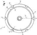
- Fig. 1 shows a suction cup according to the present invention.
- the suction cup 1 comprises a vacuum chamber or suction cup 2 and a sealing region 3.
- the suction cup is pressed against a contact surface 11 and the applied pressure force allows the air to escape from the vacuum chamber.
- the suction cup 1 consists of an elastically flexible material, in particular rubber, so that the vacuum chamber 2 can be deformed so that the air can escape. After the air has escaped from the vacuum chamber, thus creating a vacuum which can be maintained against the environment by means of the sealing region 3, in particular the sealing lip 3a in the contact region with the contact surface 11 of the suction cup 1.
- the vacuum creates an atmospheric pressure on the suction cup 1, which causes the suction cup 1 is pressed against the contact surface 11.
- This contact pressure or holding force can also be regarded as a suction force which fixes or holds the suction cup 1 on the surface or contact surface 11.
- the suction force or holding force of the suction cup 1 can also be defined.
- the means 4 for reducing the peeling force is realized as a plurality of projections 5.
- the projections are formed symmetrically spaced on a sealing region 3.
- an asymmetrical arrangement of the projections 5 can be realized.
- the projections 5 lie flat on the Anlag Chemistry 11.
- unpressurized state the state is meant in which there is no vacuum in the chamber 2. After the suction cup has been pressed onto a surface 11, the sealing region 3 forms a sealing lip in the contact region 3 a with the contact surface 11, so that the vacuum within the vacuum chamber 2 can be maintained.
- the suction cup 1 loses adhesion, as a result of which the vacuum has been dissolved by admission of air, ie a pressure equalization between the vacuum chamber 2 and the atmospheric environment has taken place.
- the contact area or the sealing lip 3a forms after the air has escaped from the vacuum chamber 2 by the contact pressure.
- the elastic properties of the material of which the suction cup 1 is made cause the projections 5 in the pressed-on state to have no contact with the contact surface 11.
- the projections or nubs 5 are formed as a circular segment 8 on the sealing region 3.
- the height of the circular segment-shaped projections 5 relative to the surface of the sealing region 3 is preferably 0.2 mm.
- the distance of the circular arc 9 of the circular segment 8 to the contact region 3a corresponds to L2 and is about 1 mm, although other values can be used.
- the circular chord 10 of the circular segment 8 extends substantially along an outer line 14 in the edge region 6 of the sealing region 3 of the suction cup 1. According to one embodiment of the present invention, the chord is approximately 4 mm.
- the suction cup 1 is circular and has a radius L1. This radius L1 additionally defines the height of the holding force or suction force of the suction cup 1. A large radius corresponds to an enlarged vacuum chamber 3, which consequently defines an enlarged vacuum region.
- Fig. 2 shows a perspective view of a suction cup according to the present invention.
- the vacuum chamber 2 of the suction cup 1 is dome-shaped and by the elastic-flexible material, a vacuum can be generated by pressing the suction cup 1 on a contact surface 11.
- the means 4 for reducing the detachment force F1 a plurality of circular segment-shaped projections 5, which are preferably formed integrally with the body of the suction cup 1.
- the suction cup 1 can be made as a rubber body with moldings 5 easily in a manufacturing step, for example by injection molding.
- the suction cup 1 further comprises a fastening means 7 which is such that the suction cup 1 can be used as a base for, for example, a kitchen appliance base 13.
- a contact area 3a forms a sealing lip on the contact surface 11, and the projections have no contact with the contact surface 11 on.
- the sealing region 3 on which the projections 5 are formed is formed such that the edge region 6 moves with its outer line 14 in the attached state of the suction cup away from the contact surface 11 or lifts off, so that the projections 5 no contact with the contact surface 11th can build up.
- the sealing lip in the contact region 3 a of the sealing region 3 ensures that no air can enter the vacuum chamber 2, in which vacuum in the attached state of the suction cup 1 can thus be maintained.
- the detachment of the suction cup 1 from a contact surface 11 is usually carried out by exerting a detachment force F1, for example in the region of the fastening means 7.
- the force F1 should counteract the suction force or holding force of the suction cup 1 on the contact surface 11.
- the detachment force F1 and the elastic properties of the suction cup material By exerting the detachment force F1 and the elastic properties of the suction cup material, the formations 5 are caused to be pressed against the abutment surface 11, so that a lever effect can be formed which reduces the detaching force in comparison with the conventional suction cups.
- Fig. 4 The operation of the simplified detachment of the suction cup 1 is explained in more detail.
- Fig. 3 is a side view of a suction cup according to the present invention.
- the suction cup 1 is shown in the unattached state and consequently the formations 5 could be in contact with a contact surface 11.
- the vacuum chamber or suction cup 2 has a dome-like structure in which a vacuum can form in the attached state.
- the fastening device 7 has a joint or a flange, on which the suction cup 1 could be fixed or fastened, for example, in a device base. This mounting flange secures the suction cup on the bottom of the device 13.
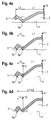
- Fig. 4a to 4d show the principle of operation of the suction cup based on a sketch.
- the suction cup 1 is shown in half to better represent the distribution of forces in the event of detachment.
- the contact surface 11, for example, the surface of a work table in the kitchen is also shown schematically.
- the suction cup 1 is shown in the attached state. That is, a vacuum has been formed in the vacuum chamber 2 and suction cup, and by this vacuum becomes a suction force or holding force on the suction cup from the atmospheric pressure exercised, so that the suction cup 1 adheres to the contact surface 11 and, for example, a kitchen appliance (not shown) or its bottom 13 stabilized or secured in operation.
- a detachment force F1 can for example be exerted in the vertical direction, wherein in principle the suction cup 1 can also be attached to a wall or an inclined surface.
- the fastening means 7 is in the Fig. 4a to 4d for the sake of simplicity not shown.
- the detachment force F1 of the elastic body of the suction cup 1 is deformed so that a rotation about the contact area or the sealing lip 3a is formed.
- the schematically illustrated projections 5 are consequently moved in the direction of the contact surface.
- the distance L2 defines the time at which the contact point 5a of the projections 5 contacts the surface 11.
- This distance L2 to the sealing lip 3a of the suction cup 1 further defines the height of the detachment force F1, which see by means of a lever structure Fig. 4c and 4d acts on the sealing lip in the contact region 3a.
- the time point is shown to which the contact point 5a of the Anformung 5 has contacted the contact surface 11, and thus arises the above-mentioned lever structure with a pivot point which coincides with the contact point 5a of the Anformung 5.
- the contact point 5a does not necessarily correspond to a single point, but rather by the elasticity of the body of the suction cup 1 or through the circular arc 9 of the respective projections 5 corresponds to a range at which the leverage effect of the detachment force F1 can begin.
- a force F2 is exerted on the sealing lip 3a, which counteracts the holding force or suction force of the suction cup 1. So that the suction cup 1 can be detached from the surface 11 by a reduced detaching force F1, according to the invention the means for reducing 4 are provided, which have been realized as formations 5 in this embodiment.
- the shows Fig. 4d the time at which the sealing lip 3a has yielded, and an air inlet ie a pressure equalization to the environment has taken place and the suction cup 1 has lost its suction or holding force.
- the reduced detachment force F2 is consequently defined by the lever action around the contact point 5a and is a function of the distance L2 between the sealing lip 3a and the circular arc 9 of the projection 5. Accordingly, the decreased peeling force F1 is defined by the arrangement of the reducing means 4 relative to the sealing lip or contact area 3a of the suction cup.
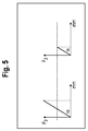
- Fig. 5 shows the principal force curve of the suction cup compared to a conventional suction cup.
- the x-axis corresponds to the power stroke with respect to the point of action, for example, the fastening means 7 of the suction cup. Due to the elasticity of the suction cup creates the stroke which is shown schematically on the x-axis of both diagrams.
- the y-axis shows the course of the detachment force F2.
- the force curve is linear to the stroke and there is no defined early time of detachment or pressure compensation by air ingress into the vacuum chamber 2.
- the means 4 for reducing the detachment force F2 causes the pressure equalization and consequently the detachment of the suction cup at a defined time, the curves being analogous up to this point in time. That up to this defined time, the suction cup 1 according to the invention provides the same holding force or stability.
- the time or value of the defined separation force is shown schematically with the help of the dashed line.
- FIG. 6 a possible application of suction cups according to the present invention.
- the suction cups 1 are fastened by means of the fastening means 7, for example, to a floor 13 of a kitchen appliance.
- the suction cups 1 act as feet and absorb the vibrations of the food processor or kitchen appliance taken in operation. If the kitchen appliance must be moved from a contact surface 11 after completion of work or for the purpose of adjustment, the force that is necessary for detachment of the device is no longer relatively high as with conventional suction cups, but has a defined value, by means of the formations. 5 or the means 4 for reducing the release force has been provided.
- the suction cup according to the invention has a defined and reduced detachment force, which improves the handling of the suction cup 1.
- a user does not have to spend a relatively high amount of effort to achieve a replacement, which is considered to be has proven particularly advantageous in the use of the suction cup as a base of an electrical device.
Landscapes
- Engineering & Computer Science (AREA)
- General Engineering & Computer Science (AREA)
- Mechanical Engineering (AREA)
- Hooks, Suction Cups, And Attachment By Adhesive Means (AREA)
- Table Equipment (AREA)
Priority Applications (2)
| Application Number | Priority Date | Filing Date | Title |
|---|---|---|---|
| PL10778927T PL2496850T3 (pl) | 2009-11-06 | 2010-10-29 | Przyssawka |
| SI201031174A SI2496850T1 (sl) | 2009-11-06 | 2010-10-29 | Prisesek |
Applications Claiming Priority (2)
| Application Number | Priority Date | Filing Date | Title |
|---|---|---|---|
| DE102009046508A DE102009046508A1 (de) | 2009-11-06 | 2009-11-06 | Saugnapf |
| PCT/EP2010/066520 WO2011054764A1 (de) | 2009-11-06 | 2010-10-29 | Saugnapf |
Publications (2)
| Publication Number | Publication Date |
|---|---|
| EP2496850A1 EP2496850A1 (de) | 2012-09-12 |
| EP2496850B1 true EP2496850B1 (de) | 2016-02-10 |
Family
ID=43365841
Family Applications (1)
| Application Number | Title | Priority Date | Filing Date |
|---|---|---|---|
| EP10778927.3A Active EP2496850B1 (de) | 2009-11-06 | 2010-10-29 | Saugnapf |
Country Status (9)
| Country | Link |
|---|---|
| EP (1) | EP2496850B1 (pl) |
| CN (1) | CN102667187B (pl) |
| DE (1) | DE102009046508A1 (pl) |
| ES (1) | ES2563175T3 (pl) |
| HU (1) | HUE028754T2 (pl) |
| PL (1) | PL2496850T3 (pl) |
| RU (1) | RU2514146C2 (pl) |
| SI (1) | SI2496850T1 (pl) |
| WO (1) | WO2011054764A1 (pl) |
Families Citing this family (4)
| Publication number | Priority date | Publication date | Assignee | Title |
|---|---|---|---|---|
| DE102016008003A1 (de) * | 2016-04-08 | 2017-10-12 | Tormaxx Gmbh | Saugnapfhalterung mit einer Saugplatte und einem Gehäuse |
| US10253803B2 (en) * | 2017-07-19 | 2019-04-09 | Helen Of Troy Limited | Suction device |
| DE102017119554A1 (de) * | 2017-08-25 | 2019-02-28 | Probst Gmbh | Vakuum-Handverlegegerät |
| RU198546U1 (ru) * | 2020-01-09 | 2020-07-15 | Николай Васильевич Местяшев | Устройство для предотвращения поступления газов из канализационных трубопроводов в помещения |
Citations (1)
| Publication number | Priority date | Publication date | Assignee | Title |
|---|---|---|---|---|
| DE202008011812U1 (de) * | 2008-09-05 | 2008-11-06 | Bohle Ag | Saugheber |
Family Cites Families (11)
| Publication number | Priority date | Publication date | Assignee | Title |
|---|---|---|---|---|
| DE2124511B1 (de) * | 1971-05-18 | 1972-05-25 | Kissing & Möllmann, 5860 Iserlohn | Saugnapf mit mehreren Dichtlippen |
| SU1014568A1 (ru) * | 1981-02-03 | 1983-04-30 | Войсковая часть 27177-В | Приспособление дл креплени изделий |
| CN2171720Y (zh) * | 1993-08-24 | 1994-07-13 | 赵永田 | 负重式吸盘 |
| CN1038156C (zh) * | 1996-10-31 | 1998-04-22 | 邹德骏 | 吸盘式挂钩和吸盘构件 |
| US6588718B2 (en) * | 2001-06-11 | 2003-07-08 | Syron Engineering & Manufacturing, L.L.C. | Bellowed suction cup |
| JP2004183879A (ja) * | 2002-12-02 | 2004-07-02 | Fumito Yamashita | 押圧だけで強吸着力発生吸盤 |
| US20060285428A1 (en) * | 2005-06-16 | 2006-12-21 | Paradise Charles S | Mixing bowl with suction devices |
| US8096537B2 (en) * | 2006-09-28 | 2012-01-17 | GM Global Technology Operations LLC | Active material based suction cups |
| US7975971B2 (en) * | 2006-11-15 | 2011-07-12 | Carnevali Jeffrey D | Suction cup device |
| CN101294598A (zh) * | 2007-04-26 | 2008-10-29 | 昆山宝木产品设计有限公司 | 强力吸盘 |
| DE102007057889A1 (de) | 2007-11-29 | 2009-06-04 | Shu-Pei Huang | Saugnapfbefestiger |
-
2009
- 2009-11-06 DE DE102009046508A patent/DE102009046508A1/de not_active Ceased
-
2010
- 2010-10-29 CN CN201080050078.4A patent/CN102667187B/zh not_active Expired - Fee Related
- 2010-10-29 PL PL10778927T patent/PL2496850T3/pl unknown
- 2010-10-29 RU RU2012121689/12A patent/RU2514146C2/ru active
- 2010-10-29 ES ES10778927.3T patent/ES2563175T3/es active Active
- 2010-10-29 HU HUE10778927A patent/HUE028754T2/en unknown
- 2010-10-29 SI SI201031174A patent/SI2496850T1/sl unknown
- 2010-10-29 WO PCT/EP2010/066520 patent/WO2011054764A1/de not_active Ceased
- 2010-10-29 EP EP10778927.3A patent/EP2496850B1/de active Active
Patent Citations (1)
| Publication number | Priority date | Publication date | Assignee | Title |
|---|---|---|---|---|
| DE202008011812U1 (de) * | 2008-09-05 | 2008-11-06 | Bohle Ag | Saugheber |
Also Published As
| Publication number | Publication date |
|---|---|
| ES2563175T3 (es) | 2016-03-11 |
| CN102667187B (zh) | 2015-09-23 |
| RU2012121689A (ru) | 2013-12-20 |
| SI2496850T1 (sl) | 2016-06-30 |
| HUE028754T2 (en) | 2016-12-28 |
| PL2496850T3 (pl) | 2016-07-29 |
| RU2514146C2 (ru) | 2014-04-27 |
| CN102667187A (zh) | 2012-09-12 |
| DE102009046508A1 (de) | 2011-05-12 |
| WO2011054764A1 (de) | 2011-05-12 |
| EP2496850A1 (de) | 2012-09-12 |
Similar Documents
| Publication | Publication Date | Title |
|---|---|---|
| EP2941798B1 (de) | Umweltdichtes steckverbindergehäuse | |
| DE202019005606U1 (de) | Vakuumgreifer | |
| EP2526295B1 (de) | Elastomerfeder mit mechanisch regulierbarer steifigkeit | |
| EP2496850B1 (de) | Saugnapf | |
| EP2385282B1 (de) | Ventilanordnung mit einem Basisteil und einem Einsatzteil | |
| DE102011007247A1 (de) | Wischblattadaptervorrichtung | |
| DE102005062797A1 (de) | Sprühapparat | |
| EP0910745B1 (de) | Membrane für eine membranpumpe | |
| DE202004010526U1 (de) | Anordnung mit einem in einer Ausnehmung einer Wand befestigbaren Lüfter | |
| DE102013110064A1 (de) | Tastenmodul und Aufsteckelement für ein Tastenmodul | |
| EP1768815B1 (de) | Befestigungselement zur reibschweissverbindung mit einem flächigen bauteil | |
| EP2212568B1 (de) | Saugnapfbefestiger | |
| DE10235799A1 (de) | Kunststoffmutter zur Anbringung an einem Bauteil | |
| EP0367287A1 (de) | Membranventil mit einer von einem Ventildeckel abgestützten elastischen Membrane | |
| DE3221794C2 (pl) | ||
| EP2175462B1 (de) | Abgedichteter Schalter | |
| DE102013104469A1 (de) | Vorrichtung zur grossflächigen elektrischen und/oder thermischen Kontaktierung eines Wafers | |
| DE102017219436B3 (de) | Membran-Polymeraktuator, Herstellungsverfahren dafür und zugehörige Aktuatorbaugruppe | |
| DE102010048399B4 (de) | Verfahren zur Herstellung eines Hybridbauteils und Pressenwerkzeug zur Herstellung eines Kraftfahrzeughybridbauteils | |
| EP3292592A1 (de) | Batterieklemme und verfahren zur herstellung einer batterieklemme | |
| DE102009016625A1 (de) | Saugheber zur temporären Fixierung an einer Werkstückoberfläche | |
| DE202016000523U1 (de) | Saughaltevorrichtung | |
| DE202014103970U1 (de) | Aufbau einer Ansaugscheibe und deren Unterlage | |
| DE202007010003U1 (de) | Tastenanordnung mit Federgelenk und mit Kegelstumpffeder | |
| DE202018103437U1 (de) | Deckeldichtung |
Legal Events
| Date | Code | Title | Description |
|---|---|---|---|
| PUAI | Public reference made under article 153(3) epc to a published international application that has entered the european phase |
Free format text: ORIGINAL CODE: 0009012 |
|
| 17P | Request for examination filed |
Effective date: 20120606 |
|
| AK | Designated contracting states |
Kind code of ref document: A1 Designated state(s): AL AT BE BG CH CY CZ DE DK EE ES FI FR GB GR HR HU IE IS IT LI LT LU LV MC MK MT NL NO PL PT RO RS SE SI SK SM TR |
|
| DAX | Request for extension of the european patent (deleted) | ||
| 17Q | First examination report despatched |
Effective date: 20130423 |
|
| RAP1 | Party data changed (applicant data changed or rights of an application transferred) |
Owner name: BSH HAUSGERAETE GMBH |
|
| GRAP | Despatch of communication of intention to grant a patent |
Free format text: ORIGINAL CODE: EPIDOSNIGR1 |
|
| INTG | Intention to grant announced |
Effective date: 20150820 |
|
| GRAS | Grant fee paid |
Free format text: ORIGINAL CODE: EPIDOSNIGR3 |
|
| GRAA | (expected) grant |
Free format text: ORIGINAL CODE: 0009210 |
|
| AK | Designated contracting states |
Kind code of ref document: B1 Designated state(s): AL AT BE BG CH CY CZ DE DK EE ES FI FR GB GR HR HU IE IS IT LI LT LU LV MC MK MT NL NO PL PT RO RS SE SI SK SM TR |
|
| REG | Reference to a national code |
Ref country code: GB Ref legal event code: FG4D Free format text: NOT ENGLISH |
|
| REG | Reference to a national code |
Ref country code: AT Ref legal event code: REF Ref document number: 774802 Country of ref document: AT Kind code of ref document: T Effective date: 20160215 Ref country code: CH Ref legal event code: EP |
|
| REG | Reference to a national code |
Ref country code: IE Ref legal event code: FG4D Free format text: LANGUAGE OF EP DOCUMENT: GERMAN |
|
| REG | Reference to a national code |
Ref country code: ES Ref legal event code: FG2A Ref document number: 2563175 Country of ref document: ES Kind code of ref document: T3 Effective date: 20160311 |
|
| REG | Reference to a national code |
Ref country code: DE Ref legal event code: R096 Ref document number: 502010011051 Country of ref document: DE |
|
| REG | Reference to a national code |
Ref country code: SE Ref legal event code: TRGR |
|
| REG | Reference to a national code |
Ref country code: LT Ref legal event code: MG4D |
|
| REG | Reference to a national code |
Ref country code: NL Ref legal event code: MP Effective date: 20160210 |
|
| PG25 | Lapsed in a contracting state [announced via postgrant information from national office to epo] |
Ref country code: FI Free format text: LAPSE BECAUSE OF FAILURE TO SUBMIT A TRANSLATION OF THE DESCRIPTION OR TO PAY THE FEE WITHIN THE PRESCRIBED TIME-LIMIT Effective date: 20160210 Ref country code: HR Free format text: LAPSE BECAUSE OF FAILURE TO SUBMIT A TRANSLATION OF THE DESCRIPTION OR TO PAY THE FEE WITHIN THE PRESCRIBED TIME-LIMIT Effective date: 20160210 Ref country code: NO Free format text: LAPSE BECAUSE OF FAILURE TO SUBMIT A TRANSLATION OF THE DESCRIPTION OR TO PAY THE FEE WITHIN THE PRESCRIBED TIME-LIMIT Effective date: 20160510 |
|
| PG25 | Lapsed in a contracting state [announced via postgrant information from national office to epo] |
Ref country code: LV Free format text: LAPSE BECAUSE OF FAILURE TO SUBMIT A TRANSLATION OF THE DESCRIPTION OR TO PAY THE FEE WITHIN THE PRESCRIBED TIME-LIMIT Effective date: 20160210 Ref country code: PT Free format text: LAPSE BECAUSE OF FAILURE TO SUBMIT A TRANSLATION OF THE DESCRIPTION OR TO PAY THE FEE WITHIN THE PRESCRIBED TIME-LIMIT Effective date: 20160613 Ref country code: RS Free format text: LAPSE BECAUSE OF FAILURE TO SUBMIT A TRANSLATION OF THE DESCRIPTION OR TO PAY THE FEE WITHIN THE PRESCRIBED TIME-LIMIT Effective date: 20160210 Ref country code: NL Free format text: LAPSE BECAUSE OF FAILURE TO SUBMIT A TRANSLATION OF THE DESCRIPTION OR TO PAY THE FEE WITHIN THE PRESCRIBED TIME-LIMIT Effective date: 20160210 Ref country code: LT Free format text: LAPSE BECAUSE OF FAILURE TO SUBMIT A TRANSLATION OF THE DESCRIPTION OR TO PAY THE FEE WITHIN THE PRESCRIBED TIME-LIMIT Effective date: 20160210 Ref country code: IS Free format text: LAPSE BECAUSE OF FAILURE TO SUBMIT A TRANSLATION OF THE DESCRIPTION OR TO PAY THE FEE WITHIN THE PRESCRIBED TIME-LIMIT Effective date: 20160610 |
|
| REG | Reference to a national code |
Ref country code: GR Ref legal event code: EP Ref document number: 20160400734 Country of ref document: GR Effective date: 20160601 |
|
| REG | Reference to a national code |
Ref country code: FR Ref legal event code: PLFP Year of fee payment: 7 |
|
| PG25 | Lapsed in a contracting state [announced via postgrant information from national office to epo] |
Ref country code: EE Free format text: LAPSE BECAUSE OF FAILURE TO SUBMIT A TRANSLATION OF THE DESCRIPTION OR TO PAY THE FEE WITHIN THE PRESCRIBED TIME-LIMIT Effective date: 20160210 Ref country code: DK Free format text: LAPSE BECAUSE OF FAILURE TO SUBMIT A TRANSLATION OF THE DESCRIPTION OR TO PAY THE FEE WITHIN THE PRESCRIBED TIME-LIMIT Effective date: 20160210 |
|
| REG | Reference to a national code |
Ref country code: DE Ref legal event code: R097 Ref document number: 502010011051 Country of ref document: DE |
|
| PG25 | Lapsed in a contracting state [announced via postgrant information from national office to epo] |
Ref country code: SK Free format text: LAPSE BECAUSE OF FAILURE TO SUBMIT A TRANSLATION OF THE DESCRIPTION OR TO PAY THE FEE WITHIN THE PRESCRIBED TIME-LIMIT Effective date: 20160210 Ref country code: CZ Free format text: LAPSE BECAUSE OF FAILURE TO SUBMIT A TRANSLATION OF THE DESCRIPTION OR TO PAY THE FEE WITHIN THE PRESCRIBED TIME-LIMIT Effective date: 20160210 Ref country code: RO Free format text: LAPSE BECAUSE OF FAILURE TO SUBMIT A TRANSLATION OF THE DESCRIPTION OR TO PAY THE FEE WITHIN THE PRESCRIBED TIME-LIMIT Effective date: 20160210 Ref country code: SM Free format text: LAPSE BECAUSE OF FAILURE TO SUBMIT A TRANSLATION OF THE DESCRIPTION OR TO PAY THE FEE WITHIN THE PRESCRIBED TIME-LIMIT Effective date: 20160210 |
|
| PLBE | No opposition filed within time limit |
Free format text: ORIGINAL CODE: 0009261 |
|
| STAA | Information on the status of an ep patent application or granted ep patent |
Free format text: STATUS: NO OPPOSITION FILED WITHIN TIME LIMIT |
|
| REG | Reference to a national code |
Ref country code: HU Ref legal event code: AG4A Ref document number: E028754 Country of ref document: HU |
|
| 26N | No opposition filed |
Effective date: 20161111 |
|
| PG25 | Lapsed in a contracting state [announced via postgrant information from national office to epo] |
Ref country code: BE Free format text: LAPSE BECAUSE OF NON-PAYMENT OF DUE FEES Effective date: 20161031 Ref country code: BG Free format text: LAPSE BECAUSE OF FAILURE TO SUBMIT A TRANSLATION OF THE DESCRIPTION OR TO PAY THE FEE WITHIN THE PRESCRIBED TIME-LIMIT Effective date: 20160510 |
|
| REG | Reference to a national code |
Ref country code: CH Ref legal event code: PL |
|
| GBPC | Gb: european patent ceased through non-payment of renewal fee |
Effective date: 20161029 |
|
| REG | Reference to a national code |
Ref country code: IE Ref legal event code: MM4A |
|
| PG25 | Lapsed in a contracting state [announced via postgrant information from national office to epo] |
Ref country code: LI Free format text: LAPSE BECAUSE OF NON-PAYMENT OF DUE FEES Effective date: 20161031 Ref country code: CH Free format text: LAPSE BECAUSE OF NON-PAYMENT OF DUE FEES Effective date: 20161031 Ref country code: GB Free format text: LAPSE BECAUSE OF NON-PAYMENT OF DUE FEES Effective date: 20161029 |
|
| PG25 | Lapsed in a contracting state [announced via postgrant information from national office to epo] |
Ref country code: LU Free format text: LAPSE BECAUSE OF NON-PAYMENT OF DUE FEES Effective date: 20161029 |
|
| REG | Reference to a national code |
Ref country code: FR Ref legal event code: PLFP Year of fee payment: 8 |
|
| PG25 | Lapsed in a contracting state [announced via postgrant information from national office to epo] |
Ref country code: IE Free format text: LAPSE BECAUSE OF NON-PAYMENT OF DUE FEES Effective date: 20161029 |
|
| REG | Reference to a national code |
Ref country code: BE Ref legal event code: MM Effective date: 20161031 |
|
| REG | Reference to a national code |
Ref country code: AT Ref legal event code: MM01 Ref document number: 774802 Country of ref document: AT Kind code of ref document: T Effective date: 20161029 |
|
| PG25 | Lapsed in a contracting state [announced via postgrant information from national office to epo] |
Ref country code: AT Free format text: LAPSE BECAUSE OF NON-PAYMENT OF DUE FEES Effective date: 20161029 |
|
| PG25 | Lapsed in a contracting state [announced via postgrant information from national office to epo] |
Ref country code: CY Free format text: LAPSE BECAUSE OF FAILURE TO SUBMIT A TRANSLATION OF THE DESCRIPTION OR TO PAY THE FEE WITHIN THE PRESCRIBED TIME-LIMIT Effective date: 20160210 |
|
| PG25 | Lapsed in a contracting state [announced via postgrant information from national office to epo] |
Ref country code: MC Free format text: LAPSE BECAUSE OF FAILURE TO SUBMIT A TRANSLATION OF THE DESCRIPTION OR TO PAY THE FEE WITHIN THE PRESCRIBED TIME-LIMIT Effective date: 20160210 Ref country code: TR Free format text: LAPSE BECAUSE OF FAILURE TO SUBMIT A TRANSLATION OF THE DESCRIPTION OR TO PAY THE FEE WITHIN THE PRESCRIBED TIME-LIMIT Effective date: 20160210 Ref country code: MT Free format text: LAPSE BECAUSE OF FAILURE TO SUBMIT A TRANSLATION OF THE DESCRIPTION OR TO PAY THE FEE WITHIN THE PRESCRIBED TIME-LIMIT Effective date: 20160210 Ref country code: MK Free format text: LAPSE BECAUSE OF FAILURE TO SUBMIT A TRANSLATION OF THE DESCRIPTION OR TO PAY THE FEE WITHIN THE PRESCRIBED TIME-LIMIT Effective date: 20160210 |
|
| REG | Reference to a national code |
Ref country code: FR Ref legal event code: PLFP Year of fee payment: 9 |
|
| PG25 | Lapsed in a contracting state [announced via postgrant information from national office to epo] |
Ref country code: AL Free format text: LAPSE BECAUSE OF FAILURE TO SUBMIT A TRANSLATION OF THE DESCRIPTION OR TO PAY THE FEE WITHIN THE PRESCRIBED TIME-LIMIT Effective date: 20160210 |
|
| PGFP | Annual fee paid to national office [announced via postgrant information from national office to epo] |
Ref country code: GR Payment date: 20231019 Year of fee payment: 14 |
|
| PGFP | Annual fee paid to national office [announced via postgrant information from national office to epo] |
Ref country code: ES Payment date: 20231117 Year of fee payment: 14 |
|
| PGFP | Annual fee paid to national office [announced via postgrant information from national office to epo] |
Ref country code: SI Payment date: 20231019 Year of fee payment: 14 Ref country code: SE Payment date: 20231025 Year of fee payment: 14 Ref country code: IT Payment date: 20231031 Year of fee payment: 14 Ref country code: HU Payment date: 20231019 Year of fee payment: 14 |
|
| PGFP | Annual fee paid to national office [announced via postgrant information from national office to epo] |
Ref country code: PL Payment date: 20231013 Year of fee payment: 14 |
|
| REG | Reference to a national code |
Ref country code: SE Ref legal event code: EUG |
|
| PG25 | Lapsed in a contracting state [announced via postgrant information from national office to epo] |
Ref country code: HU Free format text: LAPSE BECAUSE OF NON-PAYMENT OF DUE FEES Effective date: 20241030 |
|
| PG25 | Lapsed in a contracting state [announced via postgrant information from national office to epo] |
Ref country code: GR Free format text: LAPSE BECAUSE OF NON-PAYMENT OF DUE FEES Effective date: 20250512 |
|
| REG | Reference to a national code |
Ref country code: SI Ref legal event code: KO00 Effective date: 20241030 |
|
| PG25 | Lapsed in a contracting state [announced via postgrant information from national office to epo] |
Ref country code: SE Free format text: LAPSE BECAUSE OF NON-PAYMENT OF DUE FEES Effective date: 20241030 Ref country code: IT Free format text: LAPSE BECAUSE OF NON-PAYMENT OF DUE FEES Effective date: 20241029 |
|
| REG | Reference to a national code |
Ref country code: ES Ref legal event code: FD2A Effective date: 20251205 |
|
| PGFP | Annual fee paid to national office [announced via postgrant information from national office to epo] |
Ref country code: DE Payment date: 20251031 Year of fee payment: 16 |
|
| PGFP | Annual fee paid to national office [announced via postgrant information from national office to epo] |
Ref country code: FR Payment date: 20251022 Year of fee payment: 16 |
|
| PG25 | Lapsed in a contracting state [announced via postgrant information from national office to epo] |
Ref country code: ES Free format text: LAPSE BECAUSE OF NON-PAYMENT OF DUE FEES Effective date: 20241030 |