EP2496794B1 - Turbomachine with axial compression or expansion - Google Patents
Turbomachine with axial compression or expansion Download PDFInfo
- Publication number
- EP2496794B1 EP2496794B1 EP10771762.1A EP10771762A EP2496794B1 EP 2496794 B1 EP2496794 B1 EP 2496794B1 EP 10771762 A EP10771762 A EP 10771762A EP 2496794 B1 EP2496794 B1 EP 2496794B1
- Authority
- EP
- European Patent Office
- Prior art keywords
- end wall
- blade
- flow
- turbomachine
- guide surfaces
- Prior art date
- Legal status (The legal status is an assumption and is not a legal conclusion. Google has not performed a legal analysis and makes no representation as to the accuracy of the status listed.)
- Not-in-force
Links
Images

Classifications
-
- F—MECHANICAL ENGINEERING; LIGHTING; HEATING; WEAPONS; BLASTING
- F01—MACHINES OR ENGINES IN GENERAL; ENGINE PLANTS IN GENERAL; STEAM ENGINES
- F01D—NON-POSITIVE DISPLACEMENT MACHINES OR ENGINES, e.g. STEAM TURBINES
- F01D5/00—Blades; Blade-carrying members; Heating, heat-insulating, cooling or antivibration means on the blades or the members
- F01D5/12—Blades
- F01D5/14—Form or construction
- F01D5/141—Shape, i.e. outer, aerodynamic form
- F01D5/145—Means for influencing boundary layers or secondary circulations
-
- F—MECHANICAL ENGINEERING; LIGHTING; HEATING; WEAPONS; BLASTING
- F01—MACHINES OR ENGINES IN GENERAL; ENGINE PLANTS IN GENERAL; STEAM ENGINES
- F01D—NON-POSITIVE DISPLACEMENT MACHINES OR ENGINES, e.g. STEAM TURBINES
- F01D9/00—Stators
- F01D9/02—Nozzles; Nozzle boxes; Stator blades; Guide conduits, e.g. individual nozzles
- F01D9/04—Nozzles; Nozzle boxes; Stator blades; Guide conduits, e.g. individual nozzles forming ring or sector
- F01D9/041—Nozzles; Nozzle boxes; Stator blades; Guide conduits, e.g. individual nozzles forming ring or sector using blades
-
- F—MECHANICAL ENGINEERING; LIGHTING; HEATING; WEAPONS; BLASTING
- F04—POSITIVE - DISPLACEMENT MACHINES FOR LIQUIDS; PUMPS FOR LIQUIDS OR ELASTIC FLUIDS
- F04D—NON-POSITIVE-DISPLACEMENT PUMPS
- F04D29/00—Details, component parts, or accessories
- F04D29/66—Combating cavitation, whirls, noise, vibration or the like; Balancing
- F04D29/68—Combating cavitation, whirls, noise, vibration or the like; Balancing by influencing boundary layers
- F04D29/681—Combating cavitation, whirls, noise, vibration or the like; Balancing by influencing boundary layers especially adapted for elastic fluid pumps
-
- F—MECHANICAL ENGINEERING; LIGHTING; HEATING; WEAPONS; BLASTING
- F05—INDEXING SCHEMES RELATING TO ENGINES OR PUMPS IN VARIOUS SUBCLASSES OF CLASSES F01-F04
- F05D—INDEXING SCHEME FOR ASPECTS RELATING TO NON-POSITIVE-DISPLACEMENT MACHINES OR ENGINES, GAS-TURBINES OR JET-PROPULSION PLANTS
- F05D2240/00—Components
- F05D2240/10—Stators
- F05D2240/12—Fluid guiding means, e.g. vanes
- F05D2240/121—Fluid guiding means, e.g. vanes related to the leading edge of a stator vane
-
- F—MECHANICAL ENGINEERING; LIGHTING; HEATING; WEAPONS; BLASTING
- F05—INDEXING SCHEMES RELATING TO ENGINES OR PUMPS IN VARIOUS SUBCLASSES OF CLASSES F01-F04
- F05D—INDEXING SCHEME FOR ASPECTS RELATING TO NON-POSITIVE-DISPLACEMENT MACHINES OR ENGINES, GAS-TURBINES OR JET-PROPULSION PLANTS
- F05D2240/00—Components
- F05D2240/10—Stators
- F05D2240/12—Fluid guiding means, e.g. vanes
- F05D2240/127—Vortex generators, turbulators, or the like, for mixing
-
- F—MECHANICAL ENGINEERING; LIGHTING; HEATING; WEAPONS; BLASTING
- F05—INDEXING SCHEMES RELATING TO ENGINES OR PUMPS IN VARIOUS SUBCLASSES OF CLASSES F01-F04
- F05D—INDEXING SCHEME FOR ASPECTS RELATING TO NON-POSITIVE-DISPLACEMENT MACHINES OR ENGINES, GAS-TURBINES OR JET-PROPULSION PLANTS
- F05D2240/00—Components
- F05D2240/20—Rotors
- F05D2240/30—Characteristics of rotor blades, i.e. of any element transforming dynamic fluid energy to or from rotational energy and being attached to a rotor
- F05D2240/303—Characteristics of rotor blades, i.e. of any element transforming dynamic fluid energy to or from rotational energy and being attached to a rotor related to the leading edge of a rotor blade
-
- F—MECHANICAL ENGINEERING; LIGHTING; HEATING; WEAPONS; BLASTING
- F05—INDEXING SCHEMES RELATING TO ENGINES OR PUMPS IN VARIOUS SUBCLASSES OF CLASSES F01-F04
- F05D—INDEXING SCHEME FOR ASPECTS RELATING TO NON-POSITIVE-DISPLACEMENT MACHINES OR ENGINES, GAS-TURBINES OR JET-PROPULSION PLANTS
- F05D2270/00—Control
- F05D2270/01—Purpose of the control system
- F05D2270/17—Purpose of the control system to control boundary layer
-
- Y—GENERAL TAGGING OF NEW TECHNOLOGICAL DEVELOPMENTS; GENERAL TAGGING OF CROSS-SECTIONAL TECHNOLOGIES SPANNING OVER SEVERAL SECTIONS OF THE IPC; TECHNICAL SUBJECTS COVERED BY FORMER USPC CROSS-REFERENCE ART COLLECTIONS [XRACs] AND DIGESTS
- Y02—TECHNOLOGIES OR APPLICATIONS FOR MITIGATION OR ADAPTATION AGAINST CLIMATE CHANGE
- Y02T—CLIMATE CHANGE MITIGATION TECHNOLOGIES RELATED TO TRANSPORTATION
- Y02T50/00—Aeronautics or air transport
- Y02T50/60—Efficient propulsion technologies, e.g. for aircraft
Definitions
- the invention relates to a turbomachinery with axial compression or expansion, with a ring of blades whose radially outer ends are connected to an annular end wall and each having a leading edge, a trailing edge, a pressure side and a suction side.
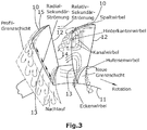
- FIG. 3 shows the essential secondary flows and vortex structures as they form in a compressor grid. It also includes secondary flows which may be due to a radial gap between the blade and the radially outer end wall.
- FIG. 3 two blades 10 of a blade ring are shown.
- the vanes are connected at their radially inner ends to a hub 11 and at their radially outer ends to an outer ring forming the end wall and not shown in the drawing.
- the blades thus form a blade grid, which can form a stator or a rotor of a compressor.
- the blades 10 each have a leading edge 12, a trailing edge 13, a pressure side 14 and a suction side 15.
- the pressure side 14 is concave and the suction side 15 is convex.
- a turbomachine is described in US Pat. No. 6,419,446 B1 , This turbomachine is a gas turbine. At the leading edges of the blades join in the transition regions to the end walls Abweiskeile, each tapering in the upstream direction.
- the deflector wedges have convexly curved guide surfaces. They form, so to speak, "shoes" which protrude forward at the end regions of the leading edge.
- Abweiskeile with straight or concave baffles are in DE 28 41 616 A1 , which discloses a turbomachine according to the preamble of patent claim 1.
- turbomachine is described as axial compressor in DE 198 34 647 C2 .
- This axial compressor has a ring of blades which are connected at their outer ends to an end wall.
- auxiliary wings are arranged, which protrude from the suction side of the blade and are employed against the local flow prevailing at the relevant point, whereby is induced.
- the auxiliary wing Since the auxiliary wing is mounted in the area of the corner flow, it influences the corner flow by supplying fast-flowing fluid from the outer flow along the blade surface associated with the auxiliary wing to the slow corner flow due to a rotational movement, accelerating it and thus preventing it from detaching. Further, the auxiliary wing has the effect of channeling and thereby accelerating the corner flow.
- the auxiliary wing is caused to act as a fence which prevents slow flowing fluid of the corner flow from mixing with the faster flow around the blade center.
- the invention has for its object to provide a turbomachine in which the total pressure losses are reduced at the blade passage with relatively simple means, whereby an increase in the efficiency is given.
- the turbomachine according to the invention has the features of claim 1. It provides that the height of the guide surfaces with respect to the end wall decreases from a common peak point downstream.
- the invention is based on the idea of specifically influencing the formation and propagation of the channel vortex and the transverse flow on the end wall by generating two strong vortices.
- the eddies are going through generates the Abweiskeil as a pair directly in front of Schaufeldanströmkante.
- This vortex pair consists of a suction-side and a pressure-side vortex.
- the direction of rotation of the suction-side vortex is such that it rotates in the region of the end wall against the transverse flow and deflects it in the front region of the blade. In this way, the accumulation of low-energy boundary layer material in the corner region is reduced and the onset of delamination is delayed.
- the invention is based essentially on the utilization or replacement of existing flow structures in the edge zone region of a compressor grille, since the weak horseshoe vortex is superimposed by the new vortex pair.
- active influencing measures no additional energy is needed, which is introduced into the flow, but the existing energy of the flow is deflected and used for flow control.
- the generated vortexes are not intended to achieve mixing or energizing of the boundary layer, but rather to deflect and direct the flow in a targeted manner. This means that the new influencing method does not work against the characteristic structures of the boundary zone flow, which generally leads to additional losses, but that the existing flow energy is deflected.
- the generation of the vortex pair can be realized even by a small modification to the end wall and is thus feasible with low design and manufacturing effort. Due to the simplicity of the geometric shape of the end wall modification, adaptation to various blushes, inflow boundary layers and work areas of compressor grids can be easily made.
- baffles begin at a common bow line that rises concave from the end wall so as to impart a small flow to the flow Resists flow resistance and causes no significant own vortex formation.
- the baffles of the deflector wedge are concave shaped to create oppositely rotating vortices.
- concave vanes are not necessarily required to achieve the effect of the present invention.
- the fins can also be flat, for example.
- the maximum height of the Abweiskeiles is preferably 5 - 8% of the radial blade length. It depends largely on the specific geometry of the blades. The invention is applicable to straight blades as well as to bow blades in which the blades have an arcuate radial course.
- the Abweiskeil forms a kind of Vorkeil, which is pre-set in the end wall portion of the leading edge of the blade. He passes in this area, the flow past the leading edge of the blade and at the same time away from the end wall.
- the Abweiskeil may be formed as a hollow wedge, which includes a space into which the leading edge of the blade protrudes.
- the turbomachine according to the invention comprises both axial compressors and axial turbines.
- FIG. 1 two blades 10 are shown, which together with other blades form a ring and project radially from a hub (not shown).
- the radially outer ends of the blades 10 are connected to an annular end wall 16. Hub and end wall together with the blades form the so-called blade grid.
- Each blade 10 has a leading leading edge 12 and a trailing trailing edge 13.
- the underside forms a pressure side 14 and the top forms a suction side 15.
- the entire blade grid rotates. In a stator, however, the entire blade grid is stationary and it is flowed by an air flow. In FIG. 1 the flow is denoted by an arrow 17.
- a Abweiskeil 20 is attached to the end wall 16 before the respective leading edge 12.
- the Abweiskeil has two downstream diverging vanes 21, 22, which unite at the front end in a common bow line 23, as is apparent from FIG. 2 is apparent.
- the bow line 23 progressively increases from the end wall 16 and terminates at a peak 24 where the deflector wedge is at its maximum height. Downstream of this peak, the height of the fins 21, 22 steadily decreases to zero.
- the fins 21, 22 are concave shaped to have a partial tube contour. Between the guide surfaces 21, 22, a free space 25 is provided, into which the leading edge 12 of the adjacent blade protrudes. But it is also possible that the blade is located at a distance behind the Abweiskeil.
- FIG. 1 The vortices generated by the guide surfaces 21, 22 are also shown. It is the pressure-side vortex 30, which is generated by the guide surface 21 and the suction-side vortex 31, which is generated by the guide surface 22. In the Figures 1 and 2 are also the directions of rotation of the respective vortex drawn. Out FIG. 1 it can be seen that the suction-side vortex 31 deflects the transverse flow in the front region of the blade due to its direction of rotation on the end wall 16. The formation of the vortex system of pressure-side vortex 30, balance vortex and channel vortex is also in FIG. 1 shown. In addition, the direction of the deflection and guidance of the channel vortex is clarified by the pressure-side vortex.
Description
Die Erfindung betrifft eine Turbomaschine mit axialer Verdichtung oder Expansion, mit einem Kranz von Schaufeln, deren radial äußere Enden mit einer ringförmigen Endwand verbunden sind und die jeweils eine Anströmkante, eine Abströmkante, eine Druckseite und eine Saugseite aufweisen.The invention relates to a turbomachinery with axial compression or expansion, with a ring of blades whose radially outer ends are connected to an annular end wall and each having a leading edge, a trailing edge, a pressure side and a suction side.
Bei der Durchströmung von Leit- und Laufschaufelgittern von Turbomaschinen kommt es zu Verlusten, welche den Wirkungsgrad der Schaufelreihen und damit auch der gesamten Maschine begrenzen. Diese Strömungsverluste lassen sich im wesentlichen in Reibungsverluste an den Oberflächen (Schaufel sowie Naben- und Gehäusewände) und Verluste aufgrund von Sekundärströmungen im Randzonenbereich der Schaufelgitter unterteilen. Speziell die Verringerung der Sekundärströmungsverluste ist ein wichtiger Bestandteil der Forschung auf dem Gebiet der Verdichtertechnologie, da vor dem Hintergrund einer immer weiter steigenden Nachfrage an Energie und eines stetig zunehmenden Flugverkehrsaufkommens der Belastung der Umwelt durch CO2 nur durch effizientere Gasturbinen und Flugtriebwerke entgegengewirkt werden kann.The flow through the guide and blade lattices of turbomachines results in losses which limit the efficiency of the blade rows and thus also of the entire machine. These flow losses can be subdivided essentially into friction losses on the surfaces (blade and hub and housing walls) and losses due to secondary flows in the edge zone region of the blade grids. Especially the reduction of Secondary flow losses are an important part of research in the field of compressor technology because, against a backdrop of ever-increasing demand for energy and ever-increasing air traffic, the environmental impact of CO 2 can only be counteracted by more efficient gas turbines and aircraft engines.
Die Beeinflussung und Verringerung der Sekundärströmung und der aus ihr resultierenden Verluste ist speziell in der Verdichteraerodynamik in den letzten Jahrzehnten eines der zentralen Themen der Forschung gewesen. Da gerade die Strömungsverhältnisse in den Randzonen zwischen den Schaufeln und den Naben- und Gehäusewänden durch komplexe Wirbelsysteme und Sekundärströmungen geprägt sind, stellt sich deren gezielte Beeinflussung als wissenschaftliche Herausforderung dar.Influencing and reducing secondary flow and the resulting losses has been one of the central topics of research, especially in compressor aerodynamics in recent decades. Since the flow conditions in the edge zones between the blades and the hub and housing walls are characterized by complex vortex systems and secondary flows, their targeted influencing poses a scientific challenge.
Die
Eine Turbomaschine ist beschrieben in
Ferner ist eine Turbomaschine als Axialverdichter beschrieben in
Dieser Axialverdichter hat einen Kranz von Schaufeln, die an ihren äußeren Enden mit einer Endwand verbunden sind. Auf den Schaufeln sind Hilfsflügel angeordnet, die von der Saugseite der Schaufel abstehen und gegen die an der betreffenden Stelle herrschende lokale Strömung angestellt sind, wodurch sich induziert wird. Da der Hilfsflügel im Bereich der Eckenströmung angebracht ist, beeinflusst er die Eckenströmung, indem er aufgrund einer Drehbewegung schnellströmendes Fluid von der Außenströmung entlang der dem Hilfsflügel zugeordneten Schaufeloberfläche der langsamen Eckenströmung zuführt, diese beschleunigt und so am Ablösen hindert. Ferner hat der Hilfsflügel die Wirkung, dass er die Eckenströmung kanalisiert und dadurch beschleunigt. Außerdem wird bewirkt, dass der Hilfsflügel als Zaun wirkt, der verhindert, dass langsam strömendes Fluid der Eckenströmung sich mit der schnelleren Umströmung der Schaufelmitte vermischen kann.This axial compressor has a ring of blades which are connected at their outer ends to an end wall. On the blades auxiliary wings are arranged, which protrude from the suction side of the blade and are employed against the local flow prevailing at the relevant point, whereby is induced. Since the auxiliary wing is mounted in the area of the corner flow, it influences the corner flow by supplying fast-flowing fluid from the outer flow along the blade surface associated with the auxiliary wing to the slow corner flow due to a rotational movement, accelerating it and thus preventing it from detaching. Further, the auxiliary wing has the effect of channeling and thereby accelerating the corner flow. In addition, the auxiliary wing is caused to act as a fence which prevents slow flowing fluid of the corner flow from mixing with the faster flow around the blade center.
In
Die bekannten Lösungen erfordern einen erhöhten Fertigungsaufwand. Häufig ist die Überführung des experimentellen Status in die praktische Anwendung nicht vollständig geklärt, da noch strukturelle Festigkeit und Lebensdauer der Bauteile, die manchmal stark belastet sind, verbessert werden müssen.The known solutions require increased production costs. Often, the transition from experimental status to practical application is not fully understood as structural strength and life of the components, which are sometimes heavily loaded, still need to be improved.
Der Erfindung liegt die Aufgabe zugrunde, eine Turbomaschine zu schaffen, bei der mit relativ einfachen Mitteln die Totaldruckverluste an der Schaufelpassage reduziert sind, wodurch eine Steigerung des Wirkungsgrades gegeben ist.The invention has for its object to provide a turbomachine in which the total pressure losses are reduced at the blade passage with relatively simple means, whereby an increase in the efficiency is given.
Die erfindungsgemäße Turbomaschine hat die Merkmale des Patentanspruchs 1. Sie sieht vor , dass die Höhe der Leitflächen in Bezug auf die Endwand sich von einem gemeinsamen Gipfelpunkt aus stromabwärts verringert.The turbomachine according to the invention has the features of claim 1. It provides that the height of the guide surfaces with respect to the end wall decreases from a common peak point downstream.
Die Erfindung basiert auf dem Gedanken, die Entstehung und Ausbildung bzw. Ausbreitung des Kanalwirbels und die Querströmung an der Endwand durch Erzeugung zweier starker Wirbel gezielt zu beeinflussen. Die Wirbel werden durch den Abweiskeil als Paar direkt vor der Schaufelanströmkante erzeugt. Dieses Wirbelpaar besteht aus einem saugseitigen und einem druckseitigen Wirbel. Die Rotationsrichtung des saugseitigen Wirbels ist so, dass er im Bereich der Endwand entgegen der Querströmung rotiert und diese im vorderen Bereich der Schaufel ablenkt. Auf diese Weise wird die Ansammlung von energiearmem Grenzschichtmaterial im Eckenbereich verringert und das Einsetzen der Ablösung wird verzögert.The invention is based on the idea of specifically influencing the formation and propagation of the channel vortex and the transverse flow on the end wall by generating two strong vortices. The eddies are going through generates the Abweiskeil as a pair directly in front of Schaufeldanströmkante. This vortex pair consists of a suction-side and a pressure-side vortex. The direction of rotation of the suction-side vortex is such that it rotates in the region of the end wall against the transverse flow and deflects it in the front region of the blade. In this way, the accumulation of low-energy boundary layer material in the corner region is reduced and the onset of delamination is delayed.
Die Erfindung beruht im wesentlichen auf der Ausnutzung bzw. Ersetzung vorhandener Strömungsstrukturen im Randzonenbereich eines Verdichtergitters, da der schwache Hufeisenwirbel durch das neue Wirbelpaar überlagert wird. Im Gegensatz zu aktiven Beeinflussungsmaßnahmen wird keine zusätzliche Energie benötigt, welche in die Strömung eingebracht wird, sondern die vorhandene Energie der Strömung wird umgelenkt und zur Strömungsbeeinflussung genutzt. Anders als beim Einsatz von Wirbelgeneratoren soll durch die erzeugten Wirbel keine Durchmischung bzw. Energetisierung der Grenzschicht erreicht werden, sondern die Strömung soll gezielt abgelenkt und geleitet werden. Das bedeutet, dass durch die neue Beeinflussungsmethode nicht gegen die charakteristischen Strukturen der Randzonenströmung gearbeitet wird, was im Allgemeinen zu zusätzlichen Verlusten führt, sondern dass die vorhandene Strömungsenergie umgelenkt wird. Die Erzeugung des Wirbelpaares kann schon durch eine kleine Modifikation an der Endwand realisiert werden und ist dadurch mit geringem konstruktivem und fertigungstechnischem Aufwand umsetzbar. Durch die Einfachheit der geometrischen Form der Endwandmodifikation kann eine Anpassung an verschiedene Beschauflungen, Zuströmgrenzschichten und Arbeitsbereiche von Verdichtergittern leicht vorgenommen werden.The invention is based essentially on the utilization or replacement of existing flow structures in the edge zone region of a compressor grille, since the weak horseshoe vortex is superimposed by the new vortex pair. In contrast to active influencing measures no additional energy is needed, which is introduced into the flow, but the existing energy of the flow is deflected and used for flow control. In contrast to the use of vortex generators, the generated vortexes are not intended to achieve mixing or energizing of the boundary layer, but rather to deflect and direct the flow in a targeted manner. This means that the new influencing method does not work against the characteristic structures of the boundary zone flow, which generally leads to additional losses, but that the existing flow energy is deflected. The generation of the vortex pair can be realized even by a small modification to the end wall and is thus feasible with low design and manufacturing effort. Due to the simplicity of the geometric shape of the end wall modification, adaptation to various blushes, inflow boundary layers and work areas of compressor grids can be easily made.
Die Erfindung sieht ferner vor, dass die Leitflächen an einer gemeinsamen Buglinie beginnen, die von der Endwand aus konkav ansteigt, so dass sie der Anströmung einen geringen
Strömungswiderstand entgegensetzt und keine wesentliche eigene Wirbelbildung bewirkt.The invention further contemplates that the baffles begin at a common bow line that rises concave from the end wall so as to impart a small flow to the flow
Resists flow resistance and causes no significant own vortex formation.
Vorzugsweise sind die Leitflächen des Abweiskeils konkav geformt, um gegensinnig rotierende Wirbel zu erzeugen. Konkave Leitflächen sind jedoch nicht unbedingt erforderlich, um die erfindungsgemäße Wirkung zu erreichen. Die Leitflächen können beispielsweise auch eben sein.Preferably, the baffles of the deflector wedge are concave shaped to create oppositely rotating vortices. However, concave vanes are not necessarily required to achieve the effect of the present invention. The fins can also be flat, for example.
Die maximale Höhe des Abweiskeiles beträgt vorzugsweise 5 - 8 % der radialen Schaufellänge. Sie hängt wesentlich von der speziellen Geometrie der Schaufeln ab. Die Erfindung ist sowohl bei geraden Schaufeln anwendbar, als auch bei Bow-Beschaufelungen, bei denen die Schaufeln einen bogenförmigen radialen Verlauf haben. Der Abweiskeil bildet gewissermaßen einen Vorkeil, der im Endwandbereich der Anströmkante der Schaufel vorgesetzt ist. Er leitet in diesem Bereich die Anströmung an der Anströmkante der Schaufel vorbei und gleichzeitig von der Endwand fort. Der Abweiskeil kann als Hohlkeil ausgebildet sein, der einen Freiraum enthält, in den die Anströmkante der Schaufel hineinragt.The maximum height of the Abweiskeiles is preferably 5 - 8% of the radial blade length. It depends largely on the specific geometry of the blades. The invention is applicable to straight blades as well as to bow blades in which the blades have an arcuate radial course. The Abweiskeil forms a kind of Vorkeil, which is pre-set in the end wall portion of the leading edge of the blade. He passes in this area, the flow past the leading edge of the blade and at the same time away from the end wall. The Abweiskeil may be formed as a hollow wedge, which includes a space into which the leading edge of the blade protrudes.
Die erfindungsgemäße Turbomaschine umfasst sowohl Axialverdichter als auch Axialturbinen.The turbomachine according to the invention comprises both axial compressors and axial turbines.
Im Folgenden wird unter Bezugnahme auf die Zeichnungen ein Ausführungsbeispiel der Erfindung näher erläutert.In the following an embodiment of the invention will be explained in more detail with reference to the drawings.
Es zeigen:
- Fig. 1
- eine Darstellung zweier Schaufeln im Bereich der Endwand sowie die Wirbelsysteme, die sich an der Druckseite und der Saugseite der Schaufeln bilden,
- Fig. 2
- eine vergrößerte Darstellung des Abweiskeiles und
- Fig. 3
- eine Darstellung der Sekundärströmungen und Wirbel in einem Axialverdichtergitter nach Hübener (1996).
- Fig. 1
- a representation of two blades in the region of the end wall and the vortex systems that form on the pressure side and the suction side of the blades,
- Fig. 2
- an enlarged view of the Abweiskeiles and
- Fig. 3
- a representation of the secondary flows and vortices in an axial compressor grille according to Hübener (1996).
In
Jede Schaufel 10 hat eine vordere Anströmkante 12 und eine hintere Abströmkante 13. Die Unterseite bildet eine Druckseite 14 und die Oberseite bildet eine Saugseite 15. Bei einem Rotor rotiert das gesamte Schaufelgitter. Bei einem Stator ist hingegen das gesamte Schaufelgitter ortsfest und es wird von einer Luftströmung angeströmt. In
Stromauf von jeder Schaufel 10 ist vor der jeweiligen Anströmkante 12 ein Abweiskeil 20 an der Endwand 16 befestigt. Der Abweiskeil weist zwei stromabwärts divergierende Leitflächen 21, 22 auf, die sich am vorderen Ende in einer gemeinsamen Buglinie 23 vereinigen, wie dies aus
In
Durch den Abweiskeil wird der an der Endwand entstehende Hufeisenwirbel durch einen energiereichen Wirbel überlagert bzw. ersetzt, wodurch die Entstehung des Kanalwirbels in Strömungsrichtung nach hinten verschoben wird. Der druckseitige Wirbel 30 bildet eine Führung für den Kanalwirbel. Dies führt zu einer Verringerung der Querström- und Rückströmgebiete auf der Schaufel und damit zu einer Reduzierung der Randzonenverluste.By Abweiskeil the horseshoe vortex formed on the end wall is superimposed or replaced by a high-energy vortex, whereby the formation of the channel vortex is moved in the flow direction to the rear. The pressure-
Claims (4)
- A turbomachine with axial compression or expansion, comprising a ring of blades (10) whose radially outer ends are connected to an annular end wall (16) and which each have a leading edge (12), a trailing edge (13), a pressure side (14) and a suction side (15), wherein a deflector wedge (20) is provided on the end wall (16) in front of the leading edge (12), seen in the upstream direction, the deflector wedge having two guide surfaces (21, 22) diverging in the downstream direction that generate pressure-side and suction-side vortices (30, 31), wherein the height of the guide surfaces (21, 22) with respect to the end wall (16) decreases in the downstream direction from a common peak (24) and the guide surfaces (21, 22) start in a common bow line (23),
characterized in that
the bow line (23) rises concavely from the end wall (16) onward. - The turbomachine of claim 1, characterized in that the guide surfaces (21, 22) are concave so as to generate vortices (30, 31) rotating in opposite directions.
- The turbomachine of one of claims 1 or 2, characterized in that the maximum height of the deflector wedge (20) is 5-8% of the radial blade length.
- The turbomachine of one of claims 1-3, characterized in that a free space (25) exists between the guide surfaces (21, 22), into which the leading edge (12) of the blade (10) protrudes.
Applications Claiming Priority (2)
| Application Number | Priority Date | Filing Date | Title |
|---|---|---|---|
| DE102009052142A DE102009052142B3 (en) | 2009-11-06 | 2009-11-06 | axial compressor |
| PCT/EP2010/066621 WO2011054812A2 (en) | 2009-11-06 | 2010-11-02 | Turbomachine with axial compression or expansion |
Publications (2)
| Publication Number | Publication Date |
|---|---|
| EP2496794A2 EP2496794A2 (en) | 2012-09-12 |
| EP2496794B1 true EP2496794B1 (en) | 2017-03-22 |
Family
ID=43970449
Family Applications (1)
| Application Number | Title | Priority Date | Filing Date |
|---|---|---|---|
| EP10771762.1A Not-in-force EP2496794B1 (en) | 2009-11-06 | 2010-11-02 | Turbomachine with axial compression or expansion |
Country Status (4)
| Country | Link |
|---|---|
| US (1) | US9140129B2 (en) |
| EP (1) | EP2496794B1 (en) |
| DE (1) | DE102009052142B3 (en) |
| WO (1) | WO2011054812A2 (en) |
Families Citing this family (14)
| Publication number | Priority date | Publication date | Assignee | Title |
|---|---|---|---|---|
| US10402898B2 (en) * | 2011-05-04 | 2019-09-03 | Paypal, Inc. | Image-based financial processing |
| FR2987875B1 (en) * | 2012-03-09 | 2015-08-21 | Snecma | VORTEX GENERATORS PLACED IN THE INTER-AUB CANAL OF A COMPRESSOR RECTIFIER. |
| US9267386B2 (en) | 2012-06-29 | 2016-02-23 | United Technologies Corporation | Fairing assembly |
| US10344601B2 (en) | 2012-08-17 | 2019-07-09 | United Technologies Corporation | Contoured flowpath surface |
| DE102013224050B3 (en) * | 2013-08-23 | 2014-11-27 | Deutsches Zentrum für Luft- und Raumfahrt e.V. | axial compressor |
| DE102013219818B3 (en) * | 2013-09-30 | 2015-02-05 | Deutsches Zentrum für Luft- und Raumfahrt e.V. | axial compressor |
| US10378554B2 (en) | 2014-09-23 | 2019-08-13 | Pratt & Whitney Canada Corp. | Gas turbine engine with partial inlet vane |
| US10145301B2 (en) | 2014-09-23 | 2018-12-04 | Pratt & Whitney Canada Corp. | Gas turbine engine inlet |
| US9957807B2 (en) | 2015-04-23 | 2018-05-01 | Pratt & Whitney Canada Corp. | Rotor assembly with scoop |
| US9938848B2 (en) | 2015-04-23 | 2018-04-10 | Pratt & Whitney Canada Corp. | Rotor assembly with wear member |
| US10724540B2 (en) | 2016-12-06 | 2020-07-28 | Pratt & Whitney Canada Corp. | Stator for a gas turbine engine fan |
| US10690146B2 (en) | 2017-01-05 | 2020-06-23 | Pratt & Whitney Canada Corp. | Turbofan nacelle assembly with flow disruptor |
| CN108108549B (en) * | 2017-12-15 | 2021-10-01 | 中国航发沈阳发动机研究所 | Control method for axial speed and density flow ratio of plane blade cascade |
| CN112282856B (en) * | 2020-10-26 | 2021-09-24 | 上海交通大学 | Turbine blade for suppressing channel vortex |
Family Cites Families (12)
| Publication number | Priority date | Publication date | Assignee | Title |
|---|---|---|---|---|
| US3039736A (en) * | 1954-08-30 | 1962-06-19 | Pon Lemuel | Secondary flow control in fluid deflecting passages |
| JPS5254808A (en) | 1975-10-31 | 1977-05-04 | Hitachi Ltd | Blade arrangement device of fluid machine |
| JPS5447907A (en) * | 1977-09-26 | 1979-04-16 | Hitachi Ltd | Blading structure for axial-flow fluid machine |
| GB9018457D0 (en) * | 1990-08-22 | 1990-10-03 | Rolls Royce Plc | Flow control means |
| DE19544816A1 (en) * | 1995-12-01 | 1997-06-05 | Abb Research Ltd | Mixing device |
| DE19834647C2 (en) * | 1998-07-31 | 2000-06-29 | Deutsch Zentr Luft & Raumfahrt | Blade arrangement for a turbomachine |
| US6419446B1 (en) | 1999-08-05 | 2002-07-16 | United Technologies Corporation | Apparatus and method for inhibiting radial transfer of core gas flow within a core gas flow path of a gas turbine engine |
| US6561761B1 (en) * | 2000-02-18 | 2003-05-13 | General Electric Company | Fluted compressor flowpath |
| DE10117300B4 (en) * | 2001-04-06 | 2004-04-29 | Deutsches Zentrum für Luft- und Raumfahrt e.V. | Method for reducing vibrations in a cavity and surface arrangement overflowing |
| US6884029B2 (en) * | 2002-09-26 | 2005-04-26 | Siemens Westinghouse Power Corporation | Heat-tolerated vortex-disrupting fluid guide component |
| JP4346412B2 (en) | 2003-10-31 | 2009-10-21 | 株式会社東芝 | Turbine cascade |
| DE102006057063B3 (en) * | 2006-11-28 | 2008-07-31 | Deutsches Zentrum für Luft- und Raumfahrt e.V. | Stator stage of an axial compressor of a turbomachine with cross blades to increase efficiency |
-
2009
- 2009-11-06 DE DE102009052142A patent/DE102009052142B3/en not_active Expired - Fee Related
-
2010
- 2010-11-02 US US13/508,258 patent/US9140129B2/en not_active Expired - Fee Related
- 2010-11-02 WO PCT/EP2010/066621 patent/WO2011054812A2/en active Application Filing
- 2010-11-02 EP EP10771762.1A patent/EP2496794B1/en not_active Not-in-force
Non-Patent Citations (1)
| Title |
|---|
| None * |
Also Published As
| Publication number | Publication date |
|---|---|
| US20120263587A1 (en) | 2012-10-18 |
| DE102009052142B3 (en) | 2011-07-14 |
| EP2496794A2 (en) | 2012-09-12 |
| US9140129B2 (en) | 2015-09-22 |
| WO2011054812A2 (en) | 2011-05-12 |
| WO2011054812A3 (en) | 2012-03-15 |
Similar Documents
| Publication | Publication Date | Title |
|---|---|---|
| EP2496794B1 (en) | Turbomachine with axial compression or expansion | |
| EP2194232B1 (en) | Turbo engine with side wall boundary layer barrier | |
| EP2409002B1 (en) | Tandem blade design | |
| EP2725194B1 (en) | Turbine rotor blade of a gas turbine | |
| DE3530769C2 (en) | Blade for a gas turbine engine | |
| EP2696029B1 (en) | Blade row with side wall contours and fluid flow engine | |
| EP2473743B1 (en) | Compressor blade for an axial compressor | |
| EP2003292B1 (en) | Fluid working machine having blade shroud with overhang | |
| EP2132414B1 (en) | Shiplap arrangement | |
| DE102006048933A1 (en) | Arrangement for influencing the flow | |
| EP0972128A1 (en) | Surface structure for the wall of a flow channel or a turbine blade | |
| EP3225781B1 (en) | Blade channel, blade row and turbomachine | |
| DE102015224283A1 (en) | Guide vane cluster for a turbomachine | |
| EP2538024A1 (en) | Blade of a turbomaschine | |
| EP2846000B1 (en) | Vane ring of a gas turbine | |
| DE19834647C2 (en) | Blade arrangement for a turbomachine | |
| DE102015100215A1 (en) | Side channel blower for an internal combustion engine | |
| DE102012108281A1 (en) | Boundary layer blowing using vapor barrier leakage | |
| DE102018206601A1 (en) | Blade, blade segment and assembly for a turbomachine and turbomachinery | |
| DE102013219814B3 (en) | axial compressor | |
| EP0943784A1 (en) | Contoured channel for an axial turbomachine | |
| DE102016123412A1 (en) | Rotor blade for a wind turbine and wind turbine | |
| DE2942703A1 (en) | ENERGY CONVERTING ROTATION MACHINE | |
| WO2007036203A1 (en) | Moving blade for an axial turbomachine | |
| DE102012021400A1 (en) | Turbine rotor blade of gas turbine engine, has overhang which is provided at stagnation point, when intersection point is zero, so that maximum value of barrel length of suction-side overhang is at about specific percentage |
Legal Events
| Date | Code | Title | Description |
|---|---|---|---|
| PUAI | Public reference made under article 153(3) epc to a published international application that has entered the european phase |
Free format text: ORIGINAL CODE: 0009012 |
|
| 17P | Request for examination filed |
Effective date: 20120425 |
|
| AK | Designated contracting states |
Kind code of ref document: A2 Designated state(s): AL AT BE BG CH CY CZ DE DK EE ES FI FR GB GR HR HU IE IS IT LI LT LU LV MC MK MT NL NO PL PT RO RS SE SI SK SM TR |
|
| DAX | Request for extension of the european patent (deleted) | ||
| RAP1 | Party data changed (applicant data changed or rights of an application transferred) |
Owner name: MTU AERO ENGINES AG |
|
| 17Q | First examination report despatched |
Effective date: 20160322 |
|
| GRAP | Despatch of communication of intention to grant a patent |
Free format text: ORIGINAL CODE: EPIDOSNIGR1 |
|
| INTG | Intention to grant announced |
Effective date: 20161021 |
|
| RBV | Designated contracting states (corrected) |
Designated state(s): AL AT BE BG CH CY CZ DK EE ES FI FR GB GR HR HU IE IS IT LI LT LU LV MC MK MT NL NO PL PT RO RS SE SI SK SM TR |
|
| REG | Reference to a national code |
Ref country code: DE Ref legal event code: R108 |
|
| GRAS | Grant fee paid |
Free format text: ORIGINAL CODE: EPIDOSNIGR3 |
|
| GRAA | (expected) grant |
Free format text: ORIGINAL CODE: 0009210 |
|
| AK | Designated contracting states |
Kind code of ref document: B1 Designated state(s): AL AT BE BG CH CY CZ DK EE ES FI FR GB GR HR HU IE IS IT LI LT LU LV MC MK MT NL NO PL PT RO RS SE SI SK SM TR |
|
| REG | Reference to a national code |
Ref country code: GB Ref legal event code: FG4D Free format text: NOT ENGLISH |
|
| REG | Reference to a national code |
Ref country code: CH Ref legal event code: EP |
|
| REG | Reference to a national code |
Ref country code: AT Ref legal event code: REF Ref document number: 878004 Country of ref document: AT Kind code of ref document: T Effective date: 20170415 |
|
| REG | Reference to a national code |
Ref country code: IE Ref legal event code: FG4D Free format text: LANGUAGE OF EP DOCUMENT: GERMAN |
|
| REG | Reference to a national code |
Ref country code: NL Ref legal event code: MP Effective date: 20170322 |
|
| PG25 | Lapsed in a contracting state [announced via postgrant information from national office to epo] |
Ref country code: HR Free format text: LAPSE BECAUSE OF FAILURE TO SUBMIT A TRANSLATION OF THE DESCRIPTION OR TO PAY THE FEE WITHIN THE PRESCRIBED TIME-LIMIT Effective date: 20170322 Ref country code: GR Free format text: LAPSE BECAUSE OF FAILURE TO SUBMIT A TRANSLATION OF THE DESCRIPTION OR TO PAY THE FEE WITHIN THE PRESCRIBED TIME-LIMIT Effective date: 20170623 Ref country code: NO Free format text: LAPSE BECAUSE OF FAILURE TO SUBMIT A TRANSLATION OF THE DESCRIPTION OR TO PAY THE FEE WITHIN THE PRESCRIBED TIME-LIMIT Effective date: 20170622 Ref country code: LT Free format text: LAPSE BECAUSE OF FAILURE TO SUBMIT A TRANSLATION OF THE DESCRIPTION OR TO PAY THE FEE WITHIN THE PRESCRIBED TIME-LIMIT Effective date: 20170322 Ref country code: FI Free format text: LAPSE BECAUSE OF FAILURE TO SUBMIT A TRANSLATION OF THE DESCRIPTION OR TO PAY THE FEE WITHIN THE PRESCRIBED TIME-LIMIT Effective date: 20170322 |
|
| REG | Reference to a national code |
Ref country code: LT Ref legal event code: MG4D |
|
| PG25 | Lapsed in a contracting state [announced via postgrant information from national office to epo] |
Ref country code: SE Free format text: LAPSE BECAUSE OF FAILURE TO SUBMIT A TRANSLATION OF THE DESCRIPTION OR TO PAY THE FEE WITHIN THE PRESCRIBED TIME-LIMIT Effective date: 20170322 Ref country code: BG Free format text: LAPSE BECAUSE OF FAILURE TO SUBMIT A TRANSLATION OF THE DESCRIPTION OR TO PAY THE FEE WITHIN THE PRESCRIBED TIME-LIMIT Effective date: 20170622 Ref country code: LV Free format text: LAPSE BECAUSE OF FAILURE TO SUBMIT A TRANSLATION OF THE DESCRIPTION OR TO PAY THE FEE WITHIN THE PRESCRIBED TIME-LIMIT Effective date: 20170322 Ref country code: RS Free format text: LAPSE BECAUSE OF FAILURE TO SUBMIT A TRANSLATION OF THE DESCRIPTION OR TO PAY THE FEE WITHIN THE PRESCRIBED TIME-LIMIT Effective date: 20170322 |
|
| PG25 | Lapsed in a contracting state [announced via postgrant information from national office to epo] |
Ref country code: NL Free format text: LAPSE BECAUSE OF FAILURE TO SUBMIT A TRANSLATION OF THE DESCRIPTION OR TO PAY THE FEE WITHIN THE PRESCRIBED TIME-LIMIT Effective date: 20170322 |
|
| PG25 | Lapsed in a contracting state [announced via postgrant information from national office to epo] |
Ref country code: EE Free format text: LAPSE BECAUSE OF FAILURE TO SUBMIT A TRANSLATION OF THE DESCRIPTION OR TO PAY THE FEE WITHIN THE PRESCRIBED TIME-LIMIT Effective date: 20170322 Ref country code: ES Free format text: LAPSE BECAUSE OF FAILURE TO SUBMIT A TRANSLATION OF THE DESCRIPTION OR TO PAY THE FEE WITHIN THE PRESCRIBED TIME-LIMIT Effective date: 20170322 Ref country code: IT Free format text: LAPSE BECAUSE OF FAILURE TO SUBMIT A TRANSLATION OF THE DESCRIPTION OR TO PAY THE FEE WITHIN THE PRESCRIBED TIME-LIMIT Effective date: 20170322 Ref country code: SK Free format text: LAPSE BECAUSE OF FAILURE TO SUBMIT A TRANSLATION OF THE DESCRIPTION OR TO PAY THE FEE WITHIN THE PRESCRIBED TIME-LIMIT Effective date: 20170322 Ref country code: CZ Free format text: LAPSE BECAUSE OF FAILURE TO SUBMIT A TRANSLATION OF THE DESCRIPTION OR TO PAY THE FEE WITHIN THE PRESCRIBED TIME-LIMIT Effective date: 20170322 Ref country code: RO Free format text: LAPSE BECAUSE OF FAILURE TO SUBMIT A TRANSLATION OF THE DESCRIPTION OR TO PAY THE FEE WITHIN THE PRESCRIBED TIME-LIMIT Effective date: 20170322 |
|
| REG | Reference to a national code |
Ref country code: FR Ref legal event code: PLFP Year of fee payment: 8 |
|
| PG25 | Lapsed in a contracting state [announced via postgrant information from national office to epo] |
Ref country code: PT Free format text: LAPSE BECAUSE OF FAILURE TO SUBMIT A TRANSLATION OF THE DESCRIPTION OR TO PAY THE FEE WITHIN THE PRESCRIBED TIME-LIMIT Effective date: 20170724 Ref country code: PL Free format text: LAPSE BECAUSE OF FAILURE TO SUBMIT A TRANSLATION OF THE DESCRIPTION OR TO PAY THE FEE WITHIN THE PRESCRIBED TIME-LIMIT Effective date: 20170322 Ref country code: SM Free format text: LAPSE BECAUSE OF FAILURE TO SUBMIT A TRANSLATION OF THE DESCRIPTION OR TO PAY THE FEE WITHIN THE PRESCRIBED TIME-LIMIT Effective date: 20170322 Ref country code: IS Free format text: LAPSE BECAUSE OF FAILURE TO SUBMIT A TRANSLATION OF THE DESCRIPTION OR TO PAY THE FEE WITHIN THE PRESCRIBED TIME-LIMIT Effective date: 20170722 |
|
| PLBE | No opposition filed within time limit |
Free format text: ORIGINAL CODE: 0009261 |
|
| STAA | Information on the status of an ep patent application or granted ep patent |
Free format text: STATUS: NO OPPOSITION FILED WITHIN TIME LIMIT |
|
| PG25 | Lapsed in a contracting state [announced via postgrant information from national office to epo] |
Ref country code: DK Free format text: LAPSE BECAUSE OF FAILURE TO SUBMIT A TRANSLATION OF THE DESCRIPTION OR TO PAY THE FEE WITHIN THE PRESCRIBED TIME-LIMIT Effective date: 20170322 |
|
| PGFP | Annual fee paid to national office [announced via postgrant information from national office to epo] |
Ref country code: FR Payment date: 20171124 Year of fee payment: 8 |
|
| 26N | No opposition filed |
Effective date: 20180102 |
|
| PG25 | Lapsed in a contracting state [announced via postgrant information from national office to epo] |
Ref country code: SI Free format text: LAPSE BECAUSE OF FAILURE TO SUBMIT A TRANSLATION OF THE DESCRIPTION OR TO PAY THE FEE WITHIN THE PRESCRIBED TIME-LIMIT Effective date: 20170322 |
|
| PGFP | Annual fee paid to national office [announced via postgrant information from national office to epo] |
Ref country code: GB Payment date: 20171124 Year of fee payment: 8 |
|
| PG25 | Lapsed in a contracting state [announced via postgrant information from national office to epo] |
Ref country code: MC Free format text: LAPSE BECAUSE OF FAILURE TO SUBMIT A TRANSLATION OF THE DESCRIPTION OR TO PAY THE FEE WITHIN THE PRESCRIBED TIME-LIMIT Effective date: 20170322 |
|
| PG25 | Lapsed in a contracting state [announced via postgrant information from national office to epo] |
Ref country code: LI Free format text: LAPSE BECAUSE OF NON-PAYMENT OF DUE FEES Effective date: 20171130 Ref country code: CH Free format text: LAPSE BECAUSE OF NON-PAYMENT OF DUE FEES Effective date: 20171130 |
|
| PG25 | Lapsed in a contracting state [announced via postgrant information from national office to epo] |
Ref country code: LU Free format text: LAPSE BECAUSE OF NON-PAYMENT OF DUE FEES Effective date: 20171102 |
|
| REG | Reference to a national code |
Ref country code: BE Ref legal event code: MM Effective date: 20171130 |
|
| REG | Reference to a national code |
Ref country code: IE Ref legal event code: MM4A |
|
| PG25 | Lapsed in a contracting state [announced via postgrant information from national office to epo] |
Ref country code: MT Free format text: LAPSE BECAUSE OF FAILURE TO SUBMIT A TRANSLATION OF THE DESCRIPTION OR TO PAY THE FEE WITHIN THE PRESCRIBED TIME-LIMIT Effective date: 20170322 |
|
| PG25 | Lapsed in a contracting state [announced via postgrant information from national office to epo] |
Ref country code: IE Free format text: LAPSE BECAUSE OF NON-PAYMENT OF DUE FEES Effective date: 20171102 |
|
| PG25 | Lapsed in a contracting state [announced via postgrant information from national office to epo] |
Ref country code: BE Free format text: LAPSE BECAUSE OF NON-PAYMENT OF DUE FEES Effective date: 20171130 |
|
| REG | Reference to a national code |
Ref country code: AT Ref legal event code: MM01 Ref document number: 878004 Country of ref document: AT Kind code of ref document: T Effective date: 20171102 |
|
| PG25 | Lapsed in a contracting state [announced via postgrant information from national office to epo] |
Ref country code: AT Free format text: LAPSE BECAUSE OF NON-PAYMENT OF DUE FEES Effective date: 20171102 |
|
| PG25 | Lapsed in a contracting state [announced via postgrant information from national office to epo] |
Ref country code: HU Free format text: LAPSE BECAUSE OF FAILURE TO SUBMIT A TRANSLATION OF THE DESCRIPTION OR TO PAY THE FEE WITHIN THE PRESCRIBED TIME-LIMIT; INVALID AB INITIO Effective date: 20101102 |
|
| GBPC | Gb: european patent ceased through non-payment of renewal fee |
Effective date: 20181102 |
|
| PG25 | Lapsed in a contracting state [announced via postgrant information from national office to epo] |
Ref country code: CY Free format text: LAPSE BECAUSE OF NON-PAYMENT OF DUE FEES Effective date: 20170322 Ref country code: FR Free format text: LAPSE BECAUSE OF NON-PAYMENT OF DUE FEES Effective date: 20181130 |
|
| PG25 | Lapsed in a contracting state [announced via postgrant information from national office to epo] |
Ref country code: MK Free format text: LAPSE BECAUSE OF FAILURE TO SUBMIT A TRANSLATION OF THE DESCRIPTION OR TO PAY THE FEE WITHIN THE PRESCRIBED TIME-LIMIT Effective date: 20170322 |
|
| PG25 | Lapsed in a contracting state [announced via postgrant information from national office to epo] |
Ref country code: GB Free format text: LAPSE BECAUSE OF NON-PAYMENT OF DUE FEES Effective date: 20181102 |
|
| PG25 | Lapsed in a contracting state [announced via postgrant information from national office to epo] |
Ref country code: TR Free format text: LAPSE BECAUSE OF FAILURE TO SUBMIT A TRANSLATION OF THE DESCRIPTION OR TO PAY THE FEE WITHIN THE PRESCRIBED TIME-LIMIT Effective date: 20170322 |
|
| PG25 | Lapsed in a contracting state [announced via postgrant information from national office to epo] |
Ref country code: AL Free format text: LAPSE BECAUSE OF FAILURE TO SUBMIT A TRANSLATION OF THE DESCRIPTION OR TO PAY THE FEE WITHIN THE PRESCRIBED TIME-LIMIT Effective date: 20170322 |