EP2496145B1 - Iris retractor - Google Patents
Iris retractor Download PDFInfo
- Publication number
- EP2496145B1 EP2496145B1 EP10798648.1A EP10798648A EP2496145B1 EP 2496145 B1 EP2496145 B1 EP 2496145B1 EP 10798648 A EP10798648 A EP 10798648A EP 2496145 B1 EP2496145 B1 EP 2496145B1
- Authority
- EP
- European Patent Office
- Prior art keywords
- iris
- slender elements
- retractor
- slender
- hooks
- Prior art date
- Legal status (The legal status is an assumption and is not a legal conclusion. Google has not performed a legal analysis and makes no representation as to the accuracy of the status listed.)
- Active
Links
- 210000004087 cornea Anatomy 0.000 claims description 6
- 210000000695 crystalline len Anatomy 0.000 description 11
- 210000001747 pupil Anatomy 0.000 description 8
- 238000000034 method Methods 0.000 description 6
- 239000000463 material Substances 0.000 description 4
- 239000002184 metal Substances 0.000 description 4
- 230000010339 dilation Effects 0.000 description 2
- 238000001356 surgical procedure Methods 0.000 description 2
- 208000002177 Cataract Diseases 0.000 description 1
- 208000027418 Wounds and injury Diseases 0.000 description 1
- 230000006378 damage Effects 0.000 description 1
- 230000001419 dependent effect Effects 0.000 description 1
- 230000000916 dilatatory effect Effects 0.000 description 1
- 208000014674 injury Diseases 0.000 description 1
- 238000003780 insertion Methods 0.000 description 1
- 230000037431 insertion Effects 0.000 description 1
- HLXZNVUGXRDIFK-UHFFFAOYSA-N nickel titanium Chemical compound [Ti].[Ti].[Ti].[Ti].[Ti].[Ti].[Ti].[Ti].[Ti].[Ti].[Ti].[Ni].[Ni].[Ni].[Ni].[Ni].[Ni].[Ni].[Ni].[Ni].[Ni].[Ni].[Ni].[Ni].[Ni] HLXZNVUGXRDIFK-UHFFFAOYSA-N 0.000 description 1
- 229910001000 nickel titanium Inorganic materials 0.000 description 1
- 229920000431 shape-memory polymer Polymers 0.000 description 1
- 229910001220 stainless steel Inorganic materials 0.000 description 1
- 239000010935 stainless steel Substances 0.000 description 1
Images


Classifications
-
- A—HUMAN NECESSITIES
- A61—MEDICAL OR VETERINARY SCIENCE; HYGIENE
- A61B—DIAGNOSIS; SURGERY; IDENTIFICATION
- A61B17/00—Surgical instruments, devices or methods, e.g. tourniquets
- A61B17/02—Surgical instruments, devices or methods, e.g. tourniquets for holding wounds open; Tractors
- A61B17/0231—Surgical instruments, devices or methods, e.g. tourniquets for holding wounds open; Tractors for eye surgery
-
- A—HUMAN NECESSITIES
- A61—MEDICAL OR VETERINARY SCIENCE; HYGIENE
- A61F—FILTERS IMPLANTABLE INTO BLOOD VESSELS; PROSTHESES; DEVICES PROVIDING PATENCY TO, OR PREVENTING COLLAPSING OF, TUBULAR STRUCTURES OF THE BODY, e.g. STENTS; ORTHOPAEDIC, NURSING OR CONTRACEPTIVE DEVICES; FOMENTATION; TREATMENT OR PROTECTION OF EYES OR EARS; BANDAGES, DRESSINGS OR ABSORBENT PADS; FIRST-AID KITS
- A61F9/00—Methods or devices for treatment of the eyes; Devices for putting-in contact lenses; Devices to correct squinting; Apparatus to guide the blind; Protective devices for the eyes, carried on the body or in the hand
- A61F9/007—Methods or devices for eye surgery
-
- A—HUMAN NECESSITIES
- A61—MEDICAL OR VETERINARY SCIENCE; HYGIENE
- A61B—DIAGNOSIS; SURGERY; IDENTIFICATION
- A61B17/00—Surgical instruments, devices or methods, e.g. tourniquets
- A61B2017/00831—Material properties
- A61B2017/00862—Material properties elastic or resilient
Definitions
- the present invention relates generally to an iris retractor used in ophthalmic surgical procedures.
- a lens with a cataract is typically removed from the eye by phacoemulsification.
- This procedure breaks up the lens typically with an ultrasonically driven tool.
- the tool has an aspiration port that aspirates the broken lens material from the patient's ocular- chamber. It is desirable to extend the pupil during phacoemulsification to provide the surgeon with a wide view of the lens.
- One technique for extending the pupil includes pulling back or retracting the iris with what is referred to as an iris retractor, and holding the iris at its outer edges.
- US-A-5607446 describes an instrument for dilating the pupil of an eye.
- the instrument includes a handle and a switch mounted on the handle for alternating between first and second states.
- a retractable dilator mechanism is attached to the switch and is extendible from the handle. The dilator mechanism selectively alternates between a retracted condition when the switch is in a first state and an expanded condition when the switch is in its second state.
- US-A-4257406 describes a instrument for use in ophthalmic surgery to retract the iris and provide dilation of the pupil.
- the instrument includes a pair of curved retracting tips adapted to engage the iris gently and positively for expanding the pupil to permit removal of the crystalline lens without injury to the iris.
- the retracting tips are mounted on a pair of cross-action spring arms and the instrument is designed for easy comfortable one-hand operation.
- WO2008/115455 describes a ring that can maintain a pupil in an extended position during an ophthalmic procedure.
- the ring has a plurality of loops that capture iris tissue.
- the ring is configured to extend the pupil when iris tissue is inserted into each loop.
- An ophthalmic procedure such as phacoemulsification can then be performed on the patient.
- the ring has a center opening that provides a wide view of the ocular chamber during the procedure.
- the present invention provides a pair of iris retractors, in accordance with claim 1. Preferred embodiments of the invention are provided in the dependent claims.
- each iris retractor includes a plurality of iris grabbing hooks disposed or formed at a distal end of slender elements, and a proximal handle at a proximal end of the slender elements, wherein the slender elements spring outwards resiliently moving between retracted and expanded positions by manipulation of the slender elements, wherein in the retracted position, the hooks are close to one another and the slender elements are close to one another, and wherein in the expanded position, the hooks are separate and spaced apart from each other and distal portions of the slender elements are separate and spaced apart from each other; and an anchor or a retaining element that anchors the retractor and applies a counter force by abutting the outside of the cornea or limbus.
- a tip of the slender element extends from a proximal sleeve.
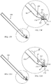
- FIG. 1A-3C illustrate an iris retractor 10, constructed in accordance with a non-limiting embodiment of the present invention.
- Iris retractor 10 includes a plurality of iris grabbing hooks 12 ( Figs. 2A-3C ) disposed or formed at a distal end of one or more slender elements 14.
- the slender elements 14 are arranged to move through a retaining element 16 from a fully retracted position ( Figs. 1A-1C ) to a partially expanded position ( Figs. 2A-2C ) to a fully expanded position ( Figs. 3A-3C ).
- a proximal portion 18 of retaining element 16 is formed with a groove 19.
- the proximal ends of slender elements 14 terminate in a proximal handle 20.
- the slender elements 14 may be joined as a single element before connection to handle 20 or may be joined at the handle 20.
- handle 20 In the fully expanded position, handle 20 is pushed completely into groove 19 and is squeezed and held in this position by the side walls of groove 19. (Alternatively, handle 20 may "click" into groove 19.
- Retaining element 16 retains slender elements 14 in the retracted position until handle 20 is pushed towards groove 19.
- Slender elements 14 and hooks 12 may be constructed of a metal or plastic wire, such as but not limited, NITINOL or stainless steel or a medically safe plastic with suitable resilience, e.g., a shape memory polymer plastic.
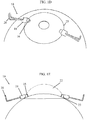
- Figs. 1D-1E illustrate a pair of iris retractors 10 in a non-expanded orientation (i.e., retracted position) placed on an eye.
- a portion of retaining element 16 abuts against the cornea 22, typically but not necessarily at the limbus 23.
- iris retractor 10 is inserted through a small incision (e.g., 1.0-1.5 mm incision) at the limbus 23. Retaining element 16 prevents iris retractor 10 from encroaching too much into the cornea 22.
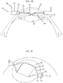
- Pushing handle 20 towards retaining element 16 deploys slender elements 14 and hooks 12 out of retaining element 16. As seen in Figs. 3D-3E , hooks 12 grab and hook onto the iris 24 and retract the iris 24 for exposing the lens 25 to provide a good working opening for the surgeon.
- Retaining element 16 anchors the retractor 10 by applying a counter force on the outside of the limbus 23.
- Hooks 12 are separate and spaced apart from each other upon distal movement of slender elements 14 through retaining element 16.
- a single iris retractor provides spaced apart retraction points, as opposed to some prior art iris retractors which only work at a single point.
- the incision for insertion of the iris retractor may be made at a different position (e.g., perpendicular thereto) than the incision made for phacoemulsification. This is advantageous because in this manner the iris retractor does not get in the way of the surgeon.
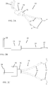
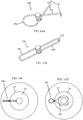
- FIG. 4A-5E illustrate an iris retractor 30, constructed in accordance with another embodiment of the present invention.
- Iris retractor 30 includes a plurality of hooks 32 disposed or formed at a distal end of one or more slender elements 34. In the illustrated embodiment, there are two slender elements 34. The proximal ends of slender elements 34 terminate in a proximal handle 40. Handle 40 and slender elements 34 are made of a resilient, flexible material (e.g., metal or plastic) to form a kind of resilient tweezers or pliers. The slender elements 34 are held in the non-expanded (retracted) orientation by a retaining element 36 (which may be formed as a loop) of the slender elements 34 being caught in one or more proximal grooves 38 formed in the other slender element 34. Another option for keeping iris retractor 30 in its non-expanded state is by pressing elements 37, without slender elements 34 being caught in grooves 38.
- a retaining element 36 which may be formed as a loop
- Figs. 4D-4E illustrate a pair of iris retractors 30 in a non-expanded orientation (i.e., retracted position) placed on the eye.
- a portion of retaining element 36 abuts against the cornea 22, typically but not necessarily at the limbus 23.
- Squeezing handle 40 releases the slender element 34 that is initially caught in groove 38 of retaining element 36.
- iris retractor 30 moves to the expanded position by releasing elements 37.
- slender elements 34 spring outwards to the expanded position in Figs. 5A-5E .
- the geometry of iris retractor 30 enables expansion of hooks 32 without resulting in significant expansion in the area of retaining elements 36.
- hooks 32 grab and hook onto the iris 24 and retract the iris 24 for exposing the lens 25 to provide a good working opening for the surgeon.
- Retaining element 36 anchors the retractor 30 by applying a counter force on the outside of the limbus 23.
- Fig. 5F illustrates a modified version of the iris retractor 30, in accordance with an embodiment of the present invention.
- iris retractor 30 is provided with a flexible clip 42 in handle 40. This design allows making the retractor smaller and may provide more spring (expansion) force.
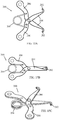
- FIG. 6A-7E illustrate an iris retractor 50, constructed in accordance with yet another embodiment of the present invention.
- Iris retractor 50 includes a plurality of hooks 52 disposed or formed at a distal end of one or more slender elements 54. In the illustrated embodiment, there are two slender elements 54, which pivot about a pivot 56. The proximal ends of slender elements 54 terminate in a proximal handle 60. Handle 60, pivot 56 and slender elements 54 form a kind of scissors. Iris retractor 50 is normally expanded and slender elements 54 are held in the non-expanded (retracted) orientation by the resilience of handle 60 (thus handle 60 serves as the retaining element for initially holding the slender elements 54 in the retracted orientation.
- Figs. 6D-6E illustrate a pair of iris retractors 50 in a non-expanded orientation (i.e., retracted position) placed on the eye.
- a portion of iris retractor 50 e.g., near the pivot 56
- Manipulating handle 60 "scissors out” the slender elements 54 to the expanded position in Figs. 7A-7E .
- hooks 52 grab and hook onto the iris 24 and retract the iris 24 for exposing the lens 25 to provide a good working opening for the surgeon.
- a portion of iris retractor 50 (e.g., near the pivot 56) anchors the retractor 50 by applying a counter force on the outside of the limbus 23.
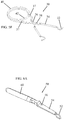
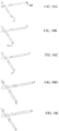
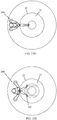
- Figs. 8 and 9 illustrate different tips for the iris retractor of any of the above embodiments, in accordance with different embodiments of the present invention.
- a tip 70 is shown that has a U-shaped hook with a short distal extension 72.
- Fig. 9 the same tip 70 is shown extending from a proximal sleeve 74.
- the sleeved hooks (as shown in Fig. 9 ) can be retracted as shown in Fig. 10 .
- Fig. 9A illustrates the iris retractor with the distal extension 72 of Fig. 8 or 9 in use, in accordance with an embodiment of the present invention. It is seen that distal extension 72 firmly and positively sets the tool against the edges of the iris, and thus helps ensure proper, reliable and safe retraction of the iris.
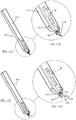
- Figs. 10A-10E illustrate a sleeved hook 80 for the iris retractor of any of the above embodiments, in accordance with an embodiment of the present invention, shown gradually from fully extended to fully retracted positions.
- Sleeved hook 80 is similar to the hook shown on Fig. 9 , and may or may not have a distal extension like the embodiment of Fig. 9 .
- Any suitable retracting mechanism (not shown) may be used to retract and/or extend retractable hook 80 into and/or out of the slender elements.
- FIG. 11 illustrates an iris retractor 150, constructed in accordance with another embodiment of the present invention.
- Iris retractor 150 includes a plurality of hooks 152 disposed or formed at distal ends of a first slender element 154.
- the first slender element 154 may be adjustable in length, such as by means of a flexible and extendable member 155 at a central portion thereof.
- a second slender element 156 (which may be arranged to move through a guide element, not shown, similar to that described above) is pivotally attached to first slender element 154.
- An anchor element 158 is mounted at a proximal position on the second slender element 156. The proximal end of second slender element 156 terminates in a proximal handle 160.
- the hooks 152 and first slender element 154 are inserted through a small incision at the limbus 144 and are manipulated by the surgeon so that hooks 152 spread apart and retract the iris 134.
- Anchor element 158 anchors the retractor by applying a counter force on the outside of limbus 144.
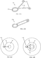
- FIG. 12A-12D illustrate an iris retractor 170, constructed in accordance with another embodiment of the present invention.
- Iris retractor 170 includes a plurality of hooks 172 disposed or formed at a distal end of one or more slender elements 174. In the illustrated embodiment, there are two slender elements 174. The proximal ends of slender elements 174 terminate in a proximal handle 176. Handle 176 and slender elements 174 are made of a resilient, flexible material (e.g., metal or plastic) to form a kind of resilient tweezers or pliers. The hooks 172 in this embodiment curve back onto slender elements 174 and may optionally abut against slender elements 174.
- a resilient, flexible material e.g., metal or plastic
- Fig. 12C illustrates iris retractor 170 in a non-expanded orientation inserted through a small incision at the limbus 23.
- Fig. 12D illustrates iris retractor 170 in an expanded orientation, wherein hooks 172 grab and hook onto the iris 24 and retract the iris 24 for exposing the lens to provide a good working opening for the surgeon.
- FIG. 13A-13H illustrate a manipulator 180, for operating iris retractor 170, constructed in accordance with an embodiment of the present invention.
- Manipulator 180 includes a retaining element 181 pivotally connected to a toggle lever 182, which is in turn pivotally connected at a pivot 183 on a distal end of a handle 184.
- the distal end of a handle 184 includes an anvil 185 formed with a hole 186 through which retaining element 181 passes.
- Handle 176 of iris retractor 170 fits on a lug 187 (e.g., pin) that protrudes from the bottom side of anvil 185. Lug 187 fits into the center of handle 176.
- toggle lever 182 is moved to the position wherein retaining element 181 is moved down to clamp around the slender elements 174 of iris retractor 170, thus retaining slender elements 174 in the non-expanded orientation (retracted position).
- toggle lever 182 is moved to the position (indicated by arrow F) wherein retaining element 181 is moved up to release the slender elements 174 of iris retractor 170, thus allowing slender elements 174 to expand to the expanded orientation.
- FIG. 14A-14D illustrate an iris retractor 190, constructed in accordance with another embodiment of the present invention.
- Iris retractor 190 includes a plurality of hooks 192 disposed or formed at a distal end of one or more slender elements 194. In the illustrated embodiment, there are two slender elements 194. The proximal ends of slender elements 194 terminate in a proximal handle 196.
- Handle 196 and slender elements 194 are made of a resilient, flexible material (e.g., metal or plastic or shape memory) to form a kind of resilient tweezers or pliers.
- Handle 196 in this embodiment is sufficiently resilient such that it flattens into an oblong shape when squeezed, as seen in Fig. 14B . Handle 196 springs back to its original shape to move iris retractor 190 to the expanded orientation.
- Fig. 14C illustrates iris retractor 190 in a non-expanded orientation inserted through a small incision at the limbus 23.
- handle 196 flattens into an oblong shape.
- Fig. 14D illustrates iris retractor 190 in an expanded orientation, wherein hooks 192 grab and hook onto the iris 24 and retract the iris 24 for exposing the lens to provide a good working opening for the surgeon.
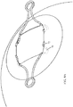
- FIG. 15A-15E illustrate an iris retractor 200, constructed in accordance with another embodiment of the present invention.
- Iris retractor 200 includes a plurality of hooks 202 disposed or formed at a distal end of one or more slender elements 204. In the illustrated embodiment, there are two slender elements 204. The proximal ends of slender elements 204 form a proximal handle that includes two scissor handles 206. Handles 206 are spring loaded by a biasing device 208, such as a coil spring which has ends attached to the handles 206.
- a biasing device 208 such as a coil spring which has ends attached to the handles 206.
- Fig. 15D illustrates iris retractor 200 in a non-expanded orientation inserted through a small incision at the limbus 23. Handles 206 are squeezed and held together so that slender elements 204 are retracted together, as shown in Fig. 15B .
- Fig. 15E illustrates iris retractor 200 in an expanded orientation, wherein hooks 202 grab and hook onto the iris 24 and retract the iris 24 for exposing the lens to provide a good working opening for the surgeon.
Landscapes
- Health & Medical Sciences (AREA)
- Life Sciences & Earth Sciences (AREA)
- Surgery (AREA)
- Ophthalmology & Optometry (AREA)
- Engineering & Computer Science (AREA)
- Biomedical Technology (AREA)
- Heart & Thoracic Surgery (AREA)
- Nuclear Medicine, Radiotherapy & Molecular Imaging (AREA)
- Animal Behavior & Ethology (AREA)
- General Health & Medical Sciences (AREA)
- Public Health (AREA)
- Veterinary Medicine (AREA)
- Medical Informatics (AREA)
- Molecular Biology (AREA)
- Vascular Medicine (AREA)
- Surgical Instruments (AREA)
Description
- The present invention relates generally to an iris retractor used in ophthalmic surgical procedures.
- There are various ophthalmic procedures that require the dilation of the pupil. For example, a lens with a cataract is typically removed from the eye by phacoemulsification. This procedure breaks up the lens typically with an ultrasonically driven tool. The tool has an aspiration port that aspirates the broken lens material from the patient's ocular- chamber. It is desirable to extend the pupil during phacoemulsification to provide the surgeon with a wide view of the lens. One technique for extending the pupil includes pulling back or retracting the iris with what is referred to as an iris retractor, and holding the iris at its outer edges.
-
US-A-5607446 describes an instrument for dilating the pupil of an eye. The instrument includes a handle and a switch mounted on the handle for alternating between first and second states. A retractable dilator mechanism is attached to the switch and is extendible from the handle. The dilator mechanism selectively alternates between a retracted condition when the switch is in a first state and an expanded condition when the switch is in its second state. -
US-A-4257406 describes a instrument for use in ophthalmic surgery to retract the iris and provide dilation of the pupil. The instrument includes a pair of curved retracting tips adapted to engage the iris gently and positively for expanding the pupil to permit removal of the crystalline lens without injury to the iris. The retracting tips are mounted on a pair of cross-action spring arms and the instrument is designed for easy comfortable one-hand operation. -
WO2008/115455 describes a ring that can maintain a pupil in an extended position during an ophthalmic procedure. The ring has a plurality of loops that capture iris tissue. The ring is configured to extend the pupil when iris tissue is inserted into each loop. An ophthalmic procedure such as phacoemulsification can then be performed on the patient. The ring has a center opening that provides a wide view of the ocular chamber during the procedure. - The present invention provides a pair of iris retractors, in accordance with claim 1. Preferred embodiments of the invention are provided in the dependent claims.
- There is thus provided in accordance with the invention a pair of iris retractors, wherein each iris retractor includes a plurality of iris grabbing hooks disposed or formed at a distal end of slender elements, and a proximal handle at a proximal end of the slender elements, wherein the slender elements spring outwards resiliently moving between retracted and expanded positions by manipulation of the slender elements, wherein in the retracted position, the hooks are close to one another and the slender elements are close to one another, and wherein in the expanded position, the hooks are separate and spaced apart from each other and distal portions of the slender elements are separate and spaced apart from each other; and
an anchor or a retaining element that anchors the retractor and applies a counter force by abutting the outside of the cornea or limbus. - In accordance with an embodiment a tip of the slender element extends from a proximal sleeve.
- The present invention will be understood and appreciated more fully from the following detailed description taken in conjunction with the drawings in which:
-
Figs. 1A-1C are simplified perspective, top-view and side-view illustrations, respectively, of an iris retractor, in a non-expanded orientation, constructed in accordance with an embodiment of the present invention; -
Figs. 1D-1E are simplified perspective and side-view illustrations, respectively, of the iris retractor ofFigs. 1A-1C , in the non-expanded orientation placed on an eye; -
Figs. 2A-2C are simplified perspective, side-view and top-view illustrations, respectively, of the iris retractor ofFigs. 1A-1C , in a partially expanded orientation, in accordance with an embodiment of the present invention; -
Figs. 3A-3C are simplified perspective, side-view and top-view illustrations, respectively, of the iris retractor ofFigs. 1A-1C , in a fully expanded orientation, in accordance with an embodiment of the present invention; -
Figs. 3D-3E are simplified side-view and perspective illustrations, respectively, of the iris retractor ofFigs. 1A-1C , in the fully expanded orientation placed on the eye; -
Figs. 4A-4C are simplified perspective, side-view and top-view illustrations, respectively, of an iris retractor, in a non-expanded orientation, constructed in accordance with another embodiment of the present invention; -
Figs. 4D-4E are simplified perspective and side-view illustrations, respectively, of the iris retractor ofFigs. 4A-4C , in the non-expanded orientation placed on an eye; -
Figs. 5A-5C are simplified perspective, top-view and side-view illustrations, respectively, of the iris retractor ofFigs. 4A-4C , in an expanded orientation, in accordance with an embodiment of the present invention; -
Figs. 5D-5E are simplified side-view and perspective illustrations, respectively, of the iris retractor ofFigs. 4A-4C , in the expanded orientation placed on the eye; -
Fig. 5F is a simplified perspective illustration of a modified version of the iris retractor ofFigs. 4A-4C , in accordance with an embodiment of the present invention; -
Figs. 6A-6C are simplified perspective, side-view and top-view illustrations, respectively, of an iris retractor, in a non-expanded orientation, constructed in accordance with yet another embodiment of the present invention; -
Figs. 6D-6E are simplified side-view and perspective illustrations, respectively, of the iris retractor ofFigs. 6A-6C , in the non-expanded orientation placed on an eye; -
Figs. 7A-7C are simplified perspective, top-view and side-view illustrations, respectively, of the iris retractor ofFigs. 6A-6C , in an expanded orientation, in accordance with an embodiment of the present invention; -
Figs. 7D-7E are simplified side-view and perspective illustrations, respectively, of the iris retractor ofFigs. 7A-7C , in the expanded orientation placed on the eye; -
Figs. 8 and 9 are simplified perspective illustrations of different tips for the iris retractor of any of the above embodiments, in accordance with different embodiments of the present invention; -
Fig. 9A is a simplified perspective illustration of the iris retractor with the distal extension ofFig. 8 or 9 in use; -
Figs. 10A-10E are simplified perspective illustrations of a retractable tip for the iris retractor of any of the above embodiments, in accordance with an embodiment of the present invention, shown gradually from fully extended to fully retracted positions; -
Fig. 11 is a simplified pictorial illustration of an iris retractor, constructed in accordance with another embodiment of the present invention; -
Figs. 12A-12D are simplified pictorial illustrations of an iris retractor, constructed in accordance with yet another embodiment of the present invention; -
Figs. 13A-13H are simplified pictorial illustrations of a manipulator for operating the iris retractor ofFigs. 12A-12D , constructed in accordance with an embodiment of the present invention; -
Figs. 14A-14D are simplified pictorial illustrations of an iris retractor, constructed in accordance with still another embodiment of the present invention; and -
Figs. 15A-15E are simplified pictorial illustrations of an iris retractor, constructed in accordance with another embodiment of the present invention. - Reference is now made to
Figs. 1A-3C , which illustrate aniris retractor 10, constructed in accordance with a non-limiting embodiment of the present invention. -
Iris retractor 10 includes a plurality of iris grabbing hooks 12 (Figs. 2A-3C ) disposed or formed at a distal end of one or moreslender elements 14. In the illustrated embodiment, there are twoslender elements 14. Theslender elements 14 are arranged to move through a retainingelement 16 from a fully retracted position (Figs. 1A-1C ) to a partially expanded position (Figs. 2A-2C ) to a fully expanded position (Figs. 3A-3C ). Aproximal portion 18 of retainingelement 16 is formed with agroove 19. The proximal ends ofslender elements 14 terminate in aproximal handle 20. Theslender elements 14 may be joined as a single element before connection to handle 20 or may be joined at thehandle 20. In the fully expanded position, handle 20 is pushed completely intogroove 19 and is squeezed and held in this position by the side walls ofgroove 19. (Alternatively, handle 20 may "click" intogroove 19. Accordingly, there can be a fixed configuration, wherein handle 20 clicks intogroove 19 andslender elements 14 have a fixed expansion, or an adjustable expansion configuration, wherein the more theslender elements 14 are inserted into the eye the larger is their lateral expansion.) Retainingelement 16 retainsslender elements 14 in the retracted position untilhandle 20 is pushed towardsgroove 19. -
Slender elements 14 and hooks 12 may be constructed of a metal or plastic wire, such as but not limited, NITINOL or stainless steel or a medically safe plastic with suitable resilience, e.g., a shape memory polymer plastic. -
Figs. 1D-1E illustrate a pair ofiris retractors 10 in a non-expanded orientation (i.e., retracted position) placed on an eye. A portion of retainingelement 16 abuts against thecornea 22, typically but not necessarily at thelimbus 23. As seen in the figures,iris retractor 10 is inserted through a small incision (e.g., 1.0-1.5 mm incision) at thelimbus 23. Retainingelement 16 preventsiris retractor 10 from encroaching too much into thecornea 22. - Pushing
handle 20 towards retainingelement 16 deploysslender elements 14 and hooks 12 out of retainingelement 16. As seen inFigs. 3D-3E , hooks 12 grab and hook onto theiris 24 and retract theiris 24 for exposing thelens 25 to provide a good working opening for the surgeon. Retainingelement 16 anchors theretractor 10 by applying a counter force on the outside of thelimbus 23. -
Hooks 12 are separate and spaced apart from each other upon distal movement ofslender elements 14 through retainingelement 16. Thus, a single iris retractor provides spaced apart retraction points, as opposed to some prior art iris retractors which only work at a single point. - The incision for insertion of the iris retractor may be made at a different position (e.g., perpendicular thereto) than the incision made for phacoemulsification. This is advantageous because in this manner the iris retractor does not get in the way of the surgeon.
- Reference is now made to
Figs. 4A-5E , which illustrate aniris retractor 30, constructed in accordance with another embodiment of the present invention. -
Iris retractor 30 includes a plurality ofhooks 32 disposed or formed at a distal end of one or moreslender elements 34. In the illustrated embodiment, there are twoslender elements 34. The proximal ends ofslender elements 34 terminate in aproximal handle 40.Handle 40 andslender elements 34 are made of a resilient, flexible material (e.g., metal or plastic) to form a kind of resilient tweezers or pliers. Theslender elements 34 are held in the non-expanded (retracted) orientation by a retaining element 36 (which may be formed as a loop) of theslender elements 34 being caught in one or moreproximal grooves 38 formed in the otherslender element 34. Another option for keepingiris retractor 30 in its non-expanded state is bypressing elements 37, withoutslender elements 34 being caught ingrooves 38. -
Figs. 4D-4E illustrate a pair ofiris retractors 30 in a non-expanded orientation (i.e., retracted position) placed on the eye. A portion of retainingelement 36 abuts against thecornea 22, typically but not necessarily at thelimbus 23. - Squeezing
handle 40 releases theslender element 34 that is initially caught ingroove 38 of retainingelement 36. (For the other option mentioned above,iris retractor 30 moves to the expanded position by releasingelements 37.) By virtue of their resilience,slender elements 34 spring outwards to the expanded position inFigs. 5A-5E . As seen inFigs. 4A-5E , the geometry ofiris retractor 30 enables expansion ofhooks 32 without resulting in significant expansion in the area of retainingelements 36. - As seen in
Figs. 5D-5E , hooks 32 grab and hook onto theiris 24 and retract theiris 24 for exposing thelens 25 to provide a good working opening for the surgeon. Retainingelement 36 anchors theretractor 30 by applying a counter force on the outside of thelimbus 23. - Reference is now made to
Fig. 5F , which illustrates a modified version of theiris retractor 30, in accordance with an embodiment of the present invention. In this embodiment,iris retractor 30 is provided with aflexible clip 42 inhandle 40. This design allows making the retractor smaller and may provide more spring (expansion) force. - Reference is now made to
Figs. 6A-7E , which illustrate aniris retractor 50, constructed in accordance with yet another embodiment of the present invention. -
Iris retractor 50 includes a plurality ofhooks 52 disposed or formed at a distal end of one or moreslender elements 54. In the illustrated embodiment, there are twoslender elements 54, which pivot about apivot 56. The proximal ends ofslender elements 54 terminate in aproximal handle 60.Handle 60,pivot 56 andslender elements 54 form a kind of scissors.Iris retractor 50 is normally expanded andslender elements 54 are held in the non-expanded (retracted) orientation by the resilience of handle 60 (thus handle 60 serves as the retaining element for initially holding theslender elements 54 in the retracted orientation. -
Figs. 6D-6E illustrate a pair ofiris retractors 50 in a non-expanded orientation (i.e., retracted position) placed on the eye. A portion of iris retractor 50 (e.g., near the pivot 56) abuts against thecornea 22, typically but not necessarily at thelimbus 23. - Manipulating
handle 60 "scissors out" theslender elements 54 to the expanded position inFigs. 7A-7E . As seen inFigs. 7D-7E , hooks 52 grab and hook onto theiris 24 and retract theiris 24 for exposing thelens 25 to provide a good working opening for the surgeon. A portion of iris retractor 50 (e.g., near the pivot 56) anchors theretractor 50 by applying a counter force on the outside of thelimbus 23. - Reference is now made to
Figs. 8 and 9 , which illustrate different tips for the iris retractor of any of the above embodiments, in accordance with different embodiments of the present invention. InFig. 8 , atip 70 is shown that has a U-shaped hook with a shortdistal extension 72. InFig. 9 , thesame tip 70 is shown extending from aproximal sleeve 74. The sleeved hooks (as shown inFig. 9 ) can be retracted as shown inFig. 10 . - Reference is now made to
Fig. 9A , which illustrates the iris retractor with thedistal extension 72 ofFig. 8 or 9 in use, in accordance with an embodiment of the present invention. It is seen thatdistal extension 72 firmly and positively sets the tool against the edges of the iris, and thus helps ensure proper, reliable and safe retraction of the iris. - Reference is now made to
Figs. 10A-10E , which illustrate asleeved hook 80 for the iris retractor of any of the above embodiments, in accordance with an embodiment of the present invention, shown gradually from fully extended to fully retracted positions.Sleeved hook 80 is similar to the hook shown onFig. 9 , and may or may not have a distal extension like the embodiment ofFig. 9 . Any suitable retracting mechanism (not shown) may be used to retract and/or extendretractable hook 80 into and/or out of the slender elements. - Reference is now made to
Fig. 11 , which illustrates aniris retractor 150, constructed in accordance with another embodiment of the present invention. -
Iris retractor 150 includes a plurality ofhooks 152 disposed or formed at distal ends of a firstslender element 154. The firstslender element 154 may be adjustable in length, such as by means of a flexible andextendable member 155 at a central portion thereof. A second slender element 156 (which may be arranged to move through a guide element, not shown, similar to that described above) is pivotally attached to firstslender element 154. Ananchor element 158 is mounted at a proximal position on the secondslender element 156. The proximal end of secondslender element 156 terminates in aproximal handle 160. - As seen in
Fig. 11 , thehooks 152 and firstslender element 154 are inserted through a small incision at thelimbus 144 and are manipulated by the surgeon so that hooks 152 spread apart and retract theiris 134.Anchor element 158 anchors the retractor by applying a counter force on the outside oflimbus 144. - Reference is now made to
Figs. 12A-12D , which illustrate aniris retractor 170, constructed in accordance with another embodiment of the present invention. -
Iris retractor 170 includes a plurality ofhooks 172 disposed or formed at a distal end of one or moreslender elements 174. In the illustrated embodiment, there are twoslender elements 174. The proximal ends ofslender elements 174 terminate in aproximal handle 176. Handle 176 andslender elements 174 are made of a resilient, flexible material (e.g., metal or plastic) to form a kind of resilient tweezers or pliers. Thehooks 172 in this embodiment curve back ontoslender elements 174 and may optionally abut againstslender elements 174. -
Fig. 12C illustratesiris retractor 170 in a non-expanded orientation inserted through a small incision at thelimbus 23.Fig. 12D illustratesiris retractor 170 in an expanded orientation, wherein hooks 172 grab and hook onto theiris 24 and retract theiris 24 for exposing the lens to provide a good working opening for the surgeon. - Reference is now made to
Figs. 13A-13H , which illustrate amanipulator 180, for operatingiris retractor 170, constructed in accordance with an embodiment of the present invention. -
Manipulator 180 includes a retainingelement 181 pivotally connected to atoggle lever 182, which is in turn pivotally connected at apivot 183 on a distal end of ahandle 184. The distal end of ahandle 184 includes ananvil 185 formed with ahole 186 through which retainingelement 181 passes. Handle 176 ofiris retractor 170 fits on a lug 187 (e.g., pin) that protrudes from the bottom side ofanvil 185.Lug 187 fits into the center ofhandle 176. - In
Figs. 13A, 13B ,13E and 13F ,toggle lever 182 is moved to the position wherein retainingelement 181 is moved down to clamp around theslender elements 174 ofiris retractor 170, thus retainingslender elements 174 in the non-expanded orientation (retracted position). InFigs. 13C, 13D ,13G and 13H ,toggle lever 182 is moved to the position (indicated by arrow F) wherein retainingelement 181 is moved up to release theslender elements 174 ofiris retractor 170, thus allowingslender elements 174 to expand to the expanded orientation. - Reference is now made to
Figs. 14A-14D , which illustrate aniris retractor 190, constructed in accordance with another embodiment of the present invention. -
Iris retractor 190 includes a plurality ofhooks 192 disposed or formed at a distal end of one or moreslender elements 194. In the illustrated embodiment, there are twoslender elements 194. The proximal ends ofslender elements 194 terminate in aproximal handle 196. Handle 196 andslender elements 194 are made of a resilient, flexible material (e.g., metal or plastic or shape memory) to form a kind of resilient tweezers or pliers. Handle 196 in this embodiment is sufficiently resilient such that it flattens into an oblong shape when squeezed, as seen inFig. 14B . Handle 196 springs back to its original shape to moveiris retractor 190 to the expanded orientation. -
Fig. 14C illustratesiris retractor 190 in a non-expanded orientation inserted through a small incision at thelimbus 23. As mentioned before, handle 196 flattens into an oblong shape.Fig. 14D illustratesiris retractor 190 in an expanded orientation, wherein hooks 192 grab and hook onto theiris 24 and retract theiris 24 for exposing the lens to provide a good working opening for the surgeon. - Reference is now made to
Figs. 15A-15E , which illustrate aniris retractor 200, constructed in accordance with another embodiment of the present invention. -
Iris retractor 200 includes a plurality ofhooks 202 disposed or formed at a distal end of one or moreslender elements 204. In the illustrated embodiment, there are twoslender elements 204. The proximal ends ofslender elements 204 form a proximal handle that includes two scissor handles 206.Handles 206 are spring loaded by abiasing device 208, such as a coil spring which has ends attached to thehandles 206. -
Fig. 15D illustratesiris retractor 200 in a non-expanded orientation inserted through a small incision at thelimbus 23.Handles 206 are squeezed and held together so thatslender elements 204 are retracted together, as shown inFig. 15B .Fig. 15E illustratesiris retractor 200 in an expanded orientation, wherein hooks 202 grab and hook onto theiris 24 and retract theiris 24 for exposing the lens to provide a good working opening for the surgeon.
Claims (5)
- A pair of iris retractors, wherein each iris retractor (10, 30, 50, 150, 170, 190, 200)
comprises:a plurality of iris grabbing hooks (12,32,52,152,172,192,202) disposed or formed at a distal end of slender elements (14, 34, 54, 154, 174, 194, 204); anda proximal handle (20, 40, 60, 176, 196, 206) at a proximal end of said slender elements (14, 34, 54, 154, 174, 194, 204), wherein said slender elements (14, 34, 54, 154, 174, 194, 204) spring outwards resiliently moving between retracted and expanded positions by manipulation of said slender elements (14,34,54,154,174,194,204), wherein in the retracted position, said hooks (12, 32, 52, 152, 172, 192,202) are close to one another and said slender elements (14, 34, 54, 154, 174, 194, 204) are close to one another, and wherein in the expanded position, said hooks (12, 32, 52, 152, 172, 192,202) are separate and spaced apart from each other and distal portions of said slender elements (14, 34, 54, 154, 174, 194, 204) are separate and spaced apart from each other; andan anchor or a retaining element (16, 36, 158) that anchors the retractor and applies a counter force by abutting the outside of the cornea or limbus. - The pair of iris retractors according to claim 1, wherein a tip of said slender element extends from a proximal sleeve (74).
- The pair of iris retractors according to claim 1, wherein said hooks (172) curve back onto said slender elements (174).
- The pair of iris retractors according to claim 1, wherein said handle (196) is sufficiently resilient to flatten into an oblong shape when squeezed.
- The pair of iris retractors according to claim 1, wherein said handle comprises two scissor handles.
Applications Claiming Priority (2)
| Application Number | Priority Date | Filing Date | Title |
|---|---|---|---|
| US25708709P | 2009-11-02 | 2009-11-02 | |
| PCT/US2010/055026 WO2011053945A2 (en) | 2009-11-02 | 2010-11-02 | Iris retractor |
Publications (2)
| Publication Number | Publication Date |
|---|---|
| EP2496145A2 EP2496145A2 (en) | 2012-09-12 |
| EP2496145B1 true EP2496145B1 (en) | 2020-05-13 |
Family
ID=43827152
Family Applications (1)
| Application Number | Title | Priority Date | Filing Date |
|---|---|---|---|
| EP10798648.1A Active EP2496145B1 (en) | 2009-11-02 | 2010-11-02 | Iris retractor |
Country Status (12)
| Country | Link |
|---|---|
| US (1) | US20120232351A1 (en) |
| EP (1) | EP2496145B1 (en) |
| JP (1) | JP5819311B2 (en) |
| KR (1) | KR20130006588A (en) |
| CN (1) | CN102791201B (en) |
| AU (1) | AU2010313159B2 (en) |
| BR (1) | BR112012010391A2 (en) |
| CA (1) | CA2779500A1 (en) |
| ES (1) | ES2809299T3 (en) |
| IL (1) | IL219539A (en) |
| RU (1) | RU2564074C2 (en) |
| WO (1) | WO2011053945A2 (en) |
Families Citing this family (14)
| Publication number | Priority date | Publication date | Assignee | Title |
|---|---|---|---|---|
| US9610072B2 (en) * | 2009-11-02 | 2017-04-04 | Apx Opthalmology Ltd. | Iris retractor |
| WO2012048348A1 (en) * | 2010-10-08 | 2012-04-12 | Prywes Arnold S | Apparatus and method for performing ocular surgery |
| DE102010054333B4 (en) * | 2010-12-13 | 2019-05-29 | Stryker European Holdings I, LLC (n.d. Ges. d. Staates Delaware) | Surgical retractor |
| EP2770939A2 (en) | 2011-10-24 | 2014-09-03 | APX Ophthalmology Ltd. | Iris retractor assemblies |
| RU2485920C1 (en) * | 2012-02-15 | 2013-06-27 | Александр Владимирович Кулик | Method of phacoemulsification of eyes with narrow pupils |
| WO2014132264A1 (en) * | 2013-02-27 | 2014-09-04 | Bhattacharjee Suven | Device providing enlargement & preventing collapse of the pupil of the eye |
| RU2543545C1 (en) * | 2013-10-08 | 2015-03-10 | Государственное бюджетное учреждение "Уфимский научно-исследовательский институт глазных болезней Академии наук Республики Башкортостан" | Method for removing crystalline lens with intraocular lens implantation with narrow rigid pupil |
| WO2016042551A1 (en) * | 2014-09-17 | 2016-03-24 | Apx Ophthalmology Ltd. | Iris retractor |
| RU191333U1 (en) * | 2017-10-19 | 2019-08-01 | федеральное государственное автономное учреждение "Национальный медицинский исследовательский центр "Межотраслевой научно-технический комплекс "Микрохирургия глаза" имени академика С.Н. Федорова" Министерства здравоохранения Российской Федерации | Pupil dilation tool |
| WO2020002719A1 (en) * | 2018-06-27 | 2020-01-02 | Palomino Munoz Antonio | Pupil dilator for ophthalmological operations |
| RU189020U1 (en) * | 2018-12-17 | 2019-05-06 | Акционерное общество "Екатеринбургский центр МНТК "Микрохирургия глаза" | IRIDO-CAPSULAR RETRACTOR MODIFIED |
| KR102339575B1 (en) * | 2019-10-23 | 2021-12-16 | 주식회사 엔도비전 | Spine Retractor |
| RU206049U1 (en) * | 2021-02-04 | 2021-08-17 | Федеральное государственное бюджетное научное учреждение "Российский научный центр хирургии имени академика Б.В. Петровского" | Papillary muscle retractor hook |
| CN113456133B (en) * | 2021-07-28 | 2022-11-29 | 熊义斌 | Eyelid retractor |
Family Cites Families (28)
| Publication number | Priority date | Publication date | Assignee | Title |
|---|---|---|---|---|
| US2234715A (en) * | 1939-09-16 | 1941-03-11 | Carl H Whitney | Mortician's instrument |
| US3742560A (en) * | 1971-12-30 | 1973-07-03 | J Kessler | Clamping apparatus |
| US3916907A (en) * | 1974-06-21 | 1975-11-04 | Wendell C Peterson | Spreader instrument for use in performing a spinal fusion |
| US4257406A (en) * | 1979-05-18 | 1981-03-24 | Schenk Alan G | Iris retractor and pupil dilator |
| SU944558A1 (en) * | 1980-06-25 | 1982-07-23 | Иркутский Государственный Медицинский Институт | Pupil dilator |
| JPS61209647A (en) * | 1985-03-14 | 1986-09-17 | 須广 久善 | Incision opening retractor for connecting blood vessel |
| US5176129A (en) * | 1991-03-01 | 1993-01-05 | Tekdyne, Inc. | Self-retaining refractor |
| US5607446A (en) * | 1995-01-31 | 1997-03-04 | Beehler; Cecil C. | Pupil dilator |
| DE19538951C2 (en) * | 1995-10-19 | 1998-04-30 | Detlef H Dr Holzwig | Device for spreading an eye iris |
| AU2666097A (en) * | 1996-04-10 | 1997-10-29 | Endoscopic Technologies, Inc. | Improving visualization during closed-chest surgery |
| US6309349B1 (en) * | 1996-04-10 | 2001-10-30 | Endoscopic Technologies, Inc. | Surgical retractor and stabilizing device and method for use |
| US5807244A (en) * | 1996-11-15 | 1998-09-15 | Barot; Jagdish Shantilal | Single use disposable iris retractor |
| US6299617B1 (en) * | 1998-03-30 | 2001-10-09 | John Stamler | Instrument for fixating the eye during cataract surgery |
| DE69940641D1 (en) * | 1998-10-02 | 2009-05-07 | Synthes Gmbh | Ffe |
| EP1029508A1 (en) * | 1999-02-19 | 2000-08-23 | Gerrit Reinold Jacob Melles | Ocular speculum and method for separation of eyelids |
| US6561974B1 (en) * | 2000-05-31 | 2003-05-13 | Grieshaber & Co. Ag Schaffhausen | Device for use in a surgical procedure on an eye of a living being, and method of retracting the iris |
| US6663562B2 (en) * | 2001-09-14 | 2003-12-16 | David Chang | Surgical retractor |
| US20030055320A1 (en) * | 2001-09-18 | 2003-03-20 | Mcbride G. Grady | Tissue retractor |
| US20050215864A1 (en) * | 2004-03-24 | 2005-09-29 | Su-Yeon Jang | Retracting and dissecting apparatus for surgical operation, and minimal incision penile augmentation using the same |
| CA2597944A1 (en) * | 2004-08-15 | 2006-02-23 | Kevin Seex | Distraction and retraction assemblies |
| US20110060194A1 (en) * | 2004-12-29 | 2011-03-10 | Olof Risto | Retractor |
| SE0403211L (en) * | 2004-12-29 | 2005-11-15 | Olof Risto | Resilient wound hook of X-ray permeable material to keep wounds open during surgical procedure |
| WO2007068128A1 (en) * | 2005-12-15 | 2007-06-21 | Synthes Gmbh | A pair of tongs apt for soft tissue spreading |
| US20070299315A1 (en) * | 2006-06-21 | 2007-12-27 | Geller Peter L | Novel retractor for hernia surgery |
| US8142355B2 (en) * | 2006-09-25 | 2012-03-27 | Spinal Elements, Inc. | Surgical tissue retractor |
| US8323296B2 (en) * | 2007-03-15 | 2012-12-04 | Boris Malyugin | Ring used in a small pupil phacoemulsification procedure |
| PL2192861T3 (en) * | 2007-08-10 | 2015-10-30 | Girius Antanaitis | Surgical retractor |
| US9095322B2 (en) * | 2011-09-21 | 2015-08-04 | Beaver-Visitec International (Us), Inc. | Speculum with hinged portion |
-
2010
- 2010-11-02 KR KR1020127013396A patent/KR20130006588A/en not_active Application Discontinuation
- 2010-11-02 AU AU2010313159A patent/AU2010313159B2/en not_active Ceased
- 2010-11-02 EP EP10798648.1A patent/EP2496145B1/en active Active
- 2010-11-02 ES ES10798648T patent/ES2809299T3/en active Active
- 2010-11-02 CA CA2779500A patent/CA2779500A1/en not_active Abandoned
- 2010-11-02 JP JP2012537181A patent/JP5819311B2/en active Active
- 2010-11-02 RU RU2012122328/14A patent/RU2564074C2/en active
- 2010-11-02 BR BR112012010391A patent/BR112012010391A2/en not_active IP Right Cessation
- 2010-11-02 US US13/505,510 patent/US20120232351A1/en not_active Abandoned
- 2010-11-02 WO PCT/US2010/055026 patent/WO2011053945A2/en active Application Filing
- 2010-11-02 CN CN201080058298.1A patent/CN102791201B/en active Active
-
2012
- 2012-05-02 IL IL219539A patent/IL219539A/en active IP Right Grant
Non-Patent Citations (1)
| Title |
|---|
| None * |
Also Published As
| Publication number | Publication date |
|---|---|
| WO2011053945A3 (en) | 2011-06-23 |
| US20120232351A1 (en) | 2012-09-13 |
| AU2010313159A1 (en) | 2012-05-31 |
| ES2809299T3 (en) | 2021-03-03 |
| CN102791201B (en) | 2016-04-27 |
| RU2012122328A (en) | 2013-12-10 |
| RU2564074C2 (en) | 2015-09-27 |
| WO2011053945A2 (en) | 2011-05-05 |
| KR20130006588A (en) | 2013-01-17 |
| IL219539A0 (en) | 2012-06-28 |
| IL219539A (en) | 2015-09-24 |
| BR112012010391A2 (en) | 2016-07-12 |
| CA2779500A1 (en) | 2011-05-05 |
| JP2013509275A (en) | 2013-03-14 |
| EP2496145A2 (en) | 2012-09-12 |
| JP5819311B2 (en) | 2015-11-24 |
| AU2010313159B2 (en) | 2016-01-21 |
| CN102791201A (en) | 2012-11-21 |
Similar Documents
| Publication | Publication Date | Title |
|---|---|---|
| EP2496145B1 (en) | Iris retractor | |
| US9788824B2 (en) | Iris retraction method | |
| US12115104B2 (en) | Devices and methods for ocular surgery | |
| ES2241527T3 (en) | MATERIAL HANDLING DEVICE. | |
| US6379370B1 (en) | Incising apparatus for use in cataract surgery | |
| US6551326B1 (en) | Capsulorrhexis device | |
| EP2768423B1 (en) | Ophthalmic structure | |
| US7731728B2 (en) | Internal limiting membrane rake | |
| JP2017529213A (en) | Devices and methods for lenticular tissue removal | |
| AU2018243953A1 (en) | Devices and methods for tissue retraction | |
| KR20130031403A (en) | Structure of effector of surgical instrument | |
| US20160262931A1 (en) | Microsurgical forceps with wide jaws | |
| JP2022544973A (en) | capsular retractor | |
| EP3346930B1 (en) | Tenaculum | |
| WO2016042551A1 (en) | Iris retractor | |
| JPWO2020039514A1 (en) | Clip unit and mucosal lifting system | |
| US20140288380A1 (en) | Iris retractor assemblies | |
| CN209933162U (en) | Intraocular forceps cutting device | |
| JPS6121052Y2 (en) | ||
| RU2141296C1 (en) | Device for performance of paracentesis |
Legal Events
| Date | Code | Title | Description |
|---|---|---|---|
| PUAI | Public reference made under article 153(3) epc to a published international application that has entered the european phase |
Free format text: ORIGINAL CODE: 0009012 |
|
| 17P | Request for examination filed |
Effective date: 20120509 |
|
| AK | Designated contracting states |
Kind code of ref document: A2 Designated state(s): AL AT BE BG CH CY CZ DE DK EE ES FI FR GB GR HR HU IE IS IT LI LT LU LV MC MK MT NL NO PL PT RO RS SE SI SK SM TR |
|
| DAX | Request for extension of the european patent (deleted) | ||
| 17Q | First examination report despatched |
Effective date: 20160322 |
|
| STAA | Information on the status of an ep patent application or granted ep patent |
Free format text: STATUS: EXAMINATION IS IN PROGRESS |
|
| GRAP | Despatch of communication of intention to grant a patent |
Free format text: ORIGINAL CODE: EPIDOSNIGR1 |
|
| STAA | Information on the status of an ep patent application or granted ep patent |
Free format text: STATUS: GRANT OF PATENT IS INTENDED |
|
| RIC1 | Information provided on ipc code assigned before grant |
Ipc: A61B 17/02 20060101AFI20191114BHEP Ipc: A61B 17/00 20060101ALN20191114BHEP |
|
| INTG | Intention to grant announced |
Effective date: 20191202 |
|
| GRAS | Grant fee paid |
Free format text: ORIGINAL CODE: EPIDOSNIGR3 |
|
| GRAA | (expected) grant |
Free format text: ORIGINAL CODE: 0009210 |
|
| STAA | Information on the status of an ep patent application or granted ep patent |
Free format text: STATUS: THE PATENT HAS BEEN GRANTED |
|
| AK | Designated contracting states |
Kind code of ref document: B1 Designated state(s): AL AT BE BG CH CY CZ DE DK EE ES FI FR GB GR HR HU IE IS IT LI LT LU LV MC MK MT NL NO PL PT RO RS SE SI SK SM TR |
|
| REG | Reference to a national code |
Ref country code: GB Ref legal event code: FG4D |
|
| REG | Reference to a national code |
Ref country code: CH Ref legal event code: EP |
|
| REG | Reference to a national code |
Ref country code: DE Ref legal event code: R096 Ref document number: 602010064344 Country of ref document: DE |
|
| REG | Reference to a national code |
Ref country code: AT Ref legal event code: REF Ref document number: 1269178 Country of ref document: AT Kind code of ref document: T Effective date: 20200615 |
|
| REG | Reference to a national code |
Ref country code: LT Ref legal event code: MG4D |
|
| REG | Reference to a national code |
Ref country code: NL Ref legal event code: MP Effective date: 20200513 |
|
| PG25 | Lapsed in a contracting state [announced via postgrant information from national office to epo] |
Ref country code: PT Free format text: LAPSE BECAUSE OF FAILURE TO SUBMIT A TRANSLATION OF THE DESCRIPTION OR TO PAY THE FEE WITHIN THE PRESCRIBED TIME-LIMIT Effective date: 20200914 Ref country code: IS Free format text: LAPSE BECAUSE OF FAILURE TO SUBMIT A TRANSLATION OF THE DESCRIPTION OR TO PAY THE FEE WITHIN THE PRESCRIBED TIME-LIMIT Effective date: 20200913 Ref country code: FI Free format text: LAPSE BECAUSE OF FAILURE TO SUBMIT A TRANSLATION OF THE DESCRIPTION OR TO PAY THE FEE WITHIN THE PRESCRIBED TIME-LIMIT Effective date: 20200513 Ref country code: SE Free format text: LAPSE BECAUSE OF FAILURE TO SUBMIT A TRANSLATION OF THE DESCRIPTION OR TO PAY THE FEE WITHIN THE PRESCRIBED TIME-LIMIT Effective date: 20200513 Ref country code: LT Free format text: LAPSE BECAUSE OF FAILURE TO SUBMIT A TRANSLATION OF THE DESCRIPTION OR TO PAY THE FEE WITHIN THE PRESCRIBED TIME-LIMIT Effective date: 20200513 Ref country code: NO Free format text: LAPSE BECAUSE OF FAILURE TO SUBMIT A TRANSLATION OF THE DESCRIPTION OR TO PAY THE FEE WITHIN THE PRESCRIBED TIME-LIMIT Effective date: 20200813 Ref country code: GR Free format text: LAPSE BECAUSE OF FAILURE TO SUBMIT A TRANSLATION OF THE DESCRIPTION OR TO PAY THE FEE WITHIN THE PRESCRIBED TIME-LIMIT Effective date: 20200814 |
|
| PG25 | Lapsed in a contracting state [announced via postgrant information from national office to epo] |
Ref country code: BG Free format text: LAPSE BECAUSE OF FAILURE TO SUBMIT A TRANSLATION OF THE DESCRIPTION OR TO PAY THE FEE WITHIN THE PRESCRIBED TIME-LIMIT Effective date: 20200813 Ref country code: RS Free format text: LAPSE BECAUSE OF FAILURE TO SUBMIT A TRANSLATION OF THE DESCRIPTION OR TO PAY THE FEE WITHIN THE PRESCRIBED TIME-LIMIT Effective date: 20200513 Ref country code: HR Free format text: LAPSE BECAUSE OF FAILURE TO SUBMIT A TRANSLATION OF THE DESCRIPTION OR TO PAY THE FEE WITHIN THE PRESCRIBED TIME-LIMIT Effective date: 20200513 Ref country code: LV Free format text: LAPSE BECAUSE OF FAILURE TO SUBMIT A TRANSLATION OF THE DESCRIPTION OR TO PAY THE FEE WITHIN THE PRESCRIBED TIME-LIMIT Effective date: 20200513 |
|
| REG | Reference to a national code |
Ref country code: AT Ref legal event code: MK05 Ref document number: 1269178 Country of ref document: AT Kind code of ref document: T Effective date: 20200513 |
|
| PG25 | Lapsed in a contracting state [announced via postgrant information from national office to epo] |
Ref country code: AL Free format text: LAPSE BECAUSE OF FAILURE TO SUBMIT A TRANSLATION OF THE DESCRIPTION OR TO PAY THE FEE WITHIN THE PRESCRIBED TIME-LIMIT Effective date: 20200513 Ref country code: NL Free format text: LAPSE BECAUSE OF FAILURE TO SUBMIT A TRANSLATION OF THE DESCRIPTION OR TO PAY THE FEE WITHIN THE PRESCRIBED TIME-LIMIT Effective date: 20200513 |
|
| PG25 | Lapsed in a contracting state [announced via postgrant information from national office to epo] |
Ref country code: AT Free format text: LAPSE BECAUSE OF FAILURE TO SUBMIT A TRANSLATION OF THE DESCRIPTION OR TO PAY THE FEE WITHIN THE PRESCRIBED TIME-LIMIT Effective date: 20200513 Ref country code: DK Free format text: LAPSE BECAUSE OF FAILURE TO SUBMIT A TRANSLATION OF THE DESCRIPTION OR TO PAY THE FEE WITHIN THE PRESCRIBED TIME-LIMIT Effective date: 20200513 Ref country code: SM Free format text: LAPSE BECAUSE OF FAILURE TO SUBMIT A TRANSLATION OF THE DESCRIPTION OR TO PAY THE FEE WITHIN THE PRESCRIBED TIME-LIMIT Effective date: 20200513 Ref country code: EE Free format text: LAPSE BECAUSE OF FAILURE TO SUBMIT A TRANSLATION OF THE DESCRIPTION OR TO PAY THE FEE WITHIN THE PRESCRIBED TIME-LIMIT Effective date: 20200513 Ref country code: CZ Free format text: LAPSE BECAUSE OF FAILURE TO SUBMIT A TRANSLATION OF THE DESCRIPTION OR TO PAY THE FEE WITHIN THE PRESCRIBED TIME-LIMIT Effective date: 20200513 Ref country code: RO Free format text: LAPSE BECAUSE OF FAILURE TO SUBMIT A TRANSLATION OF THE DESCRIPTION OR TO PAY THE FEE WITHIN THE PRESCRIBED TIME-LIMIT Effective date: 20200513 |
|
| REG | Reference to a national code |
Ref country code: DE Ref legal event code: R097 Ref document number: 602010064344 Country of ref document: DE |
|
| PG25 | Lapsed in a contracting state [announced via postgrant information from national office to epo] |
Ref country code: SK Free format text: LAPSE BECAUSE OF FAILURE TO SUBMIT A TRANSLATION OF THE DESCRIPTION OR TO PAY THE FEE WITHIN THE PRESCRIBED TIME-LIMIT Effective date: 20200513 Ref country code: PL Free format text: LAPSE BECAUSE OF FAILURE TO SUBMIT A TRANSLATION OF THE DESCRIPTION OR TO PAY THE FEE WITHIN THE PRESCRIBED TIME-LIMIT Effective date: 20200513 |
|
| REG | Reference to a national code |
Ref country code: ES Ref legal event code: FG2A Ref document number: 2809299 Country of ref document: ES Kind code of ref document: T3 Effective date: 20210303 |
|
| PLBE | No opposition filed within time limit |
Free format text: ORIGINAL CODE: 0009261 |
|
| STAA | Information on the status of an ep patent application or granted ep patent |
Free format text: STATUS: NO OPPOSITION FILED WITHIN TIME LIMIT |
|
| 26N | No opposition filed |
Effective date: 20210216 |
|
| PG25 | Lapsed in a contracting state [announced via postgrant information from national office to epo] |
Ref country code: SI Free format text: LAPSE BECAUSE OF FAILURE TO SUBMIT A TRANSLATION OF THE DESCRIPTION OR TO PAY THE FEE WITHIN THE PRESCRIBED TIME-LIMIT Effective date: 20200513 |
|
| PG25 | Lapsed in a contracting state [announced via postgrant information from national office to epo] |
Ref country code: MC Free format text: LAPSE BECAUSE OF FAILURE TO SUBMIT A TRANSLATION OF THE DESCRIPTION OR TO PAY THE FEE WITHIN THE PRESCRIBED TIME-LIMIT Effective date: 20200513 |
|
| REG | Reference to a national code |
Ref country code: CH Ref legal event code: PL |
|
| PG25 | Lapsed in a contracting state [announced via postgrant information from national office to epo] |
Ref country code: LU Free format text: LAPSE BECAUSE OF NON-PAYMENT OF DUE FEES Effective date: 20201102 |
|
| REG | Reference to a national code |
Ref country code: BE Ref legal event code: MM Effective date: 20201130 |
|
| PG25 | Lapsed in a contracting state [announced via postgrant information from national office to epo] |
Ref country code: LI Free format text: LAPSE BECAUSE OF NON-PAYMENT OF DUE FEES Effective date: 20201130 Ref country code: CH Free format text: LAPSE BECAUSE OF NON-PAYMENT OF DUE FEES Effective date: 20201130 |
|
| PG25 | Lapsed in a contracting state [announced via postgrant information from national office to epo] |
Ref country code: IE Free format text: LAPSE BECAUSE OF NON-PAYMENT OF DUE FEES Effective date: 20201102 |
|
| PGFP | Annual fee paid to national office [announced via postgrant information from national office to epo] |
Ref country code: ES Payment date: 20211207 Year of fee payment: 12 |
|
| PG25 | Lapsed in a contracting state [announced via postgrant information from national office to epo] |
Ref country code: TR Free format text: LAPSE BECAUSE OF FAILURE TO SUBMIT A TRANSLATION OF THE DESCRIPTION OR TO PAY THE FEE WITHIN THE PRESCRIBED TIME-LIMIT Effective date: 20200513 Ref country code: MT Free format text: LAPSE BECAUSE OF FAILURE TO SUBMIT A TRANSLATION OF THE DESCRIPTION OR TO PAY THE FEE WITHIN THE PRESCRIBED TIME-LIMIT Effective date: 20200513 Ref country code: CY Free format text: LAPSE BECAUSE OF FAILURE TO SUBMIT A TRANSLATION OF THE DESCRIPTION OR TO PAY THE FEE WITHIN THE PRESCRIBED TIME-LIMIT Effective date: 20200513 |
|
| PG25 | Lapsed in a contracting state [announced via postgrant information from national office to epo] |
Ref country code: MK Free format text: LAPSE BECAUSE OF FAILURE TO SUBMIT A TRANSLATION OF THE DESCRIPTION OR TO PAY THE FEE WITHIN THE PRESCRIBED TIME-LIMIT Effective date: 20200513 |
|
| PG25 | Lapsed in a contracting state [announced via postgrant information from national office to epo] |
Ref country code: BE Free format text: LAPSE BECAUSE OF NON-PAYMENT OF DUE FEES Effective date: 20201130 |
|
| PGFP | Annual fee paid to national office [announced via postgrant information from national office to epo] |
Ref country code: IT Payment date: 20230831 Year of fee payment: 14 Ref country code: GB Payment date: 20230903 Year of fee payment: 14 |
|
| PGFP | Annual fee paid to national office [announced via postgrant information from national office to epo] |
Ref country code: FR Payment date: 20230830 Year of fee payment: 14 |
|
| REG | Reference to a national code |
Ref country code: ES Ref legal event code: FD2A Effective date: 20231227 |
|
| PG25 | Lapsed in a contracting state [announced via postgrant information from national office to epo] |
Ref country code: ES Free format text: LAPSE BECAUSE OF NON-PAYMENT OF DUE FEES Effective date: 20221103 |
|
| PG25 | Lapsed in a contracting state [announced via postgrant information from national office to epo] |
Ref country code: ES Free format text: LAPSE BECAUSE OF NON-PAYMENT OF DUE FEES Effective date: 20221103 |
|
| PGFP | Annual fee paid to national office [announced via postgrant information from national office to epo] |
Ref country code: DE Payment date: 20230831 Year of fee payment: 14 |