EP2495790A1 - Solid oxide fuel cell - Google Patents
Solid oxide fuel cell Download PDFInfo
- Publication number
- EP2495790A1 EP2495790A1 EP12157871A EP12157871A EP2495790A1 EP 2495790 A1 EP2495790 A1 EP 2495790A1 EP 12157871 A EP12157871 A EP 12157871A EP 12157871 A EP12157871 A EP 12157871A EP 2495790 A1 EP2495790 A1 EP 2495790A1
- Authority
- EP
- European Patent Office
- Prior art keywords
- reaction prevention
- prevention film
- film
- air electrode
- pores
- Prior art date
- Legal status (The legal status is an assumption and is not a legal conclusion. Google has not performed a legal analysis and makes no representation as to the accuracy of the status listed.)
- Granted
Links
Images
Classifications
-
- H—ELECTRICITY
- H01—ELECTRIC ELEMENTS
- H01M—PROCESSES OR MEANS, e.g. BATTERIES, FOR THE DIRECT CONVERSION OF CHEMICAL ENERGY INTO ELECTRICAL ENERGY
- H01M4/00—Electrodes
- H01M4/86—Inert electrodes with catalytic activity, e.g. for fuel cells
- H01M4/8647—Inert electrodes with catalytic activity, e.g. for fuel cells consisting of more than one material, e.g. consisting of composites
- H01M4/8657—Inert electrodes with catalytic activity, e.g. for fuel cells consisting of more than one material, e.g. consisting of composites layered
-
- H—ELECTRICITY
- H01—ELECTRIC ELEMENTS
- H01M—PROCESSES OR MEANS, e.g. BATTERIES, FOR THE DIRECT CONVERSION OF CHEMICAL ENERGY INTO ELECTRICAL ENERGY
- H01M4/00—Electrodes
- H01M4/86—Inert electrodes with catalytic activity, e.g. for fuel cells
- H01M4/88—Processes of manufacture
- H01M4/8878—Treatment steps after deposition of the catalytic active composition or after shaping of the electrode being free-standing body
- H01M4/8882—Heat treatment, e.g. drying, baking
- H01M4/8885—Sintering or firing
-
- H—ELECTRICITY
- H01—ELECTRIC ELEMENTS
- H01M—PROCESSES OR MEANS, e.g. BATTERIES, FOR THE DIRECT CONVERSION OF CHEMICAL ENERGY INTO ELECTRICAL ENERGY
- H01M4/00—Electrodes
- H01M4/86—Inert electrodes with catalytic activity, e.g. for fuel cells
- H01M4/90—Selection of catalytic material
- H01M4/9016—Oxides, hydroxides or oxygenated metallic salts
-
- H—ELECTRICITY
- H01—ELECTRIC ELEMENTS
- H01M—PROCESSES OR MEANS, e.g. BATTERIES, FOR THE DIRECT CONVERSION OF CHEMICAL ENERGY INTO ELECTRICAL ENERGY
- H01M8/00—Fuel cells; Manufacture thereof
- H01M8/10—Fuel cells with solid electrolytes
- H01M8/12—Fuel cells with solid electrolytes operating at high temperature, e.g. with stabilised ZrO2 electrolyte
- H01M8/1213—Fuel cells with solid electrolytes operating at high temperature, e.g. with stabilised ZrO2 electrolyte characterised by the electrode/electrolyte combination or the supporting material
-
- H—ELECTRICITY
- H01—ELECTRIC ELEMENTS
- H01M—PROCESSES OR MEANS, e.g. BATTERIES, FOR THE DIRECT CONVERSION OF CHEMICAL ENERGY INTO ELECTRICAL ENERGY
- H01M8/00—Fuel cells; Manufacture thereof
- H01M8/10—Fuel cells with solid electrolytes
- H01M8/12—Fuel cells with solid electrolytes operating at high temperature, e.g. with stabilised ZrO2 electrolyte
- H01M8/124—Fuel cells with solid electrolytes operating at high temperature, e.g. with stabilised ZrO2 electrolyte characterised by the process of manufacturing or by the material of the electrolyte
- H01M8/1246—Fuel cells with solid electrolytes operating at high temperature, e.g. with stabilised ZrO2 electrolyte characterised by the process of manufacturing or by the material of the electrolyte the electrolyte consisting of oxides
- H01M8/1253—Fuel cells with solid electrolytes operating at high temperature, e.g. with stabilised ZrO2 electrolyte characterised by the process of manufacturing or by the material of the electrolyte the electrolyte consisting of oxides the electrolyte containing zirconium oxide
-
- Y—GENERAL TAGGING OF NEW TECHNOLOGICAL DEVELOPMENTS; GENERAL TAGGING OF CROSS-SECTIONAL TECHNOLOGIES SPANNING OVER SEVERAL SECTIONS OF THE IPC; TECHNICAL SUBJECTS COVERED BY FORMER USPC CROSS-REFERENCE ART COLLECTIONS [XRACs] AND DIGESTS
- Y02—TECHNOLOGIES OR APPLICATIONS FOR MITIGATION OR ADAPTATION AGAINST CLIMATE CHANGE
- Y02E—REDUCTION OF GREENHOUSE GAS [GHG] EMISSIONS, RELATED TO ENERGY GENERATION, TRANSMISSION OR DISTRIBUTION
- Y02E60/00—Enabling technologies; Technologies with a potential or indirect contribution to GHG emissions mitigation
- Y02E60/30—Hydrogen technology
- Y02E60/50—Fuel cells
-
- Y—GENERAL TAGGING OF NEW TECHNOLOGICAL DEVELOPMENTS; GENERAL TAGGING OF CROSS-SECTIONAL TECHNOLOGIES SPANNING OVER SEVERAL SECTIONS OF THE IPC; TECHNICAL SUBJECTS COVERED BY FORMER USPC CROSS-REFERENCE ART COLLECTIONS [XRACs] AND DIGESTS
- Y02—TECHNOLOGIES OR APPLICATIONS FOR MITIGATION OR ADAPTATION AGAINST CLIMATE CHANGE
- Y02P—CLIMATE CHANGE MITIGATION TECHNOLOGIES IN THE PRODUCTION OR PROCESSING OF GOODS
- Y02P70/00—Climate change mitigation technologies in the production process for final industrial or consumer products
- Y02P70/50—Manufacturing or production processes characterised by the final manufactured product
Definitions
- the present invention relates to a solid oxide fuel cell (SOFC).
- SOFC solid oxide fuel cell
- An SOFC includes a fuel electrode for allowing a fuel gas to be reacted, an air electrode for allowing a gas containing oxygen to be reacted, and a solid electrolyte film provided between the fuel electrode and the air electrode (see, for example, Japanese Patent Application Laid-open No. 2010-3478 ).
- a fuel gas e.g., hydrogen gas
- a gas containing oxygen e.g., air
- chemical reactions represented by the following formulae (1) and (2) occur. Through the chemical reactions, a difference in electric potential is generated between the fuel electrode and the air electrode.
- the difference in electric potential is originated from oxygen conductivity of a solid electrolyte. (1/2) ⁇ O 2 +2 e- ⁇ O 2- (at air electrode) ... (1) H 2 +O 2- ⁇ H 2 O+2 e- (at fuel electrode) ... (2)
- a high-resistance layer (La 2 Zr 2 O 7 ) is liable to be formed through a reaction of lanthanum (La) in LSCF and zirconium (Zr) in YSZ.
- Formation of the high-resistance layer may be one of the causes for increasing interfacial resistance between the air electrode and the solid electrolyte film to decrease an output of the SOFC. Therefore, it is preferred to suppress the formation of the high-resistance layer.
- a porous reaction prevention film including ceria e.g., gadolinium-doped ceria (GDC)
- GDC gadolinium-doped ceria
- An object of the present invention is to provide an SOFC in which a decrease in output of the SOFC due to an increase in electric resistance between an air electrode and a solid electrolyte film hardly occurs after long-term use.
- An SOFC according to the present invention includes: a fuel electrode for allowing a fuel gas to be reacted; an air electrode for allowing a gas containing oxygen to be reacted; a solid electrolyte film provided between the fuel electrode and the air electrode; and a reaction prevention film provided between the air electrode and the solid electrolyte film.
- the reaction prevention film may include cerium.
- the solid electrolyte film may include zirconium.
- the air electrode may include a perovskite-type oxide including at least one of strontium and lanthanum.
- the reaction prevention film has a porosity of less than 10%, and the reaction prevention film includes pores each containing the component for the air electrode.
- the reaction prevention film more preferably has a porosity of 7% or less. It is preferable that the reaction prevention film includes the pores uniformly scattered therein.
- the plural pores existing in the reaction prevention film may consist of only open pores, only closed pores, or both open pores and closed pores.
- the reaction prevention film, that is provided between the air electrode and the solid electrolyte film is configured to consist of more than two layers, the layers must include one or more layers that have a porosity of less than 10 % and include pores each containing the component for the air electrode.
- the reaction prevention film and the solid electrolyte film are suitably formed by simultaneous sintering.
- the porosity of the reaction prevention film is as relatively small as less than 10% (preferably 7% or less)
- the "component for the air electrode” e.g., Sr
- the porosity of the reaction prevention film is 10 to 80%
- the high-resistance layer is unlikely to be formed through a reaction of the "component for the air electrode” (e.g., Sr) and the “component for the solid electrolyte film” (e.g., Zr) in the vicinity of the interface (the details are described later).
- the reaction prevention film suitably includes closed pores each having a diameter of 0.1 to 3 ⁇ m. Moreover, the reaction prevention film suitably has a thickness of 0.5 to 25 ⁇ m.
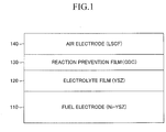
- FIG. 1 is a schematic view illustrating the configuration of an SOFC according to an embodiment of the present invention.
- the SOFC is a laminate including a fuel electrode 110, an electrolyte film 120 laminated on the fuel electrode 110, a reaction prevention film 130 laminated on the electrolyte film 120, and an air electrode 140 laminated on the reaction prevention film 130.
- the cell has a square shape with a side length of 1 to 30 cm, a rectangular shape with a long side length of 5 to 30 cm and a short side length of 3 to 15 cm, or a circular shape with a diameter of 1 to 30 cm.
- the thickness of the cell is 0.1 to 3 mm.
- the fuel electrode 110 is, for example, a porous thin-plate-like sintered body including nickel oxide (NiO) and yttria-stabilized zirconia (YSZ).
- the fuel electrode 110 may include nickel oxide (NiO) and yttria (Y 2 O 3 ).
- the fuel electrode 110 has a thickness of 0.1 to 3 mm. The thickness of the fuel electrode 110 is the largest among the thicknesses of components for the cell, and thus, the fuel electrode 110 functions as a support substrate for the cell.
- the fuel electrode 110 is subjected to a well-known reduction treatment (e.g., treatment for reducing NiO to Ni), resulting in exhibiting conductivity.
- the SOFC operates in a state in which the fuel electrode 110 exhibits conductivity as described above.
- the fuel electrode 110 may include two layers including: a fuel-electrode active portion, which is brought into contact with the electrolyte film 120; and a fuel-electrode current-collecting portion, which corresponds to the residual portion of the fuel electrode except the fuel-electrode active portion.
- the fuel-electrode active portion may include nickel oxide (NiO) and yttria-stabilized zirconia (YSZ).
- the fuel-electrode active portion may include nickel oxide (NiO) and gadolinium-doped ceria (GDC).
- the fuel-electrode current-collecting portion may include nickel oxide (NiO) and yttria-stabilized zirconia (YSZ), for example.
- the fuel-electrode current-collecting portion may include nickel oxide (NiO) and yttria (Y 2 O 3 ).
- the fuel-electrode current-collecting portion includes a substance having electron conductivity.
- the fuel-electrode active portion includes a substance having electron conductivity and a substance having oxygen ion conductivity.
- the "volume ratio of the substance having oxygen ion conductivity relative to the total volume except the pores" in the fuel-electrode active portion is larger than the "volume ratio of the substance having oxygen ion conductivity relative to the total volume except the pores" in the fuel-electrode current-collecting portion.
- the electrolyte film 120 is a dense thin-plate-like sintered body including a zirconium-containing material, e.g., YSZ.
- the electrolyte film 120 has a thickness of 3 to 30 ⁇ m.
- the reaction prevention film 130 is a thin-plate-like sintered body including ceria.
- the ceria include gadolinium-doped ceria (GDC) and samarium-doped ceria (SDC).
- GDC gadolinium-doped ceria
- SDC samarium-doped ceria
- the reaction prevention film 130 is interposed between the electrolyte film 120 and the air electrode 140 in order to suppress a phenomenon that a high-resistance layer is formed between the electrolyte film 120 and the air electrode 140 through a reaction of zirconium (Zr) in the electrolyte film 120 and strontium (Sr) in the air electrode 140 during cell production or during SOFC operation.
- Zr zirconium
- Sr strontium
- the thickness of the reaction prevention film 130 is 0.5 to 25 ⁇ m.
- the detail configuration of the reaction prevention film 130 and actions and effects of the configuration are described in detail later.
- the air electrode 140 (cathode electrode) is, for example, a porous thin-plate-like sintered body including a perovskite-type oxide.
- the air electrode 140 has a thickness of 10 to 100 ⁇ m.
- a plurality of SOFCs may be electrically connected in series via current-collecting members (interconnectors) and utilized. This allows a large output to be provided.
- a plurality of SOFCs are electrically connected in series, there may be adopted a mode in which a plurality of "power-generating portions as laminates of a fuel electrode, an electrolyte film, and an air electrode" are laminated in a lamination direction (so-called “vertical stripe type”), or a mode in which the power-generating portions are disposed at different portions on the surface of a plate-like support, respectively (so-called “horizontal stripe (segmented-in-series) type").
- green body means a state before sintering.
- a green body of the fuel electrode 110 was formed as described below. Namely, an NiO powder and a YSZ powder were mixed with each other. Then, polyvinyl alcohol (PVA) was added as a binder to the mixture to produce a slurry. The slurry was dried and granulated with a spray dryer to obtain a powder for the fuel electrode. The powder was molded by press molding with a mold to form a green body of the fuel electrode 110.
- PVA polyvinyl alcohol
- a green body of the electrolyte film 120 was laminated and formed on the upper surface of the green body of the fuel electrode 110 as described below. Namely, water and a binder were added to a YSZ powder, and the mixture is blended in a ball mill for 24 hours to produce a slurry. The slurry is coated and dried on the upper surface of the green body of the fuel electrode 110 to form a green body (film) of the electrolyte film 120. It should be noted that, in the formation of the green body of the electrolyte film 120 on the upper surface of the green body of the fuel electrode 110, a tape lamination method, a printing method, and the like may be employed.
- a green body of the reaction prevention film 130 was formed on the upper surface of the green body of the electrolyte film 120 as described below. Namely, solvent, a binder, a dispersing agent, and a plasticizing agent were added to a mixture including a GDC powder and pore-producing material such as PMMA. The mixture was blended in a ball mill for 24 hours to produce a slurry. The slurry was shaped in a film on the upper surface of the green body of the electrolyte film 120 by a printing method and the like. This green body was dried at 120°C for 30 minutes to form a green body (film) of the reaction prevention film 130.
- a tape lamination method, and the like may be employed in the formation of the green body of the reaction prevention film 130 on the upper surface of the green body of the electrolyte film 120. It is preferred to use a material having an average particle diameter of 0.2 to 2.0 ⁇ m (preferably 0.6 to 1.2 ⁇ m) and a specific surface area of 3 to 20 m 2 /g (preferably 7 to 13 m 2 /g) as the GDC powder. It is preferred to use a material having an average particle diameter of 0.2 to 5.0 ⁇ m (preferably 0.5 to 2.5 ⁇ m) as the pore-producing material.
- a laminate (before sintering) of the green body of the fuel electrode 110, the green body of the electrolyte film 120, and the green body of the reaction prevention film 130 was formed.
- the laminate (before sintering) was co-sintered at 1,300 to 1,600°C for 1 to 20 hours or at 1,380 to 1,480°C for 5 to 10 hours to obtain a laminate (after sintering) of the porous fuel electrode 110, the dense electrolyte film 120, and the reaction prevention film 130.
- the reaction prevention film 130 (after sintering) is formed by the co-sintering with the electrolyte film 120.
- an air electrode 140 was formed on the upper surface of the reaction prevention film 130 of the laminate (after sintering) as described below. Namely, water and a binder were added to an LSCF powder, and the mixture was blended in a ball mill for 24 hours to produce a slurry. The slurry was coated and dried on the upper surface of the reaction prevention film 130, and sintered at 1,000°C for 1 hour in air in an electric furnace (in an oxygen-containing atmosphere) to form a porous air electrode 140 on the upper surface of the reaction prevention film 130. So far, the exemplary manufacturing method for the SOFC illustrated in FIG. 1 has been described.
- the reaction prevention film 130 of the SOFC illustrated in FIG. 1 is described in detail.
- the reaction prevention film 130 includes only one layer of a porous layer.
- the boundary (interface) between the reaction prevention film 130 and the electrolyte film 120 is defined as described below.
- line analysis in a thickness direction is conducted with EPMA for the cross-section in the thickness direction of a laminated portion including the reaction prevention film 130 and the electrolyte film 120.
- the concentration distribution data of each element is obtained.
- the position of the line at which the concentration of cerium is consistent with the concentration of zirconium is the boundary (interface) between the reaction prevention film 130 and the electrolyte film 120.
- the pores (closed pores) in the reaction prevention film 130 are uniformly scattered in the reaction prevention film 130.
- uniformly scattered means that numerous closed pores exist in the reaction prevention film 130 in separation from one another and the distances between the adjacent closed pores are uniform in both the thickness direction and the planer direction of the film.
- the plural pores uniformly scattered in the reaction prevention film 130 consist of only open pores, only closed pores, or both open pores and closed pores.
- the porosity of the reaction prevention film 130 is less than 10% (1 to 10%), more preferably 7% or less.
- the porosity of the reaction prevention film 130 means a "volume ratio of pores (voids) relative to the total volume of the reaction prevention film 130."
- each porosity volume ratio of pores (voids) relative to the total volume of each layer
- the porosity of the reaction prevention film 130 can be calculated by obtaining an SEM image of the cross-section in a thickness direction of the reaction prevention film 130. Namely, first, a plurality of pores (closed pores) located in the region corresponding to the reaction prevention film 130 in the SEM image (visual field) are specified. Then, the total area of the region corresponding to the reaction prevention film 130 in the SEM image is obtained. Then, the sum of areas of the plurality of specified pores in the SEM image is obtained.
- the porosity of the reaction prevention film 130 is calculated by dividing the "sum of areas of the plurality of pores" by the total area of the region corresponding to the reaction prevention film 130."
- a technique for estimating a three-dimensional structure from a two-dimensional structure as described above is described in detail in " Tadayasu Mizutani, Yoshiharu Ozaki, Toshio Kimura, Takashi Yamaguchi, "Ceramic Processing," GIHODO SHUPPAN Co., Ltd., published on March 25, 1985, pp. 190-201 .”
- the technique for estimating a three-dimensional structure from a two-dimensional structure as described above can be also applied to calculations of "closed pore-ratio" described below.
- One porosity calculated based on one image (visual field) obtained from one cross-section may be regarded as the porosity of the entire reaction prevention film, or an average value of a plurality of porosities respectively calculated based on a plurality of images (visual fields) respectively obtained from a plurality of cross-sections may be regarded as the porosity of the entire reaction prevention film.
- the diameter of each of numerous pores (closed pores or open pores) in the reaction prevention film 130 is 0.1 to 3 ⁇ m.
- the diameter of a pore (closed pore) is, for example, a diameter of a circle having an area equal to that of the region corresponding to the pore in the SEM image, for example.
- the adjustment of the porosity of the reaction prevention film 130 can be achieved by adjusting the powdery characteristics (particle diameter and specific surface area) of a powder as a raw material (e.g., GDC) for the reaction prevention film, the slurry characteristics (solid-liquid ratio and composition of organic materials such as a binder), and the like.
- a powder as a raw material e.g., GDC
- the slurry characteristics solid-liquid ratio and composition of organic materials such as a binder
- the solid-liquid ratio of the slurry for the reaction prevention film 130 ratio of a solid, that is, a raw material for the reaction prevention film in the whole slurry
- the density of a green body becomes higher and thus the porosity of the reaction prevention film 130 after sintering becomes smaller.
- the specific surface area of the powdery material (e.g., GDC) for the reaction prevention film 130 becomes larger, the porosity of the reaction prevention film 130 becomes smaller owing to an increase in sintering performance.
- a ratio of "the number of closed pores existing in the reaction prevention film 130" relative to the total number of pores (closed pores and open pores) existing in the film 130 will be referred to as "closed pore-ratio".
- An adjustment of the "closed pore-ratio" can be achieved by adjusting a "filling rate of powders" of the green body (film) of the reaction prevention film 130.
- the "filling rate of powders” is defined as a ratio of a density of dried green body relative to a density of ceramics powder (physicality value).
- the component for the air electrode 140 may be contained in the pores (closed pores or open pores) of the reaction prevention film 130.
- Sr one of the components for the air electrode 140 (LSCF)
- La, Co, and Fe other components for the air electrode 140 (LSCF)
- the confirmation can be achieved by well-known element mapping using an SEM image.
- the components present in the pores (closed pores) of the reaction prevention film 130 as described above are not present in the slurry for the reaction prevention film 130. Namely, it is considered that those components are components (precipitates) that have moved into the pores (closed pores) of the reaction prevention film 130 from the air electrode 140 by the "diffusion through grain boundaries in the reaction prevention film 130" during SOFC production or during SOFC operation.
- the configuration of the SOFC according to the comparative embodiment is different only in the porosity of the reaction prevention film 130 from the configuration of the SOFC according to the embodiment. Namely, in the SOFC according to the embodiment, the porosity of the reaction prevention film 130 (one layer of the porous layer) is less than 10%, while in the SOFC according to the comparative embodiment, the porosity of the reaction prevention film 130 (one layer of the porous layer) is 10 to 80%.
- the components (precipitates) for the air electrode 140 (LSCF) such as Sr and La were contained in the pores (specifically, open pores) of the reaction prevention film 130 (one layer of the porous layer) of the SOFC according to the comparative embodiment in the same manner as the reaction prevention film 130 (one layer of the porous layer) of the SOFC according to the embodiment.
- the reaction prevention film 130 (after sintering) is formed by the co-sintering (1,300 to 1,600°C) with the electrolyte film 120, while in the SOFC according to the comparative embodiment, the reaction prevention film 130 (after sintering) is formed by the co-sintering (1,000°C) with the air electrode 140.
- the sintering temperature of the electrolyte film 120 is equal to the sintering temperature of the reaction prevention film 130
- the sintering temperature of the reaction prevention film 130 is lower than the sintering temperature of the electrolyte film 120.
- the inventor has found that, in the SOFC according to the embodiment, a decrease in output of the SOFC hardly occurs after the long-term use in comparison with the SOFC according to the comparative embodiment.
- an examination for verification of the fact is described.
- the thicknesses of the fuel electrode 110 (Ni-YSZ), the electrolyte film 120 (YSZ), and the air electrode 140 (LSCF) were kept constant at 500 ⁇ m, 5 ⁇ m, and 50 ⁇ m, respectively.
- Each sample had a circular shape with a diameter of 30 mm as viewed from above.
- the diameter (minimum value to maximum value) of each of the closed pores in the reaction prevention film 130 was 0.1 to 3 ⁇ m.
- the temperature of each sample was increased to 800°C while nitrogen gas was supplied to the fuel electrode 110 side and air was supplied to the air electrode 140 side. Then, when the temperature reached 800°C, a reduction treatment was conducted for 3 hours while hydrogen gas was supplied to the fuel electrode 110. After the reduction treatment, an endurance test was conducted. In the endurance test, a change rate in voltage of the SOFC was evaluated under a constant current condition at a constant current density of 0.3 A/cm 2 . Herein, the change rate (%) in voltage per 1,000 hours is defined as a "cell voltage decay rate.” It is considered that a small "cell voltage decay rate" means a small change rate in resistance of the entire SOFC, that is, a small increase in electric resistance of the reaction prevention film.
- the cell voltage decay rate of the SOFC according to the embodiment is extremely smaller than the cell voltage decay rate of the SOFC according to the comparative embodiment. Namely, it can be said that an increase in electric voltage of the reaction prevention film 130 after the endurance test of the SOFC according to the embodiment is smaller than that of the SOFC according to the comparative embodiment.
- a high-resistance layer e.g., SrZrOx
- SrZrOx the "component for the air electrode 140"
- the electrolyte film 120 e.g., Zr
- the "component for the air electrode 140" e.g., Sr
- the "component for the air electrode 140” is unlikely to diffuse to reach the interface between the reaction prevention film 130 and the electrolyte film 120 through the grain boundaries in the reaction prevention film 130.
- the electric resistance of the reaction prevention film 130 is unlikely to increase after a long period use (after an endurance test).
- the "component for the air electrode 140" e.g., Sr
- the "component for the air electrode 140” becomes unlikely to reach the interface between the reaction prevention film 130 and the electrolyte film 120, in a case where the "closed pore-ratio" is large.
- reaction prevention film 130 was used which consists of only one layer of the porous layer.
- a reaction prevention film film between the electrolyte film 120 and the air electrode 140
- the plural layers includes at least one layer that have a porosity of less than 10% and comprise pores each containing a component for the air electrode 140 (preferably the closed pore-ratio is more than 50%).
Landscapes
- Chemical & Material Sciences (AREA)
- Chemical Kinetics & Catalysis (AREA)
- Engineering & Computer Science (AREA)
- General Chemical & Material Sciences (AREA)
- Electrochemistry (AREA)
- Manufacturing & Machinery (AREA)
- Sustainable Development (AREA)
- Sustainable Energy (AREA)
- Life Sciences & Earth Sciences (AREA)
- Composite Materials (AREA)
- Materials Engineering (AREA)
- Physics & Mathematics (AREA)
- Thermal Sciences (AREA)
- Fuel Cell (AREA)
- Inert Electrodes (AREA)
Abstract
Description
- The present invention relates to a solid oxide fuel cell (SOFC).
- An SOFC includes a fuel electrode for allowing a fuel gas to be reacted, an air electrode for allowing a gas containing oxygen to be reacted, and a solid electrolyte film provided between the fuel electrode and the air electrode (see, for example, Japanese Patent Application Laid-open No.
2010-3478
(1/2)·O2+2e-→O2- (at air electrode) ... (1)
H2+O2-→H2O+2e- (at fuel electrode) ... (2)
- In general, there may occur a phenomenon in which a reaction layer having large electric resistance is formed at the interface between the air electrode and the solid electrolyte film of the SOFC which operates at high temperature through a reaction of components for the air electrode and the solid electrolyte film. Specifically, for example, when lanthanum strontium cobalt ferrite (LSCF) is used as a material for the air electrode and yttria-stabilized zirconia (YSZ) is used as a material for the solid electrolyte film, it is known that a high-resistance layer (SrZrOx) is liable to be formed through a reaction of strontium (Sr) in LSCF and zirconium (Zr) in YSZ. Moreover, it is also known that a high-resistance layer (La2Zr2O7) is liable to be formed through a reaction of lanthanum (La) in LSCF and zirconium (Zr) in YSZ.
- Formation of the high-resistance layer may be one of the causes for increasing interfacial resistance between the air electrode and the solid electrolyte film to decrease an output of the SOFC. Therefore, it is preferred to suppress the formation of the high-resistance layer. From this point of view, in the SOFC described in the above-mentioned literature, a porous reaction prevention film including ceria (e.g., gadolinium-doped ceria (GDC)) is provided between the solid electrolyte film and the air electrode. The porosity of the reaction prevention film is set to 10 to 80%.
- In addition, in the SOFC according to the above-mentioned literature, a precipitate, which is formed through precipitation of a "component for the air electrode," is entrapped (accumulated) in pores of the porous reaction prevention film. Thus, the "component for the air electrode," which moves in the reaction prevention film through diffusion, is unlikely to reach the interface between the reaction prevention film and the solid electrolyte film so that the formation of the high-resistance layer is suppressed surely, according to the above-mentioned literature.
- Meanwhile, as a result of studies, it has been found that the long-term use of the SOFC according to the above-mentioned literature is liable to cause a decrease in output of the SOFC. A possible reason for this resides in that, owing to the fact that the porosity of the porous reaction prevention film is as relatively large as 10 to 80%, the "component for the air electrode" is likely to reach the interface between the reaction prevention film and the solid electrolyte film through grain boundaries in the reaction prevention film through diffusion, and thus the high-resistance layer is liable to be formed through encounter of the "component for the air electrode" and the "component for the solid electrolyte film" in the vicinity of the interface (the details are described later).
- The present invention has been made to deal with the above-mentioned problem. An object of the present invention is to provide an SOFC in which a decrease in output of the SOFC due to an increase in electric resistance between an air electrode and a solid electrolyte film hardly occurs after long-term use.
- An SOFC according to the present invention includes: a fuel electrode for allowing a fuel gas to be reacted; an air electrode for allowing a gas containing oxygen to be reacted; a solid electrolyte film provided between the fuel electrode and the air electrode; and a reaction prevention film provided between the air electrode and the solid electrolyte film. In this case, the reaction prevention film may include cerium. The solid electrolyte film may include zirconium. The air electrode may include a perovskite-type oxide including at least one of strontium and lanthanum.
- In the SOFC according to the present invention, the reaction prevention film has a porosity of less than 10%, and the reaction prevention film includes pores each containing the component for the air electrode. The reaction prevention film more preferably has a porosity of 7% or less. It is preferable that the reaction prevention film includes the pores uniformly scattered therein. The plural pores existing in the reaction prevention film may consist of only open pores, only closed pores, or both open pores and closed pores. In a case where the reaction prevention film, that is provided between the air electrode and the solid electrolyte film, is configured to consist of more than two layers, the layers must include one or more layers that have a porosity of less than 10 % and include pores each containing the component for the air electrode. Moreover, the reaction prevention film and the solid electrolyte film are suitably formed by simultaneous sintering.
- According to the configuration described above, it has been found that a decrease in output of the SOFC due to an increase in electric resistance between the air electrode and the solid electrolyte film hardly occurs after long-term use. A possible reason for this resides in that, owing to the fact that the porosity of the reaction prevention film is as relatively small as less than 10% (preferably 7% or less), the "component for the air electrode" (e.g., Sr) is unlikely to reach the interface between the reaction prevention film and the solid electrolyte film through grain boundaries in the reaction prevention film through diffusion as compared to the SOFC described in the above-mentioned literature (in the literature, the porosity of the reaction prevention film is 10 to 80%), and thus the high-resistance layer is unlikely to be formed through a reaction of the "component for the air electrode" (e.g., Sr) and the "component for the solid electrolyte film" (e.g., Zr) in the vicinity of the interface (the details are described later).
- Another possible reason resides in that the "component for the air electrode," which moves in the reaction prevention film through diffusion, may be entrapped (accumulated) in pores of the reaction prevention film, and thus the "component for the air electrode" is unlikely to reach the interface between the reaction prevention film and the solid electrolyte film, with the result that the high-resistance layer is unlikely to be formed through a reaction of the "component for the air electrode" (e.g., Sr) and the "component for the solid electrolyte film" (e.g., Zr) in the vicinity of the interface (the details are described later).
- In the SOFC according to the present invention described above, the reaction prevention film suitably includes closed pores each having a diameter of 0.1 to 3 μm. Moreover, the reaction prevention film suitably has a thickness of 0.5 to 25 μm.
-
-
FIG. 1 is a schematic view illustrating the configuration of an SOFC according to an embodiment of the present invention. -
FIG. 1 is a schematic view illustrating the configuration of an SOFC according to an embodiment of the present invention. The SOFC is a laminate including afuel electrode 110, anelectrolyte film 120 laminated on thefuel electrode 110, areaction prevention film 130 laminated on theelectrolyte film 120, and anair electrode 140 laminated on thereaction prevention film 130. As viewed from above, the cell has a square shape with a side length of 1 to 30 cm, a rectangular shape with a long side length of 5 to 30 cm and a short side length of 3 to 15 cm, or a circular shape with a diameter of 1 to 30 cm. The thickness of the cell is 0.1 to 3 mm. - The fuel electrode 110 (anode electrode) is, for example, a porous thin-plate-like sintered body including nickel oxide (NiO) and yttria-stabilized zirconia (YSZ). The
fuel electrode 110 may include nickel oxide (NiO) and yttria (Y2O3). Thefuel electrode 110 has a thickness of 0.1 to 3 mm. The thickness of thefuel electrode 110 is the largest among the thicknesses of components for the cell, and thus, thefuel electrode 110 functions as a support substrate for the cell. Thefuel electrode 110 is subjected to a well-known reduction treatment (e.g., treatment for reducing NiO to Ni), resulting in exhibiting conductivity. The SOFC operates in a state in which thefuel electrode 110 exhibits conductivity as described above. - The
fuel electrode 110 may include two layers including: a fuel-electrode active portion, which is brought into contact with theelectrolyte film 120; and a fuel-electrode current-collecting portion, which corresponds to the residual portion of the fuel electrode except the fuel-electrode active portion. The fuel-electrode active portion may include nickel oxide (NiO) and yttria-stabilized zirconia (YSZ). Alternatively, the fuel-electrode active portion may include nickel oxide (NiO) and gadolinium-doped ceria (GDC). The fuel-electrode current-collecting portion may include nickel oxide (NiO) and yttria-stabilized zirconia (YSZ), for example. Alternatively, the fuel-electrode current-collecting portion may include nickel oxide (NiO) and yttria (Y2O3). - As described above, the fuel-electrode current-collecting portion includes a substance having electron conductivity. The fuel-electrode active portion includes a substance having electron conductivity and a substance having oxygen ion conductivity. The "volume ratio of the substance having oxygen ion conductivity relative to the total volume except the pores" in the fuel-electrode active portion is larger than the "volume ratio of the substance having oxygen ion conductivity relative to the total volume except the pores" in the fuel-electrode current-collecting portion.
- The
electrolyte film 120 is a dense thin-plate-like sintered body including a zirconium-containing material, e.g., YSZ. Theelectrolyte film 120 has a thickness of 3 to 30 µm. - The
reaction prevention film 130 is a thin-plate-like sintered body including ceria. Specific examples of the ceria include gadolinium-doped ceria (GDC) and samarium-doped ceria (SDC). Thereaction prevention film 130 is interposed between theelectrolyte film 120 and theair electrode 140 in order to suppress a phenomenon that a high-resistance layer is formed between theelectrolyte film 120 and theair electrode 140 through a reaction of zirconium (Zr) in theelectrolyte film 120 and strontium (Sr) in theair electrode 140 during cell production or during SOFC operation. - The thickness of the
reaction prevention film 130 is 0.5 to 25 μm. The detail configuration of thereaction prevention film 130 and actions and effects of the configuration are described in detail later. - The air electrode 140 (cathode electrode) is, for example, a porous thin-plate-like sintered body including a perovskite-type oxide. As the perovskite-type oxide, there may be adopted lanthanum strontium cobalt ferrite LSCF ((La, Sr)(Co, Fe)O3), lanthanum strontium ferrite (LSF=(La, Sr)FeO3), lanthanum nickel ferrite (LNF=La(Ni, Fe)O3), lanthanum strontium cobaltite (LSC=(La, Sr)CoO3), or the like. The
air electrode 140 has a thickness of 10 to 100 μm. - The outline of the configuration of the SOFC illustrated in
FIG. 1 is as described above. A plurality of SOFCs may be electrically connected in series via current-collecting members (interconnectors) and utilized. This allows a large output to be provided. As an exemplary embodiment in which a plurality of SOFCs are electrically connected in series, there may be adopted a mode in which a plurality of "power-generating portions as laminates of a fuel electrode, an electrolyte film, and an air electrode" are laminated in a lamination direction (so-called "vertical stripe type"), or a mode in which the power-generating portions are disposed at different portions on the surface of a plate-like support, respectively (so-called "horizontal stripe (segmented-in-series) type"). - Then, an exemplary manufacturing method for the SOFC illustrated in
FIG. 1 is described. Hereinafter, the term "green body" means a state before sintering. First, a green body of thefuel electrode 110 was formed as described below. Namely, an NiO powder and a YSZ powder were mixed with each other. Then, polyvinyl alcohol (PVA) was added as a binder to the mixture to produce a slurry. The slurry was dried and granulated with a spray dryer to obtain a powder for the fuel electrode. The powder was molded by press molding with a mold to form a green body of thefuel electrode 110. - Then, a green body of the
electrolyte film 120 was laminated and formed on the upper surface of the green body of thefuel electrode 110 as described below. Namely, water and a binder were added to a YSZ powder, and the mixture is blended in a ball mill for 24 hours to produce a slurry. The slurry is coated and dried on the upper surface of the green body of thefuel electrode 110 to form a green body (film) of theelectrolyte film 120. It should be noted that, in the formation of the green body of theelectrolyte film 120 on the upper surface of the green body of thefuel electrode 110, a tape lamination method, a printing method, and the like may be employed. - Then, a green body of the
reaction prevention film 130 was formed on the upper surface of the green body of theelectrolyte film 120 as described below. Namely, solvent, a binder, a dispersing agent, and a plasticizing agent were added to a mixture including a GDC powder and pore-producing material such as PMMA. The mixture was blended in a ball mill for 24 hours to produce a slurry. The slurry was shaped in a film on the upper surface of the green body of theelectrolyte film 120 by a printing method and the like. This green body was dried at 120°C for 30 minutes to form a green body (film) of thereaction prevention film 130. It should be noted that, in the formation of the green body of thereaction prevention film 130 on the upper surface of the green body of theelectrolyte film 120, a tape lamination method, and the like may be employed. It is preferred to use a material having an average particle diameter of 0.2 to 2.0 μm (preferably 0.6 to 1.2μm) and a specific surface area of 3 to 20 m2/g (preferably 7 to 13 m2/g) as the GDC powder. It is preferred to use a material having an average particle diameter of 0.2 to 5.0 μm (preferably 0.5 to 2.5μm) as the pore-producing material. - As described above, a laminate (before sintering) of the green body of the
fuel electrode 110, the green body of theelectrolyte film 120, and the green body of thereaction prevention film 130 was formed. The laminate (before sintering) was co-sintered at 1,300 to 1,600°C for 1 to 20 hours or at 1,380 to 1,480°C for 5 to 10 hours to obtain a laminate (after sintering) of theporous fuel electrode 110, thedense electrolyte film 120, and thereaction prevention film 130. As described above, the reaction prevention film 130 (after sintering) is formed by the co-sintering with theelectrolyte film 120. - Then, an
air electrode 140 was formed on the upper surface of thereaction prevention film 130 of the laminate (after sintering) as described below. Namely, water and a binder were added to an LSCF powder, and the mixture was blended in a ball mill for 24 hours to produce a slurry. The slurry was coated and dried on the upper surface of thereaction prevention film 130, and sintered at 1,000°C for 1 hour in air in an electric furnace (in an oxygen-containing atmosphere) to form aporous air electrode 140 on the upper surface of thereaction prevention film 130. So far, the exemplary manufacturing method for the SOFC illustrated inFIG. 1 has been described. - Then, the
reaction prevention film 130 of the SOFC illustrated inFIG. 1 is described in detail. Thereaction prevention film 130 includes only one layer of a porous layer. The boundary (interface) between thereaction prevention film 130 and theelectrolyte film 120 is defined as described below. First, line analysis in a thickness direction is conducted with EPMA for the cross-section in the thickness direction of a laminated portion including thereaction prevention film 130 and theelectrolyte film 120. According to the line analysis, the concentration distribution data of each element is obtained. Based on the concentration distribution data, the position of the line at which the concentration of cerium is consistent with the concentration of zirconium is the boundary (interface) between thereaction prevention film 130 and theelectrolyte film 120. - The pores (closed pores) in the
reaction prevention film 130 are uniformly scattered in thereaction prevention film 130. Herein, the term "uniformly scattered" means that numerous closed pores exist in thereaction prevention film 130 in separation from one another and the distances between the adjacent closed pores are uniform in both the thickness direction and the planer direction of the film. The plural pores uniformly scattered in thereaction prevention film 130 consist of only open pores, only closed pores, or both open pores and closed pores. The porosity of thereaction prevention film 130 is less than 10% (1 to 10%), more preferably 7% or less. Herein, the porosity of thereaction prevention film 130 means a "volume ratio of pores (voids) relative to the total volume of thereaction prevention film 130." Notably, in a case where the reaction prevention film consists of more than two layers, each porosity (volume ratio of pores (voids) relative to the total volume of each layer) will be calculated separately for each layer. - For example, the porosity of the
reaction prevention film 130 can be calculated by obtaining an SEM image of the cross-section in a thickness direction of thereaction prevention film 130. Namely, first, a plurality of pores (closed pores) located in the region corresponding to thereaction prevention film 130 in the SEM image (visual field) are specified. Then, the total area of the region corresponding to thereaction prevention film 130 in the SEM image is obtained. Then, the sum of areas of the plurality of specified pores in the SEM image is obtained. The porosity of thereaction prevention film 130 is calculated by dividing the "sum of areas of the plurality of pores" by the total area of the region corresponding to thereaction prevention film 130." A technique for estimating a three-dimensional structure from a two-dimensional structure as described above is described in detail in "Tadayasu Mizutani, Yoshiharu Ozaki, Toshio Kimura, Takashi Yamaguchi, "Ceramic Processing," GIHODO SHUPPAN Co., Ltd., published on March 25, 1985, pp. 190-201." Notably, the technique for estimating a three-dimensional structure from a two-dimensional structure as described above can be also applied to calculations of "closed pore-ratio" described below. - One porosity calculated based on one image (visual field) obtained from one cross-section may be regarded as the porosity of the entire reaction prevention film, or an average value of a plurality of porosities respectively calculated based on a plurality of images (visual fields) respectively obtained from a plurality of cross-sections may be regarded as the porosity of the entire reaction prevention film.
- Moreover, the diameter of each of numerous pores (closed pores or open pores) in the
reaction prevention film 130 is 0.1 to 3 µm. Herein, the diameter of a pore (closed pore) is, for example, a diameter of a circle having an area equal to that of the region corresponding to the pore in the SEM image, for example. - The adjustment of the porosity of the
reaction prevention film 130 can be achieved by adjusting the powdery characteristics (particle diameter and specific surface area) of a powder as a raw material (e.g., GDC) for the reaction prevention film, the slurry characteristics (solid-liquid ratio and composition of organic materials such as a binder), and the like. - Specifically, for example, as the solid-liquid ratio of the slurry for the reaction prevention film 130 (ratio of a solid, that is, a raw material for the reaction prevention film in the whole slurry) becomes larger, the density of a green body becomes higher and thus the porosity of the
reaction prevention film 130 after sintering becomes smaller. Alternatively, as the specific surface area of the powdery material (e.g., GDC) for thereaction prevention film 130 becomes larger, the porosity of thereaction prevention film 130 becomes smaller owing to an increase in sintering performance. - Hereinafter, a ratio of "the number of closed pores existing in the
reaction prevention film 130" relative to the total number of pores (closed pores and open pores) existing in thefilm 130 will be referred to as "closed pore-ratio". An adjustment of the "closed pore-ratio" can be achieved by adjusting a "filling rate of powders" of the green body (film) of thereaction prevention film 130. The "filling rate of powders" is defined as a ratio of a density of dried green body relative to a density of ceramics powder (physicality value). - Specifically, in order to increase the "closed pore-ratio" (= increase the number of closed pores), it is preferable that the "filling rate of powders" will be controlled to fall within 38 to 63%. Meanwhile, in order to reduce the "closed pore-ratio" (= increase the number of open pores), it is preferable that the "filling rate of powders" will be controlled to fall into less than 38%.
- In addition, it is confirmed that the component for the air electrode 140 (LSCF) may be contained in the pores (closed pores or open pores) of the
reaction prevention film 130. Specifically, it is confirmed that Sr (one of the components for the air electrode 140 (LSCF)) and La, Co, and Fe (other components for the air electrode 140 (LSCF)) may be contained in the pores (closed pores) of thereaction prevention film 130. The confirmation can be achieved by well-known element mapping using an SEM image. - The components present in the pores (closed pores) of the
reaction prevention film 130 as described above are not present in the slurry for thereaction prevention film 130. Namely, it is considered that those components are components (precipitates) that have moved into the pores (closed pores) of thereaction prevention film 130 from theair electrode 140 by the "diffusion through grain boundaries in thereaction prevention film 130" during SOFC production or during SOFC operation. - Then, actions and effects of the
reaction prevention film 130 of the SOFC according to the embodiment are described. In order to describe the actions and effects of thereaction prevention film 130 according to the embodiment, an SOFC described in Japanese Patent Application Laid-open No.2010-3478 - The configuration of the SOFC according to the comparative embodiment is different only in the porosity of the
reaction prevention film 130 from the configuration of the SOFC according to the embodiment. Namely, in the SOFC according to the embodiment, the porosity of the reaction prevention film 130 (one layer of the porous layer) is less than 10%, while in the SOFC according to the comparative embodiment, the porosity of the reaction prevention film 130 (one layer of the porous layer) is 10 to 80%. - It was confirmed that the components (precipitates) for the air electrode 140 (LSCF) such as Sr and La were contained in the pores (specifically, open pores) of the reaction prevention film 130 (one layer of the porous layer) of the SOFC according to the comparative embodiment in the same manner as the reaction prevention film 130 (one layer of the porous layer) of the SOFC according to the embodiment.
- Further, as described above, in the SOFC according to the embodiment, the reaction prevention film 130 (after sintering) is formed by the co-sintering (1,300 to 1,600°C) with the
electrolyte film 120, while in the SOFC according to the comparative embodiment, the reaction prevention film 130 (after sintering) is formed by the co-sintering (1,000°C) with theair electrode 140. Namely, in the SOFC according to the embodiment, the sintering temperature of theelectrolyte film 120 is equal to the sintering temperature of thereaction prevention film 130, while in the SOFC according to the comparative embodiment, the sintering temperature of thereaction prevention film 130 is lower than the sintering temperature of theelectrolyte film 120. - The inventor has found that, in the SOFC according to the embodiment, a decrease in output of the SOFC hardly occurs after the long-term use in comparison with the SOFC according to the comparative embodiment. Hereinafter, an examination for verification of the fact is described.
- In this examination, a plurality of samples having different combinations of porosities, closed pore-ratio, and thicknesses of reaction prevention films (GDC) were prepared for each of the SOFC according to the embodiment and the SOFC according to the comparative embodiment. Specifically, 16 kinds of standards (combinations) were prepared as shown in Table 1. In Table 1, cases where the reaction prevention film has a porosity of 10 to 80% (standards 1 to 6) each correspond to the comparative embodiment and cases where the reaction prevention film has a porosity of less than 10% (standards 7 to 16) each correspond to the embodiment.
-
[Table 1] Standard Construction Evaluation results Thickness of reaction prevention film (μm) Porosity of reaction prevention film (%) Closed pore-ratio (%) Cell voltage decay rate (%) Judgement 1 5 10 0 5.2 × 2 10 28 0 6.0 × 3 5 45 0 6.3 × 4 10 60 0 4.8 × 5 15 72 0 5.5 × 6 20 80 0 6.5 × 7 10 9.8 43 0.85 O 8 10 8.5 32 0.62 O 9 15 7.0 50 0.35 Ⓞ 10 15 6.2 62 0.28 Ⓞ 11 20 4.5 73 0.32 Ⓞ 12 20 2.8 85 0.20 Ⓞ 13 25 1.2 95 0.15 Ⓞ 14 0.5 9.5 10 0.78 O 15 3 7.5 23 0.70 O 16 5 5.5 78 0.25 Ⓞ - In these samples, the thicknesses of the fuel electrode 110 (Ni-YSZ), the electrolyte film 120 (YSZ), and the air electrode 140 (LSCF) were kept constant at 500 μm, 5 μm, and 50 μm, respectively. Each sample had a circular shape with a diameter of 30 mm as viewed from above. In the standards 7 to 16 in Table 1, the diameter (minimum value to maximum value) of each of the closed pores in the
reaction prevention film 130 was 0.1 to 3 μm. - The temperature of each sample was increased to 800°C while nitrogen gas was supplied to the
fuel electrode 110 side and air was supplied to theair electrode 140 side. Then, when the temperature reached 800°C, a reduction treatment was conducted for 3 hours while hydrogen gas was supplied to thefuel electrode 110. After the reduction treatment, an endurance test was conducted. In the endurance test, a change rate in voltage of the SOFC was evaluated under a constant current condition at a constant current density of 0.3 A/cm2. Herein, the change rate (%) in voltage per 1,000 hours is defined as a "cell voltage decay rate." It is considered that a small "cell voltage decay rate" means a small change rate in resistance of the entire SOFC, that is, a small increase in electric resistance of the reaction prevention film. - As can be understood from Table 1, the cell voltage decay rate of the SOFC according to the embodiment is extremely smaller than the cell voltage decay rate of the SOFC according to the comparative embodiment. Namely, it can be said that an increase in electric voltage of the
reaction prevention film 130 after the endurance test of the SOFC according to the embodiment is smaller than that of the SOFC according to the comparative embodiment. - Such results were obtained possibly because of the following reason. Namely, in the comparative embodiment, owing to the fact that the porosity of the reaction prevention film 130 (one layer of the porous layer) is as relatively large as 10 to 80%, the "component for the
air electrode 140" (e.g., Sr) is likely to diffuse in thereaction prevention film 130. Therefore, the "component for theair electrode 140" is likely to pass through thereaction prevention film 130 to reach the interface between thereaction prevention film 130 and theelectrolyte film 120 through diffusion. Thus, after the long-term use (after the endurance test), a high-resistance layer (e.g., SrZrOx) is liable to be formed through encounter of the "component for theair electrode 140" (e.g., Sr) and the "component for theelectrolyte film 120" (e.g., Zr) in the vicinity of the interface. As a result, it is considered that after the long-term use (after the endurance test), the electric resistance of thereaction prevention film 130 is liable to increase. - In the SOFC according to the embodiment, in contrast, owing to the fact that the porosity of the reaction prevention film 130 (one layer of the porous layer) is as relatively small as less than 10%, the "component for the
air electrode 140" (e.g., Sr) is unlikely to diffuse through the grain boundaries in thereaction prevention film 130. Therefore, the "component for theair electrode 140" is unlikely to diffuse to reach the interface between thereaction prevention film 130 and theelectrolyte film 120 through the grain boundaries in thereaction prevention film 130. Thus, even after the long-term use (after the endurance test), a high-resistance layer (e.g., SrZrOx) is unlikely to be formed through a reaction of the "component for the air electrode 140 (e.g., Sr) and the "component for theelectrolyte film 120" (e.g., Zr) in the vicinity of the interface. As a result, it is considered that even after the long-term use (after the endurance test), the electric resistance of thereaction prevention film 130 is unlikely to increase. - In addition, As can be understood from Table 1, in a case where the "closed pore-ratio" of the
reaction prevention film 130 is more than 50%, the electric resistance of thereaction prevention film 130 is unlikely to increase after a long period use (after an endurance test). This was obtained possibly because of the following reason. Namely, the "component for theair electrode 140" (e.g., Sr), which moves in thereaction prevention film 130 through diffusion, is unlikely to be entrapped (accumulated) in the open pores of thereaction prevention film 130, but is likely to be entrapped (accumulated) in the closed pores of thereaction prevention film 130. Therefore, the "component for theair electrode 140" becomes unlikely to reach the interface between thereaction prevention film 130 and theelectrolyte film 120, in a case where the "closed pore-ratio" is large. - As for the open pores, what we call "vapor-phase diffusion" through open pores themselves (specifically vapor-phase) can easily occur. Therefore, the "component for the
air electrode 140" (e.g., Sr) is likely to diffuse in thereaction prevention film 130 through the open pores. In contrast, as for the closed pores, what we call "solid-phase diffusion" through grain boundaries (specifically solid-phase) can easily occur, but the "vapor-phase diffusion" cannot easily occur. A diffusion speed based on the solid-phase diffusion is quite faster than that based on the vapor-phase diffusion. Accordingly, the "component for theair electrode 140" (e.g., Sr) is unlikely to diffuse in thereaction prevention film 130. Also due to this, the "component for theair electrode 140" becomes unlikely to reach the interface between thereaction prevention film 130 and theelectrolyte film 120, in a case where the "closed pore-ratio" is large. - In the above-described examination, GDC was used as a material of the
reaction prevention film 130. It is confirmed that similar results can be obtained when SDC is used. In the above-described examination, the reaction prevention film 130 (film between theelectrolyte film 120 and the air electrode 140) was used which consists of only one layer of the porous layer. In contrast, a reaction prevention film (film between theelectrolyte film 120 and the air electrode 140) may consist of plural layers (which are different in composition, or which are same in composition, but different in microstructure). In this case, It is also confirmed that similar results can be obtained when the plural layers includes at least one layer that have a porosity of less than 10% and comprise pores each containing a component for the air electrode 140 (preferably the closed pore-ratio is more than 50%).
Claims (9)
- A solid oxide fuel cell, comprising:a fuel electrode for allowing a fuel gas to be reacted;an air electrode for allowing a gas containing oxygen to be reacted;a solid electrolyte film provided between the fuel electrode and the air electrode; anda reaction prevention film provided between the air electrode and the solid electrolyte film,characterized in that:the reaction prevention film has a porosity of less than 10%; andthe reaction prevention film comprises pores each containing a component for the air electrode.
- A solid oxide fuel cell according to claim 1, characterized in that a closed pore-ratio which is a ratio of the number of closed pores existing in the reaction prevention film relative to the total number of pores existing in the reaction prevention film is more than 50%.
- A solid oxide fuel cell according to claim 1 or 2, characterized in that the reaction prevention film comprises closed pores each having a diameter of 0.1 to 3 μm.
- A solid oxide fuel cell according to any one of claims 1 to3, characterized in that the reaction prevention film has a thickness of 0.5 to 25 μm.
- A solid oxide fuel cell according to any one of claims 1 to 4, characterized in that the reaction prevention film and the solid electrolyte film are formed by simultaneous sintering.
- A solid oxide fuel cell according to any one of claims 1 to 5, characterized in that the reaction prevention film comprises cerium.
- A solid oxide fuel cell according to any one of claims 1 to 6, characterized in that the solid electrolyte film comprises zirconium.
- A solid oxide fuel cell according to any one of claims 1 to 7, characterized in that the air electrode comprises a perovskite-type oxide containing at least one of strontium and lanthanum.
- A solid oxide fuel cell according to any one of claims 1 to 8, characterized in that the pores in the reaction prevention film are uniformly scattered in the reaction prevention film.
Applications Claiming Priority (2)
| Application Number | Priority Date | Filing Date | Title |
|---|---|---|---|
| JP2011045808 | 2011-03-03 | ||
| JP2011266375 | 2011-12-06 |
Publications (2)
| Publication Number | Publication Date |
|---|---|
| EP2495790A1 true EP2495790A1 (en) | 2012-09-05 |
| EP2495790B1 EP2495790B1 (en) | 2016-06-22 |
Family
ID=45774088
Family Applications (1)
| Application Number | Title | Priority Date | Filing Date |
|---|---|---|---|
| EP12157871.0A Active EP2495790B1 (en) | 2011-03-03 | 2012-03-02 | Solid oxide fuel cell |
Country Status (3)
| Country | Link |
|---|---|
| US (1) | US8715880B2 (en) |
| EP (1) | EP2495790B1 (en) |
| JP (1) | JP4988072B1 (en) |
Cited By (1)
| Publication number | Priority date | Publication date | Assignee | Title |
|---|---|---|---|---|
| US11742495B2 (en) | 2021-11-11 | 2023-08-29 | Bloom Energy Corporation | Ni—Fe based cathode functional layers for solid oxide electrochemical cells |
Families Citing this family (2)
| Publication number | Priority date | Publication date | Assignee | Title |
|---|---|---|---|---|
| JP4913260B1 (en) * | 2011-03-03 | 2012-04-11 | 日本碍子株式会社 | Solid oxide fuel cell |
| JP5746398B2 (en) * | 2013-08-22 | 2015-07-08 | 日本碍子株式会社 | Solid oxide fuel cell |
Citations (5)
| Publication number | Priority date | Publication date | Assignee | Title |
|---|---|---|---|---|
| US20080248395A1 (en) * | 2007-04-06 | 2008-10-09 | Honda Motor Co., Ltd. | Electrolyte-Electrode Joined Assembly and Method for Producing the Same |
| JP2010003478A (en) | 2008-06-19 | 2010-01-07 | Nissan Motor Co Ltd | Solid oxide fuel cell and method of manufacturing the same |
| US20100310968A1 (en) * | 2007-12-04 | 2010-12-09 | Claus Peter Kluge | Blocking layer |
| EP2398103A1 (en) * | 2010-06-15 | 2011-12-21 | NGK Insulators, Ltd. | Fuel cell |
| EP2398102A1 (en) * | 2010-06-15 | 2011-12-21 | NGK Insulators, Ltd. | Fuel cell |
Family Cites Families (6)
| Publication number | Priority date | Publication date | Assignee | Title |
|---|---|---|---|---|
| US6803138B2 (en) * | 2001-07-02 | 2004-10-12 | Nextech Materials, Ltd. | Ceramic electrolyte coating methods |
| JP4018377B2 (en) * | 2001-12-04 | 2007-12-05 | 日本特殊陶業株式会社 | Solid oxide fuel cell and manufacturing method thereof |
| JP4018378B2 (en) * | 2001-12-04 | 2007-12-05 | 日本特殊陶業株式会社 | Solid oxide fuel cell and manufacturing method thereof |
| JP4015913B2 (en) * | 2002-09-25 | 2007-11-28 | 日本特殊陶業株式会社 | Single cell for solid oxide fuel cell and fuel cell using the same |
| JP4771327B2 (en) * | 2005-03-31 | 2011-09-14 | トヨタ自動車株式会社 | Solid oxide fuel cell |
| JP5075183B2 (en) * | 2009-02-04 | 2012-11-14 | 日本碍子株式会社 | Electrochemical equipment |
-
2012
- 2012-02-01 JP JP2012020121A patent/JP4988072B1/en active Active
- 2012-02-29 US US13/408,282 patent/US8715880B2/en active Active
- 2012-03-02 EP EP12157871.0A patent/EP2495790B1/en active Active
Patent Citations (5)
| Publication number | Priority date | Publication date | Assignee | Title |
|---|---|---|---|---|
| US20080248395A1 (en) * | 2007-04-06 | 2008-10-09 | Honda Motor Co., Ltd. | Electrolyte-Electrode Joined Assembly and Method for Producing the Same |
| US20100310968A1 (en) * | 2007-12-04 | 2010-12-09 | Claus Peter Kluge | Blocking layer |
| JP2010003478A (en) | 2008-06-19 | 2010-01-07 | Nissan Motor Co Ltd | Solid oxide fuel cell and method of manufacturing the same |
| EP2398103A1 (en) * | 2010-06-15 | 2011-12-21 | NGK Insulators, Ltd. | Fuel cell |
| EP2398102A1 (en) * | 2010-06-15 | 2011-12-21 | NGK Insulators, Ltd. | Fuel cell |
Non-Patent Citations (1)
| Title |
|---|
| TADAYASU MIZUTANI; YOSHIHARU OZAKI; TOSHIO KIMURA; TAKASHI YAMAGUCHI: "Ceramic Processing", 25 March 1985, GIHODO SHUPPAN CO., LTD., pages: 190 - 201 |
Cited By (1)
| Publication number | Priority date | Publication date | Assignee | Title |
|---|---|---|---|---|
| US11742495B2 (en) | 2021-11-11 | 2023-08-29 | Bloom Energy Corporation | Ni—Fe based cathode functional layers for solid oxide electrochemical cells |
Also Published As
| Publication number | Publication date |
|---|---|
| EP2495790B1 (en) | 2016-06-22 |
| JP2013140763A (en) | 2013-07-18 |
| US8715880B2 (en) | 2014-05-06 |
| JP4988072B1 (en) | 2012-08-01 |
| US20120225369A1 (en) | 2012-09-06 |
Similar Documents
| Publication | Publication Date | Title |
|---|---|---|
| EP2495792B1 (en) | Solid oxide fuel cell | |
| KR101953959B1 (en) | Solid oxide fuel cell, manufacturing method therefor, fuel-cell stack, and solid oxide fuel-cell device | |
| US9368823B2 (en) | Solid oxide fuel cell articles and methods of forming | |
| JP6393711B2 (en) | Solid oxide fuel cell | |
| US8574784B2 (en) | Solid oxide fuel cell including electrode containing dense bonding portions and porous non-bonding portions | |
| WO2013054759A1 (en) | Fuel cell | |
| EP2936597B1 (en) | Powder mixture for layer in a solid oxide fuel cell | |
| JP4018377B2 (en) | Solid oxide fuel cell and manufacturing method thereof | |
| US8715880B2 (en) | Solid oxide fuel cell | |
| EP2688128B1 (en) | Solid oxide fuel cell | |
| JP5395295B1 (en) | Fuel cell | |
| JP5090575B1 (en) | Solid oxide fuel cell | |
| JP6211225B2 (en) | Ceramic laminate | |
| US20130093129A1 (en) | Method of forming a solid oxide fuel cell | |
| JP6808010B2 (en) | Electrochemical cell | |
| WO2014024960A1 (en) | Solid oxide fuel cell |
Legal Events
| Date | Code | Title | Description |
|---|---|---|---|
| PUAI | Public reference made under article 153(3) epc to a published international application that has entered the european phase |
Free format text: ORIGINAL CODE: 0009012 |
|
| AK | Designated contracting states |
Kind code of ref document: A1 Designated state(s): AL AT BE BG CH CY CZ DE DK EE ES FI FR GB GR HR HU IE IS IT LI LT LU LV MC MK MT NL NO PL PT RO RS SE SI SK SM TR |
|
| AX | Request for extension of the european patent |
Extension state: BA ME |
|
| 17P | Request for examination filed |
Effective date: 20130222 |
|
| 17Q | First examination report despatched |
Effective date: 20150814 |
|
| GRAP | Despatch of communication of intention to grant a patent |
Free format text: ORIGINAL CODE: EPIDOSNIGR1 |
|
| INTG | Intention to grant announced |
Effective date: 20151201 |
|
| GRAS | Grant fee paid |
Free format text: ORIGINAL CODE: EPIDOSNIGR3 |
|
| GRAA | (expected) grant |
Free format text: ORIGINAL CODE: 0009210 |
|
| AK | Designated contracting states |
Kind code of ref document: B1 Designated state(s): AL AT BE BG CH CY CZ DE DK EE ES FI FR GB GR HR HU IE IS IT LI LT LU LV MC MK MT NL NO PL PT RO RS SE SI SK SM TR |
|
| REG | Reference to a national code |
Ref country code: GB Ref legal event code: FG4D |
|
| REG | Reference to a national code |
Ref country code: CH Ref legal event code: EP |
|
| REG | Reference to a national code |
Ref country code: IE Ref legal event code: FG4D |
|
| REG | Reference to a national code |
Ref country code: AT Ref legal event code: REF Ref document number: 808138 Country of ref document: AT Kind code of ref document: T Effective date: 20160715 |
|
| REG | Reference to a national code |
Ref country code: DE Ref legal event code: R096 Ref document number: 602012019673 Country of ref document: DE |
|
| REG | Reference to a national code |
Ref country code: LT Ref legal event code: MG4D |
|
| REG | Reference to a national code |
Ref country code: NL Ref legal event code: MP Effective date: 20160622 |
|
| PG25 | Lapsed in a contracting state [announced via postgrant information from national office to epo] |
Ref country code: NO Free format text: LAPSE BECAUSE OF FAILURE TO SUBMIT A TRANSLATION OF THE DESCRIPTION OR TO PAY THE FEE WITHIN THE PRESCRIBED TIME-LIMIT Effective date: 20160922 Ref country code: LT Free format text: LAPSE BECAUSE OF FAILURE TO SUBMIT A TRANSLATION OF THE DESCRIPTION OR TO PAY THE FEE WITHIN THE PRESCRIBED TIME-LIMIT Effective date: 20160622 Ref country code: FI Free format text: LAPSE BECAUSE OF FAILURE TO SUBMIT A TRANSLATION OF THE DESCRIPTION OR TO PAY THE FEE WITHIN THE PRESCRIBED TIME-LIMIT Effective date: 20160622 |
|
| REG | Reference to a national code |
Ref country code: AT Ref legal event code: MK05 Ref document number: 808138 Country of ref document: AT Kind code of ref document: T Effective date: 20160622 |
|
| PG25 | Lapsed in a contracting state [announced via postgrant information from national office to epo] |
Ref country code: SE Free format text: LAPSE BECAUSE OF FAILURE TO SUBMIT A TRANSLATION OF THE DESCRIPTION OR TO PAY THE FEE WITHIN THE PRESCRIBED TIME-LIMIT Effective date: 20160622 Ref country code: HR Free format text: LAPSE BECAUSE OF FAILURE TO SUBMIT A TRANSLATION OF THE DESCRIPTION OR TO PAY THE FEE WITHIN THE PRESCRIBED TIME-LIMIT Effective date: 20160622 Ref country code: GR Free format text: LAPSE BECAUSE OF FAILURE TO SUBMIT A TRANSLATION OF THE DESCRIPTION OR TO PAY THE FEE WITHIN THE PRESCRIBED TIME-LIMIT Effective date: 20160923 Ref country code: LV Free format text: LAPSE BECAUSE OF FAILURE TO SUBMIT A TRANSLATION OF THE DESCRIPTION OR TO PAY THE FEE WITHIN THE PRESCRIBED TIME-LIMIT Effective date: 20160622 Ref country code: RS Free format text: LAPSE BECAUSE OF FAILURE TO SUBMIT A TRANSLATION OF THE DESCRIPTION OR TO PAY THE FEE WITHIN THE PRESCRIBED TIME-LIMIT Effective date: 20160622 Ref country code: NL Free format text: LAPSE BECAUSE OF FAILURE TO SUBMIT A TRANSLATION OF THE DESCRIPTION OR TO PAY THE FEE WITHIN THE PRESCRIBED TIME-LIMIT Effective date: 20160622 |
|
| PG25 | Lapsed in a contracting state [announced via postgrant information from national office to epo] |
Ref country code: EE Free format text: LAPSE BECAUSE OF FAILURE TO SUBMIT A TRANSLATION OF THE DESCRIPTION OR TO PAY THE FEE WITHIN THE PRESCRIBED TIME-LIMIT Effective date: 20160622 Ref country code: IS Free format text: LAPSE BECAUSE OF FAILURE TO SUBMIT A TRANSLATION OF THE DESCRIPTION OR TO PAY THE FEE WITHIN THE PRESCRIBED TIME-LIMIT Effective date: 20161022 Ref country code: CZ Free format text: LAPSE BECAUSE OF FAILURE TO SUBMIT A TRANSLATION OF THE DESCRIPTION OR TO PAY THE FEE WITHIN THE PRESCRIBED TIME-LIMIT Effective date: 20160622 Ref country code: IT Free format text: LAPSE BECAUSE OF FAILURE TO SUBMIT A TRANSLATION OF THE DESCRIPTION OR TO PAY THE FEE WITHIN THE PRESCRIBED TIME-LIMIT Effective date: 20160622 Ref country code: RO Free format text: LAPSE BECAUSE OF FAILURE TO SUBMIT A TRANSLATION OF THE DESCRIPTION OR TO PAY THE FEE WITHIN THE PRESCRIBED TIME-LIMIT Effective date: 20160622 Ref country code: SK Free format text: LAPSE BECAUSE OF FAILURE TO SUBMIT A TRANSLATION OF THE DESCRIPTION OR TO PAY THE FEE WITHIN THE PRESCRIBED TIME-LIMIT Effective date: 20160622 |
|
| PG25 | Lapsed in a contracting state [announced via postgrant information from national office to epo] |
Ref country code: PT Free format text: LAPSE BECAUSE OF FAILURE TO SUBMIT A TRANSLATION OF THE DESCRIPTION OR TO PAY THE FEE WITHIN THE PRESCRIBED TIME-LIMIT Effective date: 20161024 Ref country code: AT Free format text: LAPSE BECAUSE OF FAILURE TO SUBMIT A TRANSLATION OF THE DESCRIPTION OR TO PAY THE FEE WITHIN THE PRESCRIBED TIME-LIMIT Effective date: 20160622 Ref country code: SM Free format text: LAPSE BECAUSE OF FAILURE TO SUBMIT A TRANSLATION OF THE DESCRIPTION OR TO PAY THE FEE WITHIN THE PRESCRIBED TIME-LIMIT Effective date: 20160622 Ref country code: ES Free format text: LAPSE BECAUSE OF FAILURE TO SUBMIT A TRANSLATION OF THE DESCRIPTION OR TO PAY THE FEE WITHIN THE PRESCRIBED TIME-LIMIT Effective date: 20160622 Ref country code: BE Free format text: LAPSE BECAUSE OF FAILURE TO SUBMIT A TRANSLATION OF THE DESCRIPTION OR TO PAY THE FEE WITHIN THE PRESCRIBED TIME-LIMIT Effective date: 20160622 Ref country code: PL Free format text: LAPSE BECAUSE OF FAILURE TO SUBMIT A TRANSLATION OF THE DESCRIPTION OR TO PAY THE FEE WITHIN THE PRESCRIBED TIME-LIMIT Effective date: 20160622 |
|
| REG | Reference to a national code |
Ref country code: DE Ref legal event code: R097 Ref document number: 602012019673 Country of ref document: DE |
|
| PLBE | No opposition filed within time limit |
Free format text: ORIGINAL CODE: 0009261 |
|
| STAA | Information on the status of an ep patent application or granted ep patent |
Free format text: STATUS: NO OPPOSITION FILED WITHIN TIME LIMIT |
|
| 26N | No opposition filed |
Effective date: 20170323 |
|
| PG25 | Lapsed in a contracting state [announced via postgrant information from national office to epo] |
Ref country code: DK Free format text: LAPSE BECAUSE OF FAILURE TO SUBMIT A TRANSLATION OF THE DESCRIPTION OR TO PAY THE FEE WITHIN THE PRESCRIBED TIME-LIMIT Effective date: 20160622 |
|
| PG25 | Lapsed in a contracting state [announced via postgrant information from national office to epo] |
Ref country code: SI Free format text: LAPSE BECAUSE OF FAILURE TO SUBMIT A TRANSLATION OF THE DESCRIPTION OR TO PAY THE FEE WITHIN THE PRESCRIBED TIME-LIMIT Effective date: 20160622 |
|
| REG | Reference to a national code |
Ref country code: CH Ref legal event code: PL |
|
| GBPC | Gb: european patent ceased through non-payment of renewal fee |
Effective date: 20170302 |
|
| PG25 | Lapsed in a contracting state [announced via postgrant information from national office to epo] |
Ref country code: MC Free format text: LAPSE BECAUSE OF FAILURE TO SUBMIT A TRANSLATION OF THE DESCRIPTION OR TO PAY THE FEE WITHIN THE PRESCRIBED TIME-LIMIT Effective date: 20160622 |
|
| REG | Reference to a national code |
Ref country code: IE Ref legal event code: MM4A |
|
| REG | Reference to a national code |
Ref country code: FR Ref legal event code: ST Effective date: 20171130 |
|
| PG25 | Lapsed in a contracting state [announced via postgrant information from national office to epo] |
Ref country code: FR Free format text: LAPSE BECAUSE OF NON-PAYMENT OF DUE FEES Effective date: 20170331 Ref country code: LU Free format text: LAPSE BECAUSE OF NON-PAYMENT OF DUE FEES Effective date: 20170302 |
|
| PG25 | Lapsed in a contracting state [announced via postgrant information from national office to epo] |
Ref country code: GB Free format text: LAPSE BECAUSE OF NON-PAYMENT OF DUE FEES Effective date: 20170302 Ref country code: CH Free format text: LAPSE BECAUSE OF NON-PAYMENT OF DUE FEES Effective date: 20170331 Ref country code: LI Free format text: LAPSE BECAUSE OF NON-PAYMENT OF DUE FEES Effective date: 20170331 Ref country code: IE Free format text: LAPSE BECAUSE OF NON-PAYMENT OF DUE FEES Effective date: 20170302 |
|
| PG25 | Lapsed in a contracting state [announced via postgrant information from national office to epo] |
Ref country code: MT Free format text: LAPSE BECAUSE OF NON-PAYMENT OF DUE FEES Effective date: 20170302 |
|
| PG25 | Lapsed in a contracting state [announced via postgrant information from national office to epo] |
Ref country code: AL Free format text: LAPSE BECAUSE OF FAILURE TO SUBMIT A TRANSLATION OF THE DESCRIPTION OR TO PAY THE FEE WITHIN THE PRESCRIBED TIME-LIMIT Effective date: 20160622 |
|
| PG25 | Lapsed in a contracting state [announced via postgrant information from national office to epo] |
Ref country code: HU Free format text: LAPSE BECAUSE OF FAILURE TO SUBMIT A TRANSLATION OF THE DESCRIPTION OR TO PAY THE FEE WITHIN THE PRESCRIBED TIME-LIMIT; INVALID AB INITIO Effective date: 20120302 |
|
| PG25 | Lapsed in a contracting state [announced via postgrant information from national office to epo] |
Ref country code: BG Free format text: LAPSE BECAUSE OF FAILURE TO SUBMIT A TRANSLATION OF THE DESCRIPTION OR TO PAY THE FEE WITHIN THE PRESCRIBED TIME-LIMIT Effective date: 20160622 |
|
| PG25 | Lapsed in a contracting state [announced via postgrant information from national office to epo] |
Ref country code: CY Free format text: LAPSE BECAUSE OF NON-PAYMENT OF DUE FEES Effective date: 20160622 |
|
| PG25 | Lapsed in a contracting state [announced via postgrant information from national office to epo] |
Ref country code: MK Free format text: LAPSE BECAUSE OF FAILURE TO SUBMIT A TRANSLATION OF THE DESCRIPTION OR TO PAY THE FEE WITHIN THE PRESCRIBED TIME-LIMIT Effective date: 20160622 |
|
| PG25 | Lapsed in a contracting state [announced via postgrant information from national office to epo] |
Ref country code: TR Free format text: LAPSE BECAUSE OF FAILURE TO SUBMIT A TRANSLATION OF THE DESCRIPTION OR TO PAY THE FEE WITHIN THE PRESCRIBED TIME-LIMIT Effective date: 20160622 |
|
| PGFP | Annual fee paid to national office [announced via postgrant information from national office to epo] |
Ref country code: DE Payment date: 20260128 Year of fee payment: 15 |