EP2495428A1 - Apparatus for delivering fuel and fuel supply system - Google Patents
Apparatus for delivering fuel and fuel supply system Download PDFInfo
- Publication number
- EP2495428A1 EP2495428A1 EP11156989A EP11156989A EP2495428A1 EP 2495428 A1 EP2495428 A1 EP 2495428A1 EP 11156989 A EP11156989 A EP 11156989A EP 11156989 A EP11156989 A EP 11156989A EP 2495428 A1 EP2495428 A1 EP 2495428A1
- Authority
- EP
- European Patent Office
- Prior art keywords
- fuel
- injector
- pump
- piston
- combustion engine
- Prior art date
- Legal status (The legal status is an assumption and is not a legal conclusion. Google has not performed a legal analysis and makes no representation as to the accuracy of the status listed.)
- Withdrawn
Links
Images

Classifications
-
- F—MECHANICAL ENGINEERING; LIGHTING; HEATING; WEAPONS; BLASTING
- F02—COMBUSTION ENGINES; HOT-GAS OR COMBUSTION-PRODUCT ENGINE PLANTS
- F02M—SUPPLYING COMBUSTION ENGINES IN GENERAL WITH COMBUSTIBLE MIXTURES OR CONSTITUENTS THEREOF
- F02M57/00—Fuel-injectors combined or associated with other devices
- F02M57/02—Injectors structurally combined with fuel-injection pumps
- F02M57/022—Injectors structurally combined with fuel-injection pumps characterised by the pump drive
- F02M57/027—Injectors structurally combined with fuel-injection pumps characterised by the pump drive electric
Definitions
- the invention relates to an apparatus for delivering fuel to a combustion engine. Furthermore, the invention relates to a fuel supply system that comprises a multitude of such apparatuses.
- Conventional fuel supply systems in vehicles comprise a high-pressure fuel pump that is connected to a high-pressure rail.
- the fuel rail is hydraulically connected to a multitude of fuel injectors.
- the high-pressure fuel pump conventionally is driven by the camshaft of the combustion engine of the vehicle. Accordingly, the fuel pressure is only generated when the combustion engine is running, which is critical in particular during engine cranking. Conventionally, the fuel pressure is also a function of the revolutions per minute of the combustion engine because of the coupling of the high-pressure fuel pump with the camshaft of the combustion engine.
- the fuel injectors are all hydraulically coupled to one common high-pressure rail. Therefore, pressure waves are transmitted between the fuel injectors.
- a further aspect of the conventional system is that the components such as the fuel pumps or the common fuel rail are relatively expensive components because they must handle high-pressure fuel and be properly sealed.
- an apparatus for delivering fuel to a combustion engine comprises a fuel pump.
- the apparatus further comprises a fuel injector that is hydraulically and mechanically coupled to an outlet of the fuel pump.
- the fuel pump comprises a pump housing with a pump chamber and a piston.
- the piston is arranged in the fuel pump such that it is axially movable in the pump chamber in order to provide a pressurization of the fuel within the pump chamber.
- the fuel pump further comprises an electromagnetic or piezoelectric actuator for driving the piston.
- the fuel injector comprises an open state in which a flow-through of the fuel through the fuel injector is enabled.
- the fuel injector further comprises a closed state in which the flow-through of the fuel through the fuel injector is prevented.
- the fuel injector is designed to be shifted from the closed state to the open state due to the pressure affected by the pressurized fuel of the fuel pump.
- the fuel pump is arranged to deliver fuel out of a fuel reservoir to exactly one fuel injector. Since the fuel pump is electrically driven, it is cost-effective.
- the fuel pump is arranged to be operated independent of the combustion engine since it is electrically driven and not driven by the camshaft of the combustion engine.
- the fuel pump is arranged to provide the fuel with a pressure of about 50 to 200 bar.
- the fuel injector is arranged to shift from the closed state to the open state only due to the force affected by the pressurized fuel of the fuel pump.
- the fuel injector comprises an outward opening design.
- the fuel injector comprises no separate electrical actuator and, therefore, no additional electrical signal to correctly open the fuel injector is necessary.
- the electromagnetic or piezoelectric actuator is arranged to drive the piston in a first direction in order to provide the pressurization of the fuel and the fuel pump comprises a spring coupled to the piston for driving the piston in a second direction opposite the first direction to suck in the fuel into the pump chamber.
- the spring is arranged to apply a force to the piston that is as strong as needed to suck in the fuel into the pump chamber.
- the actuator is designed to apply a force that is strong enough to overcome the force of the spring and to pressurize the fuel with the pressure needed.
- the apparatus further comprises a magnet that is coupled with the pump housing for driving the piston in the second direction.
- the magnet is a permanent magnet.
- the magnet supports the spring in moving the piston in the second direction.
- the fuel injector comprises an injector body including a central longitudinal axis.
- the injector body comprises a cavity with a fuel inlet portion and a fuel outlet portion.
- the fuel injector further comprises an injector needle axially movable in the cavity.
- the injector needle is designed to prevent a fuel flow through the fuel outlet portion in the closed state and releasing the fuel flow through the fuel outlet portion in the open state.
- the fuel injector further comprises an injector spring which is coupled to the injector needle. The injector spring is arranged to force the injector needle to move in the closed state.
- the fuel injector is controlled by the pressure of the fuel provided by the fuel pump.
- the fuel injector releases the fuel flow through the fuel outlet portion when the pressure of the fuel provided by the fuel pump is greater than the force of the injector spring.
- a fuel supply system for a combustion engine comprises a multitude of apparatuses as described above.
- the combustion engine comprises a multitude of combustion chambers.
- the system comprises as much apparatuses as the combustion engine comprises combustion chambers and each apparatus of the multitude of apparatuses is arranged to deliver fuel to one combustion chamber of the multitude of combustion chambers, respectively.
- FIG 1 schematically shows an apparatus 300 for delivering fuel to a combustion engine 101 ( Figure 2 ) .
- the apparatus 300 comprises a fuel pump 110 and a fuel injector 106.
- the fuel pump 110 comprises a pump housing 200.
- the pump housing 200 surrounds a pump chamber 201.
- a piston 202 is axially movably arranged in the pump chamber 201.
- the piston 202 is coupled to an actuator 203.
- the piston is further coupled to a spring 204.
- the pump housing 200 has a spring rest and the piston 202 comprises a spring rest.
- the spring 204 is arranged between the two spring rests.
- the piston 202 is coupled to an armature 207.
- the armature 207 is arranged to interact with the actuator 203.
- a bellow 208 surrounds the piston as to separate the piston 202 from the magnetic circuit and, accordingly, the actuator 203 to protect the magnetic circuit from the fuel.
- the pump 110 further comprises an inlet valve 206 through which fuel is sucked into the pump chamber 201 during operation of the fuel pump.
- the fuel is ejected out of the pump chamber 201 through an outlet 210.
- the inlet valve 206 and the outlet 210 are hydraulically coupled with the pump chamber 201.
- the fuel pump 110 further comprises a connector 211 for connecting the pump with an engine control unit 115 ( Figure 2 ).
- the actuator 203 is electrically coupled to the engine control unit 115.
- the fuel injector 106 comprises an injector body 212.
- the injector body 212 surrounds a cavity 213 with a fuel inlet portion 214 and a fuel outlet portion 215.
- the fuel injector 106 further comprises an injector needle 216 which is axially movable in the cavity 213.
- the fuel injector further comprises an injector spring 217 which is coupled to the injector needle 216 and the injector body 212.
- the injector spring 217 forces the injector needle to a closed state in which a fuel flow through the fuel outlet portion 215 is prevented.
- the injector needle 216 is movable out of the closed state against the force of the spring 217 in an open state in which the fuel flow through the fuel outlet portion 215 is released.
- the fuel injector 106 in particular the injector body 212, is coupled to the fuel pump 110, in particular to the pump housing 200.
- the fuel injector 106 is directly coupled to the fuel pump 110.
- the injector body 212 is in contact with the pump housing 200.
- the fuel injector 106 is hydraulically coupled with the pump 110.
- the outlet 210 of the pump 110 is hydraulically coupled with the inlet portion 214 of the injector 106. Fuel is deliverable out of the pump chamber 201 through the outlet 210 to the cavity 213.
- the fuel pump 110 comprises a second spring 209 which is coupled to the piston, in particular to the armature 207.
- the second spring 209 is a calibration spring for calibrating the pressure that is provided by the pump 110.
- the second spring 209 is arranged for calibrating the force applied to the piston when sucking in fuel into the pump chamber.
- the pump 110 comprises a magnet that is coupled with the pump housing for driving the piston in the x-direction of Figure 1 .
- the magnet in particular is a permanent magnet and supports the spring 204 in moving the piston in the x-direction.
- the solenoid of the actuator 203 When the solenoid of the actuator 203 is energized, the magnet exerts a force in the opposite x-direction and supports the pressurization of the fuel. This allows to have a stronger spring 204 which acts against the movement in the opposite x-direction. This leads to a quicker sucking in of the fuel.
- the engine control unit 115 controls the pump 110, especially the actuator 203, to move the piston axially in the pump chamber 201 in the opposite x-direction of Figure 1 . This movement is against the force of the spring 204. Due to the movement of the piston, fuel that is in the pump chamber 201 is pressurized by the piston. The pressurized fuel exerts a force on the injector needle 216. Due to the force applied by the pressurized fuel, the injector needle is moved against the force of the spring 217 in the opposite x-direction. Therefore, the fuel injector 106 has an outward opening injector design.
- fuel that may be provided by a low-pressure pump 114 ( Figure 2 ) is suck into the pump chamber 201 via the inlet valve 206.
- the inlet valve 206 is a one-way valve which prevents fuel from flowing out of the pump chamber 201 into the regions of the fuel supply system upstream the pump 110.
- the volume of the pump chamber 202 is higher than the maximum fuel quantity that the apparatus 300 is supposed to deliver during one cycle of the combustion engine. More fuel may be stored in the pump chamber 202 than the apparatus 300 is supposed to deliver during one engine cycle.
- the pump 110 which is electronically driven by the electromagnetic or piezoelectric actuator 203, is only driven by electric energy during the fuel outtake phase when pressurized fuel is injected into the combustion chamber of the combustion engine.
- the energy to suck in fuel into the pump chamber is coming from the spring 204.
- the energy stored in the spring 204 is the only energy to perform the fuel intake. No additional energy is needed to suck in the fuel into the pump chamber. Electronic energy is only required to eject fuel out of the pump chamber.
- the pump 110 no pressure pulsations are generated during the ejecting phase of the fuel. Further, the pump 110 with the electric actuator 203 is arranged to provide pressurized fuel to the fuel injector independent from the combustion engine 101, especially independent from the revolutions per minute of the combustion engine. The pump 110 is not coupled to the camshaft of the combustion engine and therefore is arranged to provide pressurized fuel also when the camshaft is not turning.
- the pump 110 is arranged to pressurize the fuel without engine rotation since the electrical signal to control the pump 110 can be sent to the pump by the engine control unit 115 at any time regardless of the engine rotation speed.
- the pump 110 is also arranged to pressurize only the fuel required by the fuel injector 106 by the next injection and there is no large waste or inefficiency as per the conventional mechanically driven high-pressure pumps.
- the fuel pump 110 and the fuel injector 106 are part of the same product.
- the fuel pump 110 comprises a single piston, is electrically driven and allows to be driven only during the injection event to generate the fuel pressure and to deliver the required fuel quantity to the combustion engine.
- the energy required to pressurize the fuel and to perform the injection event is significantly reduced in comparison with the current system design with a mechanically driven high pressure pump and a common rail high pressure rail.
- the fuel injector opening is generated by the fuel pressure, it does not require a separate electrical signal to correctly open the fuel injector.
- the apparatus 300 comprising the fuel pump 110 and the fuel injector 106 needs one single electrical signal to control the pumping and to perform the fuel injection into the combustion chamber.
- the required fuel pressure values are achieved with less energy consumption with respect to the current systems that comprise a high-pressure pump driven by the camshaft of the combustion engine and that comprise a single high-pressure rail to which all of the fuel injectors are connected.
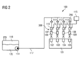
- FIG. 2 schematically shows a fuel supply system 100.
- the fuel supply system 100 comprises the combustion engine 101.
- the combustion engine 101 is an internal combustion engine of a vehicle, in particular a diesel gasoline combustion engine.
- the system 100 further comprises a fuel reservoir 118 in which fuel 120 is stored.
- the fuel is diesel gasoline.
- the fuel reservoir 118 is hydraulically coupled via a pipe 117 to a multitude of apparatuses 300 with respective fuel pumps 110, 111, 112, and 113 and respective fuel injectors 106, 107, 108, and 109 as explained with respect to Figure 1 .
- the fuel pumps each are electrically driven by the electronic actuator 203.
- the electronic actuator is arranged to move the piston 202 of the fuel pump in response to an electrical signal received by the fuel pump.
- the movement of the piston of the fuel pump forced by the electric actuator delivers fuel out of the reservoir 118 to the respective fuel injector.
- the electronic actuator is an electromagnetic actuator.
- the electromagnetic actuator comprises the solenoid that interacts with the piston 202 of the fuel pump.
- the electronic actuator is a piezoelectric actuator.
- the fuel pumps each are hydraulically connected to one single fuel injector 106, 107, 108, and 109.
- the fuel injectors are arranged to inject fuel into combustion chambers 102, 103, 104, and 105 of the combustion engine 101, respectively.
- the system 100 further comprises a low pressure pump 114 that is hydraulically arranged upstream the fuel pumps 110 to 113 and that provides fuel out of the fuel reservoir 118 to the fuel pumps 110 to 113.
- the system 100 further comprises the engine control unit 115 for controlling the system.
- the engine controlling unit 115 is electrically coupled to each of the fuel pumps 110 to 113.
- the engine control unit 115 is arranged to control the fuel pumps 110 to 113 to deliver fuel out of the fuel reservoir 118 to the fuel injectors 106 to 109.
- the system 100 comprises as much apparatuses 300 as combustion chambers, for example four combustions chambers and four apparatuses.
- the system 100 comprises as much fuel pumps as fuel injectors, for example four fuel pumps and four fuel injectors.
- the system 100 comprises more than four apparatuses 300 as well as combustion chambers and fuel pumps respectively, such as six apparatuses and combustion chambers respectively.
- the system 100 comprises less than four apparatuses 300, such as two apparatuses and combustion chambers respectively.
- One fuel pump 110 delivers fuel to exactly one fuel injector 106. Downstream the fuel pumps, the fuel injectors 106 to 109 are hydraulically independent from each other. Upstream of each fuel pump, the inlet valve 206 is arranged. There are as many inlet valves 206 as fuel pumps 110 to 113. The inlet valve 206 is a one-way valve and prevents fuel from returning in the direction to the fuel reservoir 118.
- fuel is delivered out of the fuel reservoir 118 to the fuel pumps 110 to 113 by the low pressure pump 114 via the pipe 117, and the respective valves 206.
- the fuel After sucking in fuel into the pump chamber 201 of the fuel pump 110 by moving the piston 202 in the x-direction due to the force of the spring 204, the fuel is provided under low-pressure in the pump chamber for being injected into the combustion chamber 102.
- the pump 110 does not eject the fuel out of the pump chamber as long as the actuator 203 is not energized by the motor control unit 115.
- the injector spring 217 is strong enough to hold the fuel injector in it's closed state against the low pressure as long as the actuator 203 is not energized.
- the engine control unit 115 controls the actuator to move in the opposite x-direction to eject the fuel out of the pump chamber, the respective fuel injector 106 opens and the fuel is ejected under pressure out of the pump chamber and injected into the combustion chamber 102 via the fuel injector 106. Afterwards, the engine control unit 115 stops the movement of the piston in the negative x-direction and therefore the fuel injector 106 moves again in its closed state and the pump 110 sucks in fuel.
- the functionality of the combination of the fuel pump 110, the fuel injector 106 and the combustion chamber 102 is transferable to the further combinations of the respective fuel pumps with the respective fuel injectors and combustion chambers, for example the combination of fuel pump 111 and the fuel injector 107 which form a further apparatus 300 as well as the combustion chamber 103.
- each fuel pump 110 to 113 provides fuel to only one fuel injector 106 to 109 respectively, the fuel injectors 106 to 109 are hydraulically independent from each other downstream the fuel pumps 110 to 113. Therefore, no pressure waves are generated that impact other fuel injectors. Furthermore, since the fuel pumps each comprise an electromagnetic or piezoelectric actuator, they are cost-effective. Each apparatus 300 is arranged to provide the fuel with a pressure of about 50 to 200 bar. Furthermore, due to the coupling of one fuel pump to one single fuel injector, there is no need for a common high-pressure rail that is coupled to a multitude of fuel injectors.
- the system 100 with the apparatus according to Figure 1 allows having the fuel pressure on demand and not only when the combustion engine 101 is running. Therefore, engine cranking is reliable because fuel pressure is readily available to allow proper storing conditions without turning the engine. This operation condition also supports a reliable stop/start function of the engine.
- the common high-pressure fuel rail is no longer required and the system 100 has a reduced number of components compared to conventional fuel supply systems.
- No fuel return line from the fuel pump to the fuel reservoir 118 is required.
- the system 100 is reliable especially when there are multiple injections of fuel into one combustion chamber during one engine cycle. Since the fuel pumps 110 to 113 each are electrically driven, there is no longer a need for providing an overpressure of 30% of additional injector P-Max performance as in conventional systems with a common fuel high-pressure rail. By the fuel pumps according to the system 100, there is the fuel provided at the pressure needed without a redundant additional pressure for balancing pressure pulsations. If the system 100 includes the ballistic operating condition function, the complete flow range could be obtained with one pressure value only.
Abstract
An apparatus for delivering fuel to a combustion engine comprises a fuel pump (110) with an electromagnetic or piezoelectric actuator (203) for driving the piston (202) and a fuel injector (106) that is hydraulically and mechanically coupled to an outlet (210) of the fuel pump (110). The fuel injector (106) comprises an open state in which a flow-through of the fuel through the fuel injector (106) is enabled and a closed state in which the flow-through of the fuel through the fuel injector (106) is prevented, wherein the fuel injector is designed to be shifted from the closed state to the open state due to the pressure affected by the pressurised fuel of the fuel pump (110).
Description
- The invention relates to an apparatus for delivering fuel to a combustion engine. Furthermore, the invention relates to a fuel supply system that comprises a multitude of such apparatuses.
- Conventional fuel supply systems in vehicles comprise a high-pressure fuel pump that is connected to a high-pressure rail. The fuel rail is hydraulically connected to a multitude of fuel injectors. The high-pressure fuel pump conventionally is driven by the camshaft of the combustion engine of the vehicle. Accordingly, the fuel pressure is only generated when the combustion engine is running, which is critical in particular during engine cranking. Conventionally, the fuel pressure is also a function of the revolutions per minute of the combustion engine because of the coupling of the high-pressure fuel pump with the camshaft of the combustion engine. Furthermore, the fuel injectors are all hydraulically coupled to one common high-pressure rail. Therefore, pressure waves are transmitted between the fuel injectors.
- A further aspect of the conventional system is that the components such as the fuel pumps or the common fuel rail are relatively expensive components because they must handle high-pressure fuel and be properly sealed.
- Additional engine management requirements like stop/start are look for a quick pressure build inside the injector to allow a quick injection to restart the engine. Also, engine cranking at low temperature requires high-pressure operating conditions to reduce engine emissions.
- It is desirable to create an apparatus for delivering fuel to a combustion engine that works reliably and is cost-effective. Furthermore, it is desirable to create a fuel supply system that works reliably and is cost-effective.
- According to an embodiment of the invention, an apparatus for delivering fuel to a combustion engine comprises a fuel pump. The apparatus further comprises a fuel injector that is hydraulically and mechanically coupled to an outlet of the fuel pump. The fuel pump comprises a pump housing with a pump chamber and a piston. The piston is arranged in the fuel pump such that it is axially movable in the pump chamber in order to provide a pressurization of the fuel within the pump chamber. The fuel pump further comprises an electromagnetic or piezoelectric actuator for driving the piston. The fuel injector comprises an open state in which a flow-through of the fuel through the fuel injector is enabled. The fuel injector further comprises a closed state in which the flow-through of the fuel through the fuel injector is prevented. The fuel injector is designed to be shifted from the closed state to the open state due to the pressure affected by the pressurized fuel of the fuel pump.
- The fuel pump is arranged to deliver fuel out of a fuel reservoir to exactly one fuel injector. Since the fuel pump is electrically driven, it is cost-effective. The fuel pump is arranged to be operated independent of the combustion engine since it is electrically driven and not driven by the camshaft of the combustion engine. The fuel pump is arranged to provide the fuel with a pressure of about 50 to 200 bar.
- The fuel injector is arranged to shift from the closed state to the open state only due to the force affected by the pressurized fuel of the fuel pump. The fuel injector comprises an outward opening design. The fuel injector comprises no separate electrical actuator and, therefore, no additional electrical signal to correctly open the fuel injector is necessary.
- According to further aspects, the electromagnetic or piezoelectric actuator is arranged to drive the piston in a first direction in order to provide the pressurization of the fuel and the fuel pump comprises a spring coupled to the piston for driving the piston in a second direction opposite the first direction to suck in the fuel into the pump chamber. The spring is arranged to apply a force to the piston that is as strong as needed to suck in the fuel into the pump chamber. The actuator is designed to apply a force that is strong enough to overcome the force of the spring and to pressurize the fuel with the pressure needed.
- According to further aspects, the apparatus further comprises a magnet that is coupled with the pump housing for driving the piston in the second direction. For example, the magnet is a permanent magnet. The magnet supports the spring in moving the piston in the second direction.
- According to further aspects, the fuel injector comprises an injector body including a central longitudinal axis. The injector body comprises a cavity with a fuel inlet portion and a fuel outlet portion.
- The fuel injector further comprises an injector needle axially movable in the cavity. The injector needle is designed to prevent a fuel flow through the fuel outlet portion in the closed state and releasing the fuel flow through the fuel outlet portion in the open state. The fuel injector further comprises an injector spring which is coupled to the injector needle. The injector spring is arranged to force the injector needle to move in the closed state.
- The fuel injector is controlled by the pressure of the fuel provided by the fuel pump. The fuel injector releases the fuel flow through the fuel outlet portion when the pressure of the fuel provided by the fuel pump is greater than the force of the injector spring.
- According to a further embodiment of the invention, a fuel supply system for a combustion engine comprises a multitude of apparatuses as described above. The combustion engine comprises a multitude of combustion chambers. The system comprises as much apparatuses as the combustion engine comprises combustion chambers and each apparatus of the multitude of apparatuses is arranged to deliver fuel to one combustion chamber of the multitude of combustion chambers, respectively.
- Reference will now be made in detail to embodiments of the invention, examples of which are illustrated in the accompanying drawings. Elements of the same design and function that appear in different figures are identified by the same reference signs.
- Figure 1
- schematically shows an apparatus according to an embodiment, and
- Figure 2
- schematically shows a fuel supply system according to an embodiment.
-
Figure 1 schematically shows anapparatus 300 for delivering fuel to a combustion engine 101 (Figure 2 ) . Theapparatus 300 comprises afuel pump 110 and afuel injector 106. - The
fuel pump 110 comprises apump housing 200. Thepump housing 200 surrounds apump chamber 201. A piston 202 is axially movably arranged in thepump chamber 201. The piston 202 is coupled to anactuator 203. The piston is further coupled to aspring 204. Thepump housing 200 has a spring rest and the piston 202 comprises a spring rest. Thespring 204 is arranged between the two spring rests. In particular, the piston 202 is coupled to anarmature 207. Thearmature 207 is arranged to interact with theactuator 203. Abellow 208 surrounds the piston as to separate the piston 202 from the magnetic circuit and, accordingly, theactuator 203 to protect the magnetic circuit from the fuel. Thepump 110 further comprises aninlet valve 206 through which fuel is sucked into thepump chamber 201 during operation of the fuel pump. The fuel is ejected out of thepump chamber 201 through anoutlet 210. Theinlet valve 206 and theoutlet 210 are hydraulically coupled with thepump chamber 201. Thefuel pump 110 further comprises aconnector 211 for connecting the pump with an engine control unit 115 (Figure 2 ). In particular, theactuator 203 is electrically coupled to theengine control unit 115. - The
fuel injector 106 comprises aninjector body 212. Theinjector body 212 surrounds acavity 213 with afuel inlet portion 214 and afuel outlet portion 215. Thefuel injector 106 further comprises aninjector needle 216 which is axially movable in thecavity 213. The fuel injector further comprises aninjector spring 217 which is coupled to theinjector needle 216 and theinjector body 212. Theinjector spring 217 forces the injector needle to a closed state in which a fuel flow through thefuel outlet portion 215 is prevented. Theinjector needle 216 is movable out of the closed state against the force of thespring 217 in an open state in which the fuel flow through thefuel outlet portion 215 is released. - The
fuel injector 106, in particular theinjector body 212, is coupled to thefuel pump 110, in particular to thepump housing 200. Thefuel injector 106 is directly coupled to thefuel pump 110. Theinjector body 212 is in contact with thepump housing 200. Thefuel injector 106 is hydraulically coupled with thepump 110. Theoutlet 210 of thepump 110 is hydraulically coupled with theinlet portion 214 of theinjector 106. Fuel is deliverable out of thepump chamber 201 through theoutlet 210 to thecavity 213. - The
fuel pump 110 comprises asecond spring 209 which is coupled to the piston, in particular to thearmature 207. Thesecond spring 209 is a calibration spring for calibrating the pressure that is provided by thepump 110. In further embodiments, thesecond spring 209 is arranged for calibrating the force applied to the piston when sucking in fuel into the pump chamber. - According to further embodiments, the
pump 110 comprises a magnet that is coupled with the pump housing for driving the piston in the x-direction ofFigure 1 . The magnet in particular is a permanent magnet and supports thespring 204 in moving the piston in the x-direction. When the solenoid of theactuator 203 is energized, the magnet exerts a force in the opposite x-direction and supports the pressurization of the fuel. This allows to have astronger spring 204 which acts against the movement in the opposite x-direction. This leads to a quicker sucking in of the fuel. - For delivering fuel to a
combustion chamber 102 of the combustion engine 101 (Figure 2 ), theengine control unit 115 controls thepump 110, especially theactuator 203, to move the piston axially in thepump chamber 201 in the opposite x-direction ofFigure 1 . This movement is against the force of thespring 204. Due to the movement of the piston, fuel that is in thepump chamber 201 is pressurized by the piston. The pressurized fuel exerts a force on theinjector needle 216. Due to the force applied by the pressurized fuel, the injector needle is moved against the force of thespring 217 in the opposite x-direction. Therefore, thefuel injector 106 has an outward opening injector design. - When enough fuel is injected into the
combustion chamber 102, the energizing of theactuator 203 is stopped. Therefore, no force in the opposite x-direction is applied to the piston 202 and the fuel in the pump chamber is no longer pressurized. At the same time, thespring 204 moves the piston 202 in the x-direction. Furthermore, theinjector needle 216 moves in its closed state. The closing of theinjector needle 216 is supported by theinjector needle 216 after the fuel pressure in thecavity 213 and thepump chamber 201 is reduced. When the force of thespring 217 in the x-direction is higher than the fuel pressure force, the closing of thefuel injector 106 begins. Due to the low displacement and due to the fact that no high residual fuel pressure is to be overcome, the closing will be very fast. - During the movement of the piston 202 in the x-direction, fuel that may be provided by a low-pressure pump 114 (
Figure 2 ) is suck into thepump chamber 201 via theinlet valve 206. Theinlet valve 206 is a one-way valve which prevents fuel from flowing out of thepump chamber 201 into the regions of the fuel supply system upstream thepump 110. - The volume of the pump chamber 202 is higher than the maximum fuel quantity that the
apparatus 300 is supposed to deliver during one cycle of the combustion engine. More fuel may be stored in the pump chamber 202 than theapparatus 300 is supposed to deliver during one engine cycle. - The
pump 110, which is electronically driven by the electromagnetic orpiezoelectric actuator 203, is only driven by electric energy during the fuel outtake phase when pressurized fuel is injected into the combustion chamber of the combustion engine. The energy to suck in fuel into the pump chamber is coming from thespring 204. The energy stored in thespring 204 is the only energy to perform the fuel intake. No additional energy is needed to suck in the fuel into the pump chamber. Electronic energy is only required to eject fuel out of the pump chamber. - Therefore, energy is saved and the efficiency of the apparatus is improved.
- In the
pump 110, no pressure pulsations are generated during the ejecting phase of the fuel. Further, thepump 110 with theelectric actuator 203 is arranged to provide pressurized fuel to the fuel injector independent from thecombustion engine 101, especially independent from the revolutions per minute of the combustion engine. Thepump 110 is not coupled to the camshaft of the combustion engine and therefore is arranged to provide pressurized fuel also when the camshaft is not turning. - During cranking of the combustion engine or by a stop/start function of the combustion engine, the
pump 110 is arranged to pressurize the fuel without engine rotation since the electrical signal to control thepump 110 can be sent to the pump by theengine control unit 115 at any time regardless of the engine rotation speed. Thepump 110 is also arranged to pressurize only the fuel required by thefuel injector 106 by the next injection and there is no large waste or inefficiency as per the conventional mechanically driven high-pressure pumps. - The
fuel pump 110 and thefuel injector 106 are part of the same product. Thefuel pump 110 comprises a single piston, is electrically driven and allows to be driven only during the injection event to generate the fuel pressure and to deliver the required fuel quantity to the combustion engine. The energy required to pressurize the fuel and to perform the injection event is significantly reduced in comparison with the current system design with a mechanically driven high pressure pump and a common rail high pressure rail. Furthermore, since the fuel injector opening is generated by the fuel pressure, it does not require a separate electrical signal to correctly open the fuel injector. Theapparatus 300 comprising thefuel pump 110 and thefuel injector 106 needs one single electrical signal to control the pumping and to perform the fuel injection into the combustion chamber. The required fuel pressure values are achieved with less energy consumption with respect to the current systems that comprise a high-pressure pump driven by the camshaft of the combustion engine and that comprise a single high-pressure rail to which all of the fuel injectors are connected. -
Figure 2 schematically shows afuel supply system 100. Thefuel supply system 100 comprises thecombustion engine 101. Thecombustion engine 101 is an internal combustion engine of a vehicle, in particular a diesel gasoline combustion engine. - The
system 100 further comprises afuel reservoir 118 in which fuel 120 is stored. In particular, the fuel is diesel gasoline. Thefuel reservoir 118 is hydraulically coupled via apipe 117 to a multitude ofapparatuses 300 withrespective fuel pumps respective fuel injectors Figure 1 . The fuel pumps each are electrically driven by theelectronic actuator 203. The electronic actuator is arranged to move the piston 202 of the fuel pump in response to an electrical signal received by the fuel pump. The movement of the piston of the fuel pump forced by the electric actuator delivers fuel out of thereservoir 118 to the respective fuel injector. In particular the electronic actuator is an electromagnetic actuator. The electromagnetic actuator comprises the solenoid that interacts with the piston 202 of the fuel pump. According to further embodiments, the electronic actuator is a piezoelectric actuator. - The fuel pumps each are hydraulically connected to one
single fuel injector combustion chambers combustion engine 101, respectively. - The
system 100 further comprises alow pressure pump 114 that is hydraulically arranged upstream the fuel pumps 110 to 113 and that provides fuel out of thefuel reservoir 118 to the fuel pumps 110 to 113. - The
system 100 further comprises theengine control unit 115 for controlling the system. Theengine controlling unit 115 is electrically coupled to each of the fuel pumps 110 to 113. Theengine control unit 115 is arranged to control the fuel pumps 110 to 113 to deliver fuel out of thefuel reservoir 118 to thefuel injectors 106 to 109. - The
system 100 comprises asmuch apparatuses 300 as combustion chambers, for example four combustions chambers and four apparatuses. Thesystem 100 comprises as much fuel pumps as fuel injectors, for example four fuel pumps and four fuel injectors. According to further embodiments, thesystem 100 comprises more than fourapparatuses 300 as well as combustion chambers and fuel pumps respectively, such as six apparatuses and combustion chambers respectively. According to further embodiments, thesystem 100 comprises less than fourapparatuses 300, such as two apparatuses and combustion chambers respectively. - One
fuel pump 110 delivers fuel to exactly onefuel injector 106. Downstream the fuel pumps, thefuel injectors 106 to 109 are hydraulically independent from each other. Upstream of each fuel pump, theinlet valve 206 is arranged. There are asmany inlet valves 206 asfuel pumps 110 to 113. Theinlet valve 206 is a one-way valve and prevents fuel from returning in the direction to thefuel reservoir 118. - During operation, fuel is delivered out of the
fuel reservoir 118 to the fuel pumps 110 to 113 by thelow pressure pump 114 via thepipe 117, and therespective valves 206. - After sucking in fuel into the
pump chamber 201 of thefuel pump 110 by moving the piston 202 in the x-direction due to the force of thespring 204, the fuel is provided under low-pressure in the pump chamber for being injected into thecombustion chamber 102. Thepump 110 does not eject the fuel out of the pump chamber as long as theactuator 203 is not energized by themotor control unit 115. Theinjector spring 217 is strong enough to hold the fuel injector in it's closed state against the low pressure as long as theactuator 203 is not energized. - When the
engine control unit 115 controls the actuator to move in the opposite x-direction to eject the fuel out of the pump chamber, therespective fuel injector 106 opens and the fuel is ejected under pressure out of the pump chamber and injected into thecombustion chamber 102 via thefuel injector 106. Afterwards, theengine control unit 115 stops the movement of the piston in the negative x-direction and therefore thefuel injector 106 moves again in its closed state and thepump 110 sucks in fuel. - There is only one sucking in and only one ejecting of fuel out of the
pump 110 per one injection of fuel into thecombustion chamber 102 via thefuel injector 106. Per one ejecting of the fuel out of the pump chamber of thepump 110 there is one opening of thefuel injector 106. - The functionality of the combination of the
fuel pump 110, thefuel injector 106 and thecombustion chamber 102 is transferable to the further combinations of the respective fuel pumps with the respective fuel injectors and combustion chambers, for example the combination offuel pump 111 and thefuel injector 107 which form afurther apparatus 300 as well as thecombustion chamber 103. - Since each
fuel pump 110 to 113 provides fuel to only onefuel injector 106 to 109 respectively, thefuel injectors 106 to 109 are hydraulically independent from each other downstream the fuel pumps 110 to 113. Therefore, no pressure waves are generated that impact other fuel injectors. Furthermore, since the fuel pumps each comprise an electromagnetic or piezoelectric actuator, they are cost-effective. Eachapparatus 300 is arranged to provide the fuel with a pressure of about 50 to 200 bar. Furthermore, due to the coupling of one fuel pump to one single fuel injector, there is no need for a common high-pressure rail that is coupled to a multitude of fuel injectors. - The
system 100 with the apparatus according toFigure 1 allows having the fuel pressure on demand and not only when thecombustion engine 101 is running. Therefore, engine cranking is reliable because fuel pressure is readily available to allow proper storing conditions without turning the engine. This operation condition also supports a reliable stop/start function of the engine. The common high-pressure fuel rail is no longer required and thesystem 100 has a reduced number of components compared to conventional fuel supply systems. No fuel return line from the fuel pump to thefuel reservoir 118 is required. No on/off digital valve in thepipe 117 between thelow pressure pump 114 and theapparatuses 300. Since each fuel pump is responsible to supply high-pressure fuel to exactly one fuel injector, there are no or less pressure pulsations transmitted between the fuel pumps 110 to 113 and thefuel injectors 106 to 109. There is no influence from one apparatus to the other apparatuses. No pressure waves are transmitted between the fuel injectors due to any injection event. - The
system 100 is reliable especially when there are multiple injections of fuel into one combustion chamber during one engine cycle. Since the fuel pumps 110 to 113 each are electrically driven, there is no longer a need for providing an overpressure of 30% of additional injector P-Max performance as in conventional systems with a common fuel high-pressure rail. By the fuel pumps according to thesystem 100, there is the fuel provided at the pressure needed without a redundant additional pressure for balancing pressure pulsations. If thesystem 100 includes the ballistic operating condition function, the complete flow range could be obtained with one pressure value only.
Claims (8)
- Apparatus for delivering fuel to a combustion engine, comprising:- a fuel pump (110),- a fuel injector (106) that is hydraulically and mechanically coupled to an outlet (210) of the fuel pump (110), with- the fuel pump (110) comprising a pump housing (200) with a pump chamber (201) and a piston (202), with the piston (202) being arranged in the fuel pump such that it is axially moveable in the pump chamber (201) in order to provide a pressurisation of the fuel within the pump chamber (201) and an electromagnetic or piezoelectric actuator (203) for driving the piston (202) and- the fuel injector (106) comprising an open state in which a flow-through of the fuel through the fuel injector (106) is enabled and a closed state in which the flow-through of the fuel through the fuel injector (106) is prevented, wherein the fuel injector is designed to be shifted from the closed state to the open state due to the pressure affected by the pressurised fuel of the fuel pump (110).
- Apparatus according to claim 1, wherein the actuator (203) is arranged to drive the piston (202) in a first direction in order to provide the pressurisation of the fuel and the fuel pump comprises a spring (204) coupled to the piston (202) for driving the piston (202) in a second direction opposite to the first direction to suck in the fuel into the pump chamber (201).
- Apparatus according to claim 2, comprising a magnet that is coupled with the pump housing for driving the piston (202) in the second direction.
- Apparatus according to one of claims 1 to 3, wherein the fuel injector (106) comprises- an injector body (212) including a central longitudinal axis (L), the injector body (212) comprising a cavity (213) with a fuel inlet portion (214) and a fuel outlet portion (215),- an injector needle (216) axially movable in the cavity (213), the injector needle (216) preventing a fuel flow through the fuel outlet portion (215) in the closed state and releasing the fuel flow through the fuel outlet portion (215) in the open state, and- an injector spring (217), with the injector spring being coupled to the injector needle (216), the injector spring (217) being arranged to force the injector needle (216) to move in the closed state.
- Apparatus according to one of claims 1 to 4, with the fuel injector (106) being directly coupled to the fuel pump (110).
- Apparatus according to one of claims 1 to 5, with the fuel pump being arranged to be operated independent of the combustion engine (101).
- Fuel supply system for a combustion engine (101), with the combustion engine (101) comprising a multitude of combustion chambers (102, 103, 104, 105), comprising:- a multitude of apparatuses (300) according to any of claims 1 to 6, wherein the system comprises as much apparatuses as the combustion engine (101) comprises combustion chambers (102, 103, 104, 105) and wherein each apparatus of the multitude of apparatuses is arranged to deliver fluid to one combustion chamber (102) of the multitude of combustion chambers (102, 103, 104, 105) respectively.
- Fuel supply system according to claim 7, further comprising an engine control unit (115) for controlling the multitude of apparatuses (300), with each apparatus (300) being arranged to pressurize the fuel and inject the fuel one time in response to one single common control signal from the engine control unit (115).
Priority Applications (1)
| Application Number | Priority Date | Filing Date | Title |
|---|---|---|---|
| EP11156989A EP2495428A1 (en) | 2011-03-04 | 2011-03-04 | Apparatus for delivering fuel and fuel supply system |
Applications Claiming Priority (1)
| Application Number | Priority Date | Filing Date | Title |
|---|---|---|---|
| EP11156989A EP2495428A1 (en) | 2011-03-04 | 2011-03-04 | Apparatus for delivering fuel and fuel supply system |
Publications (1)
| Publication Number | Publication Date |
|---|---|
| EP2495428A1 true EP2495428A1 (en) | 2012-09-05 |
Family
ID=44022373
Family Applications (1)
| Application Number | Title | Priority Date | Filing Date |
|---|---|---|---|
| EP11156989A Withdrawn EP2495428A1 (en) | 2011-03-04 | 2011-03-04 | Apparatus for delivering fuel and fuel supply system |
Country Status (1)
| Country | Link |
|---|---|
| EP (1) | EP2495428A1 (en) |
Cited By (1)
| Publication number | Priority date | Publication date | Assignee | Title |
|---|---|---|---|---|
| WO2016039922A1 (en) * | 2014-09-08 | 2016-03-17 | Qualcomm Incorporated | Time budget management for wlan and wwan processing for inter-frequency/inter-rat measurements for lte |
Citations (5)
| Publication number | Priority date | Publication date | Assignee | Title |
|---|---|---|---|---|
| US6398511B1 (en) * | 2000-08-18 | 2002-06-04 | Bombardier Motor Corporation Of America | Fuel injection driver circuit with energy storage apparatus |
| EP1367255A1 (en) * | 2001-02-16 | 2003-12-03 | Daguang Xi | Electrically operated fuel injection apparatus |
| EP1715177A1 (en) * | 2005-04-21 | 2006-10-25 | Dell'orto S.P.A. | Piezoelectric actuator for the operation of an injection pump for internal-combustion engines, and injector-pump assembly employing said actuator |
| DE102008007349A1 (en) * | 2008-02-04 | 2009-08-06 | Robert Bosch Gmbh | Compact injection device with reduced steam bubble inclination |
| US20100101537A1 (en) * | 2007-02-28 | 2010-04-29 | Scion-Sprays Limited | Method Of Fuel Injection |
-
2011
- 2011-03-04 EP EP11156989A patent/EP2495428A1/en not_active Withdrawn
Patent Citations (5)
| Publication number | Priority date | Publication date | Assignee | Title |
|---|---|---|---|---|
| US6398511B1 (en) * | 2000-08-18 | 2002-06-04 | Bombardier Motor Corporation Of America | Fuel injection driver circuit with energy storage apparatus |
| EP1367255A1 (en) * | 2001-02-16 | 2003-12-03 | Daguang Xi | Electrically operated fuel injection apparatus |
| EP1715177A1 (en) * | 2005-04-21 | 2006-10-25 | Dell'orto S.P.A. | Piezoelectric actuator for the operation of an injection pump for internal-combustion engines, and injector-pump assembly employing said actuator |
| US20100101537A1 (en) * | 2007-02-28 | 2010-04-29 | Scion-Sprays Limited | Method Of Fuel Injection |
| DE102008007349A1 (en) * | 2008-02-04 | 2009-08-06 | Robert Bosch Gmbh | Compact injection device with reduced steam bubble inclination |
Cited By (2)
| Publication number | Priority date | Publication date | Assignee | Title |
|---|---|---|---|---|
| WO2016039922A1 (en) * | 2014-09-08 | 2016-03-17 | Qualcomm Incorporated | Time budget management for wlan and wwan processing for inter-frequency/inter-rat measurements for lte |
| US9462600B2 (en) | 2014-09-08 | 2016-10-04 | Qualcomm Incorporated | Time budget management for WLAN and WWAN processing for inter-frequency/inter-rat measurements for LTE |
Similar Documents
| Publication | Publication Date | Title |
|---|---|---|
| JP4353288B2 (en) | Fuel pump | |
| EP2317105B1 (en) | High-pressure fuel supply pump and fuel supply system | |
| US4777921A (en) | Fuel injection system | |
| EP1965069A2 (en) | Control valve for a gas direkt injection fuel system | |
| KR20130056858A (en) | High-pressure pump | |
| JP2006144802A (en) | Control method of pressure-feeding quantity of fuel high-pressure pump for internal combustion engine, computer program, open control and/or closed loop control device for driving internal combustin engine, and fuel high-pressure pump for internal combustion engine | |
| WO2006060545A1 (en) | Reduced noise solenoid controlled fuel pump | |
| CN103998764B (en) | Spraying system | |
| EP2241744A1 (en) | Common Rail Fuel Pump and Control Method for a Common Rail Fuel Pump | |
| WO2010019403A2 (en) | Check valve with separate spherical spring guide | |
| US11401883B2 (en) | System and method for direct injection fuel pump control | |
| EP2495428A1 (en) | Apparatus for delivering fuel and fuel supply system | |
| US20050045149A1 (en) | Fuel injection system | |
| EP2495429A1 (en) | Fuel pump for delivering fuel to a fuel injector and system comprising a multitude of such fuel pumps | |
| US20070217925A1 (en) | Variable discharge pump | |
| US7066151B1 (en) | Fuel injector with spill chamber | |
| JP5528754B2 (en) | Fuel injection system with high pressure pump with magnetically actuable intake valve | |
| JP2009185609A (en) | Fuel injection device for multiple cylinder internal combustion engine | |
| JP2009103008A (en) | Fuel pump | |
| JP4404056B2 (en) | Fuel injection device for internal combustion engine | |
| US20090140187A1 (en) | Pressure control valve | |
| EP0992675A2 (en) | Fuel system | |
| EP2495430A1 (en) | Fuel supply system and method for delivering fuel to a fuel injector | |
| US10830194B2 (en) | Common rail fuel system having pump-accumulator injectors | |
| US20040099246A1 (en) | Fuel injector with multiple control valves |
Legal Events
| Date | Code | Title | Description |
|---|---|---|---|
| PUAI | Public reference made under article 153(3) epc to a published international application that has entered the european phase |
Free format text: ORIGINAL CODE: 0009012 |
|
| AK | Designated contracting states |
Kind code of ref document: A1 Designated state(s): AL AT BE BG CH CY CZ DE DK EE ES FI FR GB GR HR HU IE IS IT LI LT LU LV MC MK MT NL NO PL PT RO RS SE SI SK SM TR |
|
| AX | Request for extension of the european patent |
Extension state: BA ME |
|
| STAA | Information on the status of an ep patent application or granted ep patent |
Free format text: STATUS: THE APPLICATION IS DEEMED TO BE WITHDRAWN |
|
| 18D | Application deemed to be withdrawn |
Effective date: 20130306 |