EP2495344A1 - Electrode foil and capacitor using same - Google Patents
Electrode foil and capacitor using same Download PDFInfo
- Publication number
- EP2495344A1 EP2495344A1 EP10826293A EP10826293A EP2495344A1 EP 2495344 A1 EP2495344 A1 EP 2495344A1 EP 10826293 A EP10826293 A EP 10826293A EP 10826293 A EP10826293 A EP 10826293A EP 2495344 A1 EP2495344 A1 EP 2495344A1
- Authority
- EP
- European Patent Office
- Prior art keywords
- electrode foil
- zirconium
- foil
- capacitor
- aluminum
- Prior art date
- Legal status (The legal status is an assumption and is not a legal conclusion. Google has not performed a legal analysis and makes no representation as to the accuracy of the status listed.)
- Withdrawn
Links
- 239000011888 foil Substances 0.000 title claims abstract description 124
- 239000003990 capacitor Substances 0.000 title claims description 52
- QCWXUUIWCKQGHC-UHFFFAOYSA-N Zirconium Chemical compound [Zr] QCWXUUIWCKQGHC-UHFFFAOYSA-N 0.000 claims abstract description 44
- 229910052726 zirconium Inorganic materials 0.000 claims abstract description 40
- 229910052782 aluminium Inorganic materials 0.000 claims abstract description 27
- XAGFODPZIPBFFR-UHFFFAOYSA-N aluminium Chemical compound [Al] XAGFODPZIPBFFR-UHFFFAOYSA-N 0.000 claims abstract description 27
- 229910000838 Al alloy Inorganic materials 0.000 claims abstract description 14
- 239000000203 mixture Substances 0.000 claims abstract description 10
- 229910000765 intermetallic Inorganic materials 0.000 claims description 14
- 239000007784 solid electrolyte Substances 0.000 claims description 8
- 239000008151 electrolyte solution Substances 0.000 claims description 6
- 238000005530 etching Methods 0.000 description 15
- 238000010438 heat treatment Methods 0.000 description 11
- 229910001093 Zr alloy Inorganic materials 0.000 description 7
- ZGUQGPFMMTZGBQ-UHFFFAOYSA-N [Al].[Al].[Zr] Chemical compound [Al].[Al].[Zr] ZGUQGPFMMTZGBQ-UHFFFAOYSA-N 0.000 description 7
- 238000002048 anodisation reaction Methods 0.000 description 5
- 230000000052 comparative effect Effects 0.000 description 5
- 239000003792 electrolyte Substances 0.000 description 5
- 239000011347 resin Substances 0.000 description 5
- 229920005989 resin Polymers 0.000 description 5
- 239000007787 solid Substances 0.000 description 5
- QAOWNCQODCNURD-UHFFFAOYSA-N Sulfuric acid Chemical compound OS(O)(=O)=O QAOWNCQODCNURD-UHFFFAOYSA-N 0.000 description 4
- 239000007864 aqueous solution Substances 0.000 description 4
- 239000011248 coating agent Substances 0.000 description 4
- 238000000576 coating method Methods 0.000 description 4
- 229920001940 conductive polymer Polymers 0.000 description 4
- 239000013078 crystal Substances 0.000 description 4
- 238000005259 measurement Methods 0.000 description 4
- 229910052751 metal Inorganic materials 0.000 description 4
- 239000002184 metal Substances 0.000 description 4
- 238000000034 method Methods 0.000 description 4
- 239000002244 precipitate Substances 0.000 description 3
- 238000007789 sealing Methods 0.000 description 3
- OKTJSMMVPCPJKN-UHFFFAOYSA-N Carbon Chemical compound [C] OKTJSMMVPCPJKN-UHFFFAOYSA-N 0.000 description 2
- XEEYBQQBJWHFJM-UHFFFAOYSA-N Iron Chemical compound [Fe] XEEYBQQBJWHFJM-UHFFFAOYSA-N 0.000 description 2
- PXHVJJICTQNCMI-UHFFFAOYSA-N Nickel Chemical compound [Ni] PXHVJJICTQNCMI-UHFFFAOYSA-N 0.000 description 2
- 238000007743 anodising Methods 0.000 description 2
- 230000015572 biosynthetic process Effects 0.000 description 2
- 229910052799 carbon Inorganic materials 0.000 description 2
- 239000012535 impurity Substances 0.000 description 2
- 238000004804 winding Methods 0.000 description 2
- 239000004254 Ammonium phosphate Substances 0.000 description 1
- VEXZGXHMUGYJMC-UHFFFAOYSA-M Chloride anion Chemical compound [Cl-] VEXZGXHMUGYJMC-UHFFFAOYSA-M 0.000 description 1
- RYGMFSIKBFXOCR-UHFFFAOYSA-N Copper Chemical compound [Cu] RYGMFSIKBFXOCR-UHFFFAOYSA-N 0.000 description 1
- OTRAYOBSWCVTIN-UHFFFAOYSA-N OB(O)O.OB(O)O.OB(O)O.OB(O)O.OB(O)O.N.N.N.N.N.N.N.N.N.N.N.N.N.N.N Chemical compound OB(O)O.OB(O)O.OB(O)O.OB(O)O.OB(O)O.N.N.N.N.N.N.N.N.N.N.N.N.N.N.N OTRAYOBSWCVTIN-UHFFFAOYSA-N 0.000 description 1
- BQCADISMDOOEFD-UHFFFAOYSA-N Silver Chemical compound [Ag] BQCADISMDOOEFD-UHFFFAOYSA-N 0.000 description 1
- 230000002378 acidificating effect Effects 0.000 description 1
- 239000000654 additive Substances 0.000 description 1
- 239000000853 adhesive Substances 0.000 description 1
- PNEYBMLMFCGWSK-UHFFFAOYSA-N aluminium oxide Inorganic materials [O-2].[O-2].[O-2].[Al+3].[Al+3] PNEYBMLMFCGWSK-UHFFFAOYSA-N 0.000 description 1
- ZRSKSQHEOZFGLJ-UHFFFAOYSA-N ammonium adipate Chemical compound [NH4+].[NH4+].[O-]C(=O)CCCCC([O-])=O ZRSKSQHEOZFGLJ-UHFFFAOYSA-N 0.000 description 1
- 235000019293 ammonium adipate Nutrition 0.000 description 1
- 229910000148 ammonium phosphate Inorganic materials 0.000 description 1
- 235000019289 ammonium phosphates Nutrition 0.000 description 1
- 238000005452 bending Methods 0.000 description 1
- 229910052802 copper Inorganic materials 0.000 description 1
- 239000010949 copper Substances 0.000 description 1
- 238000006298 dechlorination reaction Methods 0.000 description 1
- MNNHAPBLZZVQHP-UHFFFAOYSA-N diammonium hydrogen phosphate Chemical compound [NH4+].[NH4+].OP([O-])([O-])=O MNNHAPBLZZVQHP-UHFFFAOYSA-N 0.000 description 1
- 238000001035 drying Methods 0.000 description 1
- 238000009499 grossing Methods 0.000 description 1
- 229910052742 iron Inorganic materials 0.000 description 1
- 238000010030 laminating Methods 0.000 description 1
- 239000007788 liquid Substances 0.000 description 1
- 230000014759 maintenance of location Effects 0.000 description 1
- VNWKTOKETHGBQD-UHFFFAOYSA-N methane Chemical compound C VNWKTOKETHGBQD-UHFFFAOYSA-N 0.000 description 1
- 239000011259 mixed solution Substances 0.000 description 1
- 238000002156 mixing Methods 0.000 description 1
- 229910052759 nickel Inorganic materials 0.000 description 1
- 239000012299 nitrogen atmosphere Substances 0.000 description 1
- 239000000615 nonconductor Substances 0.000 description 1
- 239000002861 polymer material Substances 0.000 description 1
- 230000001376 precipitating effect Effects 0.000 description 1
- 238000001556 precipitation Methods 0.000 description 1
- 239000004065 semiconductor Substances 0.000 description 1
- 229910052710 silicon Inorganic materials 0.000 description 1
- 239000010703 silicon Substances 0.000 description 1
- 229910052709 silver Inorganic materials 0.000 description 1
- 239000004332 silver Substances 0.000 description 1
- 239000010935 stainless steel Substances 0.000 description 1
- 229910001220 stainless steel Inorganic materials 0.000 description 1
- 238000003466 welding Methods 0.000 description 1
Images

Classifications
-
- H—ELECTRICITY
- H01—ELECTRIC ELEMENTS
- H01G—CAPACITORS; CAPACITORS, RECTIFIERS, DETECTORS, SWITCHING DEVICES, LIGHT-SENSITIVE OR TEMPERATURE-SENSITIVE DEVICES OF THE ELECTROLYTIC TYPE
- H01G9/00—Electrolytic capacitors, rectifiers, detectors, switching devices, light-sensitive or temperature-sensitive devices; Processes of their manufacture
- H01G9/004—Details
- H01G9/04—Electrodes or formation of dielectric layers thereon
- H01G9/042—Electrodes or formation of dielectric layers thereon characterised by the material
- H01G9/045—Electrodes or formation of dielectric layers thereon characterised by the material based on aluminium
-
- C—CHEMISTRY; METALLURGY
- C22—METALLURGY; FERROUS OR NON-FERROUS ALLOYS; TREATMENT OF ALLOYS OR NON-FERROUS METALS
- C22C—ALLOYS
- C22C21/00—Alloys based on aluminium
-
- Y—GENERAL TAGGING OF NEW TECHNOLOGICAL DEVELOPMENTS; GENERAL TAGGING OF CROSS-SECTIONAL TECHNOLOGIES SPANNING OVER SEVERAL SECTIONS OF THE IPC; TECHNICAL SUBJECTS COVERED BY FORMER USPC CROSS-REFERENCE ART COLLECTIONS [XRACs] AND DIGESTS
- Y10—TECHNICAL SUBJECTS COVERED BY FORMER USPC
- Y10T—TECHNICAL SUBJECTS COVERED BY FORMER US CLASSIFICATION
- Y10T428/00—Stock material or miscellaneous articles
- Y10T428/12—All metal or with adjacent metals
- Y10T428/12493—Composite; i.e., plural, adjacent, spatially distinct metal components [e.g., layers, joint, etc.]
- Y10T428/12736—Al-base component
- Y10T428/12764—Next to Al-base component
Definitions
- the present invention relates to electrode foil and a capacitor using the same.
- capacitors examples include a solid electrolytic capacitor having low ESR (equivalent series resistance) used in a periphery of a CPU (central processing unit) of a personal computer, an aluminum electrolytic capacitor used for smoothing a power supply circuit, and the like. These capacitors have been strongly demanded to have a smaller size and larger capacity.
- a solid electrolytic capacitor includes electrode foil (anode foil) having an oxide film formed on the surface thereof, a solid electrolyte layer made of a conductive polymer and formed on the oxide film, and a cathode current collector formed on the solid electrolyte layer.
- the solid electrolyte layer and the cathode current collector form a cathode layer.
- Electrode foil can be obtained by etching metal foil such as aluminum foil. Thus, the surface area of the electrode foil can be increased and the capacitance can be enhanced.
- Examples of the above-mentioned aluminum alloy foil include aluminum - zirconium alloy foil containing zirconium in aluminum. It is thought that, because the dielectric constant of an oxide of zirconium is high, use of the aluminum - zirconium alloy foil enhances the dielectric constant of an oxide film and thus contributes to improve the capacitance.
- the atomic ratio of zirconium is increased so as to enhance the dielectric constant of the oxide film and thereby to enhance the capacitance.
- the present invention improves capacitance of electrode foil.
- Electrode foil includes an aluminum alloy having a composition in a region at least 10 ⁇ m deep from a surface of the foil.
- the composition includes aluminum as a main component and zirconium of at least 0.03 at% and at most 0.5 at%.
- Electrode foil in accordance with a first exemplary embodiment of the present invention and a capacitor using the electrode foil are described with reference to drawings.
- the capacitor of this exemplary embodiment is a solid electrolytic capacitor using a conductive polymer material as an electrolyte.
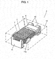
- Fig. 1 is a perspective view of a capacitor in accordance with the first exemplary embodiment of the present invention.
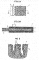
- Fig. 2A is a plan view of a capacitor element used in the capacitor in accordance with the first exemplary embodiment of the present invention, and
- Fig. 2B is a sectional view of the capacitor element.
- Fig. 2B shows a shape of a cross section taken along line 2B-2B in Fig. 2A .
- capacitor 2 is configured by laminating a plurality of capacitor elements 1 each having a plate shape.
- capacitor element 1 includes anode layer 5, cathode layer 7, and resist portion 6 (electrical insulator) for separating between anode layer 5 and cathode layer 7.
- capacitor element 1 includes electrode foil 4. On the surface of electrode foil 4, oxide film 3 is formed.
- Resist portion 6 is provided such that electrode foil 4 is pressed after oxide film 3 is formed on the surface of electrode foil 4. Resist portion 6 divides electrode foil 4 into anode layer 5 and a cathode formation part including cathode layer 7.
- Cathode layer 7 is formed on oxide film 3 of the cathode formation part.
- Cathode layer 7 includes solid electrolyte layer 8 made of a conductive polymer formed on oxide film 3, and cathode current collector 9 made of a carbon layer and a silver paste layer formed on solid electrolyte layer 8.
- anode layer 5 of each of the plurality of laminated capacitor elements 1 is connected to anode COM terminal 10 by laser welding.
- Cathode COM terminal 11 is connected to cathode layers 7.
- Cathode COM terminal 11 is provided with bent portion 11a. Bent portion 11a is formed by upwardly bending the both side surfaces of a portion on which capacitor elements 1 are placed.
- the portion of cathode COM terminal 11 on which the elements are mounted and cathode layer 7 of capacitor element 1, bent portion 11a and cathode layer 7, as well as cathode layers 7 of capacitor elements 1 can be joined with each other with an electric conductive adhesive agent, respectively.
- Anode COM terminal 10 and cathode COM terminal 11 together with a plurality of capacitor elements 1 are integrally covered with coating resin body 12 made of an insulating resin in a state in which a part of each of anode COM terminal 10 and cathode COM terminal 11 is exposed to the outer surface.
- the part of each of anode COM terminal 10 and cathode COM terminal 11 expressing from coating resin body 12 is bent toward the bottom surface along coating resin body 12.
- Fig. 3 is a schematic sectional view of electrode foil 4 in accordance with the first exemplary embodiment of the present invention.
- the surface of electrode foil 4 is etched so as to form fine pits 13.
- electrode foil 4 having a thickness of 70 to 120 ⁇ m is usually etched to the depth of about 30 to 35 ⁇ m.
- electrode foil 4 is etched to the depth of at least 10 ⁇ m or more, sufficient capacitance can be ensured.
- etching of electrode foil 4 as an etchant, a mixed solution obtained by mixing sulfuric acid as additives into an acidic aqueous solution having a chlorine ion concentration of 2.75 N so that the sulfuric acid concentration is 0.1% is used.
- a plain (non-etched) state electrode foil 4 is impregnated with the etchant.
- An etching process is carried out by setting one carbon electrode each on both sides of electrode foil 4, and applying an alternating current to the two carbon electrodes. At this time, an AC power supply condition is adjusted so that etching reduction amount per unit area of electrode foil 4 is 10 mg/cm 2 . After that, dechlorination and drying are carried out so as to produce etched electrode foil 4.
- oxide film 3 is formed along the shape of fine pits 13 formed on the surface of electrode foil 4.
- Oxide film 3 is formed by anodizing electrode foil 4.
- the film thickness of oxide film 3 in this exemplary embodiment is about 0.01 ⁇ m.
- etched electrode foil 4 is anodized under conditions of an anodization voltage of 4.5 V, and a retention time of 20 minutes, with 0.3% ammonium phosphate aqueous solution at 70°C at 0.05 A/cm 2 .
- the capacitance of the electrode foil is measured under conditions in which 8% ammonium pentaborate aqueous solution is used, the measurement temperature is 30°C, the measurement area is 10 cm 2 , the measurement frequency is 120 Hz, and an impedance analyzer or an LCR meter are used.
- Electrode foil 4 of this exemplary embodiment is made of an aluminum - zirconium alloy containing aluminum as a main component.
- the atomic ratio of zirconium in electrode foil 4 is about 0.03 atomic percent (at%) or more and 0.5 at% or less, and the atomic ratio of aluminum is about 99 at% or more.
- Electrode foil 4 includes inevitable impurities, including 64 ppm of silicon, 18 ppm of iron, 4 ppm of copper, nickel, and the like, in mass fraction, and other compositions in the mass fraction or less. These impurities are smaller than zirconium in terms of the mass fraction and the atomic ratio. That is to say, in the atomic ratio of electrode foil 4 in this exemplary embodiment, zirconium is the second largest to aluminum.
- Electrode foil 4 includes a plurality of intermetallic compounds any of which has a diameter of 1 ⁇ m or less.
- the composition of the intermetallic compound is Al 3 Zr.
- Fig. 4 is a graph showing an increasing rate of capacitance of electrode foil 4 in this exemplary embodiment in comparison with that of conventional electrode foil using aluminum foil.
- an atomic ratio of zirconium is less than 0.01 at% and an atomic ratio of aluminum is 99.9 at% or more.
- Both electrode foil 4 of this exemplary embodiment and the electrode foil of the comparative example are subjected to anodization after etching as mentioned above.
- Fig. 4 shows an increasing rate (%) of capacitance in the axis of ordinate, and shows that a reference value (0%) is the same value as the capacitance of the comparative example. Furthermore, the axis of abscissa of Fig. 4 shows the atomic ratio (at%) of zirconium in electrode foil 4. Note here that an actually measured value of the capacitance in the reference value (0%) is about 700 ⁇ F when electrode foil having a size of 1 cm ⁇ 2 cm is used.
- the capacitance of electrode foil 4 is increased as compared with the comparative example.
- the atomic ratio of zirconium is more than 0.5 at%, large intermetallic compounds having a diameter of 20 ⁇ m or more precipitate, and the diameter and the number thereof are increased as the atomic ratio increases.
- the intermetallic compounds are not etched and remain on the surface of electrode foil 4, which remarkably reduces the capacitance.
- the atomic ratio of zirconium is 0.9%, a large number of intermetallic compounds start to precipitate, and the capacitance is lowered as compared with the conventional example.
- the capacitance is lowered by as large as 80% as compared with the conventional example.
- intermetallic compounds having a diameter of larger than 1 ⁇ m also precipitate, but the size of the intermetallic compound is relatively smaller and the number thereof is smaller as compared with the case where the atomic ratio is more than 0.5 at%.
- the capacitance of electrode foil 4 can be increased. This is because the precipitation of the intermetallic compounds can be suppressed by reducing the content of zirconium as mentioned above. Therefore, according to this exemplary embodiment, electrode foil 4 can be finely etched, and the surface area can be enlarged and the capacitance can be increased.
- the dielectric constant of oxide film 3 can be remarkably increased, and the capacitance can be increased.
- the dielectric constant is increased largely due to the dielectric constant derived from oxides other than an oxide of zirconium (ZrO 2 ). That is to say, it is thought that a part of aluminum in a crystal lattice of alumina (oxide film 3) is easily subjected with zirconium during anodization, for example, because of the atomic size of zirconium, and because properties with respect to pH and electric potential are similar in zirconium and aluminum. Thus, it is assumed that the crystalline structure in the vicinity of zirconium is changed and a crystal lattice including Al 2-x Zr x O 3+y is formed, resulting in that the dielectric constant is remarkably increased.
- electrode foil 4 is etched. It is preferable that etched electrode foil 4 has a composition including an aluminum alloy containing aluminum as a main component and zirconium of at least 0.03 at% and at most 0.5 at%. Furthermore, since electrode foil 4 in the depth of at least 10 ⁇ m is etched, it is preferable that electrode foil 4, even in a state before it is etched, is made of an aluminum alloy containing aluminum as a main component and zirconium of at least 0.03 at% and at most 0.5 at% in the region at least 10 ⁇ m deep from the surface of the foil.
- the surface area can be enlarged by etching, and oxide film 3 having high dielectric constant can be formed.
- the capacitance of electrode foil 4 can be remarkably improved.
- electrode foil 4 can have a reduced LC (Leak Current) value when heat treatment is carried out before etching.
- Fig. 5 is a graph showing measurement results of the LC values in electrode foil 4 that has not been subjected to heat treatment and electrode foil 4 that has been subjected to heat treatment in an nitrogen atmosphere at 350°C for 8 hours, followed by carrying out an etching process and an anodizing process, respectively.
- the ratio of zirconium in electrode foil 4 is in the range from 0.03 to 0.5 at%.
- the LC value is measured in 15% diammonium adipate aqueous solution at 30°C by using electrode foil 4 having a shape of 1 cm ⁇ 2 cm in each sample.
- the LC value is a value of electric current when stainless steel foil having a sufficiently large area is used for a cathode, each sample is used for an anode, and a DC voltage of 3.5 V is applied for two minutes.
- a leak current can be reduced by 10 ⁇ A or more in electrode foil 4 that has been subjected to heat treatment as compared with a case where heat treatment has not been carried out.
- a leak current can be reduced similar to the example mentioned above. Also in the case where the heat treatment temperature is 250°C or 450°C and heat treatment time is 8 hours, in electrode foil 4 that has been subjected to heat treatment, a leak current can be reduced as in the example mentioned above.
- electrode foil 4 that is similar to that described in the first exemplary embodiment is used in an aluminum electrolytic capacitor (capacitor 14) using a liquid electrolytic solution as an electrolyte is described.
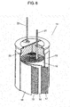
- Fig. 6 is a partially cut-away perspective view of capacitor 14 in accordance with the second exemplary embodiment of the present invention.
- Capacitor 14 of this exemplary embodiment includes, as shown in Fig. 6 , capacitor element 18 formed by winding first electrode foil 15 as an anode layer, an oxide film (not shown) formed on first electrode foil 15, and second electrode foil 17 facing the oxide film via separator 16.
- Capacitor 14 further includes a driving electrolytic solution with which separator 16 is impregnated, and case 19 for accommodating the driving electrolytic solution and capacitor element 18. Case 19 is sealed with sealing rubber 20. Furthermore, to first electrode foil 15 and second electrode foil 17, lead terminals 21 and 22 are connected, respectively. Lead terminals 21 and 22 penetrate sealing rubber 20 and extend to the outside.
- first electrode foil 15 is made of aluminum - zirconium alloy foil whose surface is etched similar to that of electrode foil 4 described in the first exemplary embodiment.
- First electrode foil 15 contains aluminum as a main component in the atomic ratio of about 99 at% or more and zirconium in the atomic ratio of at least 0.03 at% and at most 0.5 at%.
- first electrode foil 15 even in a state in which the surface thereof is not etched, includes zirconium of at least 0.03 at% and at most 0.5 at% in a region at least 10 ⁇ m deep from the surface of the foil. This is because the region at least 10 ⁇ m deep from the surface is etched by an etching process.
- an oxide film (not shown) is formed on the surface thereof by carrying out anodization after etching processing.
- first electrode foil 15 when a small amount of zirconium atoms are allowed to be contained, a crystal lattice structure in the oxide film of first electrode foil 15 is changed, thereby enabling the dielectric constant of the oxide film to be enhanced.
- capacitance of first electrode foil 15 can be remarkably enhanced.
- fine processing by etching can be carried out, and the surface area can be enlarged and the capacitance can be increased.
- the atomic ratio of zirconium atoms in first electrode foil 15 is preferably at least 0.03 at% and at most 0.5 at%.
- the increasing rate of capacitance becomes peak when the atomic ratio is at least 0.07 at% and at most 0.3 at%.
- the first and second exemplary embodiments of the present invention describe examples in which electrode foil 4 and first electrode foil 15 are subjected to etching processing, but electrode foil 4 and first electrode foil 15 may be used in a plain state in which they are not etched. Also in this case, by allowing a small amount of zirconium atoms to be contained, a crystal lattice structure of the oxide film can be changed, so that the dielectric constant can be enhanced to thus enhance the capacitance.
- first and second exemplary embodiments describe an example of a solid electrolytic capacitor or a winding type aluminum electrolytic capacitor using a conductive polymer as an electrolyte, but the present invention is not limited to these examples.
- an organic semiconductor may be used as an electrolyte for solid electrolytic capacitors, and the aluminum electrolytic capacitor may be a laminated type.
- an electrolyte in which a solid electrolyte and an electrolytic solution are combined may be used.
- electrode foil of the present invention since electrode foil of the present invention has high capacitance, it can be used for electrolytic capacitors having a small size and large capacity.
Landscapes
- Engineering & Computer Science (AREA)
- Chemical & Material Sciences (AREA)
- Materials Engineering (AREA)
- Power Engineering (AREA)
- Microelectronics & Electronic Packaging (AREA)
- Mechanical Engineering (AREA)
- Metallurgy (AREA)
- Organic Chemistry (AREA)
- Fixed Capacitors And Capacitor Manufacturing Machines (AREA)
- Electric Double-Layer Capacitors Or The Like (AREA)
Abstract
Description
- The present invention relates to electrode foil and a capacitor using the same.
- Examples of capacitors include a solid electrolytic capacitor having low ESR (equivalent series resistance) used in a periphery of a CPU (central processing unit) of a personal computer, an aluminum electrolytic capacitor used for smoothing a power supply circuit, and the like. These capacitors have been strongly demanded to have a smaller size and larger capacity.
- For example, a solid electrolytic capacitor includes electrode foil (anode foil) having an oxide film formed on the surface thereof, a solid electrolyte layer made of a conductive polymer and formed on the oxide film, and a cathode current collector formed on the solid electrolyte layer. The solid electrolyte layer and the cathode current collector form a cathode layer.
- Electrode foil can be obtained by etching metal foil such as aluminum foil. Thus, the surface area of the electrode foil can be increased and the capacitance can be enhanced.
- However, there is a technical limit to making finer by etching. Therefore, recently, use of aluminum alloy foil, which contains different metal in aluminum, as metal foil has been studied. Furthermore, it is also studied to enhance the dielectric constant of an oxide film and to increase capacity by changing a composition of metal foil itself by using aluminum alloy foil.
- Examples of the above-mentioned aluminum alloy foil include aluminum - zirconium alloy foil containing zirconium in aluminum. It is thought that, because the dielectric constant of an oxide of zirconium is high, use of the aluminum - zirconium alloy foil enhances the dielectric constant of an oxide film and thus contributes to improve the capacitance.
- In this way, conventionally, in the electrode foil made of the aluminum - zirconium alloy, the atomic ratio of zirconium is increased so as to enhance the dielectric constant of the oxide film and thereby to enhance the capacitance.
- However, in conventional electrode foil made of the aluminum - zirconium alloy, as the atomic ratio of zirconium is increased, the capacitance is rather reduced even if etching processing is carried out.
- This is because zirconium cannot be sufficiently dispersed in aluminum, and zirconium reacts with aluminum to precipitate as an intermetallic compound in electrode foil. When the electrode foil is etched, the intermetallic compound is not etched and remains in a state in which it is exposed on the surface of electrode foil. As a result, the surface area of the electrode foil cannot be sufficiently enlarged, resulting in lowering the capacitance (see, for example, Patent Literature 1).
-
- PTL 1: Japanese Patent Application Unexamined Publication No.
S60-66806 - In view of the above-mentioned problem, the present invention improves capacitance of electrode foil.
- Electrode foil includes an aluminum alloy having a composition in a region at least 10 µm deep from a surface of the foil. The composition includes aluminum as a main component and zirconium of at least 0.03 at% and at most 0.5 at%.
-
-
Fig. 1 is a perspective view of a capacitor in accordance with a first exemplary embodiment of the present invention. -
Fig. 2A is a plan view of a capacitor element used in the capacitor in accordance with the first exemplary embodiment of the present invention. -
Fig. 2B is a sectional view of the capacitor element used in the capacitor in accordance with the first exemplary embodiment of the present invention. -
Fig. 3 is a schematic sectional view of electrode foil in accordance with the first exemplary embodiment of the present invention. -
Fig. 4 is a graph showing a relation between an atomic ratio of zirconium and an increasing rate of capacitance in the electrode foil in accordance with the first exemplary embodiment of the present invention. -
Fig. 5 is a graph showing a relation between presence or absence of heat treatment and a leak current in the electrode foil in accordance with the first exemplary embodiment of the present invention. -
Fig. 6 is a partially cut-away perspective view of a capacitor in accordance with a second exemplary embodiment of the present invention. - Electrode foil in accordance with a first exemplary embodiment of the present invention and a capacitor using the electrode foil are described with reference to drawings. The capacitor of this exemplary embodiment is a solid electrolytic capacitor using a conductive polymer material as an electrolyte.
-
Fig. 1 is a perspective view of a capacitor in accordance with the first exemplary embodiment of the present invention.Fig. 2A is a plan view of a capacitor element used in the capacitor in accordance with the first exemplary embodiment of the present invention, andFig. 2B is a sectional view of the capacitor element.Fig. 2B shows a shape of a cross section taken alongline 2B-2B inFig. 2A . - As shown in
Fig. 1 ,capacitor 2 is configured by laminating a plurality ofcapacitor elements 1 each having a plate shape. - Furthermore, as shown in
Fig. 2A ,capacitor element 1 includesanode layer 5,cathode layer 7, and resist portion 6 (electrical insulator) for separating betweenanode layer 5 andcathode layer 7. - Furthermore, as shown in
Fig. 2B ,capacitor element 1 includeselectrode foil 4. On the surface ofelectrode foil 4,oxide film 3 is formed. -
Resist portion 6 is provided such thatelectrode foil 4 is pressed afteroxide film 3 is formed on the surface ofelectrode foil 4.Resist portion 6 divideselectrode foil 4 intoanode layer 5 and a cathode formation part includingcathode layer 7. -
Cathode layer 7 is formed onoxide film 3 of the cathode formation part.Cathode layer 7 includessolid electrolyte layer 8 made of a conductive polymer formed onoxide film 3, and cathodecurrent collector 9 made of a carbon layer and a silver paste layer formed onsolid electrolyte layer 8. - As shown in
Fig. 1 ,anode layer 5 of each of the plurality of laminatedcapacitor elements 1 is connected toanode COM terminal 10 by laser welding. - Cathode
COM terminal 11 is connected tocathode layers 7. Cathode COMterminal 11 is provided withbent portion 11a.Bent portion 11a is formed by upwardly bending the both side surfaces of a portion on whichcapacitor elements 1 are placed. The portion ofcathode COM terminal 11 on which the elements are mounted andcathode layer 7 ofcapacitor element 1,bent portion 11a andcathode layer 7, as well ascathode layers 7 ofcapacitor elements 1 can be joined with each other with an electric conductive adhesive agent, respectively. - Anode
COM terminal 10 andcathode COM terminal 11 together with a plurality ofcapacitor elements 1 are integrally covered withcoating resin body 12 made of an insulating resin in a state in which a part of each ofanode COM terminal 10 andcathode COM terminal 11 is exposed to the outer surface. The part of each ofanode COM terminal 10 andcathode COM terminal 11 expressing fromcoating resin body 12 is bent toward the bottom surface alongcoating resin body 12. Thus, surfacemount type capacitor 2 provided on the bottom surface with an anode terminal and a cathode terminal can be produced. -
Fig. 3 is a schematic sectional view ofelectrode foil 4 in accordance with the first exemplary embodiment of the present invention. As shown inFig. 3 , the surface ofelectrode foil 4 is etched so as to form fine pits 13. In order to increase capacitance,electrode foil 4 having a thickness of 70 to 120 µm is usually etched to the depth of about 30 to 35 µm. Whenelectrode foil 4 is etched to the depth of at least 10 µm or more, sufficient capacitance can be ensured. - In etching of
electrode foil 4, as an etchant, a mixed solution obtained by mixing sulfuric acid as additives into an acidic aqueous solution having a chlorine ion concentration of 2.75 N so that the sulfuric acid concentration is 0.1% is used. In the etching, a plain (non-etched)state electrode foil 4 is impregnated with the etchant. - An etching process is carried out by setting one carbon electrode each on both sides of
electrode foil 4, and applying an alternating current to the two carbon electrodes. At this time, an AC power supply condition is adjusted so that etching reduction amount per unit area ofelectrode foil 4 is 10 mg/cm2. After that, dechlorination and drying are carried out so as to produce etchedelectrode foil 4. - As shown in
Fig. 3 , on etchedelectrode foil 4,oxide film 3 is formed along the shape offine pits 13 formed on the surface ofelectrode foil 4.Oxide film 3 is formed by anodizingelectrode foil 4. The film thickness ofoxide film 3 in this exemplary embodiment is about 0.01 µm. - In anodization of
electrode foil 4, etchedelectrode foil 4 is anodized under conditions of an anodization voltage of 4.5 V, and a retention time of 20 minutes, with 0.3% ammonium phosphate aqueous solution at 70°C at 0.05 A/cm2. The capacitance of the electrode foil is measured under conditions in which 8% ammonium pentaborate aqueous solution is used, the measurement temperature is 30°C, the measurement area is 10 cm2, the measurement frequency is 120 Hz, and an impedance analyzer or an LCR meter are used. -
Electrode foil 4 of this exemplary embodiment is made of an aluminum - zirconium alloy containing aluminum as a main component. The atomic ratio of zirconium inelectrode foil 4 is about 0.03 atomic percent (at%) or more and 0.5 at% or less, and the atomic ratio of aluminum is about 99 at% or more. -
Electrode foil 4 includes inevitable impurities, including 64 ppm of silicon, 18 ppm of iron, 4 ppm of copper, nickel, and the like, in mass fraction, and other compositions in the mass fraction or less. These impurities are smaller than zirconium in terms of the mass fraction and the atomic ratio. That is to say, in the atomic ratio ofelectrode foil 4 in this exemplary embodiment, zirconium is the second largest to aluminum. -
Electrode foil 4 includes a plurality of intermetallic compounds any of which has a diameter of 1 µm or less. The composition of the intermetallic compound is Al3Zr. -
Fig. 4 is a graph showing an increasing rate of capacitance ofelectrode foil 4 in this exemplary embodiment in comparison with that of conventional electrode foil using aluminum foil. In the electrode foil made of aluminum foil as the comparative example, an atomic ratio of zirconium is less than 0.01 at% and an atomic ratio of aluminum is 99.9 at% or more. Bothelectrode foil 4 of this exemplary embodiment and the electrode foil of the comparative example are subjected to anodization after etching as mentioned above. -
Fig. 4 shows an increasing rate (%) of capacitance in the axis of ordinate, and shows that a reference value (0%) is the same value as the capacitance of the comparative example. Furthermore, the axis of abscissa ofFig. 4 shows the atomic ratio (at%) of zirconium inelectrode foil 4. Note here that an actually measured value of the capacitance in the reference value (0%) is about 700 µF when electrode foil having a size of 1 cm × 2 cm is used. - As is apparent from the results of
Fig. 4 , when the atomic ratio of zirconium is in the range of 0.07 at% or more and 0.3 at% or less, the capacitance is increased by substantially 100% as compared with the comparative example and the increasing rate is a peak. - Also when the atomic ratio of zirconium is 0.03 at% or more and less than 0.07 at%, and more than 0.3 at% and 0.5 at% or less, the capacitance of
electrode foil 4 is increased as compared with the comparative example. - Furthermore, as a result of analysis by SEM photography, when the atomic ratio of zirconium is in the range of 0.3 at% or less, intermetallic compounds hardly precipitate, and slightly precipitating intermetallic compounds are very small and have a diameter of 1 µm or less.
- However, when the atomic ratio of zirconium is more than 0.5 at%, large intermetallic compounds having a diameter of 20 µm or more precipitate, and the diameter and the number thereof are increased as the atomic ratio increases. The intermetallic compounds are not etched and remain on the surface of
electrode foil 4, which remarkably reduces the capacitance. For example, inFig. 4 , when the atomic ratio of zirconium is 0.9%, a large number of intermetallic compounds start to precipitate, and the capacitance is lowered as compared with the conventional example. When the atomic ratio of zirconium is 2%, the capacitance is lowered by as large as 80% as compared with the conventional example. - When zirconium is in the range of 0.3 at% or more and 0.5 at% or less, intermetallic compounds having a diameter of larger than 1 µm also precipitate, but the size of the intermetallic compound is relatively smaller and the number thereof is smaller as compared with the case where the atomic ratio is more than 0.5 at%.
- As mentioned above, in
capacitor element 1 in this exemplary embodiment, the capacitance ofelectrode foil 4 can be increased. This is because the precipitation of the intermetallic compounds can be suppressed by reducing the content of zirconium as mentioned above. Therefore, according to this exemplary embodiment,electrode foil 4 can be finely etched, and the surface area can be enlarged and the capacitance can be increased. - Furthermore, in this exemplary embodiment, even though the content of zirconium is reduced to the above-mentioned range, the dielectric constant of
oxide film 3 can be remarkably increased, and the capacitance can be increased. - According to the study, it is thought to be because the dielectric constant is increased largely due to the dielectric constant derived from oxides other than an oxide of zirconium (ZrO2). That is to say, it is thought that a part of aluminum in a crystal lattice of alumina (oxide film 3) is easily subjected with zirconium during anodization, for example, because of the atomic size of zirconium, and because properties with respect to pH and electric potential are similar in zirconium and aluminum. Thus, it is assumed that the crystalline structure in the vicinity of zirconium is changed and a crystal lattice including Al2-xZrxO3+y is formed, resulting in that the dielectric constant is remarkably increased.
- In this exemplary embodiment,
electrode foil 4 is etched. It is preferable that etchedelectrode foil 4 has a composition including an aluminum alloy containing aluminum as a main component and zirconium of at least 0.03 at% and at most 0.5 at%. Furthermore, sinceelectrode foil 4 in the depth of at least 10 µm is etched, it is preferable thatelectrode foil 4, even in a state before it is etched, is made of an aluminum alloy containing aluminum as a main component and zirconium of at least 0.03 at% and at most 0.5 at% in the region at least 10 µm deep from the surface of the foil. - As mentioned above, according to the present invention, the surface area can be enlarged by etching, and
oxide film 3 having high dielectric constant can be formed. Thus, as a result, by using foil made of the aluminum - zirconium alloy, the capacitance ofelectrode foil 4 can be remarkably improved. - Note here that
electrode foil 4 can have a reduced LC (Leak Current) value when heat treatment is carried out before etching. -
Fig. 5 is a graph showing measurement results of the LC values inelectrode foil 4 that has not been subjected to heat treatment andelectrode foil 4 that has been subjected to heat treatment in an nitrogen atmosphere at 350°C for 8 hours, followed by carrying out an etching process and an anodizing process, respectively. In both cases, the ratio of zirconium inelectrode foil 4 is in the range from 0.03 to 0.5 at%. - The LC value is measured in 15% diammonium adipate aqueous solution at 30°C by using
electrode foil 4 having a shape of 1 cm × 2 cm in each sample. The LC value is a value of electric current when stainless steel foil having a sufficiently large area is used for a cathode, each sample is used for an anode, and a DC voltage of 3.5 V is applied for two minutes. - As a result, as shown in
Fig. 5 , when zirconium is in the range from 0.03 to 0.5 at%, a leak current can be reduced by 10 µA or more inelectrode foil 4 that has been subjected to heat treatment as compared with a case where heat treatment has not been carried out. - Furthermore, also in the case where the heat treatment is carried out for 2 hours or 20 hours, in
electrode foil 4 that has been subjected to heat treatment, a leak current can be reduced similar to the example mentioned above. Also in the case where the heat treatment temperature is 250°C or 450°C and heat treatment time is 8 hours, inelectrode foil 4 that has been subjected to heat treatment, a leak current can be reduced as in the example mentioned above. - In a second exemplary embodiment,
electrode foil 4 that is similar to that described in the first exemplary embodiment is used in an aluminum electrolytic capacitor (capacitor 14) using a liquid electrolytic solution as an electrolyte is described.Fig. 6 is a partially cut-away perspective view ofcapacitor 14 in accordance with the second exemplary embodiment of the present invention. -
Capacitor 14 of this exemplary embodiment includes, as shown inFig. 6 ,capacitor element 18 formed by windingfirst electrode foil 15 as an anode layer, an oxide film (not shown) formed onfirst electrode foil 15, andsecond electrode foil 17 facing the oxide film viaseparator 16. -
Capacitor 14 further includes a driving electrolytic solution with whichseparator 16 is impregnated, andcase 19 for accommodating the driving electrolytic solution andcapacitor element 18.Case 19 is sealed with sealingrubber 20. Furthermore, tofirst electrode foil 15 andsecond electrode foil 17,lead terminals terminals rubber 20 and extend to the outside. - In this exemplary embodiment,
first electrode foil 15 is made of aluminum - zirconium alloy foil whose surface is etched similar to that ofelectrode foil 4 described in the first exemplary embodiment.First electrode foil 15 contains aluminum as a main component in the atomic ratio of about 99 at% or more and zirconium in the atomic ratio of at least 0.03 at% and at most 0.5 at%. - It is preferable that
first electrode foil 15, even in a state in which the surface thereof is not etched, includes zirconium of at least 0.03 at% and at most 0.5 at% in a region at least 10 µm deep from the surface of the foil. This is because the region at least 10 µm deep from the surface is etched by an etching process. In addition, infirst electrode foil 15, as in the first exemplary embodiment, an oxide film (not shown) is formed on the surface thereof by carrying out anodization after etching processing. - Also in this exemplary embodiment, when a small amount of zirconium atoms are allowed to be contained, a crystal lattice structure in the oxide film of
first electrode foil 15 is changed, thereby enabling the dielectric constant of the oxide film to be enhanced. Thus, capacitance offirst electrode foil 15 can be remarkably enhanced. Furthermore, by suppressing the atomic ratio of zirconium atoms, fine processing by etching can be carried out, and the surface area can be enlarged and the capacitance can be increased. - Also in this exemplary embodiment, in order to increase the capacitance, the atomic ratio of zirconium atoms in
first electrode foil 15 is preferably at least 0.03 at% and at most 0.5 at%. The increasing rate of capacitance becomes peak when the atomic ratio is at least 0.07 at% and at most 0.3 at%. - The first and second exemplary embodiments of the present invention describe examples in which
electrode foil 4 andfirst electrode foil 15 are subjected to etching processing, butelectrode foil 4 andfirst electrode foil 15 may be used in a plain state in which they are not etched. Also in this case, by allowing a small amount of zirconium atoms to be contained, a crystal lattice structure of the oxide film can be changed, so that the dielectric constant can be enhanced to thus enhance the capacitance. - Furthermore, the first and second exemplary embodiments describe an example of a solid electrolytic capacitor or a winding type aluminum electrolytic capacitor using a conductive polymer as an electrolyte, but the present invention is not limited to these examples. For example, an organic semiconductor may be used as an electrolyte for solid electrolytic capacitors, and the aluminum electrolytic capacitor may be a laminated type. Furthermore, an electrolyte in which a solid electrolyte and an electrolytic solution are combined may be used.
- As mentioned above, since electrode foil of the present invention has high capacitance, it can be used for electrolytic capacitors having a small size and large capacity.
-
- 1, 18 capacitor element
- 2, 14 capacitor
- 3 oxide film
- 4 electrode foil
- 5 anode layer
- 6 resist portion
- 7 cathode layer
- 8 solid electrolyte layer
- 9 cathode current collector
- 10 anode COM terminal
- 11 cathode COM terminal
- 11a bent portion
- 12 coating resin body
- 13 pit
- 15 first electrode foil
- 16 separator
- 17 second electrode foil
- 19 case
- 20 sealing rubber
- 21, 22 lead terminal
Claims (8)
- Electrode foil comprising an aluminum alloy having a composition in a region at least 10 µm deep from a surface of the foil, the composition including aluminum as a main component and zirconium of at least 0.03 atomic percent (at %) and at most 0.5 at%.
- The electrode foil of claim 1, wherein the electrode foil is formed of an aluminum alloy in a whole range, and the aluminum alloy including aluminum as a main component and zirconium of at least 0.03 at% and at most 0.5 at%, and the surface is etched.
- The electrode foil of claim 1,
wherein in an atomic ratio of components contained, zirconium is second largest to aluminum. - The electrode foil of claim 1, comprising an intermetallic compound including Al3Zr,
wherein the intermetallic compound has a diameter of 1 µm or less. - A capacitor comprising a capacitor element including:electrode foil of claim 1;an oxide film formed on a surface of the electrode foil; anda cathode layer including a solid electrolyte layer and a cathode current collector, and formed on the oxide film.
- The capacitor of claim 5,
wherein the electrode foil is formed of an aluminum alloy in a whole range of the foil, and the aluminum alloy including aluminum as a main component and zirconium of at least 0.03 at% and at most 0.5 at%, and the surface is etched. - A capacitor comprising:a capacitor element including
electrode foil of claim 1,
an oxide film formed on the electrode foil, and
second electrode foil facing the oxide film via a separator;a driving electrolytic solution with which the separator is impregnated; anda case for accommodating the driving electrolytic solution and the capacitor element. - The capacitor of claim 7,
wherein the electrode foil is formed of an aluminum alloy in a whole range of the foil, and aluminum alloy including aluminum as a main component and zirconium of at least 0.03 at% and at most 0.5 at%, and wherein the surface is etched.
Applications Claiming Priority (2)
| Application Number | Priority Date | Filing Date | Title |
|---|---|---|---|
| JP2009249769 | 2009-10-30 | ||
| PCT/JP2010/006174 WO2011052156A1 (en) | 2009-10-30 | 2010-10-19 | Electrode foil and capacitor using same |
Publications (1)
| Publication Number | Publication Date |
|---|---|
| EP2495344A1 true EP2495344A1 (en) | 2012-09-05 |
Family
ID=43921593
Family Applications (1)
| Application Number | Title | Priority Date | Filing Date |
|---|---|---|---|
| EP10826293A Withdrawn EP2495344A1 (en) | 2009-10-30 | 2010-10-19 | Electrode foil and capacitor using same |
Country Status (5)
| Country | Link |
|---|---|
| US (1) | US8749954B2 (en) |
| EP (1) | EP2495344A1 (en) |
| JP (1) | JP5786140B2 (en) |
| CN (1) | CN102597286B (en) |
| WO (1) | WO2011052156A1 (en) |
Families Citing this family (4)
| Publication number | Priority date | Publication date | Assignee | Title |
|---|---|---|---|---|
| JP2013214727A (en) * | 2012-03-07 | 2013-10-17 | Panasonic Corp | Electrode foil and capacitor using the same |
| WO2017014020A1 (en) * | 2015-07-23 | 2017-01-26 | 株式会社村田製作所 | Capacitor and method for manufacturing same |
| WO2019194092A1 (en) * | 2018-04-02 | 2019-10-10 | 日本ケミコン株式会社 | Electrolytic capacitor |
| WO2021192607A1 (en) * | 2020-03-27 | 2021-09-30 | パナソニックIpマネジメント株式会社 | Electrode foil for electrolytic capacitor, electrolytic capacitor, and method for manufacturing electrolytic capacitor |
Family Cites Families (21)
| Publication number | Priority date | Publication date | Assignee | Title |
|---|---|---|---|---|
| JPS59123152A (en) * | 1982-12-28 | 1984-07-16 | Hajime Ishimaru | Ion pump |
| JPS6066806A (en) | 1983-09-22 | 1985-04-17 | ニチコン株式会社 | Aluminum alloy electrode for electrolytic condenser |
| JPH0828312B2 (en) * | 1987-11-09 | 1996-03-21 | ニチコン株式会社 | Aluminum alloy electrode for electrolytic capacitors |
| JPH0722093B2 (en) * | 1988-05-18 | 1995-03-08 | 新日本製鐵株式会社 | Electrode capacitor electrode material and manufacturing method thereof |
| JPH03276620A (en) | 1990-03-26 | 1991-12-06 | Matsushita Electric Ind Co Ltd | Solid-state electrolytic capacitor |
| JPH03276619A (en) | 1990-03-26 | 1991-12-06 | Matsushita Electric Ind Co Ltd | solid electrolytic capacitor |
| JP2960117B2 (en) | 1990-06-25 | 1999-10-06 | 昭和アルミニウム株式会社 | Aluminum foil for electrolytic capacitor electrodes |
| JP2690415B2 (en) | 1991-01-26 | 1997-12-10 | 政志 船山 | Pyrogenic substance adsorbent and method for quantifying exothermic substance using the same |
| JPH06264201A (en) * | 1993-03-15 | 1994-09-20 | Nippon Steel Corp | Method for manufacturing electrode material for electrolytic capacitors |
| JPH06267803A (en) | 1993-03-16 | 1994-09-22 | Nippon Steel Corp | Electrode material for capacitors |
| JP3293241B2 (en) | 1993-05-20 | 2002-06-17 | 三菱アルミニウム株式会社 | Aluminum foil material for electrodes of electrolytic capacitors with excellent surface area expansion effect |
| JP3148515B2 (en) * | 1994-05-30 | 2001-03-19 | 松下電器産業株式会社 | Liquid crystal display and electronic components |
| JPH08130163A (en) | 1994-10-28 | 1996-05-21 | Japan Carlit Co Ltd:The | Method for manufacturing solid electrolytic capacitor |
| JPH09266141A (en) | 1996-03-27 | 1997-10-07 | Japan Carlit Co Ltd:The | Method for manufacturing solid electrolytic capacitor |
| JP2000012402A (en) | 1998-06-19 | 2000-01-14 | Nichicon Corp | Electrode foil for aluminium electrolytic capacitor |
| JP3689323B2 (en) * | 2000-09-20 | 2005-08-31 | 昭和電工株式会社 | Aluminum material for electrolytic capacitor electrodes |
| WO2005022568A1 (en) | 2003-08-27 | 2005-03-10 | Showa Denko K.K. | Sheet for capacitor electrodes, method and apparatus for manufacturing the same, and electrolytic acpacitors |
| JP2005072462A (en) | 2003-08-27 | 2005-03-17 | Showa Denko Kk | Capacitor electrode sheet, its manufacturing method, manufacturing apparatus, and electrolytic capacitor |
| KR101224064B1 (en) | 2005-11-10 | 2013-01-18 | 도요 알루미늄 가부시키가이샤 | Electrode structure, capacitor and method for producing electrode structure |
| JP5160839B2 (en) * | 2006-08-29 | 2013-03-13 | 東洋アルミニウム株式会社 | Aluminum alloy foil for current collector |
| JP5160849B2 (en) * | 2007-09-27 | 2013-03-13 | 東洋アルミニウム株式会社 | Aluminum alloy foil for current collector |
-
2010
- 2010-10-19 JP JP2011538232A patent/JP5786140B2/en not_active Expired - Fee Related
- 2010-10-19 CN CN201080048795.3A patent/CN102597286B/en not_active Expired - Fee Related
- 2010-10-19 WO PCT/JP2010/006174 patent/WO2011052156A1/en not_active Ceased
- 2010-10-19 US US13/500,096 patent/US8749954B2/en not_active Expired - Fee Related
- 2010-10-19 EP EP10826293A patent/EP2495344A1/en not_active Withdrawn
Non-Patent Citations (1)
| Title |
|---|
| See references of WO2011052156A1 * |
Also Published As
| Publication number | Publication date |
|---|---|
| CN102597286B (en) | 2014-10-15 |
| US20120200985A1 (en) | 2012-08-09 |
| WO2011052156A1 (en) | 2011-05-05 |
| CN102597286A (en) | 2012-07-18 |
| JP5786140B2 (en) | 2015-09-30 |
| JPWO2011052156A1 (en) | 2013-03-14 |
| US8749954B2 (en) | 2014-06-10 |
Similar Documents
| Publication | Publication Date | Title |
|---|---|---|
| JP4275187B2 (en) | Electrolytic capacitor | |
| JP4274857B2 (en) | Electrolytic capacitor manufacturing method | |
| US8749954B2 (en) | Electrode foil and capacitor using same | |
| US20250087426A1 (en) | Capacitor, electric circuit, circuit board, apparatus, and method for manufacturing capacitor | |
| KR20060125747A (en) | Solid electrolytic capacitors | |
| US8654509B2 (en) | Electrode foil, process for producing same, and capacitor using electrode foil | |
| US20260081081A1 (en) | Capacitor, electric circuit, circuit board, and apparatus | |
| JP2010212594A (en) | Solid electrolytic capacitor and its manufacturing method | |
| US20100053848A1 (en) | Niobium solid electrolytic capacitor | |
| WO2013114759A1 (en) | Solid electrolytic capacitor and method for producing same | |
| CN109791843B (en) | Electrode foil and electrolytic capacitor | |
| US20060250752A1 (en) | Method and apparatus for electrically isolating capacitor electrodes using separator | |
| JP4454526B2 (en) | Solid electrolytic capacitor and manufacturing method thereof | |
| JP2008172185A (en) | Electrolytic capacitor | |
| JP2008022041A (en) | Electrolytic capacitor | |
| JP4947888B2 (en) | Manufacturing method of solid electrolytic capacitor | |
| JP2006108172A (en) | Electrolytic capacitor and manufacturing method therefor | |
| JP4867462B2 (en) | Aluminum electrolytic capacitor and cathode foil for aluminum electrolytic capacitor | |
| JP4942837B2 (en) | Solid electrolytic capacitor | |
| JPH0533000Y2 (en) | ||
| WO2011145372A1 (en) | Method of manufacturing capacitor | |
| WO2025238903A1 (en) | Multilayer body, capacitor, electrical circuit, circuit board, apparatus, and multilayer body manufacturing method | |
| Franklin | Electrolytic capacitors | |
| KR20110097223A (en) | Manufacturing method of aluminum thin film with composite oxide dielectric by cathode electroplating and anodization | |
| JPH02166714A (en) | Manufacture of solid electrolytic capacitor |
Legal Events
| Date | Code | Title | Description |
|---|---|---|---|
| PUAI | Public reference made under article 153(3) epc to a published international application that has entered the european phase |
Free format text: ORIGINAL CODE: 0009012 |
|
| 17P | Request for examination filed |
Effective date: 20120430 |
|
| AK | Designated contracting states |
Kind code of ref document: A1 Designated state(s): AL AT BE BG CH CY CZ DE DK EE ES FI FR GB GR HR HU IE IS IT LI LT LU LV MC MK MT NL NO PL PT RO RS SE SI SK SM TR |
|
| DAX | Request for extension of the european patent (deleted) | ||
| RAP1 | Party data changed (applicant data changed or rights of an application transferred) |
Owner name: PANASONIC INTELLECTUAL PROPERTY MANAGEMENT CO., LT |
|
| RAP1 | Party data changed (applicant data changed or rights of an application transferred) |
Owner name: PANASONIC INTELLECTUAL PROPERTY MANAGEMENT CO., LT |
|
| STAA | Information on the status of an ep patent application or granted ep patent |
Free format text: STATUS: THE APPLICATION HAS BEEN WITHDRAWN |
|
| 18W | Application withdrawn |
Effective date: 20150114 |
|
| R18W | Application withdrawn (corrected) |
Effective date: 20160114 |