EP2495134A1 - Power supply circuit - Google Patents
Power supply circuit Download PDFInfo
- Publication number
- EP2495134A1 EP2495134A1 EP10826741A EP10826741A EP2495134A1 EP 2495134 A1 EP2495134 A1 EP 2495134A1 EP 10826741 A EP10826741 A EP 10826741A EP 10826741 A EP10826741 A EP 10826741A EP 2495134 A1 EP2495134 A1 EP 2495134A1
- Authority
- EP
- European Patent Office
- Prior art keywords
- relay
- voltage battery
- battery
- inverter
- power
- Prior art date
- Legal status (The legal status is an assumption and is not a legal conclusion. Google has not performed a legal analysis and makes no representation as to the accuracy of the status listed.)
- Granted
Links
Images
Classifications
-
- B—PERFORMING OPERATIONS; TRANSPORTING
- B60—VEHICLES IN GENERAL
- B60L—PROPULSION OF ELECTRICALLY-PROPELLED VEHICLES; SUPPLYING ELECTRIC POWER FOR AUXILIARY EQUIPMENT OF ELECTRICALLY-PROPELLED VEHICLES; ELECTRODYNAMIC BRAKE SYSTEMS FOR VEHICLES IN GENERAL; MAGNETIC SUSPENSION OR LEVITATION FOR VEHICLES; MONITORING OPERATING VARIABLES OF ELECTRICALLY-PROPELLED VEHICLES; ELECTRIC SAFETY DEVICES FOR ELECTRICALLY-PROPELLED VEHICLES
- B60L50/00—Electric propulsion with power supplied within the vehicle
- B60L50/50—Electric propulsion with power supplied within the vehicle using propulsion power supplied by batteries or fuel cells
-
- B—PERFORMING OPERATIONS; TRANSPORTING
- B60—VEHICLES IN GENERAL
- B60L—PROPULSION OF ELECTRICALLY-PROPELLED VEHICLES; SUPPLYING ELECTRIC POWER FOR AUXILIARY EQUIPMENT OF ELECTRICALLY-PROPELLED VEHICLES; ELECTRODYNAMIC BRAKE SYSTEMS FOR VEHICLES IN GENERAL; MAGNETIC SUSPENSION OR LEVITATION FOR VEHICLES; MONITORING OPERATING VARIABLES OF ELECTRICALLY-PROPELLED VEHICLES; ELECTRIC SAFETY DEVICES FOR ELECTRICALLY-PROPELLED VEHICLES
- B60L3/00—Electric devices on electrically-propelled vehicles for safety purposes; Monitoring operating variables, e.g. speed, deceleration or energy consumption
-
- B—PERFORMING OPERATIONS; TRANSPORTING
- B60—VEHICLES IN GENERAL
- B60L—PROPULSION OF ELECTRICALLY-PROPELLED VEHICLES; SUPPLYING ELECTRIC POWER FOR AUXILIARY EQUIPMENT OF ELECTRICALLY-PROPELLED VEHICLES; ELECTRODYNAMIC BRAKE SYSTEMS FOR VEHICLES IN GENERAL; MAGNETIC SUSPENSION OR LEVITATION FOR VEHICLES; MONITORING OPERATING VARIABLES OF ELECTRICALLY-PROPELLED VEHICLES; ELECTRIC SAFETY DEVICES FOR ELECTRICALLY-PROPELLED VEHICLES
- B60L3/00—Electric devices on electrically-propelled vehicles for safety purposes; Monitoring operating variables, e.g. speed, deceleration or energy consumption
- B60L3/04—Cutting off the power supply under fault conditions
-
- B—PERFORMING OPERATIONS; TRANSPORTING
- B60—VEHICLES IN GENERAL
- B60L—PROPULSION OF ELECTRICALLY-PROPELLED VEHICLES; SUPPLYING ELECTRIC POWER FOR AUXILIARY EQUIPMENT OF ELECTRICALLY-PROPELLED VEHICLES; ELECTRODYNAMIC BRAKE SYSTEMS FOR VEHICLES IN GENERAL; MAGNETIC SUSPENSION OR LEVITATION FOR VEHICLES; MONITORING OPERATING VARIABLES OF ELECTRICALLY-PROPELLED VEHICLES; ELECTRIC SAFETY DEVICES FOR ELECTRICALLY-PROPELLED VEHICLES
- B60L50/00—Electric propulsion with power supplied within the vehicle
- B60L50/50—Electric propulsion with power supplied within the vehicle using propulsion power supplied by batteries or fuel cells
- B60L50/60—Electric propulsion with power supplied within the vehicle using propulsion power supplied by batteries or fuel cells using power supplied by batteries
-
- Y—GENERAL TAGGING OF NEW TECHNOLOGICAL DEVELOPMENTS; GENERAL TAGGING OF CROSS-SECTIONAL TECHNOLOGIES SPANNING OVER SEVERAL SECTIONS OF THE IPC; TECHNICAL SUBJECTS COVERED BY FORMER USPC CROSS-REFERENCE ART COLLECTIONS [XRACs] AND DIGESTS
- Y02—TECHNOLOGIES OR APPLICATIONS FOR MITIGATION OR ADAPTATION AGAINST CLIMATE CHANGE
- Y02T—CLIMATE CHANGE MITIGATION TECHNOLOGIES RELATED TO TRANSPORTATION
- Y02T10/00—Road transport of goods or passengers
- Y02T10/60—Other road transportation technologies with climate change mitigation effect
- Y02T10/70—Energy storage systems for electromobility, e.g. batteries
Definitions
- the present invention relates to a power supply circuit, for example, a power supply circuit including a blocking member that is detachably provided on a power supply path from a battery to a load.
- hybrid cars driven by using both an engine and an electric motor have become widespread.
- a high-voltage battery whose voltage is higher than that of a low-voltage battery for starting-up the engine is mounted, and a direct current supplied from the high-voltage battery is inverted to an alternating current by an inverter and then is supplied to the electric motor.
- a flow of current between the inverter and the high-voltage battery is blocked in advance in order to allow maintenance to be performed safely. Therefore, there is disclosed a power supply circuit in which a service plug (blocking member), which is manually detachable, is interposed between the inverter and the high-voltage battery, and the service plug is detached by a worker at the time of the maintenance to block the flow of current between the inverter and the high-voltage battery (for example, PTL 1).
- a service plug blocking member
- Fig. 2 shows an example of the above-described power supply circuit.
- the power supply circuit 100 includes a battery pack 101 disposed at the rear of the vehicle, an inverter 102 and a motor 103 that are disposed at the front of the vehicle as a load, an ECU 104 that is disposed at the front of the vehicle as a relay control unit that controls an operation of the inverter 102 and the motor 103.
- a high-voltage battery 105 is built in the battery pack 101, and a direct current supplied from the high-voltage-battery 105 is converted to an alternating current power source by the inverter 102 and is supplied to the motor 103.
- relays 106 provided between the high-voltage battery 105 and the inverter 102 are built in the battery pack 101. Both ends of a relay coil C provided to each of the relays 106 are connected to the ECU 104. The ECU 104 controls the current passing through the relay coil C and thereby controls the turning on and off of a contact point S of each of the relays 106.
- the high-voltage battery 105 is an assembled battery in which batteries of a plurality of batteries are connected to each other in series, and a service plug 107 is provided between the batteries.
- the service plug 107 is detachably provided between the batteries making up the high-voltage battery 105.
- the service plug 107 is provided with an interlock switch 108 that detects the attachment and detachment of the service plug 107.
- the interlock switch 108 is turned off when the service plug 107 is detached, and is turned on when the service plug 107 is attached.
- the ECU 104 is connected to the interlock switch 108 with the inverter 102 and the motor 103 interposed therebetween, determines that the service plug 107 is detached when the interlock switch 108 is turned off, and blocks the current flowing through the relay coil C and turns off the relay 106. Therefore, it is possible to more reliably block the supply of power from the high-voltage battery 105 to the inverter 102 and the motor 103.
- an object of the invention is to provide a power supply circuit in which the number of electric wires is reduced and thereby cost reduction is realized.
- the invention for solving the above-described problems provides a power supply circuit: including a battery; a load to which power is supplied from the battery; a relay that is provided between the battery and the load; a relay control unit to which both ends of a relay coil provided in the relay are connected, and that controls current flowing through the relay coil by controlling a turning on and off of the relay; a blocking member that is detachably provided on a power supply path from the battery to the load, wherein when the blocking member is detached, the supply of power from the battery to the load is blocked and when the blocking member is attached, the supply of power from the battery to the load is enabled; and an interlock switch that is turned off when the blocking member is detached and is turned on when the blocking member is attached, wherein the interlock switch is connected between the relay control unit and the relay coil.
- a plurality of the relays are provided, other ends of relay coils provided in the plurality of relays are collectively connected to each other and are connected to one ground terminal provided on the relay control unit, and the interlock switch is connected between the ground terminal of the relay control unit and a downstream side in relation to a connection point at which the other ends of the relay coils are collectively connected.
- the interlock switch is connected between the relay control unit and the relay coils, such that when the interlock switch is turned off, the flow of current to the relay coils is blocked and thereby the relays are turned off. Therefore, two electric wires connecting the relay control unit and the interlock switch can be detached while allowing the relays to be turned off when the interlock switch is turned off, whereby cost reduction can be realized.
- the interlock switch is connected between the ground terminal of the relay control unit and the downstream side in relation to the connection point at which the other ends of the relay coils are collectively connected, such that the plurality of relays can be turned off by the single interlock switch and thereby it is not necessary to provide the interlock switch for every relay, accordingly, cost reduction can be realized.
- the power supply circuit 1 includes a battery pack 2 disposed at the rear of a vehicle, an inverter 3 and a motor 4, which are disposed at the front of the vehicle, as a load, an ECU 5, which is disposed at the front of the vehicle, as a relay control unit, a service plug 6 as a blocking member, and an interlock switch 7.
- a high-voltage battery 21 as a battery, and three relays 22a to 22c provided at both ends of the high-voltage battery 21 are built in the battery pack 2.
- the high-voltage battery 21 has a high voltage by connecting, for example, six batteries in series.
- Contact points S of the relays 22a and 22b are connected between both ends of the high-voltage battery 21 and the inverter 3, respectively.
- a contact point S of the relay 22c and a current restriction resistor R for restricting a rush current are connected in parallel with the relay 22b.
- the relay 22b is connected to a negative side of the high-voltage battery 21.
- the turning on and off of the above-described relays 22a to 22c is controlled by the ECU 5.
- the ECU 5 turns on the relays 22a to 22c according to a turning on of the ignition switch, for example, and begins to start the supply of power to the inverter 3 and the motor 4 from the high-current battery 21.
- the ECU 5 first, turns on the relays 22a and 22c and supplies power via the current restriction resistor R, and then turns on the relay 22b. Due to the current restriction resistor R, the rush current flowing from the high-voltage battery 21 to the inverter 3 is restricted.
- the inverter 3 is provided at a downstream side of the relays 22a to 22c, is operated by the supply of power from the high-voltage battery 21, and converts a direct current from the high-voltage battery 21 to an alternating current.
- the motor 4 is provided at a downstream side of the inverter 3 and is operated by the supply of power from the high-voltage battery 21, which is converted to the alternating current by the inverter 3.
- both ends of each of the relay coils C provided in the relays 22a to 22c are connected to the ECU 5, and the ECU 5 controls the current flowing through the relay coils C and thereby controls the turning on and off of the relays 22a to 22c.
- the ECU 5 includes the same number of signal terminals T + as the number of the relays 22a to 22c, to which one end of each of the three relay coils C is connected, respectively, and a ground terminal T - to which other ends of the relay coils C are collectively connected.
- the ground terminal T - is grounded.
- the ECU 5 controls an output of each of the signal terminals T + and thereby controls the current flowing through the relay coils C.
- the ECU 5 is connected to a power switch SW that is built in the inverter 3 or motor 4 and thereby controls the turning on and off of the power switch SW.
- the service plug 6 is formed of a fusible conductive member that is melted down when an overcurrent flows therethrough.
- the service plug 6 is provided such that it can be manually attached to and detached from mounting terminals T1 and T2, which are provided between batteries making up the high-voltage battery 21.
- T1 and T2 are provided between batteries making up the high-voltage battery 21.
- the service plug 6 is provided with an interlock switch 7 that detects the attachment and detachment of the service plug 6.
- the interlock switch 7 is turned off when the service plug 6 is detached and is turned on when the service plug 6 is attached.
- the interlock switch 7 is connected between the ground terminal T - and a downstream in relation to the connection point at which the other ends of the relay coils C are collectively connected.
- the power supply circuit 1 when the service plug 6 is attached, if the relays 22a to 22c are turned on, a power supply path from the high-voltage battery 21 to the inverter 3 and the motor 4 is closed and thereby the supply of power from the high-voltage battery 21 to the inverter 3 and the motor 4 is enabled according to the turning on of the relays 22a to 22c.
- the power supply path from the high-voltage battery 21 to the inverter 3 and the motor 4 is opened and thereby the supply of power from the high-voltage battery 21 to the inverter 3 and the motor 4 is blocked.
- the interlock switch 7 is connected between the ground terminal T - of the ECU 5 and the downstream side in relation to the connection point at which the other ends of the relay coils C are collectively connected, such that the plurality of relays 22a to 22c can be turned off by the single interlock switch 7 and thereby it is not necessary to provide the interlock switch 7 for every relay 22a to 22c, accordingly, cost reduction can be realized.
- the service plug 6 is detachably provided between the batteries making up the high-voltage battery 21, but the invention is not limited thereto.
- the service plug 6 may be detachably provided on the power supply path from the high-voltage battery 21 to the inverter 3 that is a load.
- interlock switch 7 is connected between the ground terminal T - of the ECU 5 and the downstream side in relation to the connection point at which the other ends of the relay coils C are collectively connected, but the invention is not limited thereto. If there are no problems in terms of cost, interlock switches 7 may be provided separately between one end of each of the relay coils 7 and the signal terminal T + , respectively.
Landscapes
- Engineering & Computer Science (AREA)
- Life Sciences & Earth Sciences (AREA)
- Sustainable Development (AREA)
- Sustainable Energy (AREA)
- Power Engineering (AREA)
- Transportation (AREA)
- Mechanical Engineering (AREA)
- Electric Propulsion And Braking For Vehicles (AREA)
- Charge And Discharge Circuits For Batteries Or The Like (AREA)
Abstract
Description
- The present invention relates to a power supply circuit, for example, a power supply circuit including a blocking member that is detachably provided on a power supply path from a battery to a load.
- In recent years, hybrid cars driven by using both an engine and an electric motor have become widespread. In such a hybrid car, a high-voltage battery whose voltage is higher than that of a low-voltage battery for starting-up the engine is mounted, and a direct current supplied from the high-voltage battery is inverted to an alternating current by an inverter and then is supplied to the electric motor.
- In regard to a vehicle in which the high-voltage battery is mounted, it is preferable that a flow of current between the inverter and the high-voltage battery is blocked in advance in order to allow maintenance to be performed safely. Therefore, there is disclosed a power supply circuit in which a service plug (blocking member), which is manually detachable, is interposed between the inverter and the high-voltage battery, and the service plug is detached by a worker at the time of the maintenance to block the flow of current between the inverter and the high-voltage battery (for example, PTL 1).
-
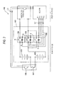
Fig. 2 shows an example of the above-described power supply circuit. As shown in the same figure, thepower supply circuit 100 includes abattery pack 101 disposed at the rear of the vehicle, aninverter 102 and amotor 103 that are disposed at the front of the vehicle as a load, an ECU 104 that is disposed at the front of the vehicle as a relay control unit that controls an operation of theinverter 102 and themotor 103. A high-voltage battery 105 is built in thebattery pack 101, and a direct current supplied from the high-voltage-battery 105 is converted to an alternating current power source by theinverter 102 and is supplied to themotor 103. - In addition, three
relays 106 provided between the high-voltage battery 105 and theinverter 102 are built in thebattery pack 101. Both ends of a relay coil C provided to each of therelays 106 are connected to the ECU 104. The ECU 104 controls the current passing through the relay coil C and thereby controls the turning on and off of a contact point S of each of therelays 106. - The high-
voltage battery 105 is an assembled battery in which batteries of a plurality of batteries are connected to each other in series, and aservice plug 107 is provided between the batteries. Theservice plug 107 is detachably provided between the batteries making up the high-voltage battery 105. When the service plug is detached, a supply of power from the high-voltage battery 105 to theinverter 102 and themotor 103 is blocked and when the service plug is attached, the supply of power from the high-voltage battery 105 to theinverter 102 and themotor 103 is enabled. Theservice plug 107 is provided with aninterlock switch 108 that detects the attachment and detachment of theservice plug 107. - The
interlock switch 108 is turned off when theservice plug 107 is detached, and is turned on when theservice plug 107 is attached. The ECU 104 is connected to theinterlock switch 108 with theinverter 102 and themotor 103 interposed therebetween, determines that theservice plug 107 is detached when theinterlock switch 108 is turned off, and blocks the current flowing through the relay coil C and turns off therelay 106. Therefore, it is possible to more reliably block the supply of power from the high-voltage battery 105 to theinverter 102 and themotor 103. -
- [PTL 1]
JP-A-2005-142107 - However, according to the above-described
power supply circuit 100, it is necessary to provide two electric wires L2 connecting theECU 104 provided at the front of the vehicle and theinterlock switch 108 provided at the rear of the vehicle to each other, in addition to an electric wire L1 connecting theECU 104 provided at the front of the vehicle and the relay coil C of therelay 106 provided at the rear of the vehicle, accordingly, the number of long electric wires close to the total length of the vehicle becomes large, resulting in problems of cost. - Therefore, an object of the invention is to provide a power supply circuit in which the number of electric wires is reduced and thereby cost reduction is realized.
- The invention for solving the above-described problems provides a power supply circuit: including a battery; a load to which power is supplied from the battery; a relay that is provided between the battery and the load; a relay control unit to which both ends of a relay coil provided in the relay are connected, and that controls current flowing through the relay coil by controlling a turning on and off of the relay; a blocking member that is detachably provided on a power supply path from the battery to the load, wherein when the blocking member is detached, the supply of power from the battery to the load is blocked and when the blocking member is attached, the supply of power from the battery to the load is enabled; and an interlock switch that is turned off when the blocking member is detached and is turned on when the blocking member is attached, wherein the interlock switch is connected between the relay control unit and the relay coil.
- In addition, in the power supply circuit of the invention, a plurality of the relays are provided, other ends of relay coils provided in the plurality of relays are collectively connected to each other and are connected to one ground terminal provided on the relay control unit, and the interlock switch is connected between the ground terminal of the relay control unit and a downstream side in relation to a connection point at which the other ends of the relay coils are collectively connected.
- According to the invention described above, the interlock switch is connected between the relay control unit and the relay coils, such that when the interlock switch is turned off, the flow of current to the relay coils is blocked and thereby the relays are turned off. Therefore, two electric wires connecting the relay control unit and the interlock switch can be detached while allowing the relays to be turned off when the interlock switch is turned off, whereby cost reduction can be realized.
- In addition, according to the invention, the interlock switch is connected between the ground terminal of the relay control unit and the downstream side in relation to the connection point at which the other ends of the relay coils are collectively connected, such that the plurality of relays can be turned off by the single interlock switch and thereby it is not necessary to provide the interlock switch for every relay, accordingly, cost reduction can be realized.
-
-
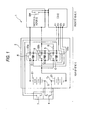
Fig. 1 is a circuit diagram illustrating a power supply circuit according to an embodiment of the invention. -
Fig. 2 is a circuit diagram illustrating a power supply circuit according to an example of the related art. - Hereinafter, an embodiment of the invention will be described on the basis of
Fig. 1 . As shown inFig.1 , the power supply circuit 1 includes abattery pack 2 disposed at the rear of a vehicle, aninverter 3 and amotor 4, which are disposed at the front of the vehicle, as a load, anECU 5, which is disposed at the front of the vehicle, as a relay control unit, aservice plug 6 as a blocking member, and an interlock switch 7. A high-voltage battery 21 as a battery, and threerelays 22a to 22c provided at both ends of the high-voltage battery 21 are built in thebattery pack 2. - The high-
voltage battery 21 has a high voltage by connecting, for example, six batteries in series. Contact points S of therelays voltage battery 21 and theinverter 3, respectively. A contact point S of therelay 22c and a current restriction resistor R for restricting a rush current are connected in parallel with therelay 22b. Therelay 22b is connected to a negative side of the high-voltage battery 21. - The turning on and off of the above-described
relays 22a to 22c is controlled by the ECU 5. TheECU 5 turns on therelays 22a to 22c according to a turning on of the ignition switch, for example, and begins to start the supply of power to theinverter 3 and themotor 4 from the high-current battery 21. At this time, theECU 5, first, turns on therelays relay 22b. Due to the current restriction resistor R, the rush current flowing from the high-voltage battery 21 to theinverter 3 is restricted. - The
inverter 3 is provided at a downstream side of therelays 22a to 22c, is operated by the supply of power from the high-voltage battery 21, and converts a direct current from the high-voltage battery 21 to an alternating current. Themotor 4 is provided at a downstream side of theinverter 3 and is operated by the supply of power from the high-voltage battery 21, which is converted to the alternating current by theinverter 3. - Both ends of each of the relay coils C provided in the
relays 22a to 22c are connected to theECU 5, and theECU 5 controls the current flowing through the relay coils C and thereby controls the turning on and off of therelays 22a to 22c. In other words, theECU 5 includes the same number of signal terminals T+ as the number of therelays 22a to 22c, to which one end of each of the three relay coils C is connected, respectively, and a ground terminal T- to which other ends of the relay coils C are collectively connected. The ground terminal T- is grounded. TheECU 5 controls an output of each of the signal terminals T+ and thereby controls the current flowing through the relay coils C. In addition, the ECU 5 is connected to a power switch SW that is built in theinverter 3 ormotor 4 and thereby controls the turning on and off of the power switch SW. - The
service plug 6 is formed of a fusible conductive member that is melted down when an overcurrent flows therethrough. Theservice plug 6 is provided such that it can be manually attached to and detached from mounting terminals T1 and T2, which are provided between batteries making up the high-voltage battery 21. When theservice plug 6 is detached, the supply of power from the high-voltage battery 21 to theinverter 3 and themotor 4 is blocked (shut off) and when theservice plug 6 is attached, the supply of power from the high-voltage battery 21 to theinverter 3 and themotor 4 is enabled. Theservice plug 6 is provided with an interlock switch 7 that detects the attachment and detachment of theservice plug 6. - The interlock switch 7 is turned off when the
service plug 6 is detached and is turned on when theservice plug 6 is attached. In addition, the interlock switch 7 is connected between the ground terminal T- and a downstream in relation to the connection point at which the other ends of the relay coils C are collectively connected. - According to the power supply circuit 1 with the above-described configuration, when the
service plug 6 is attached, if therelays 22a to 22c are turned on, a power supply path from the high-voltage battery 21 to theinverter 3 and themotor 4 is closed and thereby the supply of power from the high-voltage battery 21 to theinverter 3 and themotor 4 is enabled according to the turning on of therelays 22a to 22c. On the other hand, when theservice plug 6 is detached from the high-voltage battery 21 by a worker at the time of maintenance, the power supply path from the high-voltage battery 21 to theinverter 3 and themotor 4 is opened and thereby the supply of power from the high-voltage battery 21 to theinverter 3 and themotor 4 is blocked. - When the
service plug 6 is detached from the high-voltage battery 21 and thereby the interlock switch 7 is turned off, the flow of current from theECU 5 with respect to the relay coils C is blocked, accordingly, therelays 22a to 22c are turned off. Therefore, two electric wires L2 (Fig. 2 ) connecting theECU 5 and the interlock switch 7 can be reduced while allowing therelays 22a to 22c to be turned off when the interlock switch 7 is turned off, whereby cost reduction can be realized. - In addition, according to the above-described power supply circuit 1, the interlock switch 7 is connected between the ground terminal T- of the
ECU 5 and the downstream side in relation to the connection point at which the other ends of the relay coils C are collectively connected, such that the plurality ofrelays 22a to 22c can be turned off by the single interlock switch 7 and thereby it is not necessary to provide the interlock switch 7 for everyrelay 22a to 22c, accordingly, cost reduction can be realized. - In addition, according to the above-described embodiment, the
service plug 6 is detachably provided between the batteries making up the high-voltage battery 21, but the invention is not limited thereto. Theservice plug 6 may be detachably provided on the power supply path from the high-voltage battery 21 to theinverter 3 that is a load. - In addition, according to the above-described embodiment, the interlock switch 7 is connected between the ground terminal T- of the
ECU 5 and the downstream side in relation to the connection point at which the other ends of the relay coils C are collectively connected, but the invention is not limited thereto. If there are no problems in terms of cost, interlock switches 7 may be provided separately between one end of each of the relay coils 7 and the signal terminal T+, respectively. - In addition, the above-described embodiment merely represents a representative embodiment of the invention, and the invention is not limited by the above-described embodiment. That is to say, the invention may be implemented by various modifications made without departing from the scope of the invention.
- The invention is described in detail with reference to a specific embodiment, but it should be understood by those skilled in the art that various modifications and alterations may be made without departing from the spirit and the scope of the invention.
- The invention is based on Japanese Patent Application (
2009-245353) filed on October 26, 2009 -
- 3:
- INVERTER (LOAD)
- 4:
- MOTOR (LOAD)
- 5:
- ECU (RELAY CONTROL UNIT)
- 6:
- SERVICE PLUG (BLOCKING MEMBER)
- 7:
- INTERLOCK SWITCH
- 21:
- HIGH VOLTAGE BATTERY (BATTERY)
- 22a to 22c:
- RELAY
- c:
- RELAY COIL
Claims (2)
- A power supply circuit, comprising:a battery;a load to which power is supplied from the battery;a relay that is provided between the battery and the load;a relay control unit to which both ends of a relay coil provided in the relay are connected, and that controls current flowing through the relay coil by controlling a turning on and off of the relay;a blocking member that is detachably provided on a power supply path from the battery to the load, wherein when the blocking member is detached, the supply of power from the battery to the load is blocked and when the blocking member is attached, the supply of power from the battery to the load is enabled; andan interlock switch that is turned off when the blocking member is detached and is turned on when the blocking member is attached,wherein the interlock switch is connected between the relay control unit and the relay coil.
- The power supply circuit according to claim 1, wherein a plurality of the relays are provided,
wherein other ends of relay coils provided in the plurality of relays are collectively connected to each other and are connected to one ground terminal provided on the relay control unit; and
wherein the interlock switch is connected between the ground terminal of the relay control unit and a downstream side in relation to a connection point at which the other ends of the relay coils are collectively connected.
Applications Claiming Priority (2)
| Application Number | Priority Date | Filing Date | Title |
|---|---|---|---|
| JP2009245353A JP5805926B2 (en) | 2009-10-26 | 2009-10-26 | Power circuit |
| PCT/JP2010/069005 WO2011052609A1 (en) | 2009-10-26 | 2010-10-26 | Power supply circuit |
Publications (3)
| Publication Number | Publication Date |
|---|---|
| EP2495134A1 true EP2495134A1 (en) | 2012-09-05 |
| EP2495134A4 EP2495134A4 (en) | 2017-06-28 |
| EP2495134B1 EP2495134B1 (en) | 2020-05-06 |
Family
ID=43922034
Family Applications (1)
| Application Number | Title | Priority Date | Filing Date |
|---|---|---|---|
| EP10826741.0A Active EP2495134B1 (en) | 2009-10-26 | 2010-10-26 | Power supply circuit |
Country Status (5)
| Country | Link |
|---|---|
| US (1) | US8842408B2 (en) |
| EP (1) | EP2495134B1 (en) |
| JP (1) | JP5805926B2 (en) |
| CN (1) | CN102271968B (en) |
| WO (1) | WO2011052609A1 (en) |
Cited By (2)
| Publication number | Priority date | Publication date | Assignee | Title |
|---|---|---|---|---|
| CN112977067A (en) * | 2021-03-03 | 2021-06-18 | 南京恒天领锐汽车有限公司 | Electrifying strategy for high-voltage power distribution cabinet of pure electric logistics vehicle |
| DE102017112701B4 (en) | 2016-06-14 | 2026-02-12 | GM Global Technology Operations LLC | High-voltage electrical systems and disconnect devices |
Families Citing this family (13)
| Publication number | Priority date | Publication date | Assignee | Title |
|---|---|---|---|---|
| KR20130118539A (en) | 2012-04-20 | 2013-10-30 | 삼성에스디아이 주식회사 | Battery pack |
| DE102012210620A1 (en) * | 2012-06-22 | 2013-12-24 | Robert Bosch Gmbh | Method for monitoring a separating device, in particular a service plug or a service socket, in a battery system, and corresponding monitoring device |
| EP2684729B1 (en) * | 2012-07-12 | 2016-01-20 | Volvo Car Corporation | Contact arrangement for safe disconnection of a power supply in a vehicle |
| DE102012015523B4 (en) * | 2012-08-04 | 2015-04-02 | Audi Ag | High-voltage battery with discharge option after a crash |
| CN104781900B (en) * | 2013-02-14 | 2016-12-28 | 本田技研工业株式会社 | circuit disconnecting device |
| US20170203666A1 (en) * | 2016-01-19 | 2017-07-20 | Ford Global Technologies, Llc | Battery charging system and servicing method |
| JP6642088B2 (en) | 2016-02-18 | 2020-02-05 | 株式会社オートネットワーク技術研究所 | Electrical equipment |
| JP6604289B2 (en) | 2016-08-30 | 2019-11-13 | 株式会社オートネットワーク技術研究所 | Electrical junction box |
| FR3060832B1 (en) * | 2016-12-16 | 2019-05-17 | Airbus Group Sas | ELECTRIC POWER SWITCH AND VEHICLE HAVING SUCH A CONTACTOR |
| FR3074370B1 (en) * | 2017-11-30 | 2019-12-13 | Valeo Siemens Eautomotive France Sas | ELECTRIC DEVICE FOR ELECTRIC OR HYBRID VEHICLE |
| EP4124498A1 (en) * | 2021-07-26 | 2023-02-01 | Samsung SDI Co., Ltd. | Relay control system and battery system |
| CN115700185B (en) | 2021-07-26 | 2026-03-24 | 三星Sdi株式会社 | Relay control system and battery system |
| CN115360057B (en) * | 2022-08-12 | 2026-04-21 | 东风柳州汽车有限公司 | Relay control circuit, relay control method and electric vehicle |
Family Cites Families (16)
| Publication number | Priority date | Publication date | Assignee | Title |
|---|---|---|---|---|
| JP2765116B2 (en) * | 1989-10-31 | 1998-06-11 | スズキ株式会社 | Anti-theft device for motorcycles |
| US5336934A (en) * | 1992-12-17 | 1994-08-09 | Ford Motor Company | Electrical connection and interlock circuit system for vehicle electric drive |
| JP2000175305A (en) * | 1998-12-03 | 2000-06-23 | Toyota Motor Corp | Hybrid car |
| JP2004001652A (en) * | 2002-05-31 | 2004-01-08 | Sanyo Electric Co Ltd | Power unit for vehicle |
| JP4272037B2 (en) | 2003-11-10 | 2009-06-03 | 矢崎総業株式会社 | Lever fitting type power circuit breaker |
| JP2006136097A (en) * | 2004-11-04 | 2006-05-25 | Toyota Motor Corp | High voltage equipment storage box and vehicle |
| JP2006327251A (en) * | 2005-05-23 | 2006-12-07 | Toyota Motor Corp | Power supply circuit switchgear |
| JP2006337692A (en) * | 2005-06-01 | 2006-12-14 | Konica Minolta Business Technologies Inc | Image forming apparatus and power unit |
| JP4524661B2 (en) | 2005-10-06 | 2010-08-18 | 株式会社デンソー | Power generation control device |
| JP5024811B2 (en) * | 2006-03-17 | 2012-09-12 | 国立大学法人静岡大学 | Electric vehicle power supply device |
| JP4884089B2 (en) * | 2006-06-15 | 2012-02-22 | 三洋電機株式会社 | Power supply for vehicle |
| JP2008312396A (en) * | 2007-06-15 | 2008-12-25 | Yazaki Corp | Vehicle power supply system |
| JP5096837B2 (en) * | 2007-08-24 | 2012-12-12 | プライムアースEvエナジー株式会社 | POWER SUPPLY DEVICE AND SAFETY CIRCUIT HAVING THE SAME |
| US7586722B2 (en) * | 2007-09-18 | 2009-09-08 | Ford Global Technologies, Llc | High voltage interlock system and control strategy |
| JP2009245353A (en) | 2008-03-31 | 2009-10-22 | Nomura Research Institute Ltd | Information processing system and information processing method |
| US8513837B2 (en) * | 2009-07-28 | 2013-08-20 | Parker-Hannifin Corporation | Electrical interrupt system and method for use in a hybrid system |
-
2009
- 2009-10-26 JP JP2009245353A patent/JP5805926B2/en active Active
-
2010
- 2010-10-26 US US13/141,728 patent/US8842408B2/en active Active
- 2010-10-26 CN CN201080003891.6A patent/CN102271968B/en active Active
- 2010-10-26 EP EP10826741.0A patent/EP2495134B1/en active Active
- 2010-10-26 WO PCT/JP2010/069005 patent/WO2011052609A1/en not_active Ceased
Non-Patent Citations (1)
| Title |
|---|
| See references of WO2011052609A1 * |
Cited By (3)
| Publication number | Priority date | Publication date | Assignee | Title |
|---|---|---|---|---|
| DE102017112701B4 (en) | 2016-06-14 | 2026-02-12 | GM Global Technology Operations LLC | High-voltage electrical systems and disconnect devices |
| CN112977067A (en) * | 2021-03-03 | 2021-06-18 | 南京恒天领锐汽车有限公司 | Electrifying strategy for high-voltage power distribution cabinet of pure electric logistics vehicle |
| CN112977067B (en) * | 2021-03-03 | 2022-02-11 | 南京恒天领锐汽车有限公司 | Electrifying strategy for high-voltage power distribution cabinet of pure electric logistics vehicle |
Also Published As
| Publication number | Publication date |
|---|---|
| US8842408B2 (en) | 2014-09-23 |
| JP5805926B2 (en) | 2015-11-10 |
| CN102271968A (en) | 2011-12-07 |
| EP2495134B1 (en) | 2020-05-06 |
| US20110261498A1 (en) | 2011-10-27 |
| JP2011088598A (en) | 2011-05-06 |
| EP2495134A4 (en) | 2017-06-28 |
| CN102271968B (en) | 2014-02-26 |
| WO2011052609A1 (en) | 2011-05-05 |
Similar Documents
| Publication | Publication Date | Title |
|---|---|---|
| US8842408B2 (en) | Power supply circuit | |
| CN101888939B (en) | Method and apparatus for limiting the switch-on current and for discharging the DC voltage intermediate circuit | |
| KR102485328B1 (en) | Apparatus for charge controlling of electric vehicle | |
| US10661877B2 (en) | Electric drive for a vehicle | |
| JP5693922B2 (en) | Low voltage and high voltage integrated voltage distribution device | |
| US10583749B2 (en) | Battery system and method for the operation thereof | |
| CN112644284B (en) | Vehicle electrical network and method for operating such a vehicle electrical network | |
| KR20120062956A (en) | High voltage system of electric vehicles | |
| CN109649216A (en) | Automatic connection of drive battery | |
| KR102748613B1 (en) | Vehicle Electrical System | |
| CN107206906A (en) | High-tension battery and motor vehicle for motor vehicle | |
| CN110450675B (en) | Power battery system, control method and electric automobile | |
| CN206633943U (en) | A kind of fuel cell electric vehicle low-voltage distribution box | |
| CN105874631A (en) | Battery unit and vehicle electrical system with battery unit | |
| KR102171985B1 (en) | Emergency power supply device for eco-friendly vehicle | |
| EP3038226B1 (en) | System and method for supplying electric power | |
| US12325314B2 (en) | Vehicle on-board electrical system | |
| CN114927391A (en) | Fuse box, vehicle-mounted protection system and vehicle | |
| KR200482372Y1 (en) | Power relay assembly | |
| CN220884058U (en) | Vehicle power harness system and vehicle | |
| JP2015101288A (en) | Relay device for regenerative system | |
| CN102343830A (en) | High voltage distributor for hybrid electric vehicles or pure electric vehicles | |
| KR20260054944A (en) | PRA system | |
| WO2024071146A1 (en) | Electrical junction box for vehicle | |
| CN111697868A (en) | Integrated electric vehicle power conversion system |
Legal Events
| Date | Code | Title | Description |
|---|---|---|---|
| PUAI | Public reference made under article 153(3) epc to a published international application that has entered the european phase |
Free format text: ORIGINAL CODE: 0009012 |
|
| 17P | Request for examination filed |
Effective date: 20110627 |
|
| AK | Designated contracting states |
Kind code of ref document: A1 Designated state(s): AL AT BE BG CH CY CZ DE DK EE ES FI FR GB GR HR HU IE IS IT LI LT LU LV MC MK MT NL NO PL PT RO RS SE SI SK SM TR |
|
| DAX | Request for extension of the european patent (deleted) | ||
| RA4 | Supplementary search report drawn up and despatched (corrected) |
Effective date: 20170531 |
|
| RIC1 | Information provided on ipc code assigned before grant |
Ipc: B60L 3/04 20060101ALI20170524BHEP Ipc: B60L 11/18 20060101ALI20170524BHEP Ipc: B60R 16/02 20060101AFI20170524BHEP Ipc: B60L 3/00 20060101ALI20170524BHEP |
|
| STAA | Information on the status of an ep patent application or granted ep patent |
Free format text: STATUS: EXAMINATION IS IN PROGRESS |
|
| 17Q | First examination report despatched |
Effective date: 20180927 |
|
| GRAP | Despatch of communication of intention to grant a patent |
Free format text: ORIGINAL CODE: EPIDOSNIGR1 |
|
| STAA | Information on the status of an ep patent application or granted ep patent |
Free format text: STATUS: GRANT OF PATENT IS INTENDED |
|
| RIC1 | Information provided on ipc code assigned before grant |
Ipc: B60R 16/02 20060101AFI20191126BHEP Ipc: B60L 3/04 20060101ALI20191126BHEP Ipc: B60L 3/00 20190101ALI20191126BHEP Ipc: B60L 50/50 20190101ALI20191126BHEP |
|
| INTG | Intention to grant announced |
Effective date: 20191213 |
|
| RIN1 | Information on inventor provided before grant (corrected) |
Inventor name: HASEGAWA, HIROTAKA Inventor name: IKEDA, TOMOHIRO |
|
| GRAS | Grant fee paid |
Free format text: ORIGINAL CODE: EPIDOSNIGR3 |
|
| GRAA | (expected) grant |
Free format text: ORIGINAL CODE: 0009210 |
|
| STAA | Information on the status of an ep patent application or granted ep patent |
Free format text: STATUS: THE PATENT HAS BEEN GRANTED |
|
| AK | Designated contracting states |
Kind code of ref document: B1 Designated state(s): AL AT BE BG CH CY CZ DE DK EE ES FI FR GB GR HR HU IE IS IT LI LT LU LV MC MK MT NL NO PL PT RO RS SE SI SK SM TR |
|
| REG | Reference to a national code |
Ref country code: GB Ref legal event code: FG4D |
|
| REG | Reference to a national code |
Ref country code: CH Ref legal event code: EP Ref country code: AT Ref legal event code: REF Ref document number: 1266245 Country of ref document: AT Kind code of ref document: T Effective date: 20200515 |
|
| REG | Reference to a national code |
Ref country code: IE Ref legal event code: FG4D |
|
| REG | Reference to a national code |
Ref country code: DE Ref legal event code: R096 Ref document number: 602010064275 Country of ref document: DE |
|
| REG | Reference to a national code |
Ref country code: LT Ref legal event code: MG4D |
|
| REG | Reference to a national code |
Ref country code: NL Ref legal event code: MP Effective date: 20200506 |
|
| PG25 | Lapsed in a contracting state [announced via postgrant information from national office to epo] |
Ref country code: FI Free format text: LAPSE BECAUSE OF FAILURE TO SUBMIT A TRANSLATION OF THE DESCRIPTION OR TO PAY THE FEE WITHIN THE PRESCRIBED TIME-LIMIT Effective date: 20200506 Ref country code: PT Free format text: LAPSE BECAUSE OF FAILURE TO SUBMIT A TRANSLATION OF THE DESCRIPTION OR TO PAY THE FEE WITHIN THE PRESCRIBED TIME-LIMIT Effective date: 20200907 Ref country code: LT Free format text: LAPSE BECAUSE OF FAILURE TO SUBMIT A TRANSLATION OF THE DESCRIPTION OR TO PAY THE FEE WITHIN THE PRESCRIBED TIME-LIMIT Effective date: 20200506 Ref country code: IS Free format text: LAPSE BECAUSE OF FAILURE TO SUBMIT A TRANSLATION OF THE DESCRIPTION OR TO PAY THE FEE WITHIN THE PRESCRIBED TIME-LIMIT Effective date: 20200906 Ref country code: SE Free format text: LAPSE BECAUSE OF FAILURE TO SUBMIT A TRANSLATION OF THE DESCRIPTION OR TO PAY THE FEE WITHIN THE PRESCRIBED TIME-LIMIT Effective date: 20200506 Ref country code: GR Free format text: LAPSE BECAUSE OF FAILURE TO SUBMIT A TRANSLATION OF THE DESCRIPTION OR TO PAY THE FEE WITHIN THE PRESCRIBED TIME-LIMIT Effective date: 20200807 Ref country code: NO Free format text: LAPSE BECAUSE OF FAILURE TO SUBMIT A TRANSLATION OF THE DESCRIPTION OR TO PAY THE FEE WITHIN THE PRESCRIBED TIME-LIMIT Effective date: 20200806 |
|
| PG25 | Lapsed in a contracting state [announced via postgrant information from national office to epo] |
Ref country code: BG Free format text: LAPSE BECAUSE OF FAILURE TO SUBMIT A TRANSLATION OF THE DESCRIPTION OR TO PAY THE FEE WITHIN THE PRESCRIBED TIME-LIMIT Effective date: 20200806 Ref country code: RS Free format text: LAPSE BECAUSE OF FAILURE TO SUBMIT A TRANSLATION OF THE DESCRIPTION OR TO PAY THE FEE WITHIN THE PRESCRIBED TIME-LIMIT Effective date: 20200506 Ref country code: HR Free format text: LAPSE BECAUSE OF FAILURE TO SUBMIT A TRANSLATION OF THE DESCRIPTION OR TO PAY THE FEE WITHIN THE PRESCRIBED TIME-LIMIT Effective date: 20200506 Ref country code: LV Free format text: LAPSE BECAUSE OF FAILURE TO SUBMIT A TRANSLATION OF THE DESCRIPTION OR TO PAY THE FEE WITHIN THE PRESCRIBED TIME-LIMIT Effective date: 20200506 |
|
| REG | Reference to a national code |
Ref country code: AT Ref legal event code: MK05 Ref document number: 1266245 Country of ref document: AT Kind code of ref document: T Effective date: 20200506 |
|
| PG25 | Lapsed in a contracting state [announced via postgrant information from national office to epo] |
Ref country code: NL Free format text: LAPSE BECAUSE OF FAILURE TO SUBMIT A TRANSLATION OF THE DESCRIPTION OR TO PAY THE FEE WITHIN THE PRESCRIBED TIME-LIMIT Effective date: 20200506 Ref country code: AL Free format text: LAPSE BECAUSE OF FAILURE TO SUBMIT A TRANSLATION OF THE DESCRIPTION OR TO PAY THE FEE WITHIN THE PRESCRIBED TIME-LIMIT Effective date: 20200506 |
|
| PG25 | Lapsed in a contracting state [announced via postgrant information from national office to epo] |
Ref country code: ES Free format text: LAPSE BECAUSE OF FAILURE TO SUBMIT A TRANSLATION OF THE DESCRIPTION OR TO PAY THE FEE WITHIN THE PRESCRIBED TIME-LIMIT Effective date: 20200506 Ref country code: DK Free format text: LAPSE BECAUSE OF FAILURE TO SUBMIT A TRANSLATION OF THE DESCRIPTION OR TO PAY THE FEE WITHIN THE PRESCRIBED TIME-LIMIT Effective date: 20200506 Ref country code: SM Free format text: LAPSE BECAUSE OF FAILURE TO SUBMIT A TRANSLATION OF THE DESCRIPTION OR TO PAY THE FEE WITHIN THE PRESCRIBED TIME-LIMIT Effective date: 20200506 Ref country code: IT Free format text: LAPSE BECAUSE OF FAILURE TO SUBMIT A TRANSLATION OF THE DESCRIPTION OR TO PAY THE FEE WITHIN THE PRESCRIBED TIME-LIMIT Effective date: 20200506 Ref country code: CZ Free format text: LAPSE BECAUSE OF FAILURE TO SUBMIT A TRANSLATION OF THE DESCRIPTION OR TO PAY THE FEE WITHIN THE PRESCRIBED TIME-LIMIT Effective date: 20200506 Ref country code: EE Free format text: LAPSE BECAUSE OF FAILURE TO SUBMIT A TRANSLATION OF THE DESCRIPTION OR TO PAY THE FEE WITHIN THE PRESCRIBED TIME-LIMIT Effective date: 20200506 Ref country code: AT Free format text: LAPSE BECAUSE OF FAILURE TO SUBMIT A TRANSLATION OF THE DESCRIPTION OR TO PAY THE FEE WITHIN THE PRESCRIBED TIME-LIMIT Effective date: 20200506 Ref country code: RO Free format text: LAPSE BECAUSE OF FAILURE TO SUBMIT A TRANSLATION OF THE DESCRIPTION OR TO PAY THE FEE WITHIN THE PRESCRIBED TIME-LIMIT Effective date: 20200506 |
|
| REG | Reference to a national code |
Ref country code: DE Ref legal event code: R097 Ref document number: 602010064275 Country of ref document: DE |
|
| PG25 | Lapsed in a contracting state [announced via postgrant information from national office to epo] |
Ref country code: PL Free format text: LAPSE BECAUSE OF FAILURE TO SUBMIT A TRANSLATION OF THE DESCRIPTION OR TO PAY THE FEE WITHIN THE PRESCRIBED TIME-LIMIT Effective date: 20200506 Ref country code: SK Free format text: LAPSE BECAUSE OF FAILURE TO SUBMIT A TRANSLATION OF THE DESCRIPTION OR TO PAY THE FEE WITHIN THE PRESCRIBED TIME-LIMIT Effective date: 20200506 |
|
| PLBE | No opposition filed within time limit |
Free format text: ORIGINAL CODE: 0009261 |
|
| STAA | Information on the status of an ep patent application or granted ep patent |
Free format text: STATUS: NO OPPOSITION FILED WITHIN TIME LIMIT |
|
| 26N | No opposition filed |
Effective date: 20210209 |
|
| PG25 | Lapsed in a contracting state [announced via postgrant information from national office to epo] |
Ref country code: SI Free format text: LAPSE BECAUSE OF FAILURE TO SUBMIT A TRANSLATION OF THE DESCRIPTION OR TO PAY THE FEE WITHIN THE PRESCRIBED TIME-LIMIT Effective date: 20200506 |
|
| REG | Reference to a national code |
Ref country code: CH Ref legal event code: PL |
|
| GBPC | Gb: european patent ceased through non-payment of renewal fee |
Effective date: 20201026 |
|
| PG25 | Lapsed in a contracting state [announced via postgrant information from national office to epo] |
Ref country code: LU Free format text: LAPSE BECAUSE OF NON-PAYMENT OF DUE FEES Effective date: 20201026 Ref country code: MC Free format text: LAPSE BECAUSE OF FAILURE TO SUBMIT A TRANSLATION OF THE DESCRIPTION OR TO PAY THE FEE WITHIN THE PRESCRIBED TIME-LIMIT Effective date: 20200506 |
|
| REG | Reference to a national code |
Ref country code: BE Ref legal event code: MM Effective date: 20201031 |
|
| PG25 | Lapsed in a contracting state [announced via postgrant information from national office to epo] |
Ref country code: CH Free format text: LAPSE BECAUSE OF NON-PAYMENT OF DUE FEES Effective date: 20201031 Ref country code: BE Free format text: LAPSE BECAUSE OF NON-PAYMENT OF DUE FEES Effective date: 20201031 Ref country code: LI Free format text: LAPSE BECAUSE OF NON-PAYMENT OF DUE FEES Effective date: 20201031 Ref country code: GB Free format text: LAPSE BECAUSE OF NON-PAYMENT OF DUE FEES Effective date: 20201026 |
|
| PG25 | Lapsed in a contracting state [announced via postgrant information from national office to epo] |
Ref country code: IE Free format text: LAPSE BECAUSE OF NON-PAYMENT OF DUE FEES Effective date: 20201026 |
|
| PG25 | Lapsed in a contracting state [announced via postgrant information from national office to epo] |
Ref country code: TR Free format text: LAPSE BECAUSE OF FAILURE TO SUBMIT A TRANSLATION OF THE DESCRIPTION OR TO PAY THE FEE WITHIN THE PRESCRIBED TIME-LIMIT Effective date: 20200506 Ref country code: MT Free format text: LAPSE BECAUSE OF FAILURE TO SUBMIT A TRANSLATION OF THE DESCRIPTION OR TO PAY THE FEE WITHIN THE PRESCRIBED TIME-LIMIT Effective date: 20200506 Ref country code: CY Free format text: LAPSE BECAUSE OF FAILURE TO SUBMIT A TRANSLATION OF THE DESCRIPTION OR TO PAY THE FEE WITHIN THE PRESCRIBED TIME-LIMIT Effective date: 20200506 |
|
| PG25 | Lapsed in a contracting state [announced via postgrant information from national office to epo] |
Ref country code: MK Free format text: LAPSE BECAUSE OF FAILURE TO SUBMIT A TRANSLATION OF THE DESCRIPTION OR TO PAY THE FEE WITHIN THE PRESCRIBED TIME-LIMIT Effective date: 20200506 |
|
| PGFP | Annual fee paid to national office [announced via postgrant information from national office to epo] |
Ref country code: FR Payment date: 20250908 Year of fee payment: 16 |
|
| PGFP | Annual fee paid to national office [announced via postgrant information from national office to epo] |
Ref country code: DE Payment date: 20250902 Year of fee payment: 16 |