EP2493033B1 - Périphérique de stockage externe - Google Patents
Périphérique de stockage externe Download PDFInfo
- Publication number
- EP2493033B1 EP2493033B1 EP12153313.7A EP12153313A EP2493033B1 EP 2493033 B1 EP2493033 B1 EP 2493033B1 EP 12153313 A EP12153313 A EP 12153313A EP 2493033 B1 EP2493033 B1 EP 2493033B1
- Authority
- EP
- European Patent Office
- Prior art keywords
- substrate
- storage device
- external storage
- memory die
- features
- Prior art date
- Legal status (The legal status is an assumption and is not a legal conclusion. Google has not performed a legal analysis and makes no representation as to the accuracy of the status listed.)
- Active
Links
- 238000003860 storage Methods 0.000 title claims description 56
- 239000000758 substrate Substances 0.000 claims description 69
- 230000008878 coupling Effects 0.000 claims description 44
- 238000010168 coupling process Methods 0.000 claims description 44
- 238000005859 coupling reaction Methods 0.000 claims description 44
- 238000013461 design Methods 0.000 description 15
- 239000000463 material Substances 0.000 description 8
- 230000009977 dual effect Effects 0.000 description 5
- 238000009826 distribution Methods 0.000 description 2
- 238000012545 processing Methods 0.000 description 2
- 239000007787 solid Substances 0.000 description 2
- 238000012546 transfer Methods 0.000 description 2
- 208000025967 Dissociative Identity disease Diseases 0.000 description 1
- 239000004593 Epoxy Substances 0.000 description 1
- 230000006978 adaptation Effects 0.000 description 1
- 238000005452 bending Methods 0.000 description 1
- 238000010276 construction Methods 0.000 description 1
- 238000013500 data storage Methods 0.000 description 1
- 229920001971 elastomer Polymers 0.000 description 1
- 239000003292 glue Substances 0.000 description 1
- 239000004816 latex Substances 0.000 description 1
- 229920000126 latex Polymers 0.000 description 1
- 238000004519 manufacturing process Methods 0.000 description 1
- 239000002184 metal Substances 0.000 description 1
- 238000000034 method Methods 0.000 description 1
- 238000012986 modification Methods 0.000 description 1
- 230000004048 modification Effects 0.000 description 1
- 229920003023 plastic Polymers 0.000 description 1
- 239000004033 plastic Substances 0.000 description 1
- 229920000642 polymer Polymers 0.000 description 1
- 229920001296 polysiloxane Polymers 0.000 description 1
- 239000012858 resilient material Substances 0.000 description 1
- 239000000565 sealant Substances 0.000 description 1
- 230000011664 signaling Effects 0.000 description 1
- 229910000679 solder Inorganic materials 0.000 description 1
- 230000007704 transition Effects 0.000 description 1
- 238000011144 upstream manufacturing Methods 0.000 description 1
Images


Classifications
-
- H—ELECTRICITY
- H01—ELECTRIC ELEMENTS
- H01R—ELECTRICALLY-CONDUCTIVE CONNECTIONS; STRUCTURAL ASSOCIATIONS OF A PLURALITY OF MUTUALLY-INSULATED ELECTRICAL CONNECTING ELEMENTS; COUPLING DEVICES; CURRENT COLLECTORS
- H01R27/00—Coupling parts adapted for co-operation with two or more dissimilar counterparts
-
- G—PHYSICS
- G06—COMPUTING; CALCULATING OR COUNTING
- G06F—ELECTRIC DIGITAL DATA PROCESSING
- G06F13/00—Interconnection of, or transfer of information or other signals between, memories, input/output devices or central processing units
- G06F13/38—Information transfer, e.g. on bus
- G06F13/382—Information transfer, e.g. on bus using universal interface adapter
- G06F13/385—Information transfer, e.g. on bus using universal interface adapter for adaptation of a particular data processing system to different peripheral devices
-
- G—PHYSICS
- G06—COMPUTING; CALCULATING OR COUNTING
- G06F—ELECTRIC DIGITAL DATA PROCESSING
- G06F13/00—Interconnection of, or transfer of information or other signals between, memories, input/output devices or central processing units
- G06F13/38—Information transfer, e.g. on bus
- G06F13/40—Bus structure
- G06F13/4063—Device-to-bus coupling
- G06F13/409—Mechanical coupling
-
- H—ELECTRICITY
- H01—ELECTRIC ELEMENTS
- H01R—ELECTRICALLY-CONDUCTIVE CONNECTIONS; STRUCTURAL ASSOCIATIONS OF A PLURALITY OF MUTUALLY-INSULATED ELECTRICAL CONNECTING ELEMENTS; COUPLING DEVICES; CURRENT COLLECTORS
- H01R13/00—Details of coupling devices of the kinds covered by groups H01R12/70 or H01R24/00 - H01R33/00
- H01R13/66—Structural association with built-in electrical component
- H01R13/665—Structural association with built-in electrical component with built-in electronic circuit
- H01R13/6658—Structural association with built-in electrical component with built-in electronic circuit on printed circuit board
-
- H—ELECTRICITY
- H01—ELECTRIC ELEMENTS
- H01R—ELECTRICALLY-CONDUCTIVE CONNECTIONS; STRUCTURAL ASSOCIATIONS OF A PLURALITY OF MUTUALLY-INSULATED ELECTRICAL CONNECTING ELEMENTS; COUPLING DEVICES; CURRENT COLLECTORS
- H01R24/00—Two-part coupling devices, or either of their cooperating parts, characterised by their overall structure
- H01R24/60—Contacts spaced along planar side wall transverse to longitudinal axis of engagement
- H01R24/62—Sliding engagements with one side only, e.g. modular jack coupling devices
-
- H—ELECTRICITY
- H01—ELECTRIC ELEMENTS
- H01R—ELECTRICALLY-CONDUCTIVE CONNECTIONS; STRUCTURAL ASSOCIATIONS OF A PLURALITY OF MUTUALLY-INSULATED ELECTRICAL CONNECTING ELEMENTS; COUPLING DEVICES; CURRENT COLLECTORS
- H01R13/00—Details of coupling devices of the kinds covered by groups H01R12/70 or H01R24/00 - H01R33/00
- H01R13/40—Securing contact members in or to a base or case; Insulating of contact members
- H01R13/405—Securing in non-demountable manner, e.g. moulding, riveting
-
- H—ELECTRICITY
- H01—ELECTRIC ELEMENTS
- H01R—ELECTRICALLY-CONDUCTIVE CONNECTIONS; STRUCTURAL ASSOCIATIONS OF A PLURALITY OF MUTUALLY-INSULATED ELECTRICAL CONNECTING ELEMENTS; COUPLING DEVICES; CURRENT COLLECTORS
- H01R2107/00—Four or more poles
-
- H—ELECTRICITY
- H01—ELECTRIC ELEMENTS
- H01R—ELECTRICALLY-CONDUCTIVE CONNECTIONS; STRUCTURAL ASSOCIATIONS OF A PLURALITY OF MUTUALLY-INSULATED ELECTRICAL CONNECTING ELEMENTS; COUPLING DEVICES; CURRENT COLLECTORS
- H01R24/00—Two-part coupling devices, or either of their cooperating parts, characterised by their overall structure
- H01R24/60—Contacts spaced along planar side wall transverse to longitudinal axis of engagement
- H01R24/62—Sliding engagements with one side only, e.g. modular jack coupling devices
- H01R24/64—Sliding engagements with one side only, e.g. modular jack coupling devices for high frequency, e.g. RJ 45
Definitions
- the invention relates to mobile storage devices and the like.
- USB sticks consist of a memory data storage device integrated with a USB interface. USB sticks are typically used for similar purposes for which floppy disks or CD-ROMs were previously used. However, USB sticks are smaller, faster, have thousands of times more capacity, and are more durable and reliable.
- COB chip on board
- a USB controller and flash memory can be combined into one structure that is embedded into one side of a printed circuit board (“PCB”) with the USB connection located on an opposing surface.
- USB 1.1 The USB standard that governs the design of the USB connections has undergone several revisions since its earliest release in 1994.
- the first widely adopted version, USB 1.1 specified data rates of 1.5 Mbit/s ("Low-Bandwidth") and 12 Mbit/s ("Full-Bandwidth”).
- USB 1.1 was replaced by USB 2.0 in 2000.
- USB 2.0 provided a higher maximum data rate of 480 Mbit/s ("Hi-Speed").
- the USB 2.0 cable has four wires: two wires for power (+5 volts and ground) and a twisted pair of wires for carrying data.
- data is transmitted in one direction at a time (downstream or upstream).
- USB 3.0 includes a new "SuperSpeed" bus, which provides a fourth data transfer mode at 5.0 Gbit/s.
- the USB 3.0 cable has a total of eight wires: two wires for power (+5 volts and ground), the twisted pair for carrying non-SuperSpeed data (allows backward compatibility with earlier versions of USB devices), and two differential pairs for carrying SuperSpeed data. Full-duplex signaling occurs over the two differential pairs.
- USB 3.0 To date, adoption of the USB 3.0 standard has been slow due to the need to redesign motherboard hardware that supports the USB 3.0 standard, and the need to revise operating systems to support the USB 3.0 standard. To ease the transition to the USB 3.0 standard, it is desirable to modify existing USB 2.0 COB sticks to also include USB 3.0 connections.
- USB 2.0 COB stick configuration has a rectilinear design with the components embedded on one side of the PCB and the USB 2.0 connections positioned flush with the opposing side of the PCB, the shape and configuration does not readily allow the addition of a USB 3.0 connection to the existing USB 2.0 COB stick.
- USB 3.0 being the coming standard and much faster than USB 2.0, it is desirable to provide a design that incorporates USB 3.0 connections into existing USB 2.0 COB sticks so that the USB COB stick may connect to either version of the USB standard.
- Publication no. US 2008/0218799 A1 discloses a dual-personality extended USB (EUSB) system that supports both USB and EUSB memory cards using an extended 9-pin EUSB socket.
- Publication no. TWM387417U1 discloses a USB connector comprising a substrate having a plurality of first contact pads and a plurality of second contact pads exposed to the substrate, and aconnector having a plurality of slots and a plurality of terminals.
- inventions may comprise an external storage device having a substrate, a controller electrically coupled to the substrate, at least one memory die stack electrically coupled to the substrate, a plurality of connection fingers electrically coupled to the substrate, and a mounting bar electrically coupled to the substrate.
- the external storage device may be configured to support at least two USB standards with interfaces that are mechanically different.
- the mounting bar may be mounted to a component surface of the substrate and may be substantially enclosed by an outer casing that surrounds the substrate. In these features, the external storage device may comprise substantially flat surfaces on all sides.
- the mounting bar may also comprises a plurality of springs.
- the plurality of springs may include a coupling projection positioned proximate an end of each spring. The coupling projections may be configured to extend through a plurality of apertures in the component surface in an uncompressed position.
- the external storage device may comprise the substrate, the controller electrically coupled to the substrate, the memory die stack electrically coupled to the substrate, the plurality of connection fingers electrically coupled to the substrate, and a contact bar electrically coupled to the substrate.
- the external storage device may be configured to support at least two USB standards with interfaces that are mechanically different.
- the contact bar may be mounted to a connection surface of the substrate and may also include a cover.
- the contact bar comprises a plurality of extensions.
- the plurality of extensions may include a coupling projection positioned proximate an end of each extension. The coupling projections may be configured to extend through a plurality of apertures in the cover in an uncompressed position.
- the memory die stack may be mounted to the component surface or a connection surface of the substrate.
- the external storage device further comprises a plurality of memory die stacks.
- at least one of the memory die stacks is attached to a connection surface of the substrate, and at least one of the memory die stacks is attached to a component surface of the substrate.
- the memory die stacks may each comprise a plurality of dies. In some features, at least two of the memory die stacks are stacked in an overlapping arrangement.
- the described features of the invention provide external storage devices for use with multiple interface connection standards. While the designs are discussed for use with external storage devices, they are by no means so limited. Rather, features of these designs may be used for other devices that couple to any type of serial bus connection, parallel bus connection, or otherwise as desired.
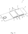
- Figures 1-34 illustrate features of an external storage device 10.
- the device 10 comprises a substrate 12, a connector 14, a controller 16, and at least one memory die stack 18.
- the substrate 12 may be a printed circuit board ("PCB"), which is used to mechanically support and electrically connect the other components of the device 10.
- the substrate 12 can include a component surface 24 and a connection surface 26. Items such as an oscillator, an LED status light, discrete components, or other suitable devices, may be mounted and electrically coupled to the component surface 24 and/or the connection surface 26.
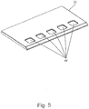
- the connector 14 may be positioned proximate an end 46 of the substrate 12 and configured to be inserted within a corresponding connector.
- the connector 14 may be configured to couple to a corresponding USB 2.0 connector, USB 3.0 connector, or any other standard that is forward or backwards compatible with any of the foregoing USB standards, other suitable serial bus connection, parallel bus connection, or otherwise as desired.
- the connection standards may be any suitable connection standards that achieve the desired performance of the device 10.
- the connector 14 may comprise a plurality of connection fingers 20 and a contact bar 22.
- the connection fingers 20 may be mounted to or embedded within the connection surface 26 of the substrate 12 and electrically coupled to the substrate 12.
- the connection fingers 20 may be configured to electrically couple to the power and ground wires and the twisted pair of wires (for Hi-Speed and lower data transfer) of the corresponding USB 2.0 connector when the connector 14 is inserted within the corresponding USB 2.0 connector.
- the connector 14 may comprise four connection fingers 20.
- any suitable number and configuration of connection fingers 20 may be used in conjunction with the USB 2.0 standard or other suitable standards.
- the contact bar 22 may be mounted to the connection surface 26 and electrically coupled to the substrate 12 via a plurality of coupling points 28.
- the substrate 12 comprises five coupling points 28.
- the coupling points 28 are configured to electrically couple to other types of additional components.
- the contact bar 22 forms a projection on the otherwise substantially flat connection surface 26.
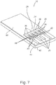
- the contact bar 22 comprises a board 30 and a cover 32.
- the board 30 may be a PCB, where an end 34 of the board 30 can include a plurality of connection pads 36.
- the board 30 may comprise five connection pads 36, as shown in Figures 4 and 6-7 .
- any suitable number and configuration of connection pads 36 may be used in conjunction with the USB 3.0 standard or other suitable standards.
- connection pads 36 may be positioned on the board 30 so as to substantially align with the position of the coupling points 28 when the contact bar 22 is mounted to the connection surface 26, as illustrated in Figure 7 .
- the connection pads 36 may be soldered or otherwise electrically coupled to the coupling points 28 in a suitable manner that allows each connection pad 36 to be electrically connected to the corresponding coupling point 28.
- the coupling points 28 may be mounted to or embedded within the connection surface 26 of the substrate 12 and electrically coupled to the substrate 12. In these features, the coupling points 28 may be positioned adjacent and/or behind the connection fingers 20. In other features, the coupling points 28 may be mounted to or embedded within the component surface 24, while the connection fingers 20 may be mounted to or embedded within the connection surface 26, or vice versa. One of ordinary skill in the relevant art will understand that the coupling points 28 may be positioned in any suitable location on the substrate 12 that allows the contact bar 22 to electrically couple to the substrate 12.
- the board 30 can include a plurality of extensions 38, as best shown in Figures 4 and 6-7 .
- each extension 38 may also be a PCB having some resilient attributes that cause the extension 38, when bent, to exert a force to return to its original position.
- the extensions 38 may be made of any suitable material and have any suitable design that allows the contact bar 22 to electrically couple to the corresponding connector when the connector 14 is inserted within the corresponding connector.
- each extension 38 can include a coupling projection 40 positioned proximate an end 42 of each extension 38.
- the coupling projection 40 may be soldered or otherwise electrically coupled to the extension 38 in a suitable manner that allows the coupling projection 40 to be electrically coupled to the corresponding connection pad 36.
- the coupling projection 40 may have any suitable shape that provides sufficient contact with the corresponding connector when the connector 14 is inserted within the corresponding connector. Examples of suitable shapes include but are not limited to a triangular, L-shape, U-shape, T-shape, solid projection having a circular or rectilinear cross-sectional shape, or other suitable shapes.
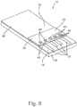
- the cover 32 may be positioned over the board 30.
- the cover 32 may be formed of materials including but not limited to any high thermal-resistant plastics, polymers, or other suitable materials.
- the cover 32 may also include a plurality of apertures 44 positioned over the plurality of extensions 38 and proximate the end 42 of each extension 38. The apertures 44 are configured to allow the coupling projections 40 to extend through the apertures 44 when the extensions 38 are in an uncompressed position.
- the connector 14 may be positioned proximate the end 46 of the substrate 12 so that the connection fingers 20 (when inserted within the corresponding USB 2.0 connector or any other standard that is forward or backwards compatible with the USB 2.0 standard) or the connection fingers 20 and coupling projections 40 (when inserted within the corresponding USB 3.0 connector or any other standard that is forward or backwards compatible with the USB 3.0 standard) electrically couple to the corresponding USB connector.
- the USB 3.0 connector presses against the coupling projections 40, in turn applying a bending force to the extensions 38.
- a ball 48 may be positioned on the end 42 of each extension 38 opposite the coupling projection 40.
- the ball 48 may be formed of materials including but not limited to silicone, normal rubber, latex, or other suitable materials.
- the ball 48 may be a metal spring or a micro spring.
- the ball 48 may have any suitable construction or form that provides elastic properties to the extension 38.
- the ball 48 provides additional force to create a firm electrical coupling between the corresponding USB 3.0 connector and each coupling projection 40 when the connector 14 is inserted within the corresponding USB 3.0 connector because the ball 48 is at least partially compressed when the connector 14 is inserted within the corresponding USB 3.0 connector.
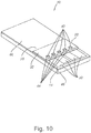
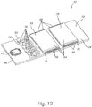
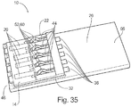
- the connector 14 may comprise the plurality of connection fingers 20 discussed above, along with a mounting bar 50.
- the mounting bar 50 is positioned on the component surface 24 so that the connection surface 26 may remain substantially flat if desirable.
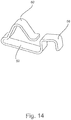
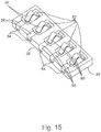
- the mounting bar 50 may comprise a plurality of contact springs 52.
- Each spring 52 may be formed of a resilient material that, when bent or compressed, exerts a force to return to its original shape.
- the springs 52 may be made of any suitable material and have any suitable design that allows the mounting bar 50 to electrically couple to the corresponding connector when the connector 14 is inserted within the corresponding connector.
- the mounting bar 50 may also include a plurality of receptacles 54 that are shaped to receive the contact springs 52.
- each spring 52 may include a hook 56 that mounts and electrically couples the spring 52 to an edge 58 of the mounting bar 50, which is best shown in Figure 15 .
- the hook 56 may have a U-shape that substantially conforms to the shape of the edge 58.
- the hook 56 may be substantially straight and configured to be inserted within a corresponding aperture on the edge 58.
- any suitable coupling arrangement may be used between the hook 56 and the edge 58.
- Each spring 52 may also include a coupling projection 60, as best illustrated in Figures 14-15 .
- the coupling projection 60 may be integrally formed with the spring 52.
- the coupling projection 60 may be soldered or otherwise electrically coupled to the spring 52 in a suitable manner that allows the coupling projection 60 to be electrically coupled to the substrate 12.
- the coupling projection 60 may have any suitable shape that provides sufficient contact with the corresponding connector when the connector 14 is inserted within the corresponding connector. Examples of suitable shapes include but are not limited to a triangular, L-shape, U-shape, T-shape, solid projection having a circular or rectilinear cross-sectional shape, or other suitable shapes.
- the mounting bar 50 may be mounted to and electrically coupled directly to the substrate 12.
- the mounting bar 50 is electrically coupled directly to the substrate 12 without the need to solder the mounting bar 50 to a plurality of coupling points 28.
- any suitable configuration of the mounting bar 50 and/or springs 52 may be used in conjunction with the USB 3.0 standard or other suitable standards.
- the mounting bar 50 may be positioned in any suitable orientation relative to the substrate 12.
- the mounting bar 50 may then electrically couple the substrate 12 to the corresponding connector via the coupling projections 60.
- a plurality of apertures 62 are positioned in the component surface 24 adjacent the plurality of connection fingers 20.
- the coupling projections 60 are configured to extend through the apertures 62 when the springs 52 are in an uncompressed position.
- the USB 3.0 connector presses against the coupling projections 60, in turn applying a compressive force to the springs 52.
- the spring-loaded design of each spring 52 then applies a force to create a firm electrical coupling between the USB 3.0 connector and each coupling projection 60 when the connector 14 is inserted within the corresponding USB 3.0 connector.
- an outer casing 66 may be applied to enclose the assembled substrate 12 and components.
- a sealant may be applied to the mounting bar 50 to prevent the case material from flowing into the mounting bar 50 and the internal assembly of the device 10 during the assembly process.
- glue or epoxy may be used to ensure a tight connection and avoid having the case material introduced into the space below the contact bar 22.
- the mounting bar 50 does not form a projection on the otherwise substantially flat connection surface 26.
- the thickness of the mounting bar 50 may not exceed the thicknesses of the other components positioned on the component surface 24, thus allowing at least the mounting bar 50 portion of the connector 14 to be incorporated into the existing dimensions of the device 10.
- the retractable design of the contact springs 52 may allow the coupling projections 60 to completely retract within the outer casing 66 when the device 10 is inserted within a corresponding USB 2.0 connector.
- the manufacturing throughput is improved because the device 10 is assembled as one single part, which is easy to handle by pick and place assembly machines.
- the connector 14 may comprise a combination of the contact bar 22 and the springs 52 discussed above.
- the connection fingers 20 may be mounted to or embedded within the cover 32 of the contact bar 22 and electrically coupled to the substrate 12.
- the cover 32 may also include the plurality of apertures 44 positioned adjacent and/or behind the connection fingers 20.
- Each spring 52 may be mounted to the contact bar 22 so that the coupling projection 60 extends through each aperture 44 when the springs 52 are in an uncompressed position.
- Each spring 52 may also include the connection pad 36, which may be integrally formed with the spring 52, soldered or otherwise electrically coupled to the spring 52 in a suitable matter that allows the coupling projection 60 to electrically couple to the substrate 12.
- the memory die stack 18 may include at least one die 64.
- each memory die stack 18 can include a single die 64.
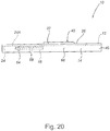
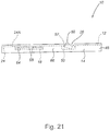
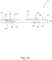
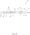
- the memory die stacks 18 shown in Figures 20-21 and 24-30 can include two dies 64 in each memory die stack 18.
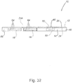
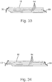
- Each memory die stack 18 shown in Figures 31-34 may include four dies 64 within each memory die stack 18.
- One of ordinary skill in the relevant art will understand that the memory die stack 18 may include 1, 2, 4, or any suitable number of dies 64.
- Each die 64 may include connectors 68 that connect the die 64 to a memory channel 70, which in turn connects the die 64 to the controller 16.
- the design may include a pair of memory channels 70, also known as dual channel processing, wherein each die 64 (in a memory die stack 18 having two dies 64) is connected to each memory channel 70.
- the controller 16 may access each die 64 together or separately. As a result, transactions may be executed twice as fast with dual channel processing.
- the dies 64 may be arranged within the memory die stack 18 in a variety of stacking patterns. For example, as shown in Figures 33-34 , the dies 64 may be arranged in a stair step pattern ( Figure 33 ), an alternating pattern ( Figure 34 ), a straight stack, or other suitable stacking arrangements. Any suitable arrangement of dies 64 may be used that allow the connectors 68 from each die 64 to reach the memory channel 70. In some features, such as the features shown in Figures 20-21 , 24-30 , and 34, each die 64 may be rotated 180 degrees from each adjacent die 64. By stacking the dies 64 in a rotated orientation, the heat distribution is improved because the heat generating components (such as the connectors 68) are not adjacent one another.
- the heat generating components such as the connectors 68
- a single memory die stack 18 may be mounted to and electrically coupled to the substrate 12.
- the device 10 may comprise two memory die stacks 18.
- the device 10 may comprise four memory die stacks 18.
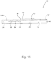
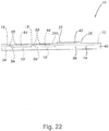
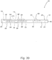
- the memory die stacks 18 may be arranged opposite one another so that the memory die stacks 18 are equally distributed on the component surface 24 and an opposing component surface 24A ( Figures 18-19 , 22-25 , 29-30 ), may be positioned on the component surface 24 only ( Figures 16-17 , 20-21 , 26-27 , and 31-32 ), or may be positioned on the opposing component surface 24A only ( Figure 28 ).
- any suitable location and distribution of memory die stacks 18 on the component surface 24 and the opposing component surface 24A may be utilized to achieve the desired performance of the device 10.
- the inclusion of the additional memory die stacks 18 provides additional data speed for the device 10.
- the use of two memory die stacks 18 increases the design from a two-channel to a four-channel operation, which approximately doubles the data speed.
- Figures 29-30 which include four memory die stacks 18 in a dual channel configuration (each memory die stack 18 having two dies 64), the design has an eight-channel operation, which approximate quadruples the data speed.
- an eight-channel operation may be achieved through the use of two memory die stacks 18 (with each memory die stack 18 having four dies 64) and a separate memory channel 70 for each die 64.
- the connectors 68 between each die 64 to the memory channel 70 may pass through the other dies 64 located between the die 64 and the memory channel 70.
- the dies 64 in each memory die stack 18 can be stacked onto each other in an overlapping arrangement to conserve space on the substrate 12.
- dies 64 and memory die stacks 18 may be used to achieve the desired data speed and compact design of the device 10.
Landscapes
- Engineering & Computer Science (AREA)
- Theoretical Computer Science (AREA)
- General Engineering & Computer Science (AREA)
- Physics & Mathematics (AREA)
- General Physics & Mathematics (AREA)
- Microelectronics & Electronic Packaging (AREA)
- Computer Hardware Design (AREA)
- Coupling Device And Connection With Printed Circuit (AREA)
- Devices For Indicating Variable Information By Combining Individual Elements (AREA)
- Combinations Of Printed Boards (AREA)
- Semiconductor Memories (AREA)
- Details Of Connecting Devices For Male And Female Coupling (AREA)
Claims (10)
- Périphérique de stockage externe comprenant :(a) un substrat (12) ;(b) un contrôleur (16) électriquement couplé au substrat ;(c) au moins un empilement de puces de mémoire (18) électriquement couplées au substrat ;(d) un connecteur (14) électriquement couplé au substrat ;(e) le périphérique de stockage externe étant configuré pour supporter au moins deux normes USB avec des interfaces qui sont mécaniquement différentes ;(f) le connecteur (14) comprenant des ressorts (52) et des pattes de connexion (20) électriquement couplés au substrat (12) ;
caractérisé en ce que(g) le connecteur (14) comprend un couvercle (32) ayant une pluralité d'ouvertures (44) positionnées adjacentes et/ou derrière les pattes de connexion (20) ;(h) chaque ressort (52) a une saillie de couplage (60) qui s'étend à travers chaque ouverture (44) lorsque les ressorts (52) sont dans une position non comprimée ;et en ce que les pattes de connexion (20) sont intégrées à l'intérieur du couvercle (32). - Périphérique de stockage externe selon la revendication 1, comprenant en outre une pluralité de points de couplage (28) montés sur la surface de connexion du substrat configurés pour être couplés à une barre de contact (22).
- Clé périphérique de stockage externe selon la revendication 2, la barre de contact (22) étant montée sur une surface de composant (24) du substrat (12).
- Périphérique de stockage externe selon la revendication 3, la barre de contact (22) étant sensiblement entourée par un boîtier externe (66) qui entoure le substrat (12).
- Périphérique de stockage externe selon la revendication 3, la barre de contact (22) comprenant en outre un couvercle (32).
- Périphérique de stockage externe selon l'une quelconque des revendications 1 à 5, l'au moins un empilement de puces de mémoire (18) étant monté sur une surface de composant (24) ou une surface de connexion (26) du substrat (12).
- Périphérique de stockage externe selon la revendication 6, comprenant en outre une pluralité d'empilements de puces de mémoire (18), au moins l'un de la pluralité d'empilements de puces de mémoire étant monté sur une surface de connexion (26) du substrat (12) et au moins l'un de la pluralité d'empilements de puces de mémoire étant monté sur une surface de composant (24) du substrat.
- Périphérique de stockage externe selon la revendication 7, chacun de la pluralité d'empilements de puces de mémoire (18) comprenant une pluralité de puces (64).
- Périphérique de stockage externe selon la revendication 8, la pluralité de puces (64) d'au moins deux de la pluralité d'empilements de puces de mémoire (18) étant stockées dans un agencement de chevauchement.
- Périphérique de stockage externe selon l'une quelconque des revendications 1 à 9, le périphérique de stockage externe (10) comprenant des surfaces sensiblement plates sur tous les côtés.
Priority Applications (2)
| Application Number | Priority Date | Filing Date | Title |
|---|---|---|---|
| EP18168629.6A EP3367517B3 (fr) | 2011-01-31 | 2012-01-31 | Périphérique de stockage externe |
| DK18168629.6T DK3367517T6 (da) | 2011-01-31 | 2012-01-31 | Eksternt lagermedie |
Applications Claiming Priority (4)
| Application Number | Priority Date | Filing Date | Title |
|---|---|---|---|
| US201161438123P | 2011-01-31 | 2011-01-31 | |
| US201161438140P | 2011-01-31 | 2011-01-31 | |
| US201161438139P | 2011-01-31 | 2011-01-31 | |
| US201161442379P | 2011-02-14 | 2011-02-14 |
Related Child Applications (2)
| Application Number | Title | Priority Date | Filing Date |
|---|---|---|---|
| EP18168629.6A Division EP3367517B3 (fr) | 2011-01-31 | 2012-01-31 | Périphérique de stockage externe |
| EP18168629.6A Division-Into EP3367517B3 (fr) | 2011-01-31 | 2012-01-31 | Périphérique de stockage externe |
Publications (3)
| Publication Number | Publication Date |
|---|---|
| EP2493033A2 EP2493033A2 (fr) | 2012-08-29 |
| EP2493033A3 EP2493033A3 (fr) | 2015-01-21 |
| EP2493033B1 true EP2493033B1 (fr) | 2018-05-30 |
Family
ID=45529016
Family Applications (4)
| Application Number | Title | Priority Date | Filing Date |
|---|---|---|---|
| EP12153257.6A Withdrawn EP2482391A3 (fr) | 2011-01-31 | 2012-01-31 | Connecteur pour plusieurs normes de connexion de l'interface |
| EP12153316.0A Withdrawn EP2511829A3 (fr) | 2011-01-31 | 2012-01-31 | Périphérique externe |
| EP12153313.7A Active EP2493033B1 (fr) | 2011-01-31 | 2012-01-31 | Périphérique de stockage externe |
| EP18168629.6A Active EP3367517B3 (fr) | 2011-01-31 | 2012-01-31 | Périphérique de stockage externe |
Family Applications Before (2)
| Application Number | Title | Priority Date | Filing Date |
|---|---|---|---|
| EP12153257.6A Withdrawn EP2482391A3 (fr) | 2011-01-31 | 2012-01-31 | Connecteur pour plusieurs normes de connexion de l'interface |
| EP12153316.0A Withdrawn EP2511829A3 (fr) | 2011-01-31 | 2012-01-31 | Périphérique externe |
Family Applications After (1)
| Application Number | Title | Priority Date | Filing Date |
|---|---|---|---|
| EP18168629.6A Active EP3367517B3 (fr) | 2011-01-31 | 2012-01-31 | Périphérique de stockage externe |
Country Status (4)
| Country | Link |
|---|---|
| EP (4) | EP2482391A3 (fr) |
| DK (2) | DK3367517T6 (fr) |
| ES (2) | ES2683697T3 (fr) |
| PT (2) | PT3367517T (fr) |
Families Citing this family (2)
| Publication number | Priority date | Publication date | Assignee | Title |
|---|---|---|---|---|
| CN111179979A (zh) * | 2019-12-20 | 2020-05-19 | 宜鼎国际股份有限公司 | 迭板构造 |
| CN111405753A (zh) * | 2020-03-30 | 2020-07-10 | 武汉光谷信息光电子创新中心有限公司 | 一种印刷电路板金手指的保护套 |
Family Cites Families (11)
| Publication number | Priority date | Publication date | Assignee | Title |
|---|---|---|---|---|
| US20080318449A1 (en) * | 1999-08-04 | 2008-12-25 | Super Talent Electronics, Inc. | MULTI-LEVEL CELL (MLC) DUAL PERSONALITY EXTENDED eSATA FLASH MEMORY DEVICE |
| US20050156333A1 (en) * | 2003-09-11 | 2005-07-21 | Super Talent Electronics Inc. | Narrow Universal-Serial-Bus (USB) Flash-Memory Card with Straight Sides using a Ball-Grid-Array (BGA) Chip |
| US7440286B2 (en) * | 2005-04-21 | 2008-10-21 | Super Talent Electronics, Inc. | Extended USB dual-personality card reader |
| US7872873B2 (en) * | 2003-12-02 | 2011-01-18 | Super Talent Electronics, Inc. | Extended COB-USB with dual-personality contacts |
| US7623354B2 (en) * | 2005-09-29 | 2009-11-24 | Kingston Technology Corporation | Folding USB drive |
| US20070112981A1 (en) * | 2005-11-15 | 2007-05-17 | Motorola, Inc. | Secure USB storage device |
| TW200935319A (en) * | 2008-04-11 | 2009-08-16 | Chant Sincere Co Ltd | A card reader |
| US8239581B2 (en) * | 2008-05-15 | 2012-08-07 | Seagate Technology Llc | Data storage device compatible with multiple interconnect standards |
| US20100203751A1 (en) * | 2009-02-10 | 2010-08-12 | Chou Hsien Tsai | Socket structure |
| TWM387417U (en) * | 2010-03-18 | 2010-08-21 | Power Quotient Int Co Ltd | USB connector |
| DE202010009523U1 (de) * | 2010-06-25 | 2010-11-11 | Shenzhen Oversea Win Technology Co., Ltd. | Verbundstecker |
-
2012
- 2012-01-31 EP EP12153257.6A patent/EP2482391A3/fr not_active Withdrawn
- 2012-01-31 DK DK18168629.6T patent/DK3367517T6/da active
- 2012-01-31 EP EP12153316.0A patent/EP2511829A3/fr not_active Withdrawn
- 2012-01-31 PT PT181686296T patent/PT3367517T/pt unknown
- 2012-01-31 ES ES12153313.7T patent/ES2683697T3/es active Active
- 2012-01-31 ES ES18168629T patent/ES2763279T7/es active Active
- 2012-01-31 EP EP12153313.7A patent/EP2493033B1/fr active Active
- 2012-01-31 EP EP18168629.6A patent/EP3367517B3/fr active Active
- 2012-01-31 PT PT121533137T patent/PT2493033T/pt unknown
- 2012-01-31 DK DK12153313.7T patent/DK2493033T3/en active
Non-Patent Citations (1)
| Title |
|---|
| None * |
Also Published As
| Publication number | Publication date |
|---|---|
| EP2511829A3 (fr) | 2014-09-24 |
| EP2511829A2 (fr) | 2012-10-17 |
| ES2763279T7 (es) | 2023-11-29 |
| DK3367517T3 (da) | 2020-01-02 |
| EP3367517B3 (fr) | 2023-06-21 |
| DK3367517T6 (da) | 2023-09-11 |
| DK2493033T3 (en) | 2018-09-03 |
| EP2493033A2 (fr) | 2012-08-29 |
| PT2493033T (pt) | 2018-07-26 |
| EP2482391A2 (fr) | 2012-08-01 |
| EP3367517B1 (fr) | 2019-09-18 |
| EP2482391A3 (fr) | 2013-12-04 |
| EP2493033A3 (fr) | 2015-01-21 |
| PT3367517T (pt) | 2019-12-04 |
| EP3367517A1 (fr) | 2018-08-29 |
| ES2763279T3 (es) | 2020-05-27 |
| ES2683697T3 (es) | 2018-09-27 |
Similar Documents
| Publication | Publication Date | Title |
|---|---|---|
| US8693206B2 (en) | External storage device | |
| US8523610B2 (en) | Connector for multiple interface connection standards | |
| US11637390B2 (en) | I/O connector configured for cable connection to a midboard | |
| US11870171B2 (en) | High-density edge connector | |
| US20140073174A1 (en) | Electrical connector | |
| US8979594B2 (en) | Electrical receptacle | |
| US20120071032A1 (en) | Electrical receptacle | |
| US20140073173A1 (en) | Electrical connector | |
| WO2011060236A1 (fr) | Connecteur à petit facteur de forme et haute performance | |
| CN102957013A (zh) | 线缆插头连接器、板端插座连接器及连接器组件 | |
| CN105098529B (zh) | 插座电连接器 | |
| US7467953B2 (en) | Cable connector assembly with improved coupler | |
| US7955138B1 (en) | Electrical connector with improved housing for staggering contact | |
| EP2493033B1 (fr) | Périphérique de stockage externe | |
| JP3511134B2 (ja) | 積み重ね式カードエッジコネクタ | |
| TWI358173B (en) | Card connector and assembly of the same | |
| JP4387943B2 (ja) | 相互接続システム | |
| CN117121305A (zh) | 用于高功率计算系统的电连接器 | |
| CN114208404A (zh) | 卡边缘连接器系统 | |
| US11984678B2 (en) | I/O connector configured for cable connection to a midboard | |
| KR101330557B1 (ko) | 전기 커넥터 |
Legal Events
| Date | Code | Title | Description |
|---|---|---|---|
| PUAI | Public reference made under article 153(3) epc to a published international application that has entered the european phase |
Free format text: ORIGINAL CODE: 0009012 |
|
| AK | Designated contracting states |
Kind code of ref document: A2 Designated state(s): AL AT BE BG CH CY CZ DE DK EE ES FI FR GB GR HR HU IE IS IT LI LT LU LV MC MK MT NL NO PL PT RO RS SE SI SK SM TR |
|
| AX | Request for extension of the european patent |
Extension state: BA ME |
|
| PUAL | Search report despatched |
Free format text: ORIGINAL CODE: 0009013 |
|
| AK | Designated contracting states |
Kind code of ref document: A3 Designated state(s): AL AT BE BG CH CY CZ DE DK EE ES FI FR GB GR HR HU IE IS IT LI LT LU LV MC MK MT NL NO PL PT RO RS SE SI SK SM TR |
|
| AX | Request for extension of the european patent |
Extension state: BA ME |
|
| RIC1 | Information provided on ipc code assigned before grant |
Ipc: H01R 24/62 20110101AFI20141218BHEP Ipc: H01R 27/00 20060101ALI20141218BHEP |
|
| 17P | Request for examination filed |
Effective date: 20150721 |
|
| RBV | Designated contracting states (corrected) |
Designated state(s): AL AT BE BG CH CY CZ DE DK EE ES FI FR GB GR HR HU IE IS IT LI LT LU LV MC MK MT NL NO PL PT RO RS SE SI SK SM TR |
|
| STAA | Information on the status of an ep patent application or granted ep patent |
Free format text: STATUS: EXAMINATION IS IN PROGRESS |
|
| 17Q | First examination report despatched |
Effective date: 20170628 |
|
| GRAP | Despatch of communication of intention to grant a patent |
Free format text: ORIGINAL CODE: EPIDOSNIGR1 |
|
| STAA | Information on the status of an ep patent application or granted ep patent |
Free format text: STATUS: GRANT OF PATENT IS INTENDED |
|
| INTG | Intention to grant announced |
Effective date: 20171220 |
|
| GRAS | Grant fee paid |
Free format text: ORIGINAL CODE: EPIDOSNIGR3 |
|
| GRAA | (expected) grant |
Free format text: ORIGINAL CODE: 0009210 |
|
| STAA | Information on the status of an ep patent application or granted ep patent |
Free format text: STATUS: THE PATENT HAS BEEN GRANTED |
|
| AK | Designated contracting states |
Kind code of ref document: B1 Designated state(s): AL AT BE BG CH CY CZ DE DK EE ES FI FR GB GR HR HU IE IS IT LI LT LU LV MC MK MT NL NO PL PT RO RS SE SI SK SM TR |
|
| REG | Reference to a national code |
Ref country code: GB Ref legal event code: FG4D |
|
| REG | Reference to a national code |
Ref country code: CH Ref legal event code: EP |
|
| REG | Reference to a national code |
Ref country code: AT Ref legal event code: REF Ref document number: 1004573 Country of ref document: AT Kind code of ref document: T Effective date: 20180615 |
|
| REG | Reference to a national code |
Ref country code: IE Ref legal event code: FG4D |
|
| REG | Reference to a national code |
Ref country code: DE Ref legal event code: R096 Ref document number: 602012046787 Country of ref document: DE |
|
| REG | Reference to a national code |
Ref country code: PT Ref legal event code: SC4A Ref document number: 2493033 Country of ref document: PT Date of ref document: 20180726 Kind code of ref document: T Free format text: AVAILABILITY OF NATIONAL TRANSLATION Effective date: 20180719 |
|
| REG | Reference to a national code |
Ref country code: CH Ref legal event code: NV Representative=s name: R.A. EGLI AND CO, PATENTANWAELTE, CH |
|
| REG | Reference to a national code |
Ref country code: DK Ref legal event code: T3 Effective date: 20180829 |
|
| REG | Reference to a national code |
Ref country code: NL Ref legal event code: FP |
|
| REG | Reference to a national code |
Ref country code: SE Ref legal event code: TRGR |
|
| REG | Reference to a national code |
Ref country code: ES Ref legal event code: FG2A Ref document number: 2683697 Country of ref document: ES Kind code of ref document: T3 Effective date: 20180927 |
|
| REG | Reference to a national code |
Ref country code: LT Ref legal event code: MG4D |
|
| PG25 | Lapsed in a contracting state [announced via postgrant information from national office to epo] |
Ref country code: BG Free format text: LAPSE BECAUSE OF FAILURE TO SUBMIT A TRANSLATION OF THE DESCRIPTION OR TO PAY THE FEE WITHIN THE PRESCRIBED TIME-LIMIT Effective date: 20180830 Ref country code: NO Free format text: LAPSE BECAUSE OF FAILURE TO SUBMIT A TRANSLATION OF THE DESCRIPTION OR TO PAY THE FEE WITHIN THE PRESCRIBED TIME-LIMIT Effective date: 20180830 Ref country code: FI Free format text: LAPSE BECAUSE OF FAILURE TO SUBMIT A TRANSLATION OF THE DESCRIPTION OR TO PAY THE FEE WITHIN THE PRESCRIBED TIME-LIMIT Effective date: 20180530 Ref country code: CY Free format text: LAPSE BECAUSE OF FAILURE TO SUBMIT A TRANSLATION OF THE DESCRIPTION OR TO PAY THE FEE WITHIN THE PRESCRIBED TIME-LIMIT Effective date: 20180530 Ref country code: LT Free format text: LAPSE BECAUSE OF FAILURE TO SUBMIT A TRANSLATION OF THE DESCRIPTION OR TO PAY THE FEE WITHIN THE PRESCRIBED TIME-LIMIT Effective date: 20180530 |
|
| PG25 | Lapsed in a contracting state [announced via postgrant information from national office to epo] |
Ref country code: HR Free format text: LAPSE BECAUSE OF FAILURE TO SUBMIT A TRANSLATION OF THE DESCRIPTION OR TO PAY THE FEE WITHIN THE PRESCRIBED TIME-LIMIT Effective date: 20180530 Ref country code: LV Free format text: LAPSE BECAUSE OF FAILURE TO SUBMIT A TRANSLATION OF THE DESCRIPTION OR TO PAY THE FEE WITHIN THE PRESCRIBED TIME-LIMIT Effective date: 20180530 Ref country code: GR Free format text: LAPSE BECAUSE OF FAILURE TO SUBMIT A TRANSLATION OF THE DESCRIPTION OR TO PAY THE FEE WITHIN THE PRESCRIBED TIME-LIMIT Effective date: 20180831 Ref country code: RS Free format text: LAPSE BECAUSE OF FAILURE TO SUBMIT A TRANSLATION OF THE DESCRIPTION OR TO PAY THE FEE WITHIN THE PRESCRIBED TIME-LIMIT Effective date: 20180530 |
|
| PG25 | Lapsed in a contracting state [announced via postgrant information from national office to epo] |
Ref country code: EE Free format text: LAPSE BECAUSE OF FAILURE TO SUBMIT A TRANSLATION OF THE DESCRIPTION OR TO PAY THE FEE WITHIN THE PRESCRIBED TIME-LIMIT Effective date: 20180530 Ref country code: PL Free format text: LAPSE BECAUSE OF FAILURE TO SUBMIT A TRANSLATION OF THE DESCRIPTION OR TO PAY THE FEE WITHIN THE PRESCRIBED TIME-LIMIT Effective date: 20180530 Ref country code: RO Free format text: LAPSE BECAUSE OF FAILURE TO SUBMIT A TRANSLATION OF THE DESCRIPTION OR TO PAY THE FEE WITHIN THE PRESCRIBED TIME-LIMIT Effective date: 20180530 Ref country code: CZ Free format text: LAPSE BECAUSE OF FAILURE TO SUBMIT A TRANSLATION OF THE DESCRIPTION OR TO PAY THE FEE WITHIN THE PRESCRIBED TIME-LIMIT Effective date: 20180530 Ref country code: SK Free format text: LAPSE BECAUSE OF FAILURE TO SUBMIT A TRANSLATION OF THE DESCRIPTION OR TO PAY THE FEE WITHIN THE PRESCRIBED TIME-LIMIT Effective date: 20180530 |
|
| PG25 | Lapsed in a contracting state [announced via postgrant information from national office to epo] |
Ref country code: SM Free format text: LAPSE BECAUSE OF FAILURE TO SUBMIT A TRANSLATION OF THE DESCRIPTION OR TO PAY THE FEE WITHIN THE PRESCRIBED TIME-LIMIT Effective date: 20180530 |
|
| REG | Reference to a national code |
Ref country code: DE Ref legal event code: R097 Ref document number: 602012046787 Country of ref document: DE |
|
| PLBE | No opposition filed within time limit |
Free format text: ORIGINAL CODE: 0009261 |
|
| STAA | Information on the status of an ep patent application or granted ep patent |
Free format text: STATUS: NO OPPOSITION FILED WITHIN TIME LIMIT |
|
| 26N | No opposition filed |
Effective date: 20190301 |
|
| PG25 | Lapsed in a contracting state [announced via postgrant information from national office to epo] |
Ref country code: SI Free format text: LAPSE BECAUSE OF FAILURE TO SUBMIT A TRANSLATION OF THE DESCRIPTION OR TO PAY THE FEE WITHIN THE PRESCRIBED TIME-LIMIT Effective date: 20180530 |
|
| REG | Reference to a national code |
Ref country code: AT Ref legal event code: UEP Ref document number: 1004573 Country of ref document: AT Kind code of ref document: T Effective date: 20180530 |
|
| PG25 | Lapsed in a contracting state [announced via postgrant information from national office to epo] |
Ref country code: MC Free format text: LAPSE BECAUSE OF FAILURE TO SUBMIT A TRANSLATION OF THE DESCRIPTION OR TO PAY THE FEE WITHIN THE PRESCRIBED TIME-LIMIT Effective date: 20180530 |
|
| PG25 | Lapsed in a contracting state [announced via postgrant information from national office to epo] |
Ref country code: LU Free format text: LAPSE BECAUSE OF NON-PAYMENT OF DUE FEES Effective date: 20190131 |
|
| PG25 | Lapsed in a contracting state [announced via postgrant information from national office to epo] |
Ref country code: AL Free format text: LAPSE BECAUSE OF FAILURE TO SUBMIT A TRANSLATION OF THE DESCRIPTION OR TO PAY THE FEE WITHIN THE PRESCRIBED TIME-LIMIT Effective date: 20180530 |
|
| PG25 | Lapsed in a contracting state [announced via postgrant information from national office to epo] |
Ref country code: TR Free format text: LAPSE BECAUSE OF FAILURE TO SUBMIT A TRANSLATION OF THE DESCRIPTION OR TO PAY THE FEE WITHIN THE PRESCRIBED TIME-LIMIT Effective date: 20180530 |
|
| PG25 | Lapsed in a contracting state [announced via postgrant information from national office to epo] |
Ref country code: MT Free format text: LAPSE BECAUSE OF NON-PAYMENT OF DUE FEES Effective date: 20190131 |
|
| PG25 | Lapsed in a contracting state [announced via postgrant information from national office to epo] |
Ref country code: IS Free format text: LAPSE BECAUSE OF FAILURE TO SUBMIT A TRANSLATION OF THE DESCRIPTION OR TO PAY THE FEE WITHIN THE PRESCRIBED TIME-LIMIT Effective date: 20180930 |
|
| PG25 | Lapsed in a contracting state [announced via postgrant information from national office to epo] |
Ref country code: HU Free format text: LAPSE BECAUSE OF FAILURE TO SUBMIT A TRANSLATION OF THE DESCRIPTION OR TO PAY THE FEE WITHIN THE PRESCRIBED TIME-LIMIT; INVALID AB INITIO Effective date: 20120131 |
|
| PG25 | Lapsed in a contracting state [announced via postgrant information from national office to epo] |
Ref country code: MK Free format text: LAPSE BECAUSE OF FAILURE TO SUBMIT A TRANSLATION OF THE DESCRIPTION OR TO PAY THE FEE WITHIN THE PRESCRIBED TIME-LIMIT Effective date: 20180530 |
|
| REG | Reference to a national code |
Ref country code: DE Ref legal event code: R081 Ref document number: 602012046787 Country of ref document: DE Owner name: ROCKPATECH AG, CH Free format text: FORMER OWNER: KUSTER, MARTIN, WALCHWILL, CH Ref country code: DE Ref legal event code: R082 Ref document number: 602012046787 Country of ref document: DE Representative=s name: TER MEER STEINMEISTER & PARTNER PATENTANWAELTE, DE |
|
| PGFP | Annual fee paid to national office [announced via postgrant information from national office to epo] |
Ref country code: IE Payment date: 20230119 Year of fee payment: 12 Ref country code: FR Payment date: 20230123 Year of fee payment: 12 Ref country code: ES Payment date: 20230216 Year of fee payment: 12 Ref country code: DK Payment date: 20230123 Year of fee payment: 12 Ref country code: CH Payment date: 20230130 Year of fee payment: 12 Ref country code: AT Payment date: 20230118 Year of fee payment: 12 |
|
| PGFP | Annual fee paid to national office [announced via postgrant information from national office to epo] |
Ref country code: SE Payment date: 20230123 Year of fee payment: 12 Ref country code: IT Payment date: 20230131 Year of fee payment: 12 Ref country code: BE Payment date: 20230123 Year of fee payment: 12 |
|
| P01 | Opt-out of the competence of the unified patent court (upc) registered |
Effective date: 20230421 |
|
| P02 | Opt-out of the competence of the unified patent court (upc) changed |
Effective date: 20230515 |
|
| REG | Reference to a national code |
Ref country code: AT Ref legal event code: PC Ref document number: 1004573 Country of ref document: AT Kind code of ref document: T Owner name: ROCKPATECH AG, CH Effective date: 20230929 |
|
| REG | Reference to a national code |
Ref country code: DE Ref legal event code: R039 Ref document number: 602012046787 Country of ref document: DE Ref country code: DE Ref legal event code: R008 Ref document number: 602012046787 Country of ref document: DE |
|
| PGFP | Annual fee paid to national office [announced via postgrant information from national office to epo] |
Ref country code: NL Payment date: 20240123 Year of fee payment: 13 |
|
| PGFP | Annual fee paid to national office [announced via postgrant information from national office to epo] |
Ref country code: IE Payment date: 20240118 Year of fee payment: 13 Ref country code: ES Payment date: 20240216 Year of fee payment: 13 |
|
| PGFP | Annual fee paid to national office [announced via postgrant information from national office to epo] |
Ref country code: AT Payment date: 20240118 Year of fee payment: 13 |
|
| PGFP | Annual fee paid to national office [announced via postgrant information from national office to epo] |
Ref country code: DE Payment date: 20240129 Year of fee payment: 13 Ref country code: GB Payment date: 20240124 Year of fee payment: 13 Ref country code: PT Payment date: 20240119 Year of fee payment: 13 Ref country code: CH Payment date: 20240201 Year of fee payment: 13 |