EP2492997A1 - Bipolar plate for fuel cell - Google Patents
Bipolar plate for fuel cell Download PDFInfo
- Publication number
- EP2492997A1 EP2492997A1 EP11762000A EP11762000A EP2492997A1 EP 2492997 A1 EP2492997 A1 EP 2492997A1 EP 11762000 A EP11762000 A EP 11762000A EP 11762000 A EP11762000 A EP 11762000A EP 2492997 A1 EP2492997 A1 EP 2492997A1
- Authority
- EP
- European Patent Office
- Prior art keywords
- electrochemical reaction
- reaction region
- bipolar plate
- fuel cell
- jointing
- Prior art date
- Legal status (The legal status is an assumption and is not a legal conclusion. Google has not performed a legal analysis and makes no representation as to the accuracy of the status listed.)
- Granted
Links
Images

Classifications
-
- H—ELECTRICITY
- H01—ELECTRIC ELEMENTS
- H01M—PROCESSES OR MEANS, e.g. BATTERIES, FOR THE DIRECT CONVERSION OF CHEMICAL ENERGY INTO ELECTRICAL ENERGY
- H01M8/00—Fuel cells; Manufacture thereof
- H01M8/02—Details
- H01M8/0202—Collectors; Separators, e.g. bipolar separators; Interconnectors
- H01M8/0204—Non-porous and characterised by the material
- H01M8/0221—Organic resins; Organic polymers
-
- H—ELECTRICITY
- H01—ELECTRIC ELEMENTS
- H01M—PROCESSES OR MEANS, e.g. BATTERIES, FOR THE DIRECT CONVERSION OF CHEMICAL ENERGY INTO ELECTRICAL ENERGY
- H01M8/00—Fuel cells; Manufacture thereof
- H01M8/02—Details
- H01M8/0271—Sealing or supporting means around electrodes, matrices or membranes
-
- H—ELECTRICITY
- H01—ELECTRIC ELEMENTS
- H01M—PROCESSES OR MEANS, e.g. BATTERIES, FOR THE DIRECT CONVERSION OF CHEMICAL ENERGY INTO ELECTRICAL ENERGY
- H01M8/00—Fuel cells; Manufacture thereof
- H01M8/02—Details
- H01M8/0271—Sealing or supporting means around electrodes, matrices or membranes
- H01M8/0273—Sealing or supporting means around electrodes, matrices or membranes with sealing or supporting means in the form of a frame
-
- H—ELECTRICITY
- H01—ELECTRIC ELEMENTS
- H01M—PROCESSES OR MEANS, e.g. BATTERIES, FOR THE DIRECT CONVERSION OF CHEMICAL ENERGY INTO ELECTRICAL ENERGY
- H01M8/00—Fuel cells; Manufacture thereof
- H01M8/02—Details
- H01M8/0271—Sealing or supporting means around electrodes, matrices or membranes
- H01M8/0286—Processes for forming seals
-
- H—ELECTRICITY
- H01—ELECTRIC ELEMENTS
- H01M—PROCESSES OR MEANS, e.g. BATTERIES, FOR THE DIRECT CONVERSION OF CHEMICAL ENERGY INTO ELECTRICAL ENERGY
- H01M8/00—Fuel cells; Manufacture thereof
- H01M8/10—Fuel cells with solid electrolytes
- H01M2008/1095—Fuel cells with polymeric electrolytes
-
- H—ELECTRICITY
- H01—ELECTRIC ELEMENTS
- H01M—PROCESSES OR MEANS, e.g. BATTERIES, FOR THE DIRECT CONVERSION OF CHEMICAL ENERGY INTO ELECTRICAL ENERGY
- H01M8/00—Fuel cells; Manufacture thereof
- H01M8/24—Grouping of fuel cells, e.g. stacking of fuel cells
- H01M8/241—Grouping of fuel cells, e.g. stacking of fuel cells with solid or matrix-supported electrolytes
- H01M8/242—Grouping of fuel cells, e.g. stacking of fuel cells with solid or matrix-supported electrolytes comprising framed electrodes or intermediary frame-like gaskets
-
- Y—GENERAL TAGGING OF NEW TECHNOLOGICAL DEVELOPMENTS; GENERAL TAGGING OF CROSS-SECTIONAL TECHNOLOGIES SPANNING OVER SEVERAL SECTIONS OF THE IPC; TECHNICAL SUBJECTS COVERED BY FORMER USPC CROSS-REFERENCE ART COLLECTIONS [XRACs] AND DIGESTS
- Y02—TECHNOLOGIES OR APPLICATIONS FOR MITIGATION OR ADAPTATION AGAINST CLIMATE CHANGE
- Y02E—REDUCTION OF GREENHOUSE GAS [GHG] EMISSIONS, RELATED TO ENERGY GENERATION, TRANSMISSION OR DISTRIBUTION
- Y02E60/00—Enabling technologies; Technologies with a potential or indirect contribution to GHG emissions mitigation
- Y02E60/30—Hydrogen technology
- Y02E60/50—Fuel cells
-
- Y—GENERAL TAGGING OF NEW TECHNOLOGICAL DEVELOPMENTS; GENERAL TAGGING OF CROSS-SECTIONAL TECHNOLOGIES SPANNING OVER SEVERAL SECTIONS OF THE IPC; TECHNICAL SUBJECTS COVERED BY FORMER USPC CROSS-REFERENCE ART COLLECTIONS [XRACs] AND DIGESTS
- Y02—TECHNOLOGIES OR APPLICATIONS FOR MITIGATION OR ADAPTATION AGAINST CLIMATE CHANGE
- Y02P—CLIMATE CHANGE MITIGATION TECHNOLOGIES IN THE PRODUCTION OR PROCESSING OF GOODS
- Y02P70/00—Climate change mitigation technologies in the production process for final industrial or consumer products
- Y02P70/50—Manufacturing or production processes characterised by the final manufactured product
Definitions
- the invention belongs to the technical field of fuel cell, and more particularly, relates to a bipolar plate for fuel cell.
- Fuel cell is typically composed of a plurality of cell units with each comprising two electrodes (anode and cathode), these two electrodes are separated from each other by an electrolyte element and assembled with each other in series to form a fuel cell stack.
- Electrochemical reaction is implemented by supplying proper reactants to each electrode, i.e. supplying fuel to one electrode and oxidant to the other electrode, as a result, potential difference is formed between the electrodes and accordingly, electric energy is generated.
- bipolar plate In order to supply reactants to each electrode, a particular interfacial element which is usually known as "bipolar plate" and disposed at two sides each individual cell is used.
- the bipolar plate is usually in the form of individual element disposed in the vicinity of anode or cathode support body.
- the bipolar plate is a key element for fuel cell pack.
- the bipolar plates perform the following functions for the purpose of maintaining the optimal working state and service life of the fuel cell stack: (1) electrical conductor of cell, cathode and anode are formed at the two sides of the bipolar plate respectively, thus plenty of cell units are connected in series to form the fuel cell stack; (2) reaction gas (mass transfer) is supplied to the electrodes through channels; (3) managements for water and heat are coordinated so as to prevent medium cooling and leakage of reaction gas; and (4) structural strength support is offered to membrane electrode assembly (MEA).
- MEA membrane electrode assembly
- the material of the bipolar plate requires high electrical conductivity, sufficient mechanical strength, excellent thermal conductivity, low air permeability and corrosion resistance, and is capable of being chemically stable in a working environment of cell for a quite long time. Furthermore, in view of the requirements on design as well as processing and manufacturing easiness, the material of the bipolar plate should also have the features of light weight, small size, low cost, and even recyclability, etc.
- the material adopted must be electrochemical corrosion-resistant and superior in structural strength and stability owing to the electrochemical reaction working environment of fuel cell. Hence, factors in all respects must be taken into full consideration when a high-performance bipolar plate for cell is designed.
- the materials of the bipolar plate for cell include: carbon plate, metal plate and the like.
- carbon plate as polar plate for cell is attributed to its good electrical conductivity, heat transfer property and corrosion resistance.
- metal plate lies in its excellent electrical conductivity, structural strength and formability and in the fact that it is still a good material of electrode plate even after anti-corrosion surface treatment.
- the objective of the invention is to provide a bipolar plate for fuel cell in order to optimize the design of current bipolar plate for fuel cell.
- the electrochemical reaction region is located centrally, and the non-electrochemical reaction region is located around the electrochemical reaction region.
- the non-electrochemical reaction region is made of a non-conductive material.
- the material density of the non-electrochemical reaction region is 0.1 to 1.5g/cm 3 .
- non-electrochemical reaction region is provided with a reactant conveying passage.
- the non-electrochemical reaction region is provided with mounting holes.
- a part of the electrochemical reaction region for jointing with the non-electrochemical reaction region is connected with a corresponding jointing part of the non-electrochemical reaction region in an adhesive manner.
- a part of the electrochemical reaction region for jointing with the non-electrochemical reaction region is connected with a corresponding jointing part of the non-electrochemical reaction region in a squeezing manner.
- a part of the electrochemical reaction region for jointing with the non-electrochemical reaction region is connected with a corresponding jointing part of the non-electrochemical reaction region in a hot-pressing manner.
- a part of the electrochemical reaction region for jointing with the non-electrochemical reaction region is step-shaped, and a jointing part of the non-electrochemical reaction region is reverse step-shaped correspondingly.
- a part of the electrochemical reaction region for jointing with the non-electrochemical reaction region is saw tooth-shaped, and a jointing part of the non-electrochemical reaction region is reverse saw tooth-shaped correspondingly.
- a part of the electrochemical reaction region for jointing with the non-electrochemical reaction region is one or more than one protrusions, and a jointing part of the non-electrochemical reaction region is one or more than one corresponding grooves.
- a part of the electrochemical reaction region for jointing with the non-electrochemical reaction region is one or more than one grooves, and a jointing part of the non-electrochemical reaction region is one or more than one corresponding protrusions.
- jointing sidewalls of the electrochemical reaction region and the non-electrochemical reaction region are correspondingly provided with an annular groove respectively, and the annular groove is internally provided with an annular sealing strip.
- electrochemical reaction region and the non-electrochemical reaction region have the same thickness.
- the bipolar plate for fuel cell is divided into the electrochemical reaction region and the non-electrochemical reaction region that are combined and jointed to form the entire bipolar plate, and a new fuel cell is manufactured by laminating such bipolar plates.
- the design of this bipolar plate for fuel cell optimizes the conductivity of bipolar plate, reduces the loss, enhances the efficiency, and simultaneously lowers the material cost and simplifies the manufacturing complexity.
- a bipolar plate for fuel cell comprises an electrochemical reaction region 1 and a non-electrochemical reaction region 2 that are jointed with each other.
- the electrochemical reaction region 1 of the bipolar plate 10 is an region where fuel supplied reacts with oxidant, this region is corresponding to a proton exchange membrane, and to the parts on the bipolar plate which come into direct contact with the proton exchange membrane, such as channel and gas diffusion layer, and generally, the proton exchange membrane is further provided with a catalyst coating.
- the non-electrochemical reaction region 2 is an region where no electrochemical reaction occurs. The non-electrochemical reaction region 2 is used for supporting the electrochemical reaction region 1 and withstanding external acting forces.
- the electrochemical reaction regions 1 and the non- electrochemical reaction region 2 of the bipolar plate are divided in design, which could reduce design difficulty.
- the material for the bipolar plate in the electrochemical reaction region 1 may be materials that meet the demands of the bipolar plate for fuel cell, e.g. carbon plate, metal plate and the like.
- the material for the bipolar plate in the non-electrochemical reaction region 2 may be materials with certain strength and heat resistance, low cost and easy machining and formation. These two regions can be recovered respectively and then reused even if the electrochemical reaction region 1 becomes ineffective. As a result, fuel cell stack becomes more environment-friendly.
- the non-electrochemical reaction region 2 is made of a non-conductive material, such as ABS (styrene-butadiene-acrylonitrile-based ternary copolymer), PVC (polyvinyl chloride) and other insulating materials, and particularly, some materials with small density can be used for this region, for example, the material density of the non-electrochemical reaction region 2 is 0.1 to 1.5g/cm 3 , those skilled in this art could flexibly select the material of this region as required, and the non-electrochemical reaction region can support the electrochemical reaction region 1, withstand external acting forces and be insulating only if the material meets the demands on the performances of material for this region in the invention.
- ABS styrene-butadiene-acrylonitrile-based ternary copolymer
- PVC polyvinyl chloride
- both the reaction region and the non-reaction region at the periphery thereof are made of the same or similar conductive material, causing that a part of current generated by reaction passes through the non-reaction region at the periphery of the reaction region to form eddy current, as a result, gradient deviation of current and loss of current could be caused, and this disadvantageous current distribution is possibly liable to result in the shortening of the service life of fuel cell stack and even the occurrence of current short circuit.
- the electrochemical reaction region 1 and the non-electrochemical reaction region 2 of the bipolar plate are separated in design and insulating materials are used for fabiration of the non-electrochemical reaction region 2, so current could pass through the electrochemical reaction region 2 uniformly to avoid the generation of eddy current and improve the service life of fuel cell, prevent the occurrence of current short circuit and enhance the application safety of fuel cell.
- electrochemical reaction region is at the center position of the bipolar plate.
- the non-electrochemical reaction region is located around the electrochemical reaction region.
- the non-electrochemical reaction region 2 is provided with a reactant conveying passage 4 connected to channels of the electrochemical reaction region 1.
- the conveying passage 4 is used for conveying reactant of the electrochemical reaction region 1.
- the specific communication way and structure between the conveying passage 4 and the channel of the non-electrochemical reaction region 2 may be achieved by a number of techniques in prior art of bipolar plate designs, so detailed description regarding this part is herein omitted.
- the non-electrochemical reaction region 2 is provided with mounting holes 3 for the assembly of fuel cell stack.
- the bipolar plate for fuel cell provided by the invention is lower in cost since no reaction occurs in the non-electrochemical reaction region 2 and the material of this region is convenient for forming and machining, so the total weight of the materials of fuel cell is reduced dramatically as well, the worry about damage to the bipolar plate during assembly is avoided, and the assembly requirement of fuel cell stack is lessened.
- the part of the electrochemical reaction region 1 for jointing with the non-electrochemical reaction region 2 may be achieved in a number of approaches, such as jointing subsequent to adhesion, hot pressing and squeezing, etc.
- FIG.2 is an A-A sectional view of FIG.1 , in FIG.2 , the part of the electrochemical reaction region 1 for jointing with the non-electrochemical reaction region 2 is step-shaped, and the jointing part of the non-electrochemical reaction region 2 is reverse step-shaped correspondingly.
- FIG.3 is an A-A sectional view of FIG.1 , in FIG.3 , the part of the electrochemical reaction region 1 for jointing with the non-electrochemical reaction region 2 is saw tooth-shaped, and the jointing part of the non-electrochemical reaction region 2 is reverse saw tooth-shaped correspondingly.
- FIG.4 is an A-A sectional view of FIG.1 , in FIG.4 , the part of the electrochemical reaction region 1 for jointing with the non-electrochemical reaction region 2 is one or more than one protrusions, and the jointing part of the non-electrochemical reaction region 2 is one or more than one corresponding grooves.
- the part of the electrochemical reaction region 1 for jointing with the non-electrochemical reaction region 2 is one or more than one grooves, and the jointing part of the non-electrochemical reaction region 2 is one or more than one corresponding protrusions.
- FIG.5 is an A-A sectional view of FIG.1 , in FIG.5 , the jointing sidewalls of the electrochemical reaction region 1 and the non-electrochemical reaction region 2 are correspondingly provided with an annular groove respectively, and the annular groove is internally provided with an annular sealing strip 5.
- the sealing of the jointing parts at the sealing strips 5 is realized by the sealing strips 5.
- the annular sealing strips 5 can be embedded in the annular grooves of the electrochemical reaction region 1 at first, and then the electrochemical reaction region 1 is pressed into the non-electrochemical reaction region 2.
Abstract
Description
- The invention belongs to the technical field of fuel cell, and more particularly, relates to a bipolar plate for fuel cell.
- Fuel cell is typically composed of a plurality of cell units with each comprising two electrodes (anode and cathode), these two electrodes are separated from each other by an electrolyte element and assembled with each other in series to form a fuel cell stack. Electrochemical reaction is implemented by supplying proper reactants to each electrode, i.e. supplying fuel to one electrode and oxidant to the other electrode, as a result, potential difference is formed between the electrodes and accordingly, electric energy is generated.
- In order to supply reactants to each electrode, a particular interfacial element which is usually known as "bipolar plate" and disposed at two sides each individual cell is used. The bipolar plate is usually in the form of individual element disposed in the vicinity of anode or cathode support body. The bipolar plate is a key element for fuel cell pack. In the operating process of the fuel cell stack, the bipolar plates perform the following functions for the purpose of maintaining the optimal working state and service life of the fuel cell stack: (1) electrical conductor of cell, cathode and anode are formed at the two sides of the bipolar plate respectively, thus plenty of cell units are connected in series to form the fuel cell stack; (2) reaction gas (mass transfer) is supplied to the electrodes through channels; (3) managements for water and heat are coordinated so as to prevent medium cooling and leakage of reaction gas; and (4) structural strength support is offered to membrane electrode assembly (MEA).
- To perform the functions above, the material of the bipolar plate requires high electrical conductivity, sufficient mechanical strength, excellent thermal conductivity, low air permeability and corrosion resistance, and is capable of being chemically stable in a working environment of cell for a quite long time. Furthermore, in view of the requirements on design as well as processing and manufacturing easiness, the material of the bipolar plate should also have the features of light weight, small size, low cost, and even recyclability, etc.
- The material adopted must be electrochemical corrosion-resistant and superior in structural strength and stability owing to the electrochemical reaction working environment of fuel cell. Hence, factors in all respects must be taken into full consideration when a high-performance bipolar plate for cell is designed. Typically, the materials of the bipolar plate for cell include: carbon plate, metal plate and the like. Traditionally, the use of carbon plate as polar plate for cell is attributed to its good electrical conductivity, heat transfer property and corrosion resistance. And the reason for using metal plate lies in its excellent electrical conductivity, structural strength and formability and in the fact that it is still a good material of electrode plate even after anti-corrosion surface treatment.
- In addition, considering that the manufacturing cost of polar plate for cell is high, to lower the cost of fuel cell, one of the attempting directions in fuel cell's design is to seek for the design and manufacturing method for optimizing the bipolar plate for cell.
- The objective of the invention is to provide a bipolar plate for fuel cell in order to optimize the design of current bipolar plate for fuel cell.
- The objective of the invention is implemented through the technical proposal as follows:
- A bipolar plate for fuel cell comprises an electrochemical reaction region and a non-electrochemical reaction region that are jointed with each other.
- Further, the electrochemical reaction region is located centrally, and the non-electrochemical reaction region is located around the electrochemical reaction region.
- Further, the non-electrochemical reaction region is made of a non-conductive material.
- Further, the material density of the non-electrochemical reaction region is 0.1 to 1.5g/cm3.
- Further, the non-electrochemical reaction region is provided with a reactant conveying passage.
- Further, the non-electrochemical reaction region is provided with mounting holes.
- Further, a part of the electrochemical reaction region for jointing with the non-electrochemical reaction region is connected with a corresponding jointing part of the non-electrochemical reaction region in an adhesive manner.
- Further, a part of the electrochemical reaction region for jointing with the non-electrochemical reaction region is connected with a corresponding jointing part of the non-electrochemical reaction region in a squeezing manner.
- Further, a part of the electrochemical reaction region for jointing with the non-electrochemical reaction region is connected with a corresponding jointing part of the non-electrochemical reaction region in a hot-pressing manner.
- Further, a part of the electrochemical reaction region for jointing with the non-electrochemical reaction region is step-shaped, and a jointing part of the non-electrochemical reaction region is reverse step-shaped correspondingly.
- Further, a part of the electrochemical reaction region for jointing with the non-electrochemical reaction region is saw tooth-shaped, and a jointing part of the non-electrochemical reaction region is reverse saw tooth-shaped correspondingly.
- Further, a part of the electrochemical reaction region for jointing with the non-electrochemical reaction region is one or more than one protrusions, and a jointing part of the non-electrochemical reaction region is one or more than one corresponding grooves.
- Further, a part of the electrochemical reaction region for jointing with the non-electrochemical reaction region is one or more than one grooves, and a jointing part of the non-electrochemical reaction region is one or more than one corresponding protrusions.
- Further, the jointing sidewalls of the electrochemical reaction region and the non-electrochemical reaction region are correspondingly provided with an annular groove respectively, and the annular groove is internally provided with an annular sealing strip.
- Further, the electrochemical reaction region and the non-electrochemical reaction region have the same thickness.
- In the invention, the bipolar plate for fuel cell is divided into the electrochemical reaction region and the non-electrochemical reaction region that are combined and jointed to form the entire bipolar plate, and a new fuel cell is manufactured by laminating such bipolar plates. The design of this bipolar plate for fuel cell optimizes the conductivity of bipolar plate, reduces the loss, enhances the efficiency, and simultaneously lowers the material cost and simplifies the manufacturing complexity.
- Further description is made below to the invention with reference to the drawings and the embodiments.
-
-
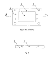
FIG.1 is a structural schematic diagram of theembodiment 1 of the jointed bipolar plate for fuel cell in accordance with the invention. -
FIG.2 is an A-A sectional view of theembodiment 2 of the jointed bipolar plate for fuel cell in accordance with the invention. -
FIG.3 is an A-A sectional view of theembodiment 3 of the jointed bipolar plate for fuel cell in accordance with the invention. -
FIG.4 is an A-A sectional view of theembodiment 4 of the jointed bipolar plate for fuel cell in accordance with the invention. -
FIG.5 is an A-A sectional view of theembodiment 5 of the jointed bipolar plate for fuel cell in accordance with the invention. - Shown as
FIG.1 , a bipolar plate for fuel cell comprises anelectrochemical reaction region 1 and anon-electrochemical reaction region 2 that are jointed with each other. - In the invention, the
electrochemical reaction region 1 of the bipolar plate 10 is an region where fuel supplied reacts with oxidant, this region is corresponding to a proton exchange membrane, and to the parts on the bipolar plate which come into direct contact with the proton exchange membrane, such as channel and gas diffusion layer, and generally, the proton exchange membrane is further provided with a catalyst coating. Thenon-electrochemical reaction region 2 is an region where no electrochemical reaction occurs. Thenon-electrochemical reaction region 2 is used for supporting theelectrochemical reaction region 1 and withstanding external acting forces. - The
electrochemical reaction regions 1 and the non-electrochemical reaction region 2 of the bipolar plate are divided in design, which could reduce design difficulty. For example, the material for the bipolar plate in theelectrochemical reaction region 1 may be materials that meet the demands of the bipolar plate for fuel cell, e.g. carbon plate, metal plate and the like. And the material for the bipolar plate in thenon-electrochemical reaction region 2 may be materials with certain strength and heat resistance, low cost and easy machining and formation. These two regions can be recovered respectively and then reused even if theelectrochemical reaction region 1 becomes ineffective. As a result, fuel cell stack becomes more environment-friendly. - Further, the
non-electrochemical reaction region 2 is made of a non-conductive material, such as ABS (styrene-butadiene-acrylonitrile-based ternary copolymer), PVC (polyvinyl chloride) and other insulating materials, and particularly, some materials with small density can be used for this region, for example, the material density of thenon-electrochemical reaction region 2 is 0.1 to 1.5g/cm3, those skilled in this art could flexibly select the material of this region as required, and the non-electrochemical reaction region can support theelectrochemical reaction region 1, withstand external acting forces and be insulating only if the material meets the demands on the performances of material for this region in the invention. In this way, the weight of fuel cell manufactured can be remarkably reduced to further lower energy consumption. In the prior bipolar plates for fuel cell, both the reaction region and the non-reaction region at the periphery thereof are made of the same or similar conductive material, causing that a part of current generated by reaction passes through the non-reaction region at the periphery of the reaction region to form eddy current, as a result, gradient deviation of current and loss of current could be caused, and this disadvantageous current distribution is possibly liable to result in the shortening of the service life of fuel cell stack and even the occurrence of current short circuit. According to this invention, theelectrochemical reaction region 1 and thenon-electrochemical reaction region 2 of the bipolar plate are separated in design and insulating materials are used for fabiration of thenon-electrochemical reaction region 2, so current could pass through theelectrochemical reaction region 2 uniformly to avoid the generation of eddy current and improve the service life of fuel cell, prevent the occurrence of current short circuit and enhance the application safety of fuel cell. - Wherein, electrochemical reaction region is at the center position of the bipolar plate. The non-electrochemical reaction region is located around the electrochemical reaction region.
- Wherein, the
non-electrochemical reaction region 2 is provided with areactant conveying passage 4 connected to channels of theelectrochemical reaction region 1. Theconveying passage 4 is used for conveying reactant of theelectrochemical reaction region 1. The specific communication way and structure between theconveying passage 4 and the channel of thenon-electrochemical reaction region 2 may be achieved by a number of techniques in prior art of bipolar plate designs, so detailed description regarding this part is herein omitted. - Wherein, the
non-electrochemical reaction region 2 is provided with mountingholes 3 for the assembly of fuel cell stack. Compared with the current integrally-designed bipolar plate for fuel cell, the bipolar plate for fuel cell provided by the invention is lower in cost since no reaction occurs in thenon-electrochemical reaction region 2 and the material of this region is convenient for forming and machining, so the total weight of the materials of fuel cell is reduced dramatically as well, the worry about damage to the bipolar plate during assembly is avoided, and the assembly requirement of fuel cell stack is lessened. - Wherein, based on manufacturing conditions, the part of the
electrochemical reaction region 1 for jointing with thenon-electrochemical reaction region 2 may be achieved in a number of approaches, such as jointing subsequent to adhesion, hot pressing and squeezing, etc. - Shown as
FIG.2 , this embodiment is the same as theembodiment 1 except the shape of the jointing part.FIG.2 is an A-A sectional view ofFIG.1 , inFIG.2 , the part of theelectrochemical reaction region 1 for jointing with thenon-electrochemical reaction region 2 is step-shaped, and the jointing part of thenon-electrochemical reaction region 2 is reverse step-shaped correspondingly. - Shown as
FIG.3 , this embodiment is the same as theembodiment 1 except the shape of the jointing part.FIG.3 is an A-A sectional view ofFIG.1 , inFIG.3 , the part of theelectrochemical reaction region 1 for jointing with thenon-electrochemical reaction region 2 is saw tooth-shaped, and the jointing part of thenon-electrochemical reaction region 2 is reverse saw tooth-shaped correspondingly. - Shown as
FIG.4 , this embodiment is the same as theembodiment 1 except the shape of the jointing part.FIG.4 is an A-A sectional view ofFIG.1 , inFIG.4 , the part of theelectrochemical reaction region 1 for jointing with thenon-electrochemical reaction region 2 is one or more than one protrusions, and the jointing part of thenon-electrochemical reaction region 2 is one or more than one corresponding grooves. - Or, the part of the
electrochemical reaction region 1 for jointing with thenon-electrochemical reaction region 2 is one or more than one grooves, and the jointing part of thenon-electrochemical reaction region 2 is one or more than one corresponding protrusions. - Shown as
Fig.5 , this embodiment is the same as theembodiment 1 except the shape of the jointing part.FIG.5 is an A-A sectional view ofFIG.1 , inFIG.5 , the jointing sidewalls of theelectrochemical reaction region 1 and thenon-electrochemical reaction region 2 are correspondingly provided with an annular groove respectively, and the annular groove is internally provided with anannular sealing strip 5. The sealing of the jointing parts at the sealing strips 5 is realized by the sealing strips 5. - During mounting, the annular sealing strips 5 can be embedded in the annular grooves of the
electrochemical reaction region 1 at first, and then theelectrochemical reaction region 1 is pressed into thenon-electrochemical reaction region 2. - The embodiments discussed above are merely for describing the technical concept and features of the invention, their objective is that those skilled in this art could understand the content of the invention and implement therefrom, limitation to the patent scope of the invention cannot be made only by these embodiments, for example, the connection between the
electrochemical reaction region 1 and thenon-electrochemical reaction region 2 is implemented in other jointing ways, and any other equivalent variations or modifications shall be contemplated as being within the patent scope of the invention only if the bipolar plate is designed in such a manner that the electrochemical reaction region and the non-electrochemical reaction region are separated from each other.
Claims (15)
- A bipolar plate for fuel cell, characterized in that: the bipolar plate comprises an electrochemical reaction region and a non-electrochemical reaction region that are jointed with each other.
- The bipolar plate for fuel cell according to claim 1, characterized in that: the electrochemical reaction region is located centrally, and the non-electrochemical reaction region is located around the electrochemical reaction region.
- The bipolar plate for fuel cell according to claim 2, characterized in that: the non-electrochemical reaction region is made of a non-conductive material.
- The bipolar plate for fuel cell according to claim 3, characterized in that: the material density of the non-electrochemical reaction region is 0.1 to 1.5g/cm3.
- The bipolar plate for fuel cell according to claim 3, characterized in that: the non-electrochemical reaction region is provided with a reactant conveying passage.
- The bipolar plate for fuel cell according to any of claims 1 to 5, characterized in that: the non-electrochemical reaction region is provided with mounting holes.
- The bipolar plate for fuel cell according to claim 6, characterized in that: a part of the electrochemical reaction region for jointing with the non-electrochemical reaction region is connected with a corresponding jointing part of the non-electrochemical reaction region in an adhesive manner.
- The bipolar plate for fuel cell according to claim 6, characterized in that: a part of the electrochemical reaction region for jointing with the non-electrochemical reaction region is connected with a corresponding jointing part of the non-electrochemical reaction region in a squeezing manner.
- The bipolar plate for fuel cell according to claim 6, characterized in that: a part of the electrochemical reaction region for jointing with the non-electrochemical reaction region is connected with a corresponding jointing part of the non-electrochemical reaction region in a hot-pressing manner.
- The bipolar plate for fuel cell according to any of claims 1 to 5 and claims 7 to 9, characterized in that: a part of the electrochemical reaction region for jointing with the non-electrochemical reaction region is step-shaped, and a jointing part of the non-electrochemical reaction region is reverse step-shaped correspondingly.
- The bipolar plate for fuel cell according to any of claims 1 to 5 and claims 7 to 9, characterized in that: a part of the electrochemical reaction region for jointing with the non-electrochemical reaction region is saw tooth-shaped, and a jointing part of the non-electrochemical reaction region is reverse saw tooth-shaped correspondingly.
- The bipolar plate for fuel cell according to any of claims 1 to 5 and claims 7 to 9, characterized in that: a part of the electrochemical reaction region for jointing with the non-electrochemical reaction region is one or more than one protrusions, and a jointing part of the non-electrochemical reaction region is one or more than one corresponding grooves.
- The bipolar plate for fuel cell according to any of claims 1 to 5 and claims 7 to 9, characterized in that: a part of the electrochemical reaction region for jointing with the non-electrochemical reaction region is one or more than one grooves, and a jointing part of the non-electrochemical reaction region is one or more than one corresponding protrusions.
- The bipolar plate for fuel cell according to any of claims 1 to 5 and claims 7 to 9, characterized in that: the jointing sidewalls of the electrochemical reaction region and the non-electrochemical reaction region are correspondingly provided with an annular groove respectively, and the annular groove is internally provided with an annular sealing strip.
- The bipolar plate for fuel cell according to any of claims 1 to 5 and claims 7 to 9, characterized in that: the electrochemical reaction region and the non-electrochemical reaction region have the same thickness.
Applications Claiming Priority (2)
| Application Number | Priority Date | Filing Date | Title |
|---|---|---|---|
| CN201010136286A CN101826621A (en) | 2010-03-30 | 2010-03-30 | Bipolar plate for fuel cells |
| PCT/CN2011/072272 WO2011120426A1 (en) | 2010-03-30 | 2011-03-29 | Bipolar plate for fuel cell |
Publications (3)
| Publication Number | Publication Date |
|---|---|
| EP2492997A1 true EP2492997A1 (en) | 2012-08-29 |
| EP2492997A4 EP2492997A4 (en) | 2012-11-28 |
| EP2492997B1 EP2492997B1 (en) | 2014-05-14 |
Family
ID=42690413
Family Applications (1)
| Application Number | Title | Priority Date | Filing Date |
|---|---|---|---|
| EP11762000.5A Active EP2492997B1 (en) | 2010-03-30 | 2011-03-29 | Bipolar plate for fuel cell |
Country Status (4)
| Country | Link |
|---|---|
| US (1) | US9231257B2 (en) |
| EP (1) | EP2492997B1 (en) |
| CN (1) | CN101826621A (en) |
| WO (1) | WO2011120426A1 (en) |
Cited By (1)
| Publication number | Priority date | Publication date | Assignee | Title |
|---|---|---|---|---|
| CN103985886A (en) * | 2013-02-07 | 2014-08-13 | 上海恒劲动力科技有限公司 | Fuel cell netted support bipolar plate and electric pile comprising fuel cell netted support bipolar plate |
Families Citing this family (8)
| Publication number | Priority date | Publication date | Assignee | Title |
|---|---|---|---|---|
| CN101826621A (en) * | 2010-03-30 | 2010-09-08 | 上海恒劲动力科技有限公司 | Bipolar plate for fuel cells |
| CN103436642A (en) * | 2013-01-07 | 2013-12-11 | 张琴中 | Needle plate |
| CN103474673B (en) * | 2013-09-24 | 2016-06-29 | 大连融科储能技术发展有限公司 | A kind of flow battery bipolar plates |
| CN105529478B (en) * | 2014-09-29 | 2018-07-06 | 上海恒劲动力科技有限公司 | A kind of pile of fuel battery double plates and its composition |
| CN108365250B (en) * | 2018-01-22 | 2024-03-08 | 国鸿氢能科技(嘉兴)股份有限公司 | Fixing device for fuel cell stack and fuel cell stack |
| CN110444785A (en) * | 2019-08-30 | 2019-11-12 | 湖南理工燃料电池有限公司 | Dual polar plates of proton exchange membrane fuel cell, battery and battery pile |
| CN114023990A (en) * | 2021-11-03 | 2022-02-08 | 无锡威孚高科技集团股份有限公司 | Fuel cell packaging plate and integrated double-sided fuel cell packaging piece |
| CN115832348B (en) * | 2022-12-02 | 2023-09-01 | 寰泰储能科技股份有限公司 | Composite bipolar plate for vanadium battery and preparation method thereof |
Citations (5)
| Publication number | Priority date | Publication date | Assignee | Title |
|---|---|---|---|---|
| EP1284512A2 (en) * | 2001-08-16 | 2003-02-19 | Asia Pacific Fuel Cell Technologies, Ltd. | Bipolar plate for a fuel cell |
| US20030194597A1 (en) * | 2002-04-14 | 2003-10-16 | Ganski Albin Von | Contact plate for an electrochemical cell, process and an injection mold for producing the contact plate and contact plate assembly |
| EP1416556A1 (en) * | 2002-10-16 | 2004-05-06 | Matsushita Electric Industrial Co., Ltd. | Separator plate for polymer electrolyte fuel cell and polymer electrolyte fuel cell using the same |
| US20070292736A1 (en) * | 2006-06-20 | 2007-12-20 | Steigerwalt Eve S | Fuel cell separator plate and method of forming same |
| CN201655892U (en) * | 2010-03-30 | 2010-11-24 | 上海恒劲动力科技有限公司 | Fuel battery splicing bipolar plate |
Family Cites Families (12)
| Publication number | Priority date | Publication date | Assignee | Title |
|---|---|---|---|---|
| US7736783B2 (en) * | 2002-12-04 | 2010-06-15 | Lynntech, Inc. | Very thin, light bipolar plates |
| DE10261482A1 (en) * | 2002-12-23 | 2004-07-01 | Basf Ag | Fuel cell module for polymer electrolyte membrane fuel cell stacks used e.g. in vehicles comprises a bipolar plate and a membrane-electrode unit |
| US20040191603A1 (en) * | 2003-03-25 | 2004-09-30 | Kaiser Joseph G. | Clad metallic bipolar plates and electricity-producing systems and fuel cells using the same |
| JP4959343B2 (en) * | 2004-01-22 | 2012-06-20 | ヘンケル コーポレイション | Polymerizable composition for bonding and sealing low surface energy substrates for fuel cells |
| CN100464450C (en) * | 2004-02-27 | 2009-02-25 | 上海神力科技有限公司 | Diversion polar plates of fuel cell in high mechanical strength |
| CN2694502Y (en) * | 2004-05-21 | 2005-04-20 | 天津大学 | Double plates for combined type proton exchange film battery |
| FR2875057B1 (en) * | 2004-09-09 | 2006-10-20 | Air Liquide | SEAL AND FUEL CELL PLATE, RESULTING CELLS, AND FUEL CELL COMPRISING A STACK OF SUCH CELLS |
| CN100444445C (en) * | 2005-02-01 | 2008-12-17 | 上海神力科技有限公司 | Flow-collection mother-board and end-plate composite structure for fuel cells |
| US7749631B2 (en) * | 2005-06-01 | 2010-07-06 | Gm Global Technology Operations, Inc. | Fuel cell separator plate coating |
| CN101826621A (en) * | 2010-03-30 | 2010-09-08 | 上海恒劲动力科技有限公司 | Bipolar plate for fuel cells |
| CN101807708B (en) * | 2010-03-30 | 2012-02-22 | 上海恒劲动力科技有限公司 | Fuel cell containing multiple independent cell subunit groups |
| CN201741756U (en) * | 2010-03-30 | 2011-02-09 | 上海恒劲动力科技有限公司 | Fuel cell comprising pluralities of independent battery sub-units |
-
2010
- 2010-03-30 CN CN201010136286A patent/CN101826621A/en active Pending
-
2011
- 2011-03-29 WO PCT/CN2011/072272 patent/WO2011120426A1/en active Application Filing
- 2011-03-29 US US13/638,616 patent/US9231257B2/en not_active Expired - Fee Related
- 2011-03-29 EP EP11762000.5A patent/EP2492997B1/en active Active
Patent Citations (5)
| Publication number | Priority date | Publication date | Assignee | Title |
|---|---|---|---|---|
| EP1284512A2 (en) * | 2001-08-16 | 2003-02-19 | Asia Pacific Fuel Cell Technologies, Ltd. | Bipolar plate for a fuel cell |
| US20030194597A1 (en) * | 2002-04-14 | 2003-10-16 | Ganski Albin Von | Contact plate for an electrochemical cell, process and an injection mold for producing the contact plate and contact plate assembly |
| EP1416556A1 (en) * | 2002-10-16 | 2004-05-06 | Matsushita Electric Industrial Co., Ltd. | Separator plate for polymer electrolyte fuel cell and polymer electrolyte fuel cell using the same |
| US20070292736A1 (en) * | 2006-06-20 | 2007-12-20 | Steigerwalt Eve S | Fuel cell separator plate and method of forming same |
| CN201655892U (en) * | 2010-03-30 | 2010-11-24 | 上海恒劲动力科技有限公司 | Fuel battery splicing bipolar plate |
Non-Patent Citations (1)
| Title |
|---|
| See also references of WO2011120426A1 * |
Cited By (1)
| Publication number | Priority date | Publication date | Assignee | Title |
|---|---|---|---|---|
| CN103985886A (en) * | 2013-02-07 | 2014-08-13 | 上海恒劲动力科技有限公司 | Fuel cell netted support bipolar plate and electric pile comprising fuel cell netted support bipolar plate |
Also Published As
| Publication number | Publication date |
|---|---|
| EP2492997B1 (en) | 2014-05-14 |
| EP2492997A4 (en) | 2012-11-28 |
| CN101826621A (en) | 2010-09-08 |
| WO2011120426A1 (en) | 2011-10-06 |
| US9231257B2 (en) | 2016-01-05 |
| US20130022896A1 (en) | 2013-01-24 |
Similar Documents
| Publication | Publication Date | Title |
|---|---|---|
| US9231257B2 (en) | Bipolar plate for fuel cell including non-electrochemical reaction region comprising a non-conductive material | |
| CN101937997B (en) | Metallic bipolar plate of proton exchange membrane fuel cell and single cell and electric stack formed by same | |
| JP5078689B2 (en) | Fuel cell stack | |
| CN112838232B (en) | Full-through-hole metal fiber sintered body fuel cell bipolar plate and fuel cell stack | |
| CN104157895A (en) | Light-weight electric pile of polymer electrolyte membrane fuel battery and manufacturing method of light-weight electric pile | |
| CN211088400U (en) | Composite structure of diffusion layer of separator flow channel and fuel cell using same | |
| CN209929408U (en) | Metal plate fuel cell single cell structure with long service life and reliability and electric pile | |
| CN218039302U (en) | Battery unit and electric pile with same | |
| CN210866380U (en) | Proton exchange membrane fuel cell monomer and proton exchange membrane fuel cell stack | |
| JP5235581B2 (en) | Fuel cell separator | |
| JP5255849B2 (en) | Fuel cell and separator / seal structure | |
| CN102110838A (en) | Proton exchange membrane fuel cell stack | |
| CN212625671U (en) | Monopolar plate, bipolar plate and fuel cell | |
| CN112928293B (en) | Battery cell and stack | |
| CN201655892U (en) | Fuel battery splicing bipolar plate | |
| US11489173B2 (en) | Fuel cell and fuel cell stack comprising same | |
| CN113571724A (en) | Graphite bipolar plate | |
| KR102025750B1 (en) | Fuel cell separator for and the fuel cell stack having the same | |
| KR100546016B1 (en) | Current collector for fuel cell, manufacturing method thereof and fuel cell having same | |
| JP4304955B2 (en) | Solid polymer electrolyte fuel cell | |
| JP2005243401A (en) | Separator and direct methanol type fuel cell using it | |
| JP4422505B2 (en) | Fuel cell | |
| JP2006210212A (en) | Polymer electrolyte fuel cell | |
| EP3576200A1 (en) | Fuel cell stack | |
| JP2001126743A (en) | Polymer electrolytic fuel cell |
Legal Events
| Date | Code | Title | Description |
|---|---|---|---|
| PUAI | Public reference made under article 153(3) epc to a published international application that has entered the european phase |
Free format text: ORIGINAL CODE: 0009012 |
|
| 17P | Request for examination filed |
Effective date: 20120330 |
|
| AK | Designated contracting states |
Kind code of ref document: A1 Designated state(s): AL AT BE BG CH CY CZ DE DK EE ES FI FR GB GR HR HU IE IS IT LI LT LU LV MC MK MT NL NO PL PT RO RS SE SI SK SM TR |
|
| A4 | Supplementary search report drawn up and despatched |
Effective date: 20121025 |
|
| RIC1 | Information provided on ipc code assigned before grant |
Ipc: H01M 8/24 20060101ALI20121019BHEP Ipc: H01M 8/02 20060101ALI20121019BHEP Ipc: H01M 4/86 20060101AFI20121019BHEP Ipc: H01M 8/10 20060101ALN20121019BHEP |
|
| DAX | Request for extension of the european patent (deleted) | ||
| GRAP | Despatch of communication of intention to grant a patent |
Free format text: ORIGINAL CODE: EPIDOSNIGR1 |
|
| RIC1 | Information provided on ipc code assigned before grant |
Ipc: H01M 8/02 20060101ALI20131001BHEP Ipc: H01M 4/86 20060101AFI20131001BHEP Ipc: H01M 8/24 20060101ALI20131001BHEP Ipc: H01M 8/10 20060101ALN20131001BHEP |
|
| INTG | Intention to grant announced |
Effective date: 20131025 |
|
| GRAS | Grant fee paid |
Free format text: ORIGINAL CODE: EPIDOSNIGR3 |
|
| GRAA | (expected) grant |
Free format text: ORIGINAL CODE: 0009210 |
|
| AK | Designated contracting states |
Kind code of ref document: B1 Designated state(s): AL AT BE BG CH CY CZ DE DK EE ES FI FR GB GR HR HU IE IS IT LI LT LU LV MC MK MT NL NO PL PT RO RS SE SI SK SM TR |
|
| REG | Reference to a national code |
Ref country code: GB Ref legal event code: FG4D |
|
| REG | Reference to a national code |
Ref country code: AT Ref legal event code: REF Ref document number: 668878 Country of ref document: AT Kind code of ref document: T Effective date: 20140615 |
|
| REG | Reference to a national code |
Ref country code: IE Ref legal event code: FG4D |
|
| REG | Reference to a national code |
Ref country code: DE Ref legal event code: R096 Ref document number: 602011007083 Country of ref document: DE Effective date: 20140626 |
|
| REG | Reference to a national code |
Ref country code: NL Ref legal event code: VDEP Effective date: 20140514 Ref country code: AT Ref legal event code: MK05 Ref document number: 668878 Country of ref document: AT Kind code of ref document: T Effective date: 20140514 |
|
| REG | Reference to a national code |
Ref country code: LT Ref legal event code: MG4D |
|
| PG25 | Lapsed in a contracting state [announced via postgrant information from national office to epo] |
Ref country code: FI Free format text: LAPSE BECAUSE OF FAILURE TO SUBMIT A TRANSLATION OF THE DESCRIPTION OR TO PAY THE FEE WITHIN THE PRESCRIBED TIME-LIMIT Effective date: 20140514 Ref country code: IS Free format text: LAPSE BECAUSE OF FAILURE TO SUBMIT A TRANSLATION OF THE DESCRIPTION OR TO PAY THE FEE WITHIN THE PRESCRIBED TIME-LIMIT Effective date: 20140914 Ref country code: NO Free format text: LAPSE BECAUSE OF FAILURE TO SUBMIT A TRANSLATION OF THE DESCRIPTION OR TO PAY THE FEE WITHIN THE PRESCRIBED TIME-LIMIT Effective date: 20140814 Ref country code: GR Free format text: LAPSE BECAUSE OF FAILURE TO SUBMIT A TRANSLATION OF THE DESCRIPTION OR TO PAY THE FEE WITHIN THE PRESCRIBED TIME-LIMIT Effective date: 20140815 Ref country code: CY Free format text: LAPSE BECAUSE OF FAILURE TO SUBMIT A TRANSLATION OF THE DESCRIPTION OR TO PAY THE FEE WITHIN THE PRESCRIBED TIME-LIMIT Effective date: 20140514 Ref country code: LT Free format text: LAPSE BECAUSE OF FAILURE TO SUBMIT A TRANSLATION OF THE DESCRIPTION OR TO PAY THE FEE WITHIN THE PRESCRIBED TIME-LIMIT Effective date: 20140514 |
|
| PG25 | Lapsed in a contracting state [announced via postgrant information from national office to epo] |
Ref country code: HR Free format text: LAPSE BECAUSE OF FAILURE TO SUBMIT A TRANSLATION OF THE DESCRIPTION OR TO PAY THE FEE WITHIN THE PRESCRIBED TIME-LIMIT Effective date: 20140514 Ref country code: AT Free format text: LAPSE BECAUSE OF FAILURE TO SUBMIT A TRANSLATION OF THE DESCRIPTION OR TO PAY THE FEE WITHIN THE PRESCRIBED TIME-LIMIT Effective date: 20140514 Ref country code: RS Free format text: LAPSE BECAUSE OF FAILURE TO SUBMIT A TRANSLATION OF THE DESCRIPTION OR TO PAY THE FEE WITHIN THE PRESCRIBED TIME-LIMIT Effective date: 20140514 Ref country code: LV Free format text: LAPSE BECAUSE OF FAILURE TO SUBMIT A TRANSLATION OF THE DESCRIPTION OR TO PAY THE FEE WITHIN THE PRESCRIBED TIME-LIMIT Effective date: 20140514 Ref country code: PL Free format text: LAPSE BECAUSE OF FAILURE TO SUBMIT A TRANSLATION OF THE DESCRIPTION OR TO PAY THE FEE WITHIN THE PRESCRIBED TIME-LIMIT Effective date: 20140514 Ref country code: ES Free format text: LAPSE BECAUSE OF FAILURE TO SUBMIT A TRANSLATION OF THE DESCRIPTION OR TO PAY THE FEE WITHIN THE PRESCRIBED TIME-LIMIT Effective date: 20140514 Ref country code: SE Free format text: LAPSE BECAUSE OF FAILURE TO SUBMIT A TRANSLATION OF THE DESCRIPTION OR TO PAY THE FEE WITHIN THE PRESCRIBED TIME-LIMIT Effective date: 20140514 |
|
| PG25 | Lapsed in a contracting state [announced via postgrant information from national office to epo] |
Ref country code: PT Free format text: LAPSE BECAUSE OF FAILURE TO SUBMIT A TRANSLATION OF THE DESCRIPTION OR TO PAY THE FEE WITHIN THE PRESCRIBED TIME-LIMIT Effective date: 20140915 |
|
| PG25 | Lapsed in a contracting state [announced via postgrant information from national office to epo] |
Ref country code: SK Free format text: LAPSE BECAUSE OF FAILURE TO SUBMIT A TRANSLATION OF THE DESCRIPTION OR TO PAY THE FEE WITHIN THE PRESCRIBED TIME-LIMIT Effective date: 20140514 Ref country code: EE Free format text: LAPSE BECAUSE OF FAILURE TO SUBMIT A TRANSLATION OF THE DESCRIPTION OR TO PAY THE FEE WITHIN THE PRESCRIBED TIME-LIMIT Effective date: 20140514 Ref country code: BE Free format text: LAPSE BECAUSE OF FAILURE TO SUBMIT A TRANSLATION OF THE DESCRIPTION OR TO PAY THE FEE WITHIN THE PRESCRIBED TIME-LIMIT Effective date: 20140514 Ref country code: DK Free format text: LAPSE BECAUSE OF FAILURE TO SUBMIT A TRANSLATION OF THE DESCRIPTION OR TO PAY THE FEE WITHIN THE PRESCRIBED TIME-LIMIT Effective date: 20140514 Ref country code: CZ Free format text: LAPSE BECAUSE OF FAILURE TO SUBMIT A TRANSLATION OF THE DESCRIPTION OR TO PAY THE FEE WITHIN THE PRESCRIBED TIME-LIMIT Effective date: 20140514 Ref country code: RO Free format text: LAPSE BECAUSE OF FAILURE TO SUBMIT A TRANSLATION OF THE DESCRIPTION OR TO PAY THE FEE WITHIN THE PRESCRIBED TIME-LIMIT Effective date: 20140514 |
|
| REG | Reference to a national code |
Ref country code: DE Ref legal event code: R097 Ref document number: 602011007083 Country of ref document: DE |
|
| PG25 | Lapsed in a contracting state [announced via postgrant information from national office to epo] |
Ref country code: NL Free format text: LAPSE BECAUSE OF FAILURE TO SUBMIT A TRANSLATION OF THE DESCRIPTION OR TO PAY THE FEE WITHIN THE PRESCRIBED TIME-LIMIT Effective date: 20140514 |
|
| PLBE | No opposition filed within time limit |
Free format text: ORIGINAL CODE: 0009261 |
|
| STAA | Information on the status of an ep patent application or granted ep patent |
Free format text: STATUS: NO OPPOSITION FILED WITHIN TIME LIMIT |
|
| 26N | No opposition filed |
Effective date: 20150217 |
|
| PG25 | Lapsed in a contracting state [announced via postgrant information from national office to epo] |
Ref country code: IT Free format text: LAPSE BECAUSE OF FAILURE TO SUBMIT A TRANSLATION OF THE DESCRIPTION OR TO PAY THE FEE WITHIN THE PRESCRIBED TIME-LIMIT Effective date: 20140514 |
|
| REG | Reference to a national code |
Ref country code: DE Ref legal event code: R097 Ref document number: 602011007083 Country of ref document: DE Effective date: 20150217 |
|
| PG25 | Lapsed in a contracting state [announced via postgrant information from national office to epo] |
Ref country code: SI Free format text: LAPSE BECAUSE OF FAILURE TO SUBMIT A TRANSLATION OF THE DESCRIPTION OR TO PAY THE FEE WITHIN THE PRESCRIBED TIME-LIMIT Effective date: 20140514 |
|
| PG25 | Lapsed in a contracting state [announced via postgrant information from national office to epo] |
Ref country code: MC Free format text: LAPSE BECAUSE OF FAILURE TO SUBMIT A TRANSLATION OF THE DESCRIPTION OR TO PAY THE FEE WITHIN THE PRESCRIBED TIME-LIMIT Effective date: 20140514 Ref country code: LU Free format text: LAPSE BECAUSE OF FAILURE TO SUBMIT A TRANSLATION OF THE DESCRIPTION OR TO PAY THE FEE WITHIN THE PRESCRIBED TIME-LIMIT Effective date: 20150329 |
|
| REG | Reference to a national code |
Ref country code: CH Ref legal event code: PL |
|
| REG | Reference to a national code |
Ref country code: IE Ref legal event code: MM4A |
|
| PG25 | Lapsed in a contracting state [announced via postgrant information from national office to epo] |
Ref country code: CH Free format text: LAPSE BECAUSE OF NON-PAYMENT OF DUE FEES Effective date: 20150331 Ref country code: LI Free format text: LAPSE BECAUSE OF NON-PAYMENT OF DUE FEES Effective date: 20150331 Ref country code: IE Free format text: LAPSE BECAUSE OF NON-PAYMENT OF DUE FEES Effective date: 20150329 |
|
| REG | Reference to a national code |
Ref country code: FR Ref legal event code: PLFP Year of fee payment: 6 |
|
| PG25 | Lapsed in a contracting state [announced via postgrant information from national office to epo] |
Ref country code: MT Free format text: LAPSE BECAUSE OF FAILURE TO SUBMIT A TRANSLATION OF THE DESCRIPTION OR TO PAY THE FEE WITHIN THE PRESCRIBED TIME-LIMIT Effective date: 20140514 |
|
| REG | Reference to a national code |
Ref country code: FR Ref legal event code: PLFP Year of fee payment: 7 |
|
| PG25 | Lapsed in a contracting state [announced via postgrant information from national office to epo] |
Ref country code: HU Free format text: LAPSE BECAUSE OF FAILURE TO SUBMIT A TRANSLATION OF THE DESCRIPTION OR TO PAY THE FEE WITHIN THE PRESCRIBED TIME-LIMIT; INVALID AB INITIO Effective date: 20110329 Ref country code: BG Free format text: LAPSE BECAUSE OF FAILURE TO SUBMIT A TRANSLATION OF THE DESCRIPTION OR TO PAY THE FEE WITHIN THE PRESCRIBED TIME-LIMIT Effective date: 20140514 Ref country code: SM Free format text: LAPSE BECAUSE OF FAILURE TO SUBMIT A TRANSLATION OF THE DESCRIPTION OR TO PAY THE FEE WITHIN THE PRESCRIBED TIME-LIMIT Effective date: 20140514 |
|
| PG25 | Lapsed in a contracting state [announced via postgrant information from national office to epo] |
Ref country code: TR Free format text: LAPSE BECAUSE OF FAILURE TO SUBMIT A TRANSLATION OF THE DESCRIPTION OR TO PAY THE FEE WITHIN THE PRESCRIBED TIME-LIMIT Effective date: 20140514 |
|
| REG | Reference to a national code |
Ref country code: FR Ref legal event code: PLFP Year of fee payment: 8 |
|
| PG25 | Lapsed in a contracting state [announced via postgrant information from national office to epo] |
Ref country code: MK Free format text: LAPSE BECAUSE OF FAILURE TO SUBMIT A TRANSLATION OF THE DESCRIPTION OR TO PAY THE FEE WITHIN THE PRESCRIBED TIME-LIMIT Effective date: 20140514 |
|
| PG25 | Lapsed in a contracting state [announced via postgrant information from national office to epo] |
Ref country code: AL Free format text: LAPSE BECAUSE OF FAILURE TO SUBMIT A TRANSLATION OF THE DESCRIPTION OR TO PAY THE FEE WITHIN THE PRESCRIBED TIME-LIMIT Effective date: 20140514 |
|
| PGFP | Annual fee paid to national office [announced via postgrant information from national office to epo] |
Ref country code: FR Payment date: 20230322 Year of fee payment: 13 |
|
| PGFP | Annual fee paid to national office [announced via postgrant information from national office to epo] |
Ref country code: GB Payment date: 20230321 Year of fee payment: 13 Ref country code: DE Payment date: 20230320 Year of fee payment: 13 |
|
| REG | Reference to a national code |
Ref country code: DE Ref legal event code: R082 Ref document number: 602011007083 Country of ref document: DE Representative=s name: SUN, YIMING, M.SC. DIPL. SC. POL. UNIV., DE |