EP2492940B1 - Switch Device - Google Patents
Switch Device Download PDFInfo
- Publication number
- EP2492940B1 EP2492940B1 EP12154717.8A EP12154717A EP2492940B1 EP 2492940 B1 EP2492940 B1 EP 2492940B1 EP 12154717 A EP12154717 A EP 12154717A EP 2492940 B1 EP2492940 B1 EP 2492940B1
- Authority
- EP
- European Patent Office
- Prior art keywords
- operating body
- driving body
- rocking
- operating
- case
- Prior art date
- Legal status (The legal status is an assumption and is not a legal conclusion. Google has not performed a legal analysis and makes no representation as to the accuracy of the status listed.)
- Active
Links
- 230000007935 neutral effect Effects 0.000 description 4
- 230000005856 abnormality Effects 0.000 description 3
- 239000011435 rock Substances 0.000 description 3
- 230000004075 alteration Effects 0.000 description 1
- 230000001419 dependent effect Effects 0.000 description 1
- 238000012986 modification Methods 0.000 description 1
- 230000004048 modification Effects 0.000 description 1
- 238000005096 rolling process Methods 0.000 description 1
Images
Classifications
-
- H—ELECTRICITY
- H01—ELECTRIC ELEMENTS
- H01H—ELECTRIC SWITCHES; RELAYS; SELECTORS; EMERGENCY PROTECTIVE DEVICES
- H01H23/00—Tumbler or rocker switches, i.e. switches characterised by being operated by rocking an operating member in the form of a rocker button
- H01H23/02—Details
- H01H23/12—Movable parts; Contacts mounted thereon
- H01H23/16—Driving mechanisms
- H01H23/20—Driving mechanisms having snap action
- H01H23/205—Driving mechanisms having snap action using a compression spring between tumbler and an articulated contact plate
-
- H—ELECTRICITY
- H01—ELECTRIC ELEMENTS
- H01H—ELECTRIC SWITCHES; RELAYS; SELECTORS; EMERGENCY PROTECTIVE DEVICES
- H01H23/00—Tumbler or rocker switches, i.e. switches characterised by being operated by rocking an operating member in the form of a rocker button
- H01H23/02—Details
- H01H23/12—Movable parts; Contacts mounted thereon
- H01H23/16—Driving mechanisms
- H01H23/162—Driving mechanisms incorporating links interconnecting tumbler and contact arm
-
- H—ELECTRICITY
- H01—ELECTRIC ELEMENTS
- H01H—ELECTRIC SWITCHES; RELAYS; SELECTORS; EMERGENCY PROTECTIVE DEVICES
- H01H23/00—Tumbler or rocker switches, i.e. switches characterised by being operated by rocking an operating member in the form of a rocker button
- H01H23/02—Details
- H01H23/12—Movable parts; Contacts mounted thereon
- H01H23/16—Driving mechanisms
- H01H23/168—Driving mechanisms using cams
-
- H—ELECTRICITY
- H01—ELECTRIC ELEMENTS
- H01H—ELECTRIC SWITCHES; RELAYS; SELECTORS; EMERGENCY PROTECTIVE DEVICES
- H01H23/00—Tumbler or rocker switches, i.e. switches characterised by being operated by rocking an operating member in the form of a rocker button
- H01H23/24—Tumbler or rocker switches, i.e. switches characterised by being operated by rocking an operating member in the form of a rocker button with two operating positions
-
- H—ELECTRICITY
- H01—ELECTRIC ELEMENTS
- H01H—ELECTRIC SWITCHES; RELAYS; SELECTORS; EMERGENCY PROTECTIVE DEVICES
- H01H2300/00—Orthogonal indexing scheme relating to electric switches, relays, selectors or emergency protective devices covered by H01H
- H01H2300/01—Application power window
Definitions
- the present invention relates to a switch device that performs a switching operation by a operating body is held in a case and made rockable, and particularly, to a switch device that performs a switching operation via a driving body in cooperation with the operating body.
- a switch device including a rockable operating body is used as a switch for operating a power window or a switch of a parking brake.
- a switch device that operates a power window a switch device is known in which a rockable operating body is provided in a case, a driving body that moves up and down with the rocking of the operating body is provided within the case, and a switch element is provided so as to face the driving body.
- US 7 026 565 B! discloses a rocker switch with an actuator subassembly that forms a self-contained unit removably inserted within the rocker switch to define the operating characteristics thereof and that includes an operating member operable between a plurality of positions, an extension and a spring-biased plunger, wherein a shaped member is pivotally coupled to the operating member and includes a plurality of shaped sections each corresponding to one of the positions of the operating member, each shaped section has a profile which is designed to provide the desired rocker switch operating characteristics, such as the type of action of the operating member and the operating force for the operating member.
- US 2008/0035457 A1 discloses a control knob supported on a switch base via a first pivotal shaft, wherein a movable contact holder holds a movable contact, is supported on the switch base via a second pivotal shaft substantially parallel with the first pivotal shaft, and is formed with first and second arms between which a sliding surface is formed.
- a control plunger sliding on the sliding surface is slidably fitted to the control knob.
- a return spring urges the control plunger in a direction to abut on the sliding surface.
- the control plunger is arranged such that, when the control knob tilts to the first and second operating positions, the tip end of the control plunger moves on the sliding surface to left and right sides with respect to a plane extending between axes of the first and second pivotal shafts, and such that the repulsive force of the return spring constantly urges the control knob toward the first operating position.
- US 6 040 543 A discloses a toggle switch with a main housing that contains an electrical contact assembly operated by a cam member which opens and closes the contacts through movement of a leaf spring, a modular assembly of a housing cover to which a manually operable pivotable handle is mounted and connected to a rotatable bushing supported shaft that operates a gear set attached to the cam member.
- the contacts provide an electrical connection to terminals that are insert molded into the housing.
- a switch element including two switching contacts that are simultaneously turned on and off is used as the switch device used for a parking brake.
- the switch element if the switch element is pressed and operated by a rocking operation of the operating body, the two switching contacts can be simultaneously switched. This allows a reliable operation even if there is an abnormality in any one of the switching contacts. If the outputs from the two switching contacts are detected within a predetermined time (for example, 100 ms), a control unit on the vehicle side determines this to be normal. Accordingly, with the rocking operation of the operating body, it is necessary to allow the two switching contacts in the switch element to be reliably switched within the predetermined time.
- the driving body does not operate at very high speed because the rocking speed of the operating body and the up-down movement speed of the driving body are almost the same. For this reason, when the switch element is pressed, there is a concern that a time difference may be caused in the switching of the two switching contacts, and an abnormality may be erroneously detected even though there is not abnormality in the switch element. Since such a problem does not occur if the driving body presses the switch element at high speed, a switch device in which the driving body can operate at higher speed than the operating body is desired.
- a switch device related to an embodiment of the present invention includes a operating body held in a case and made rockable; a driving body held within the case and made rockable by the operating body; and a switch element pressed by the driving body.
- the rockable operating body is held with respect to the case by a first rotating portion apart by a predetermined distance from a position where the operating body is operated.
- the rockable driving body is held with respect to the case by a second rotating portion apart by predetermined distance from a position where the driving body presses the switch element.
- a rocking portion that makes the operating body and the driving body rockable relative to each other between the first rotating portion and the second rotating portion is constituted by the operating body and the driving body.
- any one of the operating body and the driving body may be formed with a shaft portion, and the other of the operating body and the driving body may be formed with a holding portion that holds the shaft portion while allowing the shaft portion to rotate and slide.
- the holding portion may be formed in the shape of a substantially U-shaped slit or long hole.
- the distance between the second rotating portion of the driving body and a position where the driving body presses the switch element may be larger than the distance between the second rotating portion and the rocking portion.
- a rocking portion that makes the operating body and the driving body rockable relative to each other between the first rotating portion of the operating body and the second rotating portion of the driving body is constituted by the operating body and the driving body.
- any one of the operating body and the driving body is formed with a shaft portion, and the other of the operating body and the driving body is formed with a holding portion that holds the shaft portion while allowing the shaft portion to rotate and slide.
- the rocking portion can be constructed with a simple structure.
- the holding portion is formed in the shape of a substantially U-shaped slit or long hole. Therefore, the holding portion that allows the shaft portion to rotate and slide can be realized with a simple shape.
- the distance between the second rotating portion of the driving body and a position where the driving body presses the switch element is larger than the distance between the second rotating portion and the rocking portion.
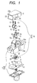
- FIG. 1 An exploded perspective view of a switch device in the present embodiment is shown in Fig. 1 .
- the switch device of the present embodiment is adapted such that a rockable operating body 2 is attached to a case 1 and made rockable including an upper case 10 and a lower case 11, and a board 12 on which two switch elements 4 are arranged is housed within the case 1, and one of the switch elements 4 is pressed and operated with the rocking operation of the operating body 2.
- An operating body holding portion 10a holding the operating body 2 is formed in the upper case 10 constituting the case 1 so as to protrude upward.
- Projection-like shaft portions 10b are formed on both sides of the operating body holding portion 10a, respectively.
- hole-shaped first rotating portions 20 are formed also in both sides of the operating body 2, respectively, and the operating body 2 is made rockable about the first rotating portions 20 with respect to the case 1 by causing the shaft portions 10b to be inserted through the first rotating portions 20.
- an operating portion 22 including a concave surface is formed in one of the surfaces that face each other adjacent to a pair of surfaces having the first rotating portions 20.
- the operating body 2 can be rocked in one direction (in the counterclockwise direction in Fig. 3 ).
- an upper end position in a curved surface that constitutes the operating portion 22 is supposed to be an operation position 22a to which a force for rocking is applied, the operating body 2 can be rocked in the other direction by pushing in the vicinity of the operation position 22a with a finger.
- the switch device is provided with a mechanism for giving a click feel with respect to the rocking of the operating body 2.
- a rolling cylindrical distal end member 15 is attached to a distal end portion of each sliding member 14.
- the cam members 5 are provided with cam surface portions 5b that are upwardly inclined, respectively, toward both side portions from a central portion. Each cam surface portion 5b is formed with a point that changes in the angle of inclination on the way. Additionally, the sliding member 14 is biased in a direction in which the sliding member is pressed against the cam surface portion 5b by the elastic member 13, and the cam surface portion 5b can smoothly slide by the distal end member 15.
- cam member 5 has a hole-shaped pivot portion 5a at a lower portion thereof.
- a rockable driving body 3 is attached to the pivot portions 5a. As the rockable driving body 3 is attached to the cam members 5 fixed to the upper case 10, the driving body 3 is made rockable with respect to the case 1.
- the driving body 3 has second rotating portions 30 inserted through the pivot portions 5a.
- the second rotating portions 30 are formed in the shape of projections that turn to the inside of the driving body 3, and is fitted to the pivot portions 5a from the external surface side of the pivot portions, and is made rotatable with respect to the case 1.
- one second rotating portion 30 is illustrated in Fig. 1
- the other second rotating portion is also similarly formed on the opposite surface that faces the one second rotating portion.
- the driving body 3 has projection-like shaft portions 31 above the second rotating portions 30.
- the shaft portions 31 are formed in the shape of projections that turn to the outside of the driving body 3.
- the operating body 2 has holding portions 21 formed substantially in the shape of the letter U below the first rotating portions 20.
- a rocking portion 16 that enables the driving body 3 to be rockable with respect to the operating body 2 is constructed by each shaft portion 31 of the driving body 3 through each holding portion 21. As such, the driving body 3 is rockable with respect to the case 1, and is also made rockable with respect to the operating body 2.
- pressing portions 32 are formed at the driving body 3 so as to extend respectively toward both side portions from a central portion where the second rotating portions 30 and the shaft portions 31 are formed.
- the pressing portions 32 are arranged to face the two switch elements 4 and 4 arranged on the board 12 so as to be able to press the switch elements, respectively.
- a pressing portion 32 presses a pressed portion 4a of one of the switch elements 4 on a lower surface thereof at the distal end.
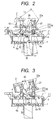
- FIG. 2 shows a state where the operating body 2 is at a neutral position where the operating body is rocked and operated.
- the driving body 3 is also in the neutral position, and both the pressing portions 32 are in a state where the pressing portions face the pressing portions 4a of the switch elements 4, respectively, in close proximity thereto.
- the first rotating portion 20 of the operating body 2, the second rotating portion 30 of the driving body 3, and the rocking portion 16 are located on a straight line, and the rocking portion 16 is arranged at a position between the first rotating portion 20 and the second rotating portion 30.
- the distance from the operation position 22a of the operating body 2 to the first rotating portion 20 is defined as L 1
- the distance from the first rotating portion 20 to the rocking portion 16 is defined as L 2
- the distance from the rocking portion 16 to the second rotating portion 30 of the driving body 3 is defined as L 3
- the distance from the second rotating portion 30 to the position where the pressed portion 4a of the pressing portion 32 is pressed is defined as L 4 .
- the ratio of the distance L 4 from the second rotating portion 30 to a position where the pressed portion 4a of the pressing portion 32 is pressed to the distance L 3 from the rocking portion 16 to the second rotating portion 30 be made as large as possible.
- L 1 cannot be made so small.
- the switch device there are also limitations to the dimensions in the height direction and the length direction. Thus, the position of the first rotating portion 20 of the operating body 2 and the pressing position of the switch element 4 cannot be moved much.
- the rocking portion 16 can be formed at as lower a position as possible within a range of dimensional limitations of the switch device.
- L 2 can be made as large as possible
- L 3 can be made as small as possible
- the ratio of L 2 to L 1 can made large
- the ratio of L 4 to L 3 can be made large
- the pressing speed of the switch element 4 by the pressing portion 32 to the operation speed at the operation position 22a of the operating body 2 can be set large.
- FIG. 3 A cross-sectional view of the switch device when the operating body 2 is rocked and operated is shown in Fig. 3 .
- This drawing shows a state where a rocking operation is performed in a direction in which the operation position 22a of the operating body 2 is pulled upward.
- the operating body 2 is rocked and operated, the operating body 2 is turned about the first rotating portions 20 with respect to the case 1, and with this turning, the holding portion 21 that constitutes the rocking portion 16 rocks the shaft portion 31. At this time, the shaft portion 31 also moves slightly in the longitudinal direction thereof with respect to the holding portion 21.
- the driving body 3 Since the driving body 3 is made rockable about the second rotating portions 30 with respect to the case 1, if the holding portion 21 rocks the shaft portion 31 in the rocking portion 16, the driving body tilts to the side opposite to the tilting direction of the operating body 2, and the pressing portions 32 presses the pressed portion 4a of the switch element 4.
- the driving body 3 that is rocked by the rocking operation of the operating body 2 to press the switch element 4 is provided, and the rocking portion 16 that makes the operating body 2 and the driving body 3 rockable relative to each other is formed between the first rotating portion 20 that becomes the center of rotation of the operating body 2 with respect to the case 1 and the second rotating portions 30 that becomes the center of rotation of the driving body 3 with respect to the case 1.
- the ratio of the pressing speed in the pressing portion 32 of the driving body 3 to the operation speed in the operation position 22a of the operating body 2 can be set using two ratios, that is, the ratio of L 1 and L 2 , and the ratio of L 3 and L 4 , and such a design that the pressing speed in the pressing portion 32 can be made as high as possible within limitations, such as the dimensions of the switch device, can be allowed.
- the ratio of L 2 to L 1 can be made large, the ratio of L 4 to L 3 can be made large, and the pressing speed in the pressing portion 32 can be set large compared to the operation speed at the operation position 22a of the operating body 2.
- the first rotating portion 20 provided in the operating body 2 has a hole shape, and the case 1 is formed with the shaft portion 10b that journals the first rotating portion.
- the operating body 2 may be provided with the shaft portion, and the case 1 may be formed with the hole portion.
- the driving body 3 may be provided with the hole portion, and the case 1 may be provided with the shaft portion.
- the driving body 3 may be provided with the holding portion, and the operating body 2 may be provided with the shaft portion.
- the holding portion 21 that constitutes the rocking portion 16 is formed as a substantially U-shaped slit.
- the holding portion 21 may be formed as arbitrary shapes as long as the holding portion can hold the shaft portion 31 while allowing it to rotate and slide, and can for example be formed in the shape of a long hole.
Description
- The present invention relates to a switch device that performs a switching operation by a operating body is held in a case and made rockable, and particularly, to a switch device that performs a switching operation via a driving body in cooperation with the operating body.
- In automobiles, a switch device including a rockable operating body is used as a switch for operating a power window or a switch of a parking brake. As a switch device that operates a power window, a switch device is known in which a rockable operating body is provided in a case, a driving body that moves up and down with the rocking of the operating body is provided within the case, and a switch element is provided so as to face the driving body.
- In this case, if the operating body is operated so as to be rocked, the driving body moves down to press the switch element, thereby performing a switching operation. If the operation state is released, the driving body and the operating body can return to their original state by the restoring force of the switch element. As such a switch device, for example, is disclosed in
JP 2007-265740 A -
US 7 026 565 B! discloses a rocker switch with an actuator subassembly that forms a self-contained unit removably inserted within the rocker switch to define the operating characteristics thereof and that includes an operating member operable between a plurality of positions, an extension and a spring-biased plunger, wherein a shaped member is pivotally coupled to the operating member and includes a plurality of shaped sections each corresponding to one of the positions of the operating member, each shaped section has a profile which is designed to provide the desired rocker switch operating characteristics, such as the type of action of the operating member and the operating force for the operating member. -
US 2008/0035457 A1 discloses a control knob supported on a switch base via a first pivotal shaft, wherein a movable contact holder holds a movable contact, is supported on the switch base via a second pivotal shaft substantially parallel with the first pivotal shaft, and is formed with first and second arms between which a sliding surface is formed. A control plunger sliding on the sliding surface is slidably fitted to the control knob. A return spring urges the control plunger in a direction to abut on the sliding surface. The control plunger is arranged such that, when the control knob tilts to the first and second operating positions, the tip end of the control plunger moves on the sliding surface to left and right sides with respect to a plane extending between axes of the first and second pivotal shafts, and such that the repulsive force of the return spring constantly urges the control knob toward the first operating position. -
US 6 040 543 A discloses a toggle switch with a main housing that contains an electrical contact assembly operated by a cam member which opens and closes the contacts through movement of a leaf spring, a modular assembly of a housing cover to which a manually operable pivotable handle is mounted and connected to a rotatable bushing supported shaft that operates a gear set attached to the cam member. The contacts provide an electrical connection to terminals that are insert molded into the housing. - A switch element including two switching contacts that are simultaneously turned on and off is used as the switch device used for a parking brake. In this case, if the switch element is pressed and operated by a rocking operation of the operating body, the two switching contacts can be simultaneously switched. This allows a reliable operation even if there is an abnormality in any one of the switching contacts. If the outputs from the two switching contacts are detected within a predetermined time (for example, 100 ms), a control unit on the vehicle side determines this to be normal. Accordingly, with the rocking operation of the operating body, it is necessary to allow the two switching contacts in the switch element to be reliably switched within the predetermined time.
- In the related-art switch device used for a power window, the driving body does not operate at very high speed because the rocking speed of the operating body and the up-down movement speed of the driving body are almost the same. For this reason, when the switch element is pressed, there is a concern that a time difference may be caused in the switching of the two switching contacts, and an abnormality may be erroneously detected even though there is not abnormality in the switch element. Since such a problem does not occur if the driving body presses the switch element at high speed, a switch device in which the driving body can operate at higher speed than the operating body is desired.
- It is one object of the present invention to provide a switch device that can set the operating speed of a driving body at higher speed than the operating speed of the operating body.
- The object is solved by a switch device with the features of
independent claim 1. Further embodiments are defined in the dependent claims. - Accordingly, a switch device related to an embodiment of the present invention includes a operating body held in a case and made rockable; a driving body held within the case and made rockable by the operating body; and a switch element pressed by the driving body. The rockable operating body is held with respect to the case by a first rotating portion apart by a predetermined distance from a position where the operating body is operated. The rockable driving body is held with respect to the case by a second rotating portion apart by predetermined distance from a position where the driving body presses the switch element. A rocking portion that makes the operating body and the driving body rockable relative to each other between the first rotating portion and the second rotating portion is constituted by the operating body and the driving body.
- Additionally, in the switch device related to the embodiment of the present invention, as the rocking portion, any one of the operating body and the driving body may be formed with a shaft portion, and the other of the operating body and the driving body may be formed with a holding portion that holds the shaft portion while allowing the shaft portion to rotate and slide.
- Moreover, in the switch device related to the embodiment of the present invention, the holding portion may be formed in the shape of a substantially U-shaped slit or long hole.
- Furthermore, in the switch device related to the embodiment of the present invention, the distance between the second rotating portion of the driving body and a position where the driving body presses the switch element may be larger than the distance between the second rotating portion and the rocking portion.
- According to the switch device related to the embodiment of the present invention, a rocking portion that makes the operating body and the driving body rockable relative to each other between the first rotating portion of the operating body and the second rotating portion of the driving body is constituted by the operating body and the driving body. Thereby, since the ratio of the operation speed at the operation position of the operating body and the pressing speed at the pressing position of the driving body can be set by the ratio of the distance from the operation position of the operating body to the first rotating portion and the distance from the first rotating portion to the rocking portion and the ratio of the distance from the rocking portion to the second rotating portion and the distance from the second rotating portion to the pressing position by the pressing portion. Thus, such a design that the pressing speed of the switch element by the driving body can be made as high as possible within limitations, such as the dimensions of the switch device, can be allowed.
- Additionally, according to the switch device related to the present invention, as the rocking portion, any one of the operating body and the driving body is formed with a shaft portion, and the other of the operating body and the driving body is formed with a holding portion that holds the shaft portion while allowing the shaft portion to rotate and slide. Thereby, the rocking portion can be constructed with a simple structure.
- Moreover, according to the switch device related to the embodiment of the present invention, the holding portion is formed in the shape of a substantially U-shaped slit or long hole. Thereby, the holding portion that allows the shaft portion to rotate and slide can be realized with a simple shape.
- Furthermore, according to the switch device related to the embodiment of the present invention, the distance between the second rotating portion of the driving body and a position where the driving body presses the switch element is larger than the distance between the second rotating portion and the rocking portion. Thereby, the pressing speed of the switch can be made larger than the rocking speed in the rocking portion, and the reliable pressing operation of the switch element can be performed.
-
-
Fig. 1 is an exploded perspective view of a switch device in the present embodiment; -
Fig. 2 is a cross-sectional view of the switch device; and -
Fig. 3 is a cross-sectional view of the switch device when the operating body is rocked and operated. - An embodiment of the present invention will be described in detail with reference to the drawings. An exploded perspective view of a switch device in the present embodiment is shown in
Fig. 1 . As shown in this drawing, the switch device of the present embodiment is adapted such that arockable operating body 2 is attached to acase 1 and made rockable including anupper case 10 and alower case 11, and aboard 12 on which twoswitch elements 4 are arranged is housed within thecase 1, and one of theswitch elements 4 is pressed and operated with the rocking operation of theoperating body 2. - An operating
body holding portion 10a holding theoperating body 2 is formed in theupper case 10 constituting thecase 1 so as to protrude upward. Projection-like shaft portions 10b are formed on both sides of the operatingbody holding portion 10a, respectively. Corresponding to this, hole-shaped first rotatingportions 20 are formed also in both sides of theoperating body 2, respectively, and theoperating body 2 is made rockable about the first rotatingportions 20 with respect to thecase 1 by causing theshaft portions 10b to be inserted through the first rotatingportions 20. - In the
operating body 2, anoperating portion 22 including a concave surface is formed in one of the surfaces that face each other adjacent to a pair of surfaces having the first rotatingportions 20. As an operator hooks his/her finger on theoperating portion 22 to pull the operating portion upward, theoperating body 2 can be rocked in one direction (in the counterclockwise direction inFig. 3 ). In the present embodiment, if an upper end position in a curved surface that constitutes theoperating portion 22 is supposed to be anoperation position 22a to which a force for rocking is applied, theoperating body 2 can be rocked in the other direction by pushing in the vicinity of theoperation position 22a with a finger. - The switch device is provided with a mechanism for giving a click feel with respect to the rocking of the
operating body 2.Cam members 5 fixed to the inner surface of theupper case 10 and slidingmembers 14 attached to theoperating body 2 viaelastic members 13, respectively, constitute the mechanism for giving a click feel. A rolling cylindricaldistal end member 15 is attached to a distal end portion of each slidingmember 14. - The
cam members 5 are provided withcam surface portions 5b that are upwardly inclined, respectively, toward both side portions from a central portion. Eachcam surface portion 5b is formed with a point that changes in the angle of inclination on the way. Additionally, the slidingmember 14 is biased in a direction in which the sliding member is pressed against thecam surface portion 5b by theelastic member 13, and thecam surface portion 5b can smoothly slide by thedistal end member 15. - For this reason, if the operating
body 2 is rocked, a biasing force to the slidingmember 14 becomes a resistance force to a rocking operation, so that a moderate feeling of operation can be given. Additionally, a click feel can be given when the slidingmember 14 passes through the point where the angle of inclination of thecam surface portion 5b changes. - Additionally, the
cam member 5 has a hole-shapedpivot portion 5a at a lower portion thereof. Arockable driving body 3 is attached to thepivot portions 5a. As therockable driving body 3 is attached to thecam members 5 fixed to theupper case 10, the drivingbody 3 is made rockable with respect to thecase 1. - The driving
body 3 has second rotatingportions 30 inserted through thepivot portions 5a. The secondrotating portions 30 are formed in the shape of projections that turn to the inside of the drivingbody 3, and is fitted to thepivot portions 5a from the external surface side of the pivot portions, and is made rotatable with respect to thecase 1. In addition, although one second rotatingportion 30 is illustrated inFig. 1 , the other second rotating portion is also similarly formed on the opposite surface that faces the one second rotating portion. - Additionally, the driving
body 3 has projection-like shaft portions 31 above the secondrotating portions 30. Theshaft portions 31 are formed in the shape of projections that turn to the outside of the drivingbody 3. The operatingbody 2 has holdingportions 21 formed substantially in the shape of the letter U below the firstrotating portions 20. A rockingportion 16 that enables the drivingbody 3 to be rockable with respect to theoperating body 2 is constructed by eachshaft portion 31 of the drivingbody 3 through each holdingportion 21. As such, the drivingbody 3 is rockable with respect to thecase 1, and is also made rockable with respect to theoperating body 2. - Moreover, pressing
portions 32 are formed at the drivingbody 3 so as to extend respectively toward both side portions from a central portion where the secondrotating portions 30 and theshaft portions 31 are formed. Thepressing portions 32 are arranged to face the twoswitch elements board 12 so as to be able to press the switch elements, respectively. As the drivingbody 3 rocks with the rocking operation of the operatingbody 2, apressing portion 32 presses a pressedportion 4a of one of theswitch elements 4 on a lower surface thereof at the distal end. - A cross-sectional view of a switch device is shown in
Fig. 2. Fig. 2 shows a state where the operatingbody 2 is at a neutral position where the operating body is rocked and operated. When the operatingbody 2 is in the neutral position, the drivingbody 3 is also in the neutral position, and both thepressing portions 32 are in a state where the pressing portions face thepressing portions 4a of theswitch elements 4, respectively, in close proximity thereto. - When the operating
body 2 is at the neutral position, the first rotatingportion 20 of the operatingbody 2, the second rotatingportion 30 of the drivingbody 3, and the rockingportion 16 are located on a straight line, and the rockingportion 16 is arranged at a position between the first rotatingportion 20 and the second rotatingportion 30. - In
Fig. 2 , the distance from theoperation position 22a of the operatingbody 2 to the first rotatingportion 20 is defined as L1, the distance from the first rotatingportion 20 to the rockingportion 16 is defined as L2, the distance from the rockingportion 16 to the second rotatingportion 30 of the drivingbody 3 is defined as L3, and the distance from the second rotatingportion 30 to the position where the pressedportion 4a of thepressing portion 32 is pressed is defined as L4. These respective distances are determined in advance depending on the shape of the operatingbody 2 and the drivingbody 3. - In order to press the
switch element 4 at as high a speed as possible in thepressing portion 32 of the drivingbody 3 with the operation of the operatingbody 2, it is necessary to make the rocking speed in the rockingportion 16 as high as possible, and make the rocking speed in thepressing portion 32 as high as possible. In order to make the rocking speed in the rockingportion 16 as high as possible, it is desirable that the ratio of the distance L2 from the first rotatingportion 20 to the rockingportion 16 to the distance L1 from theoperation position 22a to the first rotatingportion 20 be made as large as possible. Additionally, in order to make the rocking speed in thepressing portion 32 as high as possible, it is desirable that the ratio of the distance L4 from the second rotatingportion 30 to a position where the pressedportion 4a of thepressing portion 32 is pressed to the distance L3 from the rockingportion 16 to the second rotatingportion 30 be made as large as possible. - However, since the operating
body 2 is required to have a certain degree of size for the rocking operation, and to secure a certain degree of radius of rotation from theoperation position 22a, L1 cannot be made so small. Additionally, in the switch device, there are also limitations to the dimensions in the height direction and the length direction. Thus, the position of the first rotatingportion 20 of the operatingbody 2 and the pressing position of theswitch element 4 cannot be moved much. - On the other hand, the rocking
portion 16 can be formed at as lower a position as possible within a range of dimensional limitations of the switch device. Thereby, L2 can be made as large as possible, L3 can be made as small as possible, and the ratio of L2 to L1 can made large, the ratio of L4 to L3 can be made large, and the pressing speed of theswitch element 4 by thepressing portion 32 to the operation speed at theoperation position 22a of the operatingbody 2 can be set large. - A cross-sectional view of the switch device when the operating
body 2 is rocked and operated is shown inFig. 3 . This drawing shows a state where a rocking operation is performed in a direction in which theoperation position 22a of the operatingbody 2 is pulled upward. When the operatingbody 2 is rocked and operated, the operatingbody 2 is turned about the firstrotating portions 20 with respect to thecase 1, and with this turning, the holdingportion 21 that constitutes the rockingportion 16 rocks theshaft portion 31. At this time, theshaft portion 31 also moves slightly in the longitudinal direction thereof with respect to the holdingportion 21. - Since the driving
body 3 is made rockable about the secondrotating portions 30 with respect to thecase 1, if the holdingportion 21 rocks theshaft portion 31 in the rockingportion 16, the driving body tilts to the side opposite to the tilting direction of the operatingbody 2, and thepressing portions 32 presses the pressedportion 4a of theswitch element 4. - When the operating
body 2 is rocked and operated in a direction opposite to that ofFig. 3 , that is, in a direction in which theoperation position 22a is pushed in, the drivingbody 3 tilts in the direction opposite to that ofFig. 3 , and the pressedportion 4a of theopposite switch element 4 is pressed by thepressing portion 32. - As such, the driving
body 3 that is rocked by the rocking operation of the operatingbody 2 to press theswitch element 4 is provided, and the rockingportion 16 that makes the operatingbody 2 and the drivingbody 3 rockable relative to each other is formed between the first rotatingportion 20 that becomes the center of rotation of the operatingbody 2 with respect to thecase 1 and the secondrotating portions 30 that becomes the center of rotation of the drivingbody 3 with respect to thecase 1. Thereby, the ratio of the pressing speed in thepressing portion 32 of the drivingbody 3 to the operation speed in theoperation position 22a of the operatingbody 2 can be set using two ratios, that is, the ratio of L1 and L2, and the ratio of L3 and L4, and such a design that the pressing speed in thepressing portion 32 can be made as high as possible within limitations, such as the dimensions of the switch device, can be allowed. - Particularly by arranging the position of the rocking
portion 16 at as lower a position as possible, the ratio of L2 to L1 can be made large, the ratio of L4 to L3 can be made large, and the pressing speed in thepressing portion 32 can be set large compared to the operation speed at theoperation position 22a of the operatingbody 2. Thereby, when two contacts are placed side by side inside theswitch element 4, the difference in the time taken when both contacts operate at the time of a pressing operation can be made small, and a reliable switching operation can be ensured. - Although a plurality of rotating and rocking portions is provided in the present embodiment, in these portions, the relationship between a protruding portion that comprise a rotating shaft and a hole portion that holds the protruding portion may be reversed. In the present embodiment, the first rotating
portion 20 provided in theoperating body 2 has a hole shape, and thecase 1 is formed with theshaft portion 10b that journals the first rotating portion. However, the operatingbody 2 may be provided with the shaft portion, and thecase 1 may be formed with the hole portion. Similarly, also as for the secondrotating portions 30, the drivingbody 3 may be provided with the hole portion, and thecase 1 may be provided with the shaft portion. - Similarly, also as for the rocking
portion 16, the drivingbody 3 may be provided with the holding portion, and theoperating body 2 may be provided with the shaft portion. Additionally, in the present embodiment, the holdingportion 21 that constitutes the rockingportion 16 is formed as a substantially U-shaped slit. However, the holdingportion 21 may be formed as arbitrary shapes as long as the holding portion can hold theshaft portion 31 while allowing it to rotate and slide, and can for example be formed in the shape of a long hole. - Although the embodiment of the present invention has been described hitherto, the present invention is not limited to the above embodiment in the application thereof, and it should be understood by those skilled in the art that various modifications, combinations, sub-combinations and alterations may occur depending on design requirements and other factors insofar as they are within the scope of the appended claims.
Claims (2)
- A switch device comprising:a operating body (2) held in a case (1) and made rockable;a driving body (3) held within the case (1) and made rockable by the operating body (2); anda switch element (4) configured to be pressable by the driving body (3),wherein the rocking operating body (2) is held with respect to the case (1) by a first rotating portion (20) as a center of rotation of the operating body (2) with respect to the case (1), said first rotating portion (20) having a first predetermined distance (L1) from a position where the operating body (2) is to be operated,wherein the driving body (3) is rockably held with respect to the case (1) by a second rotating portion (30) as a center of rotation of the driving body (3)with respect to the case (1), said second rotating portion (30) having a second predetermined distance (L4) from a position where the driving body is arranged to press the switch element (4),wherein a rocking portion (16), which makes the operating body (2) and the driving body (3) rockable relative to each other between the first rotating portion (20) and the second rotating portion (30), is constituted by the operating body (2) and the driving body (3), andwherein as the rocking portion (16), any one of the operating body (2) and the driving body (3) is formed with a shaft portion (31), and the other of the operating body (2) and the driving body (3) is formed with a holding portion (21) that holds the shaft portion (31) allowing the shaft portion to rotate and slide, and wherein the second predetermined distance (L4) between the second rotating portion (30) of the driving body (3) and a position where the driving body presses the switch element (4) is larger than a third predetermined distance (L3) between the second rotating portion (30) and the rocking portion (16).
- The switch device according to Claim 1,
wherein the holding portion (21) is formed in the shape of a substantially U-shaped slit or long hole.
Applications Claiming Priority (1)
| Application Number | Priority Date | Filing Date | Title |
|---|---|---|---|
| JP2011039727A JP5600858B2 (en) | 2011-02-25 | 2011-02-25 | Switch device |
Publications (2)
| Publication Number | Publication Date |
|---|---|
| EP2492940A1 EP2492940A1 (en) | 2012-08-29 |
| EP2492940B1 true EP2492940B1 (en) | 2016-07-20 |
Family
ID=45655523
Family Applications (1)
| Application Number | Title | Priority Date | Filing Date |
|---|---|---|---|
| EP12154717.8A Active EP2492940B1 (en) | 2011-02-25 | 2012-02-09 | Switch Device |
Country Status (3)
| Country | Link |
|---|---|
| US (1) | US8704118B2 (en) |
| EP (1) | EP2492940B1 (en) |
| JP (1) | JP5600858B2 (en) |
Cited By (1)
| Publication number | Priority date | Publication date | Assignee | Title |
|---|---|---|---|---|
| RU2810307C2 (en) * | 2019-04-26 | 2023-12-26 | Шнейдер Электрик Эндюстри Сас | Electrical installation device |
Families Citing this family (8)
| Publication number | Priority date | Publication date | Assignee | Title |
|---|---|---|---|---|
| JP6125820B2 (en) * | 2012-12-17 | 2017-05-10 | 株式会社ヴァレオジャパン | switch |
| DE102013014571A1 (en) * | 2013-09-02 | 2015-03-05 | GM Global Technology Operations LLC (n. d. Ges. d. Staates Delaware) | Handbrake device for a vehicle |
| DE102016014678A1 (en) | 2015-12-14 | 2017-06-14 | Marquardt Gmbh | Electric switch |
| JP6438448B2 (en) * | 2016-11-16 | 2018-12-12 | 株式会社東海理化電機製作所 | Switch device |
| JP2018129193A (en) * | 2017-02-08 | 2018-08-16 | 株式会社デンソー | Switch device |
| CN108447719A (en) * | 2018-03-20 | 2018-08-24 | 中山市红典照明有限公司 | Electric switch |
| DE102019110845A1 (en) * | 2019-04-26 | 2020-10-29 | Schneider Electric Industries Sas | Electrical installation device |
| US10879022B1 (en) | 2019-08-15 | 2020-12-29 | Denso International America, Inc. | Toggle switch |
Family Cites Families (11)
| Publication number | Priority date | Publication date | Assignee | Title |
|---|---|---|---|---|
| GB1105822A (en) | 1965-07-01 | 1968-03-13 | A F Bulgin & Company Ltd | Improvements relating to electric switches |
| US3681556A (en) * | 1971-10-26 | 1972-08-01 | Mc Gill Mfg Co | Snap-on rocker cap for electric switch |
| US4121068A (en) * | 1977-02-28 | 1978-10-17 | Trw Inc. | Polarity reversing electrical switch |
| JPS5726510Y2 (en) * | 1978-02-28 | 1982-06-09 | ||
| US4440994A (en) * | 1982-08-20 | 1984-04-03 | Eaton Corporation | Pivoted actuator off lock switch with operator key nonremovable in ON position |
| JP2525658Y2 (en) * | 1991-09-18 | 1997-02-12 | アルプス電気株式会社 | Seesaw switch |
| US6040543A (en) * | 1999-08-13 | 2000-03-21 | Egs Electrical Group Llc | Explosion proof toggle switch |
| US7026565B1 (en) * | 2004-12-27 | 2006-04-11 | Eaton Corporation | Self-contained actuator subassembly for a rocker switch and rocker switch employing the same |
| JP4528697B2 (en) * | 2005-09-05 | 2010-08-18 | アルプス電気株式会社 | Switch device |
| JP4653001B2 (en) | 2006-03-28 | 2011-03-16 | アルプス電気株式会社 | Switch device |
| JP4717747B2 (en) * | 2006-08-10 | 2011-07-06 | 東洋電装株式会社 | Automatic reset switch |
-
2011
- 2011-02-25 JP JP2011039727A patent/JP5600858B2/en active Active
-
2012
- 2012-02-09 EP EP12154717.8A patent/EP2492940B1/en active Active
- 2012-02-24 US US13/404,767 patent/US8704118B2/en active Active
Cited By (1)
| Publication number | Priority date | Publication date | Assignee | Title |
|---|---|---|---|---|
| RU2810307C2 (en) * | 2019-04-26 | 2023-12-26 | Шнейдер Электрик Эндюстри Сас | Electrical installation device |
Also Published As
| Publication number | Publication date |
|---|---|
| JP2012178247A (en) | 2012-09-13 |
| US8704118B2 (en) | 2014-04-22 |
| EP2492940A1 (en) | 2012-08-29 |
| US20120217144A1 (en) | 2012-08-30 |
| JP5600858B2 (en) | 2014-10-08 |
Similar Documents
| Publication | Publication Date | Title |
|---|---|---|
| EP2492940B1 (en) | Switch Device | |
| US4918264A (en) | Actuating mechanism and multiposition rubber or membrane switch device | |
| EP2638552B1 (en) | Switch with pivoting actuator | |
| JP5813725B2 (en) | Switch device | |
| JP6410358B2 (en) | Rotating switch device | |
| JP5893753B2 (en) | Reset device for automobile steering column switch system and automobile | |
| EP1524579A2 (en) | Joystick switching device | |
| JP5555015B2 (en) | In-vehicle input device | |
| US5089677A (en) | Switching dial and finger rest | |
| US9343249B2 (en) | Pressure and rotationally actuated control element for a motor vehicle | |
| EP1300859A2 (en) | Switch operating mechanism | |
| JP4390686B2 (en) | Switch device | |
| EP2755218B1 (en) | Combined operation type switch device | |
| JP4620636B2 (en) | Rotation operation type output device | |
| JP4271565B2 (en) | Control device for automobiles, especially for controlling in-vehicle computers | |
| EP3214632B1 (en) | Multidirectional input device | |
| JP5006293B2 (en) | Slide operation mechanism and slide operation type switch device provided with the mechanism | |
| EP2631108A1 (en) | Control device for seat adjustment | |
| JP7196353B1 (en) | Multidirectional input device | |
| CN209859033U (en) | Operating device | |
| EP3465715B1 (en) | Switch | |
| KR970003732Y1 (en) | Rotary switch | |
| JP7038325B2 (en) | Switch device, mobile | |
| JP4579857B2 (en) | Rotation operation type output device | |
| EP1457404B1 (en) | Steering wheel switch |
Legal Events
| Date | Code | Title | Description |
|---|---|---|---|
| PUAI | Public reference made under article 153(3) epc to a published international application that has entered the european phase |
Free format text: ORIGINAL CODE: 0009012 |
|
| AK | Designated contracting states |
Kind code of ref document: A1 Designated state(s): AL AT BE BG CH CY CZ DE DK EE ES FI FR GB GR HR HU IE IS IT LI LT LU LV MC MK MT NL NO PL PT RO RS SE SI SK SM TR |
|
| AX | Request for extension of the european patent |
Extension state: BA ME |
|
| 17P | Request for examination filed |
Effective date: 20121214 |
|
| GRAP | Despatch of communication of intention to grant a patent |
Free format text: ORIGINAL CODE: EPIDOSNIGR1 |
|
| RIC1 | Information provided on ipc code assigned before grant |
Ipc: H01H 23/16 20060101AFI20160219BHEP Ipc: H01H 23/20 20060101ALI20160219BHEP Ipc: H01H 23/24 20060101ALN20160219BHEP |
|
| INTG | Intention to grant announced |
Effective date: 20160307 |
|
| RIN1 | Information on inventor provided before grant (corrected) |
Inventor name: KONNO, SATORU |
|
| GRAS | Grant fee paid |
Free format text: ORIGINAL CODE: EPIDOSNIGR3 |
|
| GRAA | (expected) grant |
Free format text: ORIGINAL CODE: 0009210 |
|
| AK | Designated contracting states |
Kind code of ref document: B1 Designated state(s): AL AT BE BG CH CY CZ DE DK EE ES FI FR GB GR HR HU IE IS IT LI LT LU LV MC MK MT NL NO PL PT RO RS SE SI SK SM TR |
|
| REG | Reference to a national code |
Ref country code: GB Ref legal event code: FG4D |
|
| REG | Reference to a national code |
Ref country code: CH Ref legal event code: EP |
|
| REG | Reference to a national code |
Ref country code: IE Ref legal event code: FG4D |
|
| REG | Reference to a national code |
Ref country code: AT Ref legal event code: REF Ref document number: 814670 Country of ref document: AT Kind code of ref document: T Effective date: 20160815 |
|
| REG | Reference to a national code |
Ref country code: DE Ref legal event code: R096 Ref document number: 602012020606 Country of ref document: DE |
|
| REG | Reference to a national code |
Ref country code: LT Ref legal event code: MG4D |
|
| REG | Reference to a national code |
Ref country code: NL Ref legal event code: MP Effective date: 20160720 |
|
| REG | Reference to a national code |
Ref country code: AT Ref legal event code: MK05 Ref document number: 814670 Country of ref document: AT Kind code of ref document: T Effective date: 20160720 |
|
| PG25 | Lapsed in a contracting state [announced via postgrant information from national office to epo] |
Ref country code: IS Free format text: LAPSE BECAUSE OF FAILURE TO SUBMIT A TRANSLATION OF THE DESCRIPTION OR TO PAY THE FEE WITHIN THE PRESCRIBED TIME-LIMIT Effective date: 20161120 Ref country code: LT Free format text: LAPSE BECAUSE OF FAILURE TO SUBMIT A TRANSLATION OF THE DESCRIPTION OR TO PAY THE FEE WITHIN THE PRESCRIBED TIME-LIMIT Effective date: 20160720 Ref country code: FI Free format text: LAPSE BECAUSE OF FAILURE TO SUBMIT A TRANSLATION OF THE DESCRIPTION OR TO PAY THE FEE WITHIN THE PRESCRIBED TIME-LIMIT Effective date: 20160720 Ref country code: HR Free format text: LAPSE BECAUSE OF FAILURE TO SUBMIT A TRANSLATION OF THE DESCRIPTION OR TO PAY THE FEE WITHIN THE PRESCRIBED TIME-LIMIT Effective date: 20160720 Ref country code: RS Free format text: LAPSE BECAUSE OF FAILURE TO SUBMIT A TRANSLATION OF THE DESCRIPTION OR TO PAY THE FEE WITHIN THE PRESCRIBED TIME-LIMIT Effective date: 20160720 Ref country code: NO Free format text: LAPSE BECAUSE OF FAILURE TO SUBMIT A TRANSLATION OF THE DESCRIPTION OR TO PAY THE FEE WITHIN THE PRESCRIBED TIME-LIMIT Effective date: 20161020 Ref country code: NL Free format text: LAPSE BECAUSE OF FAILURE TO SUBMIT A TRANSLATION OF THE DESCRIPTION OR TO PAY THE FEE WITHIN THE PRESCRIBED TIME-LIMIT Effective date: 20160720 Ref country code: IT Free format text: LAPSE BECAUSE OF FAILURE TO SUBMIT A TRANSLATION OF THE DESCRIPTION OR TO PAY THE FEE WITHIN THE PRESCRIBED TIME-LIMIT Effective date: 20160720 |
|
| PG25 | Lapsed in a contracting state [announced via postgrant information from national office to epo] |
Ref country code: ES Free format text: LAPSE BECAUSE OF FAILURE TO SUBMIT A TRANSLATION OF THE DESCRIPTION OR TO PAY THE FEE WITHIN THE PRESCRIBED TIME-LIMIT Effective date: 20160720 Ref country code: PL Free format text: LAPSE BECAUSE OF FAILURE TO SUBMIT A TRANSLATION OF THE DESCRIPTION OR TO PAY THE FEE WITHIN THE PRESCRIBED TIME-LIMIT Effective date: 20160720 Ref country code: AT Free format text: LAPSE BECAUSE OF FAILURE TO SUBMIT A TRANSLATION OF THE DESCRIPTION OR TO PAY THE FEE WITHIN THE PRESCRIBED TIME-LIMIT Effective date: 20160720 Ref country code: LV Free format text: LAPSE BECAUSE OF FAILURE TO SUBMIT A TRANSLATION OF THE DESCRIPTION OR TO PAY THE FEE WITHIN THE PRESCRIBED TIME-LIMIT Effective date: 20160720 Ref country code: BE Free format text: LAPSE BECAUSE OF FAILURE TO SUBMIT A TRANSLATION OF THE DESCRIPTION OR TO PAY THE FEE WITHIN THE PRESCRIBED TIME-LIMIT Effective date: 20160720 Ref country code: PT Free format text: LAPSE BECAUSE OF FAILURE TO SUBMIT A TRANSLATION OF THE DESCRIPTION OR TO PAY THE FEE WITHIN THE PRESCRIBED TIME-LIMIT Effective date: 20161121 Ref country code: GR Free format text: LAPSE BECAUSE OF FAILURE TO SUBMIT A TRANSLATION OF THE DESCRIPTION OR TO PAY THE FEE WITHIN THE PRESCRIBED TIME-LIMIT Effective date: 20161021 Ref country code: SE Free format text: LAPSE BECAUSE OF FAILURE TO SUBMIT A TRANSLATION OF THE DESCRIPTION OR TO PAY THE FEE WITHIN THE PRESCRIBED TIME-LIMIT Effective date: 20160720 |
|
| REG | Reference to a national code |
Ref country code: DE Ref legal event code: R097 Ref document number: 602012020606 Country of ref document: DE |
|
| PG25 | Lapsed in a contracting state [announced via postgrant information from national office to epo] |
Ref country code: RO Free format text: LAPSE BECAUSE OF FAILURE TO SUBMIT A TRANSLATION OF THE DESCRIPTION OR TO PAY THE FEE WITHIN THE PRESCRIBED TIME-LIMIT Effective date: 20160720 Ref country code: EE Free format text: LAPSE BECAUSE OF FAILURE TO SUBMIT A TRANSLATION OF THE DESCRIPTION OR TO PAY THE FEE WITHIN THE PRESCRIBED TIME-LIMIT Effective date: 20160720 |
|
| PLBE | No opposition filed within time limit |
Free format text: ORIGINAL CODE: 0009261 |
|
| STAA | Information on the status of an ep patent application or granted ep patent |
Free format text: STATUS: NO OPPOSITION FILED WITHIN TIME LIMIT |
|
| PG25 | Lapsed in a contracting state [announced via postgrant information from national office to epo] |
Ref country code: DK Free format text: LAPSE BECAUSE OF FAILURE TO SUBMIT A TRANSLATION OF THE DESCRIPTION OR TO PAY THE FEE WITHIN THE PRESCRIBED TIME-LIMIT Effective date: 20160720 Ref country code: SK Free format text: LAPSE BECAUSE OF FAILURE TO SUBMIT A TRANSLATION OF THE DESCRIPTION OR TO PAY THE FEE WITHIN THE PRESCRIBED TIME-LIMIT Effective date: 20160720 Ref country code: CZ Free format text: LAPSE BECAUSE OF FAILURE TO SUBMIT A TRANSLATION OF THE DESCRIPTION OR TO PAY THE FEE WITHIN THE PRESCRIBED TIME-LIMIT Effective date: 20160720 Ref country code: SM Free format text: LAPSE BECAUSE OF FAILURE TO SUBMIT A TRANSLATION OF THE DESCRIPTION OR TO PAY THE FEE WITHIN THE PRESCRIBED TIME-LIMIT Effective date: 20160720 Ref country code: BG Free format text: LAPSE BECAUSE OF FAILURE TO SUBMIT A TRANSLATION OF THE DESCRIPTION OR TO PAY THE FEE WITHIN THE PRESCRIBED TIME-LIMIT Effective date: 20161020 |
|
| 26N | No opposition filed |
Effective date: 20170421 |
|
| REG | Reference to a national code |
Ref country code: DE Ref legal event code: R082 Ref document number: 602012020606 Country of ref document: DE Representative=s name: SCHMITT-NILSON SCHRAUD WAIBEL WOHLFROM PATENTA, DE |
|
| PG25 | Lapsed in a contracting state [announced via postgrant information from national office to epo] |
Ref country code: SI Free format text: LAPSE BECAUSE OF FAILURE TO SUBMIT A TRANSLATION OF THE DESCRIPTION OR TO PAY THE FEE WITHIN THE PRESCRIBED TIME-LIMIT Effective date: 20160720 |
|
| PG25 | Lapsed in a contracting state [announced via postgrant information from national office to epo] |
Ref country code: MC Free format text: LAPSE BECAUSE OF FAILURE TO SUBMIT A TRANSLATION OF THE DESCRIPTION OR TO PAY THE FEE WITHIN THE PRESCRIBED TIME-LIMIT Effective date: 20160720 |
|
| REG | Reference to a national code |
Ref country code: CH Ref legal event code: PL |
|
| GBPC | Gb: european patent ceased through non-payment of renewal fee |
Effective date: 20170209 |
|
| PG25 | Lapsed in a contracting state [announced via postgrant information from national office to epo] |
Ref country code: LI Free format text: LAPSE BECAUSE OF NON-PAYMENT OF DUE FEES Effective date: 20170228 Ref country code: CH Free format text: LAPSE BECAUSE OF NON-PAYMENT OF DUE FEES Effective date: 20170228 |
|
| REG | Reference to a national code |
Ref country code: IE Ref legal event code: MM4A |
|
| REG | Reference to a national code |
Ref country code: FR Ref legal event code: ST Effective date: 20171031 |
|
| PG25 | Lapsed in a contracting state [announced via postgrant information from national office to epo] |
Ref country code: LU Free format text: LAPSE BECAUSE OF NON-PAYMENT OF DUE FEES Effective date: 20170209 |
|
| PG25 | Lapsed in a contracting state [announced via postgrant information from national office to epo] |
Ref country code: FR Free format text: LAPSE BECAUSE OF NON-PAYMENT OF DUE FEES Effective date: 20170228 |
|
| PG25 | Lapsed in a contracting state [announced via postgrant information from national office to epo] |
Ref country code: IE Free format text: LAPSE BECAUSE OF NON-PAYMENT OF DUE FEES Effective date: 20170209 Ref country code: GB Free format text: LAPSE BECAUSE OF NON-PAYMENT OF DUE FEES Effective date: 20170209 |
|
| PG25 | Lapsed in a contracting state [announced via postgrant information from national office to epo] |
Ref country code: MT Free format text: LAPSE BECAUSE OF NON-PAYMENT OF DUE FEES Effective date: 20170209 |
|
| PG25 | Lapsed in a contracting state [announced via postgrant information from national office to epo] |
Ref country code: AL Free format text: LAPSE BECAUSE OF FAILURE TO SUBMIT A TRANSLATION OF THE DESCRIPTION OR TO PAY THE FEE WITHIN THE PRESCRIBED TIME-LIMIT Effective date: 20160720 |
|
| REG | Reference to a national code |
Ref country code: DE Ref legal event code: R082 Ref document number: 602012020606 Country of ref document: DE Representative=s name: SCHMITT-NILSON SCHRAUD WAIBEL WOHLFROM PATENTA, DE Ref country code: DE Ref legal event code: R081 Ref document number: 602012020606 Country of ref document: DE Owner name: ALPS ALPINE CO., LTD., JP Free format text: FORMER OWNER: ALPS ELECTRIC CO., LTD, TOKYO, JP |
|
| PG25 | Lapsed in a contracting state [announced via postgrant information from national office to epo] |
Ref country code: HU Free format text: LAPSE BECAUSE OF FAILURE TO SUBMIT A TRANSLATION OF THE DESCRIPTION OR TO PAY THE FEE WITHIN THE PRESCRIBED TIME-LIMIT; INVALID AB INITIO Effective date: 20120209 |
|
| PG25 | Lapsed in a contracting state [announced via postgrant information from national office to epo] |
Ref country code: CY Free format text: LAPSE BECAUSE OF NON-PAYMENT OF DUE FEES Effective date: 20160720 |
|
| PG25 | Lapsed in a contracting state [announced via postgrant information from national office to epo] |
Ref country code: MK Free format text: LAPSE BECAUSE OF FAILURE TO SUBMIT A TRANSLATION OF THE DESCRIPTION OR TO PAY THE FEE WITHIN THE PRESCRIBED TIME-LIMIT Effective date: 20160720 |
|
| PG25 | Lapsed in a contracting state [announced via postgrant information from national office to epo] |
Ref country code: TR Free format text: LAPSE BECAUSE OF FAILURE TO SUBMIT A TRANSLATION OF THE DESCRIPTION OR TO PAY THE FEE WITHIN THE PRESCRIBED TIME-LIMIT Effective date: 20160720 |
|
| PGFP | Annual fee paid to national office [announced via postgrant information from national office to epo] |
Ref country code: DE Payment date: 20220620 Year of fee payment: 12 |