EP3214632B1 - Multidirectional input device - Google Patents
Multidirectional input device Download PDFInfo
- Publication number
- EP3214632B1 EP3214632B1 EP17157419.7A EP17157419A EP3214632B1 EP 3214632 B1 EP3214632 B1 EP 3214632B1 EP 17157419 A EP17157419 A EP 17157419A EP 3214632 B1 EP3214632 B1 EP 3214632B1
- Authority
- EP
- European Patent Office
- Prior art keywords
- slider
- knob
- actuator
- response
- switch mechanism
- Prior art date
- Legal status (The legal status is an assumption and is not a legal conclusion. Google has not performed a legal analysis and makes no representation as to the accuracy of the status listed.)
- Active
Links
Images


Classifications
-
- H—ELECTRICITY
- H01—ELECTRIC ELEMENTS
- H01H—ELECTRIC SWITCHES; RELAYS; SELECTORS; EMERGENCY PROTECTIVE DEVICES
- H01H25/00—Switches with compound movement of handle or other operating part
- H01H25/008—Operating part movable both angularly and rectilinearly, the rectilinear movement being perpendicular to the axis of angular movement
-
- H—ELECTRICITY
- H01—ELECTRIC ELEMENTS
- H01H—ELECTRIC SWITCHES; RELAYS; SELECTORS; EMERGENCY PROTECTIVE DEVICES
- H01H2300/00—Orthogonal indexing scheme relating to electric switches, relays, selectors or emergency protective devices covered by H01H
- H01H2300/008—Application power seats
Definitions
- the present invention relates to multidirectional input devices with which multidirectional input operation can be performed.
- a switch device disclosed in Japanese Unexamined Patent Application Publication No. 2004-288393 is configured such that a seat portion of a vehicle seat can be moved in the front-rear direction by slidingly operating a first operation knob in the front-rear direction, and a seat back of the vehicle seat can be inclined in the front-rear direction by rotationally operating a second operation knob.
- DE 10 2010 012908 A1 discloses an electric multi-function switch capable of performing a linear direction operation and a rotational direction operation with one operation body.
- EP 2 631 108 A1 discloses a control device for seat adjustment.
- the control device comprises a control knob which is movably mounted onto the carrier, actuating levers to be controlled by the displacement of the control knob relative to said carrier in order to cause switching contacts to be actuated, said control knob being displaceable along a first transverse direction towards an actuated position, and said control knob being able to be turned on a main axis (X1) towards a first pivoted position, characterized in that the control knob is connected to an actuating arm which pivots, relative to the carrier, only when the control knob is turned on the main axis (X1) towards its pivoted position, said actuating arm, when pivoted, causing additional switching contacts to be actuated.
- the present invention relates to a multidirectional input device in accordance with the appended claims.
- the present invention is made in view of such circumstances, and provides a multidirectional input device such that input by sliding operation and rotational operation can be performed with a single knob.
- a multidirectional input device includes a knob that receives sliding operation in a first direction and a second direction perpendicular to each other and rotational operation about an axis of rotation perpendicular to the first direction and the second direction, a first slider that operates integrally with the knob, a first switch mechanism having a plurality of contacts that are each turned on or off in response to the displacement of the first slider in the first direction or the second direction, a second slider that operates by engaging with the first slider rotating in response to the rotational operation and the first slider moving in the first direction in response to the sliding operation, but does not engage with the first slider moving in the second direction in response to the sliding operation, and a second switch mechanism having at least one contact that is turned on or off in response to the displacement of the second slider operating by engaging with the first slider rotating, and keeps being turned on or off despite the displacement of the second slider operating by engaging with the first slider moving in the first direction.
- the first slider have a shaft portion connected to the knob and extending along the axis of rotation, and an engaging portion with which the shaft portion is provided, and the second slider have an engaged portion that engages with the engaging portion of the first slider rotating in response to the rotational operation and the engaging portion of the first slider moving in the first direction in response to the sliding operation.
- the first slider and the second slider can be engaged with each other by means of the engaging portion of the first slider and the engaged portion of the second slider.
- the engaging portion of the first slider have an engaging surface extending parallel to the second direction, and the engaged portion of the second slider face the engaging surface of the engaging portion.
- the engaging portion of the first slider since the engaging surface of the engaging portion of the first slider extends parallel to the second direction, the engaging portion of the first slider can be prevented from engaging with the engaged portion of the second slider when the first slider moves in the second direction in response to sliding operation.
- the engaged portion of the second slider be a rib having an engaged surface extending parallel to the second direction.
- the engaged surface extending parallel to the second direction and the engaging surface extending parallel to the second direction can be reliably engaged with each other, and, when the first slider moves in the second direction, the engaged surface and the engaging surface can be prevented from engaging with each other.
- the knob be connected to one end of the shaft portion, the engaging portion be provided at the other end of the shaft portion, and the second slider have a hole portion through which the shaft portion is passed between the knob and the engaging portion.
- the first slider and the second slider can be disposed such that the shaft portion of the first slider is passed through the hole portion of the second slider.
- the first switch mechanism have a first actuator that rocks in the first direction and the second direction in response to the displacement of the first slider in the first direction and the second direction, and each of the plurality of contacts of the first switch mechanism be turned on or off in response to the rocking of the first actuator.
- the first switch mechanism can be formed using the first actuator that rocks in response to the sliding operation of the knob.
- the first slider be connected to the first actuator so as to be rotatable relative to the first actuator in response to the rotational operation.
- the first actuator can be prevented from operating when the knob is rotated.
- the first switch mechanism have a plurality of pressing members that each press at least one of the plurality of contacts of the first switch mechanism in response to the rocking of the first actuator, and each of the plurality of contacts of the first switch mechanism be turned on or off in response to the pressing by the pressing members.
- the first switch mechanism can be formed using the pressing member that presses the contact in response to the rocking of the first actuator.
- the second switch mechanism have a second actuator that rocks in response to the displacement of the second slider operating by engaging with the first slider rotating, but does not rock in response to the displacement of the second slider operating by engaging with the first slider moving in the first direction, and the at least one contact of the second switch mechanism be turned on or off in response to the rocking of the second actuator.
- the second switch mechanism can be formed using the second actuator that rocks in response to the rotational operation of the knob but does not rock in response to sliding operation.
- the second slider have a protruding portion that faces the second actuator and protrudes toward the second actuator, and the second actuator rock by being pressed by the protruding portion of the second slider operating by engaging with the first slider rotating.
- the second actuator can be rocked by the protruding portion of the second slider.
- the second slider rotate by engaging with the first slider rotating, and move in the first direction by engaging with the first slider moving in the first direction, and the second actuator rock in the second direction by being pressed by the protruding portion of the second slider rotating, but does not pressed by the protruding portion of the second slider moving in the first direction.
- the second actuator can be rocked by being pressed by the protruding portion when the second slider rotates, and can be prevented from being pressed by the protruding portion when the second slider moves in the first direction.
- the second actuator have, on its surface facing the protruding portion, an inclined portion that inclines in the second direction, and the inclined portion be pressed by the protruding portion of the second slider rotating and rock in the second direction.
- the protruding portion of the second slider can press the inclined portion of the second actuator in response to the displacement in the second direction of the second slider rotating.
- the second switch mechanism have at least one pressing member that presses the at least one contact of the second switch mechanism in response to the rocking of the second actuator, and the at least one contact of the second switch mechanism be turned on or off in response to the pressing by the pressing member.
- the second switch mechanism can be formed using the pressing member that presses the contact in response to the rocking of the second actuator.
- first switch mechanism and the second switch mechanism be disposed side by side in the first direction, the first slider be located on the knob side of the first switch mechanism, and the second slider be located on the knob side of the first switch mechanism and the second switch mechanism, and have a shape having its longitudinal direction in the first direction.
- the first switch mechanism and the second switch mechanism can be disposed side by side in the first direction.
- the multidirectional input device include a panel located between the knob and the first slider, and the range of movement of the knob be restricted by a restricted member provided on the panel side of the knob and a restricting member provided on the knob side of the panel.
- At least part of the restricting member of the panel is located on both sides in the second direction.
- the present invention can provide a multidirectional input device such that input by sliding operation and rotational operation can be performed with a single knob.
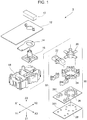
- Fig. 1 is an exploded perspective view of the multidirectional input device 1 according to this embodiment.
- the multidirectional input device 1 includes a knob 10, a panel 12, a second slider 14, a first slider 16, a case 18, a first actuator 20, a second actuator 22, six pressing members 24, an elastic member 26, and a circuit board 28.
- the multidirectional input device 1 functions as an input device that receives multidirectional input performed by sliding and rotating the knob 10.
- the multidirectional input device 1 is used, for example, as a vehicle power seat switch.
- X (X1 and X2) denote three directions perpendicular to each other.
- the X direction corresponds to a second direction of the present invention
- the Y direction corresponds to a first direction of the present invention.
- the panel 12 is depicted as a substantially rectangular member having its longitudinal direction in the Y direction, the shape of the panel 12 is appropriately changed according to the type or the like of product on which the multidirectional input device 1 is mounted, and is not limited to the shape shown in Fig. 1 .
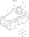
- Fig. 2 is an external view of a main part of the multidirectional input device 1
- Fig. 3 is an external view of the main part with the case 18 omitted
- Fig. 4 is an external view of the main part with the case 18, the first slider 16, and the second slider 14 omitted.
- the first slider 16 and the second slider 14 are disposed on the Z2 direction side of the case 18.
- At least part of a first switch mechanism 30 and a second switch mechanism 32 that include the first actuator 20, the second actuator 22, the pressing members 24, the elastic member 26 (dome portions 261), and the circuit board 28 (contacts 281) is housed in the case 18.
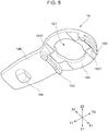
- Fig. 5 is a perspective view of the second slider 14 as viewed from the opposite direction as Fig. 2 .
- the second slider 14 has an annular portion 145 and an extending portion 146, and has a shape substantially like a bottle cap opener as a whole.
- the annular portion 145 has a substantially annular shape and has therein a hole portion 141 that is a through-hole.
- the extending portion 146 has a substantially plate-like shape and extends from the annular portion 145 in the Y1 direction.
- the hole portion 141 has a substantially elliptical shape such that the diameter in the X direction is larger than the diameter in the Y direction.
- the middle part in the X direction of the hole portion 141 slightly bulges in the Y direction.
- the second slider 14 is formed, for example, of insulating synthetic resin.
- a pair of ribs 142 and 143 and a protruding portion 144 that are engaged portions are provided on the back surface (the surface facing the case 18) of the second slider 14.
- the rib 142 is located on the Y2 direction side of the annular portion 145 and extends parallel to the X direction.
- the rib 143 is located on the Y1 direction side of the annular portion 145 (near the boundary between the annular portion 145 and the extending portion 146), and, as with the rib 142, it extends parallel to the X direction.
- the inner surfaces of the ribs 142 and 143 (the Y1 direction side surface of the rib 142 and the Y2 direction side surface of the rib 143) function as engaged surfaces 1421 and 1431 for engaging with the first slider 16.
- the protruding portion 144 is located on the Y1 direction of the extending portion 146 and protrudes in a direction substantially perpendicular to the extending portion 146 (Z1 direction).
- the protruding portion 144 has a substantially semicircular contour as viewed from the Y direction.
- Fig. 6 is a perspective view of the first slider 16.
- the first slider 16 has a substantially cylindrical shaft portion 161, and an engaging portion 162 that is provided at the Z1 direction side (case 18 side) end of the shaft portion 161 and has a substantially rectangular frame shape substantially perpendicular to the shaft portion 161.
- the first slider 16 is formed, for example, of insulating synthetic resin.
- the shaft portion 161 is provided, at both ends in the X direction, with a pair of ribs 1611 and 1612 extending in the Z direction.
- the ribs 1611 and 1612 extend from the base part of the shaft portion 161 (the part connected to the engaging portion 162) to a position of about three-quarters of the full length in the Z direction.
- the engaging portion 162 has engaging surfaces 1621 and 1622 on both sides in the Y direction.
- the engaging surfaces 1621 and 1622 each extend in the X direction.
- the first slider 16 is disposed such that the engaging portion 162 is located on the Z1 direction side of the annular portion 145 of the second slider 14, and the shaft portion 161 protrudes in the Z2 direction through the hole portion 141 in the annular portion 145.
- the engaging surfaces 1621 and 1622 of the engaging portion 162 of the first slider 16 face the engaged surface 1421 of the rib 142 and the engaged surface 1431 of the rib 143 of the second slider 14 with a slight space therebetween.
- Fig. 7 is a perspective view of the case 18, and Fig. 8 is a perspective view of the case 18 as viewed from the opposite direction as Fig. 7 .
- the case 18 has a first case 181 and a second case 182 each having a substantially box shape.
- the first case 181 and the second case 182 are disposed side by side in the Y direction.
- the case 18 is formed, for example, of insulating synthetic resin.
- the first case 181 is open in the Z1 direction, and a top plate portion 1811 on the Z2 direction side is provided with a cross-shaped slit 1813 extending in the X direction and the Y direction.
- the first case 181 has a housing portion 1815 that is formed by four wall portions 1816 extending in the Z1 direction at the four corners of the intersection of the cross shape of the slit 1813.
- the housing portion 1815 houses a main body portion 202 of the first actuator 20 described later such that the first actuator 20 is rockable.
- the second case 182 is open in the Z1 direction, and a top plate portion 1821 on the Z2 direction side is provided with a slit 1823 extending in the X direction.
- the second case 182 is provided with a pair of wall portions 1824 extending in the Z1 direction on both side edges in the Y direction of the slit 1823.
- the substantially middle part in the X direction of each of the wall portions 1824 is recessed in the Z2 direction, and a housing portion 1826 is thereby formed.
- the housing portion 1826 houses a shaft portion 221 of the second actuator 22 described later such that the second actuator 22 is rockable in the X direction.
- the slit 1823 faces the protruding portion 144 of the second slider 14, on the Z2 direction side thereof.
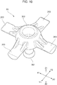
- Fig. 9 is a perspective view of the first actuator 20
- Fig. 10 is a perspective view of the first actuator 20 as viewed from the opposite direction as Fig. 9 .
- the first actuator 20 has a substantially spherical main body portion 202, a substantially cylindrical arm portion 201 extending in the Z2 direction from the main body portion 202, and four leg portions 203 extending in the X1, X2, Y1, and Y2 directions from the main body portion 202.
- the first actuator 20 is formed, for example, of insulating synthetic resin.
- the first actuator 20 is housed in the first case 181 in the X direction and the Y direction, and the arm portion 201 protrudes in the Z2 direction through the slit 1813 of the first case 181.
- the end in the Z2 direction of the arm portion 201 is housed in the end in the Z1 direction of the hollow shaft portion 161 of the first slider 16.
- the main body portion 202 of the first actuator 20 is housed in the housing portion 1815 of the first case 181 such that the first actuator 20 is rockable.
- the first actuator 20 rocks (inclines) in the X direction in response to the movement of the first slider 16 in the X direction, and rocks in the Y direction in response to the movement of the first slider 16 in the Y direction.
- Fig. 11 is a perspective view of the second actuator 22.
- the second actuator 22 has a substantially cylindrical shaft portion 221 having an axis extending in the Y direction, and a pair of wing portions 222 and 223 extending in the X1 direction and the X2 direction from the shaft portion 221.
- the second actuator 22 is formed, for example, of insulating synthetic resin.
- the wing portions 222 and 223 have a substantially inverted V shape as viewed from the Y direction.
- the Z2 direction side surfaces of the wing portions 222 and 223 incline in the Z2 direction from their base parts (parts connected to the shaft portion 221) toward their substantially middle parts in the X1 direction and the X2 direction, and incline in the Z1 direction from their middle parts toward their outer ends.
- the wing portions 222 and 223 of the second actuator 22 have inclined portions 2221 and 2231 corresponding to parts from the base parts to the substantially middle parts in the X direction and inclining in the Z2 direction, and inclined portions 2222 and 2232 corresponding to parts from the substantially middle parts in the X direction to the outer ends and inclining in the Z1 direction.
- the Z2 direction side surface of the shaft portion 221 is recessed in the Z1 direction from the inclined portion 2221 of the wing portion 222 and the inclined portion 2231 of the wing portion 223 on both sides in the X direction, and as a result, a stepped portion 2211 is formed.
- the stepped portion 2211 of the second actuator 22 faces the distal end of the protruding portion 144 of the second slider 14 with a slight space therebetween.
- the second actuator 22 is housed in the second case 182 in the X direction and the Y direction, and parts (ends in the Z direction) of the wing portions 222 and 223 protrude in the Z2 direction through the slit 1823 of the second case 182.
- the shaft portion 221 of the second actuator 22 is housed in the housing portion 1826 of the second case 182 such that the second actuator 22 is rockable in the X direction.
- the second slider 14 moves in the X direction
- the inclined portion 2221 or the inclined portion 2231 is pressed by the protruding portion 144 and the second actuator 22 rocks (inclines) in the X direction.
- the protruding portion 144 moves in the Y direction with its distal end facing the stepped portion 2211 with a slight space therebetween. That is, the second actuator 22 does not rock when the second slider 14 moves in the Y direction.
- one of the pressing members 24 is disposed on the Z1 direction side of each of the four leg portions 203 of the first actuator 20 and the pair of wing portions 222 and 223 of the second actuator 22.
- the pressing members 24 have a substantially bench-like shape having a pair of legs extending in the Z2 direction.
- the pressing members 24 are disposed such that their longitudinal directions are substantially perpendicular to the longitudinal directions of the leg portions 203 and the wing portions 222 and 223.
- two of the dome portions 261 of the elastic member 26 are disposed on the Z1 direction side of each pressing member 24 such that they are arranged side by side in the longitudinal direction of the pressing member 24.
- the dome portions 261 protrude in the Z2 direction.
- the elastic member 26 is formed of various materials having elasticity.
- one of the contacts 281 of the circuit board 28 is located on the Z1 direction side of each dome portion 261 of the elastic member 26. Therefore, when any one of the leg portions 203 is inclined in the Z1 direction with the rocking of the first actuator 20, two of the dome portions 261 are pressed via a corresponding one of the pressing members 24, and as a result, corresponding two of the contacts 281 are turned on or off.
- the first actuator 20, the pressing members 24, the elastic member 26, and the circuit board 28 form the first switch mechanism 30 of the present invention.
- the knob 10 has a substantially box shape.
- the knob 10 is open in the Z1 direction.
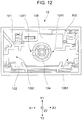
- Fig. 12 is a back view of the knob 10 viewed from the Z2 direction.
- a cylindrical portion 104 having a substantially cylindrical shape and extending in the Z1 direction is provided substantially in the center of the Z1 direction side surface (back surface) of the top plate portion 105 of the knob 10.
- a pair of grooves 1041 extending in the Z direction are formed on both sides in the X direction of the cylindrical portion 104.
- the shaft portion 161 of the first slider 16 is inserted into the cylindrical portion 104. At this time, the ribs 1611 and 1612 of the shaft portion 161 are fitted in the grooves 1041 of the cylindrical portion 104, and the first slider 16 is unrotatably fixed to the knob 10.
- three wall-like restricted members 101, 102, and 103 are formed on the back surface of the top plate portion 105.
- the restricted member 101 is located on the Y1 direction side of the end in the X1 direction
- the restricted member 102 is located at the end in the Y2 direction along the inner wall of the knob 10
- the restricted member 103 is located on the Y1 direction side of the end in the X2 direction.
- a region 1061 is formed by the restricted member 101 and the restricted member 102
- a region 1062 is formed by the restricted member 102 and the restricted member 103.
- Fig. 13 is an enlarged perspective view showing part of the panel 12.
- the panel 12 has a through-hole 121, and restricting members 1221 and 1222 are provided on both sides in the X direction of the through-hole 121.
- the restricting members 1221 and 1222 are members protruding in the Z2 direction, and have a substantially T-shaped contour as viewed from the Z direction.
- the tips of the T-shaped restricting members 1221 and 1222 face outward in the X direction.
- the shaft portion 161 of the first slider 16 is unrotatably fixed to the cylindrical portion 104 of the knob 10 in the through-hole 121 of the panel 12.
- Fig. 14 schematically shows the back surface of the knob 10 when the knob 10 is in its home position. As shown in Fig. 14 , when the knob 10 is in its home position, the restricting members 1221 and 1222 of the panel 12 are located substantially in the centers of the regions 1061 and 1062.
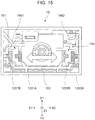
- Fig. 15 schematically shows the back surface of the knob 10 when the knob 10 is slid in the X direction.
- the restricting members 1221 and 1222 relatively move in the X2 direction (restricting members 1221A and 1222A).
- the end in the X2 direction of the substantially T-shaped restricting member 1222A is fitted in a U-shaped region formed by the restricted members 102 and 103, and as a result, the movement of the knob 10 in the X1 direction is limited.
- Parts of the restricted members 101 and 102 are located on both sides in the Y direction of the restricting member 1221A. Therefore, in this state, the knob 10 cannot be slid in the Y direction, and cannot be rotated.
- the restricting members 1221 and 1222 when the knob 10 is slid in the X2 direction, the restricting members 1221 and 1222 relatively move in the X1 direction (restricting members 1221B and 1222B). At this time, the end in the X1 direction of the substantially T-shaped restricting member 1221B is fitted in a U-shaped region formed by the restricted members 101 and 102, and as a result, the movement of the knob 10 in the X2 direction is limited. Parts of the restricted members 101 and 103 are located on both sides in the Y direction of the restricting member 1222B. Therefore, in this state, the knob 10 cannot be slid in the Y direction, and cannot be rotated.
- Fig. 16 schematically shows the back surface of the knob 10 when the knob 10 is slid in the Y direction.
- the restricting members 1221 and 1222 relatively move in the Y2 direction (restricting members 1221C and 1222C).
- the ends in the Y2 direction of the restricting members 1221C and 1222C come into contact with the restricted member 102.
- the movement of the knob 10 in the Y1 direction is limited.
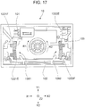
- Fig. 17 schematically shows the back surface of the knob 10 when the knob 10 is rotated.
- the restricting member 1221 relatively moves in the Y2 direction (1221E)
- the restricting member 1222 relatively moves in the Y1 direction (1222E).
- the restricting member 1221E comes into contact with the restricted member 102
- the restricting member 1222E comes into contact with the restricted member 103.
- the rotation of the knob 10 in the R1 direction is limited.
- the knob 10 receives sliding operation and rotational operation in the X direction and the Y direction within the above-described range of movement.
- the first slider 16 which operates integrally with the knob 10 also moves in the X direction.
- the second slider 14 since the engaged surfaces 1421 and 1431 of the second slider 14, and the engaging surfaces 1621 and 1622 of the first slider 16 are both parallel to the X direction, the second slider 14 does not engage with the first slider 16.
- the first slider 16 moves in the X direction
- the end in the Z2 direction of the arm portion 201 of the first actuator 20 moves in the X direction, and the first actuator 20 rocks and inclines in the X1 direction or the X2 direction.
- corresponding contacts 281 are pressed via corresponding pressing member 24 and elastic member 26 (dome portions 261) and turned on or off.
- the first slider 16 which operates integrally with the knob 10 also moves in the Y direction.
- the engaging surfaces 1621 and 1622 of the engaging portion 162 of the first slider 16 engage with the engaged surfaces 1421 and 1431 of the ribs 142 and 143 of the second slider 14.
- the second slider 14 also moves in the Y direction.
- the first slider 16 which operates integrally with the knob 10 also rotates about the shaft portion 161.
- the engaging surfaces 1621 and 1622 of the engaging portion 162 of the first slider 16 engage with the engaged surfaces 1421 and 1431 of the ribs 142 and 143 of the second slider 14.
- the second slider 14 also rotates about the shaft portion 161.
- the protruding portion 144 moves in the X direction and presses the inclined portion 2221 or 2231, and the second actuator 22 rocks and inclines in the X1 direction or the X2 direction.
- the second actuator 22 inclines, corresponding contacts 281 are pressed via corresponding pressing member 24 and elastic member 26 (dome portions 261) and turned on or off.
- the first slider 16 rotates, the first actuator 20 does not operate because the first actuator 20 is rotatably connected to the first slider 16.
- the first actuator 20 and the second actuator 22 that are inclined in response to the operation of the knob 10 are returned to their home positions by the elastic force in the Z2 direction of the dome portions 261 of the elastic member 26 when the knob 10 is released from the operation.
- first slider 16 and the second slider 14 are illustrative, and the first slider and the second slider can have various shapes.
- first actuator 20 and the second actuator 22 are illustrative, and the first actuator and the second actuator can have various shapes.
- the configurations of the first switch mechanism and the second switch mechanism are not limited to those described above, and the first switch mechanism and the second switch mechanism can have various configurations.
- moving contacts facing the contacts 281 may be provided on the Z1 direction side of the dome portions 261 so that when the dome portions 261 are pressed, the contacts 281 come into contact with the moving contacts.
- the present invention can be applied, for example, to a vehicle power seat switch.
Description
- The present invention relates to multidirectional input devices with which multidirectional input operation can be performed.
- Hitherto, devices with which multidirectional input operation can be performed, such as a vehicle power seat switch, have been known. For example, a switch device disclosed in Japanese Unexamined Patent Application Publication No.
2004-288393 -
DE 10 2010 012908 A1 discloses an electric multi-function switch capable of performing a linear direction operation and a rotational direction operation with one operation body. -
EP 2 631 108 A1 discloses a control device for seat adjustment. The control device comprises a control knob which is movably mounted onto the carrier, actuating levers to be controlled by the displacement of the control knob relative to said carrier in order to cause switching contacts to be actuated, said control knob being displaceable along a first transverse direction towards an actuated position, and said control knob being able to be turned on a main axis (X1) towards a first pivoted position, characterized in that the control knob is connected to an actuating arm which pivots, relative to the carrier, only when the control knob is turned on the main axis (X1) towards its pivoted position, said actuating arm, when pivoted, causing additional switching contacts to be actuated. - The present invention relates to a multidirectional input device in accordance with the appended claims.
- However, in a conventional switch device such as that described above, an operation knob for sliding operation and an operation knob for rotational operation are separately provided, and therefore the operation is complicated. In addition, such a plurality of operation knobs increase the size of the whole device, and also increase the cost. Thus, conventional multidirectional input devices can have various disadvantages due to the fact that a knob for sliding operation and a knob for rotational operation are separately provided.
- The present invention is made in view of such circumstances, and provides a multidirectional input device such that input by sliding operation and rotational operation can be performed with a single knob.
- In an aspect of the present invention, a multidirectional input device includes a knob that receives sliding operation in a first direction and a second direction perpendicular to each other and rotational operation about an axis of rotation perpendicular to the first direction and the second direction, a first slider that operates integrally with the knob, a first switch mechanism having a plurality of contacts that are each turned on or off in response to the displacement of the first slider in the first direction or the second direction, a second slider that operates by engaging with the first slider rotating in response to the rotational operation and the first slider moving in the first direction in response to the sliding operation, but does not engage with the first slider moving in the second direction in response to the sliding operation, and a second switch mechanism having at least one contact that is turned on or off in response to the displacement of the second slider operating by engaging with the first slider rotating, and keeps being turned on or off despite the displacement of the second slider operating by engaging with the first slider moving in the first direction.
- With this configuration, since the first switch mechanism that is turned on or off in response to the sliding operation of the knob, and the second switch mechanism that is turned on or off in response to the rotational operation of the knob are provided, input by sliding operation and rotational operation can be performed with a single knob. As a result, compared to a configuration having a plurality of knobs, an increase in the size of the whole device and an increase in cost are suppressed.
- It is preferable that the first slider have a shaft portion connected to the knob and extending along the axis of rotation, and an engaging portion with which the shaft portion is provided, and the second slider have an engaged portion that engages with the engaging portion of the first slider rotating in response to the rotational operation and the engaging portion of the first slider moving in the first direction in response to the sliding operation.
- With this configuration, the first slider and the second slider can be engaged with each other by means of the engaging portion of the first slider and the engaged portion of the second slider.
- It is preferable that the engaging portion of the first slider have an engaging surface extending parallel to the second direction, and the engaged portion of the second slider face the engaging surface of the engaging portion.
- With this configuration, since the engaging surface of the engaging portion of the first slider extends parallel to the second direction, the engaging portion of the first slider can be prevented from engaging with the engaged portion of the second slider when the first slider moves in the second direction in response to sliding operation.
- It is preferable that the engaged portion of the second slider be a rib having an engaged surface extending parallel to the second direction.
- With this configuration, when the first slider moves in the first direction, the engaged surface extending parallel to the second direction and the engaging surface extending parallel to the second direction can be reliably engaged with each other, and, when the first slider moves in the second direction, the engaged surface and the engaging surface can be prevented from engaging with each other.
- It is preferable that the knob be connected to one end of the shaft portion, the engaging portion be provided at the other end of the shaft portion, and the second slider have a hole portion through which the shaft portion is passed between the knob and the engaging portion.
- With this configuration, the first slider and the second slider can be disposed such that the shaft portion of the first slider is passed through the hole portion of the second slider.
- It is preferable that the first switch mechanism have a first actuator that rocks in the first direction and the second direction in response to the displacement of the first slider in the first direction and the second direction, and each of the plurality of contacts of the first switch mechanism be turned on or off in response to the rocking of the first actuator.
- With this configuration, the first switch mechanism can be formed using the first actuator that rocks in response to the sliding operation of the knob.
- It is preferable that the first slider be connected to the first actuator so as to be rotatable relative to the first actuator in response to the rotational operation.
- With this configuration, the first actuator can be prevented from operating when the knob is rotated.
- It is preferable that the first switch mechanism have a plurality of pressing members that each press at least one of the plurality of contacts of the first switch mechanism in response to the rocking of the first actuator, and each of the plurality of contacts of the first switch mechanism be turned on or off in response to the pressing by the pressing members.
- With this configuration, the first switch mechanism can be formed using the pressing member that presses the contact in response to the rocking of the first actuator.
- It is preferable that the second switch mechanism have a second actuator that rocks in response to the displacement of the second slider operating by engaging with the first slider rotating, but does not rock in response to the displacement of the second slider operating by engaging with the first slider moving in the first direction, and the at least one contact of the second switch mechanism be turned on or off in response to the rocking of the second actuator.
- With this configuration, the second switch mechanism can be formed using the second actuator that rocks in response to the rotational operation of the knob but does not rock in response to sliding operation.
- It is preferable that the second slider have a protruding portion that faces the second actuator and protrudes toward the second actuator, and the second actuator rock by being pressed by the protruding portion of the second slider operating by engaging with the first slider rotating.
- With this configuration, the second actuator can be rocked by the protruding portion of the second slider.
- It is preferable that the second slider rotate by engaging with the first slider rotating, and move in the first direction by engaging with the first slider moving in the first direction, and the second actuator rock in the second direction by being pressed by the protruding portion of the second slider rotating, but does not pressed by the protruding portion of the second slider moving in the first direction.
- With this configuration, the second actuator can be rocked by being pressed by the protruding portion when the second slider rotates, and can be prevented from being pressed by the protruding portion when the second slider moves in the first direction.
- It is preferable that the second actuator have, on its surface facing the protruding portion, an inclined portion that inclines in the second direction, and the inclined portion be pressed by the protruding portion of the second slider rotating and rock in the second direction.
- With this configuration, the protruding portion of the second slider can press the inclined portion of the second actuator in response to the displacement in the second direction of the second slider rotating.
- It is preferable that the second switch mechanism have at least one pressing member that presses the at least one contact of the second switch mechanism in response to the rocking of the second actuator, and the at least one contact of the second switch mechanism be turned on or off in response to the pressing by the pressing member.
- With this configuration, the second switch mechanism can be formed using the pressing member that presses the contact in response to the rocking of the second actuator.
- It is preferable that the first switch mechanism and the second switch mechanism be disposed side by side in the first direction, the first slider be located on the knob side of the first switch mechanism, and the second slider be located on the knob side of the first switch mechanism and the second switch mechanism, and have a shape having its longitudinal direction in the first direction.
- With this configuration, the first switch mechanism and the second switch mechanism can be disposed side by side in the first direction.
- It is preferable that the multidirectional input device include a panel located between the knob and the first slider, and the range of movement of the knob be restricted by a restricted member provided on the panel side of the knob and a restricting member provided on the knob side of the panel.
- With this configuration, the range of movement of the knob can be restricted.
- It is preferable that when the knob is displaced in the first direction in response to the sliding operation in the first direction, at least part of the restricting member of the panel is located on both sides in the second direction.
- With this configuration, since, when the knob is displaced in the first direction, the movement in the second direction is restricted by the restricting member of the panel located on both sides in the second direction, sliding operation and rotational operation in the second direction when sliding operation in the first direction is performed can be limited.
- The present invention can provide a multidirectional input device such that input by sliding operation and rotational operation can be performed with a single knob.
-
-
Fig. 1 is an exploded perspective view of a multidirectional input device according to an embodiment of the present invention; -
Fig. 2 is an external view of a main part of the multidirectional input device; -
Fig. 3 is an external view of the main part with a case omitted; -
Fig. 4 is an external view of the main part with the case, a first slider, and a second slider omitted; -
Fig. 5 is a perspective view of thesecond slider 14 as viewed from the opposite direction asFig. 2 ; -
Fig. 6 is a perspective view of the first slider; -
Fig. 7 is a perspective view of the case; -
Fig. 8 is a perspective view of the case as viewed from the opposite direction asFig. 7 ; -
Fig. 9 is a perspective view of a first actuator; -
Fig. 10 is a perspective view of the first actuator as viewed from the opposite direction asFig. 9 ; -
Fig. 11 is a perspective view of a second actuator; -
Fig. 12 is a back view of a knob; -
Fig. 13 is an enlarged perspective view showing part of a panel; -
Fig. 14 schematically shows the back surface of the knob when the knob is in its home position; -
Fig. 15 schematically shows the back surface of the knob when the knob is slid in the X direction; -
Fig. 16 schematically shows the back surface of the knob when the knob is slid in the Y direction; and -
Fig. 17 schematically shows the back surface of the knob when the knob is rotated. - A multidirectional input device according to an embodiment of the present invention will be described below.
Fig. 1 is an exploded perspective view of themultidirectional input device 1 according to this embodiment. As shown inFig. 1 , themultidirectional input device 1 includes aknob 10, apanel 12, asecond slider 14, afirst slider 16, acase 18, afirst actuator 20, asecond actuator 22, six pressingmembers 24, anelastic member 26, and acircuit board 28. Themultidirectional input device 1 functions as an input device that receives multidirectional input performed by sliding and rotating theknob 10. Themultidirectional input device 1 is used, for example, as a vehicle power seat switch. - "X (X1 and X2)," "Y (Y1 and Y2)," and "Z (Z1 and Z2)" in
Fig. 1 and subsequent figures denote three directions perpendicular to each other. The X direction corresponds to a second direction of the present invention, and the Y direction corresponds to a first direction of the present invention. - Although, in
Fig. 1 , thepanel 12 is depicted as a substantially rectangular member having its longitudinal direction in the Y direction, the shape of thepanel 12 is appropriately changed according to the type or the like of product on which themultidirectional input device 1 is mounted, and is not limited to the shape shown inFig. 1 . -
Fig. 2 is an external view of a main part of themultidirectional input device 1,Fig. 3 is an external view of the main part with thecase 18 omitted, andFig. 4 is an external view of the main part with thecase 18, thefirst slider 16, and thesecond slider 14 omitted. As shown inFig. 2 to Fig. 4 , in themultidirectional input device 1, thefirst slider 16 and thesecond slider 14 are disposed on the Z2 direction side of thecase 18. At least part of afirst switch mechanism 30 and asecond switch mechanism 32 that include thefirst actuator 20, thesecond actuator 22, thepressing members 24, the elastic member 26 (dome portions 261), and the circuit board 28 (contacts 281) is housed in thecase 18. -
Fig. 5 is a perspective view of thesecond slider 14 as viewed from the opposite direction asFig. 2 . As shown inFig. 5 , thesecond slider 14 has anannular portion 145 and an extendingportion 146, and has a shape substantially like a bottle cap opener as a whole. Theannular portion 145 has a substantially annular shape and has therein ahole portion 141 that is a through-hole. The extendingportion 146 has a substantially plate-like shape and extends from theannular portion 145 in the Y1 direction. Thehole portion 141 has a substantially elliptical shape such that the diameter in the X direction is larger than the diameter in the Y direction. The middle part in the X direction of thehole portion 141 slightly bulges in the Y direction. Thesecond slider 14 is formed, for example, of insulating synthetic resin. - As shown in
Fig. 5 , a pair ofribs portion 144 that are engaged portions are provided on the back surface (the surface facing the case 18) of thesecond slider 14. Therib 142 is located on the Y2 direction side of theannular portion 145 and extends parallel to the X direction. Therib 143 is located on the Y1 direction side of the annular portion 145 (near the boundary between theannular portion 145 and the extending portion 146), and, as with therib 142, it extends parallel to the X direction. The inner surfaces of theribs 142 and 143 (the Y1 direction side surface of therib 142 and the Y2 direction side surface of the rib 143) function as engagedsurfaces first slider 16. - As shown in
Fig. 5 , the protrudingportion 144 is located on the Y1 direction of the extendingportion 146 and protrudes in a direction substantially perpendicular to the extending portion 146 (Z1 direction). The protrudingportion 144 has a substantially semicircular contour as viewed from the Y direction. -
Fig. 6 is a perspective view of thefirst slider 16. As shown inFig. 6 , thefirst slider 16 has a substantiallycylindrical shaft portion 161, and an engagingportion 162 that is provided at the Z1 direction side (case 18 side) end of theshaft portion 161 and has a substantially rectangular frame shape substantially perpendicular to theshaft portion 161. Thefirst slider 16 is formed, for example, of insulating synthetic resin. - As shown in
Fig. 6 , theshaft portion 161 is provided, at both ends in the X direction, with a pair ofribs ribs - As shown in
Fig. 6 , the engagingportion 162 has engagingsurfaces surfaces - As shown in
Fig. 2 andFig. 3 , thefirst slider 16 is disposed such that the engagingportion 162 is located on the Z1 direction side of theannular portion 145 of thesecond slider 14, and theshaft portion 161 protrudes in the Z2 direction through thehole portion 141 in theannular portion 145. The engagingsurfaces portion 162 of thefirst slider 16 face the engagedsurface 1421 of therib 142 and the engagedsurface 1431 of therib 143 of thesecond slider 14 with a slight space therebetween. -
Fig. 7 is a perspective view of thecase 18, andFig. 8 is a perspective view of thecase 18 as viewed from the opposite direction asFig. 7 . As shown inFig. 7 andFig. 8 , thecase 18 has afirst case 181 and asecond case 182 each having a substantially box shape. Thefirst case 181 and thesecond case 182 are disposed side by side in the Y direction. Thecase 18 is formed, for example, of insulating synthetic resin. - As shown in
Fig. 7 andFig. 8 , thefirst case 181 is open in the Z1 direction, and atop plate portion 1811 on the Z2 direction side is provided with across-shaped slit 1813 extending in the X direction and the Y direction. A shown inFig. 8 , thefirst case 181 has ahousing portion 1815 that is formed by fourwall portions 1816 extending in the Z1 direction at the four corners of the intersection of the cross shape of theslit 1813. Thehousing portion 1815 houses amain body portion 202 of thefirst actuator 20 described later such that thefirst actuator 20 is rockable. - As shown in
Fig. 7 andFig. 8 , thesecond case 182 is open in the Z1 direction, and atop plate portion 1821 on the Z2 direction side is provided with aslit 1823 extending in the X direction. As shown inFig. 8 , thesecond case 182 is provided with a pair ofwall portions 1824 extending in the Z1 direction on both side edges in the Y direction of theslit 1823. The substantially middle part in the X direction of each of thewall portions 1824 is recessed in the Z2 direction, and ahousing portion 1826 is thereby formed. Thehousing portion 1826 houses ashaft portion 221 of thesecond actuator 22 described later such that thesecond actuator 22 is rockable in the X direction. As is clear, for example, fromFig. 2 andFig. 3 , theslit 1823 faces the protrudingportion 144 of thesecond slider 14, on the Z2 direction side thereof. -
Fig. 9 is a perspective view of thefirst actuator 20, andFig. 10 is a perspective view of thefirst actuator 20 as viewed from the opposite direction asFig. 9 . As shown inFig. 9 andFig. 10 , thefirst actuator 20 has a substantially sphericalmain body portion 202, a substantiallycylindrical arm portion 201 extending in the Z2 direction from themain body portion 202, and fourleg portions 203 extending in the X1, X2, Y1, and Y2 directions from themain body portion 202. Thefirst actuator 20 is formed, for example, of insulating synthetic resin. - As is clear, for example, from
Fig. 2 to Fig. 4 , thefirst actuator 20 is housed in thefirst case 181 in the X direction and the Y direction, and thearm portion 201 protrudes in the Z2 direction through theslit 1813 of thefirst case 181. The end in the Z2 direction of thearm portion 201 is housed in the end in the Z1 direction of thehollow shaft portion 161 of thefirst slider 16. As described above, themain body portion 202 of thefirst actuator 20 is housed in thehousing portion 1815 of thefirst case 181 such that thefirst actuator 20 is rockable. As a result, thefirst actuator 20 rocks (inclines) in the X direction in response to the movement of thefirst slider 16 in the X direction, and rocks in the Y direction in response to the movement of thefirst slider 16 in the Y direction. -
Fig. 11 is a perspective view of thesecond actuator 22. As shown inFig. 11 , thesecond actuator 22 has a substantiallycylindrical shaft portion 221 having an axis extending in the Y direction, and a pair ofwing portions shaft portion 221. Thesecond actuator 22 is formed, for example, of insulating synthetic resin. - As shown in
Fig. 11 , thewing portions wing portions wing portions second actuator 22 have inclinedportions inclined portions - As shown in
Fig. 11 , the Z2 direction side surface of theshaft portion 221 is recessed in the Z1 direction from theinclined portion 2221 of thewing portion 222 and theinclined portion 2231 of thewing portion 223 on both sides in the X direction, and as a result, a steppedportion 2211 is formed. - As shown in
Fig. 3 , the steppedportion 2211 of thesecond actuator 22 faces the distal end of the protrudingportion 144 of thesecond slider 14 with a slight space therebetween. As is clear, for example, fromFig. 2 to Fig. 4 , thesecond actuator 22 is housed in thesecond case 182 in the X direction and the Y direction, and parts (ends in the Z direction) of thewing portions slit 1823 of thesecond case 182. As described above, theshaft portion 221 of thesecond actuator 22 is housed in thehousing portion 1826 of thesecond case 182 such that thesecond actuator 22 is rockable in the X direction. As a result, when thesecond slider 14 moves in the X direction, theinclined portion 2221 or theinclined portion 2231 is pressed by the protrudingportion 144 and thesecond actuator 22 rocks (inclines) in the X direction. On the other hand, when thesecond slider 14 moves in the Y direction, the protrudingportion 144 moves in the Y direction with its distal end facing the steppedportion 2211 with a slight space therebetween. That is, thesecond actuator 22 does not rock when thesecond slider 14 moves in the Y direction. - As shown in
Fig. 4 , one of thepressing members 24 is disposed on the Z1 direction side of each of the fourleg portions 203 of thefirst actuator 20 and the pair ofwing portions second actuator 22. Thepressing members 24 have a substantially bench-like shape having a pair of legs extending in the Z2 direction. Thepressing members 24 are disposed such that their longitudinal directions are substantially perpendicular to the longitudinal directions of theleg portions 203 and thewing portions - As shown in
Fig. 3 andFig. 4 , two of thedome portions 261 of theelastic member 26 are disposed on the Z1 direction side of each pressingmember 24 such that they are arranged side by side in the longitudinal direction of the pressingmember 24. Thedome portions 261 protrude in the Z2 direction. Theelastic member 26 is formed of various materials having elasticity. - As shown in
Fig. 1 , one of thecontacts 281 of thecircuit board 28 is located on the Z1 direction side of eachdome portion 261 of theelastic member 26. Therefore, when any one of theleg portions 203 is inclined in the Z1 direction with the rocking of thefirst actuator 20, two of thedome portions 261 are pressed via a corresponding one of thepressing members 24, and as a result, corresponding two of thecontacts 281 are turned on or off. Thus, thefirst actuator 20, thepressing members 24, theelastic member 26, and thecircuit board 28 form thefirst switch mechanism 30 of the present invention. - When any one of the
wing portions second actuator 22, two of thedome portions 261 are pressed via a corresponding one of thepressing members 24, and as a result, corresponding two of thecontacts 281 are turned on or off. Thus, thesecond actuator 22, thepressing members 24, theelastic member 26, and thecircuit board 28 form thesecond switch mechanism 32 of the present invention. - As shown in
Fig. 1 , theknob 10 has a substantially box shape. Theknob 10 is open in the Z1 direction.Fig. 12 is a back view of theknob 10 viewed from the Z2 direction. Acylindrical portion 104 having a substantially cylindrical shape and extending in the Z1 direction is provided substantially in the center of the Z1 direction side surface (back surface) of thetop plate portion 105 of theknob 10. A pair ofgrooves 1041 extending in the Z direction are formed on both sides in the X direction of thecylindrical portion 104. Theshaft portion 161 of thefirst slider 16 is inserted into thecylindrical portion 104. At this time, theribs shaft portion 161 are fitted in thegrooves 1041 of thecylindrical portion 104, and thefirst slider 16 is unrotatably fixed to theknob 10. - As shown in
Fig. 12 , three wall-likerestricted members top plate portion 105. On the back surface of thetop plate portion 105, the restrictedmember 101 is located on the Y1 direction side of the end in the X1 direction, the restrictedmember 102 is located at the end in the Y2 direction along the inner wall of theknob 10, and the restrictedmember 103 is located on the Y1 direction side of the end in the X2 direction. Aregion 1061 is formed by the restrictedmember 101 and the restrictedmember 102, and aregion 1062 is formed by the restrictedmember 102 and the restrictedmember 103. -
Fig. 13 is an enlarged perspective view showing part of thepanel 12. As shown inFig. 13 , thepanel 12 has a through-hole 121, and restrictingmembers hole 121. The restrictingmembers members shaft portion 161 of thefirst slider 16 is unrotatably fixed to thecylindrical portion 104 of theknob 10 in the through-hole 121 of thepanel 12. - With reference to
Fig. 14 to Fig. 17 , the operation will be described in which the range of movement of theknob 10 is restricted by the restrictedmembers knob 10 and the restrictingmembers panel 12. -
Fig. 14 schematically shows the back surface of theknob 10 when theknob 10 is in its home position. As shown inFig. 14 , when theknob 10 is in its home position, the restrictingmembers panel 12 are located substantially in the centers of theregions -
Fig. 15 schematically shows the back surface of theknob 10 when theknob 10 is slid in the X direction. As shown inFig. 15 , when theknob 10 is slid in the X1 direction, the restrictingmembers members member 1222A is fitted in a U-shaped region formed by the restrictedmembers knob 10 in the X1 direction is limited. Parts of the restrictedmembers member 1221A. Therefore, in this state, theknob 10 cannot be slid in the Y direction, and cannot be rotated. - Similarly, as shown in
Fig. 15 , when theknob 10 is slid in the X2 direction, the restrictingmembers members member 1221B is fitted in a U-shaped region formed by the restrictedmembers knob 10 in the X2 direction is limited. Parts of the restrictedmembers member 1222B. Therefore, in this state, theknob 10 cannot be slid in the Y direction, and cannot be rotated. -
Fig. 16 schematically shows the back surface of theknob 10 when theknob 10 is slid in the Y direction. As shown inFig. 16 , when theknob 10 is slid in the Y1 direction, the restrictingmembers members members member 102. As a result, the movement of theknob 10 in the Y1 direction is limited. - Similarly, as shown in
Fig. 16 , when theknob 10 is slid in the Y2 direction, the restrictingmembers members members members knob 10 in the Y2 direction is limited. -
Fig. 17 schematically shows the back surface of theknob 10 when theknob 10 is rotated. As shown inFig. 17 , when theknob 10 is rotated in the R1 direction, the restrictingmember 1221 relatively moves in the Y2 direction (1221E), and the restrictingmember 1222 relatively moves in the Y1 direction (1222E). At this time, the restrictingmember 1221E comes into contact with the restrictedmember 102, and the restrictingmember 1222E comes into contact with the restrictedmember 103. As a result, the rotation of theknob 10 in the R1 direction is limited. - Similarly, as shown in
Fig. 17 , when theknob 10 is rotated in the R2 direction, the restrictingmember 1221 relatively moves in the Y1 direction (1221F), and the restrictingmember 1222 relatively moves in the Y2 direction (1222F). At this time, the restrictingmember 1221F comes into contact with the restrictedmember 101, and the restrictingmember 1222F comes into contact with the restrictedmember 102. As a result, the rotation of theknob 10 in the R2 direction is limited. - In the thus configured
multidirectional input device 1, theknob 10 receives sliding operation and rotational operation in the X direction and the Y direction within the above-described range of movement. When theknob 10 is slid in the X direction, thefirst slider 16, which operates integrally with theknob 10, also moves in the X direction. At this time, since the engagedsurfaces second slider 14, and the engagingsurfaces first slider 16 are both parallel to the X direction, thesecond slider 14 does not engage with thefirst slider 16. When thefirst slider 16 moves in the X direction, the end in the Z2 direction of thearm portion 201 of thefirst actuator 20 moves in the X direction, and thefirst actuator 20 rocks and inclines in the X1 direction or the X2 direction. When thefirst actuator 20 inclines,corresponding contacts 281 are pressed via corresponding pressingmember 24 and elastic member 26 (dome portions 261) and turned on or off. - When the
knob 10 is slid in the Y direction, thefirst slider 16, which operates integrally with theknob 10, also moves in the Y direction. At this time, the engagingsurfaces portion 162 of thefirst slider 16 engage with the engagedsurfaces ribs second slider 14. As a result, thesecond slider 14 also moves in the Y direction. - When the
first slider 16 moves in the Y direction, the end in the Z2 direction of thearm portion 201 of thefirst actuator 20 moves in the Y direction, and thefirst actuator 20 rocks and inclines in the Y1 direction or the Y2 direction. When thefirst actuator 20 inclines,corresponding contacts 281 are pressed via corresponding pressingmember 24 and elastic member 26 (dome portions 261) and turned on or off. On the other hand, when thesecond slider 14 moves in the Y direction, the protrudingportion 144 of thesecond slider 14 moves in the Y direction with its distal end facing the steppedportion 2211 with a slight space therebetween, and therefore thesecond actuator 22 does not operate. - When the
knob 10 is rotated, thefirst slider 16, which operates integrally with theknob 10, also rotates about theshaft portion 161. At this time, the engagingsurfaces portion 162 of thefirst slider 16 engage with the engagedsurfaces ribs second slider 14. As a result, thesecond slider 14 also rotates about theshaft portion 161. - When the
second slider 14 rotates, the protrudingportion 144 moves in the X direction and presses theinclined portion second actuator 22 rocks and inclines in the X1 direction or the X2 direction. When thesecond actuator 22 inclines,corresponding contacts 281 are pressed via corresponding pressingmember 24 and elastic member 26 (dome portions 261) and turned on or off. On the other hand, when thefirst slider 16 rotates, thefirst actuator 20 does not operate because thefirst actuator 20 is rotatably connected to thefirst slider 16. - The
first actuator 20 and thesecond actuator 22 that are inclined in response to the operation of theknob 10 are returned to their home positions by the elastic force in the Z2 direction of thedome portions 261 of theelastic member 26 when theknob 10 is released from the operation. - For example, the shapes of the
first slider 16 and thesecond slider 14 are illustrative, and the first slider and the second slider can have various shapes. - The shapes of the
first actuator 20 and thesecond actuator 22 are illustrative, and the first actuator and the second actuator can have various shapes. The configurations of the first switch mechanism and the second switch mechanism are not limited to those described above, and the first switch mechanism and the second switch mechanism can have various configurations. For example, moving contacts facing thecontacts 281 may be provided on the Z1 direction side of thedome portions 261 so that when thedome portions 261 are pressed, thecontacts 281 come into contact with the moving contacts. - The present invention can be applied, for example, to a vehicle power seat switch.
Claims (16)
- A multidirectional input device (1) comprising:a knob (10) that receives sliding operation in a first direction and a second direction perpendicular to each other and rotational operation about an axis of rotation perpendicular to the first direction and the second direction; anda first slider (16) that operates integrally with the knob (10);characterized bya first switch mechanism (30) having a plurality of contacts (281) that are each turned on or off in response to the displacement of the first slider (16) in the first direction or the second direction;a second slider (14) that operates by engaging with the first slider (16) rotating in response to the rotational operation and the first slider (16) moving in the first direction in response to the sliding operation, but does not engage with the first slider (16) moving in the second direction in response to the sliding operation; anda second switch mechanism (32) having at least one contact (281) that is turned on or off in response to the displacement of the second slider (14) operating by engaging with the first slider (16) rotating, and keeps being turned on or off despite the displacement of the second slider (14) operating by engaging with the first slider (16) moving in the first direction.
- The multidirectional input device (1) according to Claim 1,
wherein the first slider (16) has a shaft portion (161) connected to the knob (10) and extending along the axis of rotation, and an engaging portion (162) with which the shaft portion (161) is provided, and
wherein the second slider (14) has an engaged portion (142, 143) that engages with the engaging portion (162) of the first slider (16) rotating in response to the rotational operation and the engaging portion (162) of the first slider (16) moving in the first direction in response to the sliding operation. - The multidirectional input device (1) according to Claim 2,
wherein the engaging portion (162) of the first slider (16) has an engaging surface (1621, 1622) extending parallel to the second direction, and
wherein the engaged portion (142, 143) of the second slider (14) faces the engaging surface (1621, 1622) of the engaging portion (162). - The multidirectional input device (1) according to Claim 3, wherein the engaged portion (142, 143) of the second slider (14) is a rib having an engaged surface extending parallel to the second direction.
- The multidirectional input device (1) according to any one of Claims 2 to 4,
wherein the knob (10) is connected to one end of the shaft portion (161),
wherein the engaging portion (162) is provided at the other end of the shaft portion (161), and
wherein the second slider (14) has a hole portion (141) through which the shaft portion (161) is passed between the knob (10) and the engaging portion (162). - The multidirectional input device (1) according to any one of Claims 1 to 5,
wherein the first switch mechanism (30) has a first actuator (20) that rocks in the first direction and the second direction in response to the displacement of the first slider (16) in the first direction and the second direction, and
wherein each of the plurality of contacts (281) of the first switch mechanism (30) is turned on or off in response to the rocking of the first actuator (20). - The multidirectional input device (1) according to Claim 6, wherein the first slider (16) is connected to the first actuator (20) so as to be rotatable relative to the first actuator (20) in response to the rotational operation.
- The multidirectional input device (1) according to Claim 6 or 7,
wherein the first switch mechanism (30) has a plurality of pressing members (24) that each press at least one of the plurality of contacts (281) of the first switch mechanism (30) in response to the rocking of the first actuator (20), and
wherein each of the plurality of contacts (281) of the first switch mechanism (30) is turned on or off in response to the pressing by the pressing members (24). - The multidirectional input device (1) according to any one of Claims 1 to 8,
wherein the second switch mechanism (32) has a second actuator (22) that rocks in response to the displacement of the second slider (14) operating by engaging with the first slider (16) rotating, but does not rock in response to the displacement of the second slider (14) operating by engaging with the first slider (16) moving in the first direction, and
wherein the at least one contact (281) of the second switch mechanism (32) is turned on or off in response to the rocking of the second actuator (22). - The multidirectional input device (1) according to Claim 9,
wherein the second slider (14) has a protruding portion (144) that faces the second actuator (22) and protrudes toward the second actuator (22), and
wherein the second actuator (22) rocks by being pressed by the protruding portion (144) of the second slider (14) operating by engaging with the first slider (16) rotating. - The multidirectional input device (1) according to Claim 10,
wherein the second slider (14) rotates by engaging with the first slider (16) rotating, and moves in the first direction by engaging with the first slider (16) moving in the first direction, and
wherein the second actuator (22) rocks in the second direction by being pressed by the protruding portion (144) of the second slider (14) rotating, but does not pressed by the protruding portion (144) of the second slider (14) moving in the first direction. - The multidirectional input device (1) according to Claim 11,
wherein the second actuator (22) has, on its surface facing the protruding portion (144), an inclined portion that inclines in the second direction, and the inclined portion is pressed by the protruding portion (144) of the second slider (14) rotating and rocks in the second direction. - The multidirectional input device (1) according to any one of Claims 9 to 12,
wherein the second switch mechanism (32) has at least one pressing member (24) that presses the at least one contact (281) of the second switch mechanism (32) in response to the rocking of the second actuator (22), and
wherein the at least one contact (281) of the second switch mechanism (32) is turned on or off in response to the pressing by the pressing member (24). - The multidirectional input device (1) according to any one of Claims 1 to 13,
wherein the first switch mechanism (30) and the second switch mechanism (32) are disposed side by side in the first direction,
wherein the first slider (16) is located on the knob (10) side of the first switch mechanism (30), and
wherein the second slider (14) is located on the knob (10) side of the first switch mechanism (30) and the second switch mechanism (32), and has a shape having its longitudinal direction in the first direction. - The multidirectional input device (1) according to any one of Claims 1 to 14,
further comprising a panel (12) located between the knob (10) and the first slider (16),
wherein the range of movement of the knob (10) is restricted by a restricted member (101, 102, 103) provided on the panel (12) side of the knob (10) and a restricting member (1221, 1222) provided on the knob (10) side of the panel (12). - The multidirectional input device (1) according to Claim 15,
wherein the restricted member (101, 102, 103) of the knob (10) is such that when the knob (10) is displaced in the first direction in response to the sliding operation in the first direction, at least part of the restricting member (1221, 1222) of the panel (12) is located on both sides in the second direction.
Applications Claiming Priority (1)
| Application Number | Priority Date | Filing Date | Title |
|---|---|---|---|
| JP2016038692A JP6651385B2 (en) | 2016-03-01 | 2016-03-01 | Multi-directional input device |
Publications (2)
| Publication Number | Publication Date |
|---|---|
| EP3214632A1 EP3214632A1 (en) | 2017-09-06 |
| EP3214632B1 true EP3214632B1 (en) | 2019-08-21 |
Family
ID=58108535
Family Applications (1)
| Application Number | Title | Priority Date | Filing Date |
|---|---|---|---|
| EP17157419.7A Active EP3214632B1 (en) | 2016-03-01 | 2017-02-22 | Multidirectional input device |
Country Status (2)
| Country | Link |
|---|---|
| EP (1) | EP3214632B1 (en) |
| JP (1) | JP6651385B2 (en) |
Cited By (1)
| Publication number | Priority date | Publication date | Assignee | Title |
|---|---|---|---|---|
| CN110957165A (en) * | 2019-12-25 | 2020-04-03 | 黄山奥特斯电气股份有限公司 | Four-way regulating switch of electric seat |
Family Cites Families (6)
| Publication number | Priority date | Publication date | Assignee | Title |
|---|---|---|---|---|
| JPS62121740U (en) * | 1986-01-25 | 1987-08-01 | ||
| JP2004288393A (en) * | 2003-03-19 | 2004-10-14 | Alps Electric Co Ltd | Power seat switch device for vehicle |
| JP2007087672A (en) * | 2005-09-20 | 2007-04-05 | Omron Corp | Switching device |
| JP2009004140A (en) * | 2007-06-20 | 2009-01-08 | Alps Electric Co Ltd | Multidirectional operation component |
| JP5248392B2 (en) * | 2009-03-30 | 2013-07-31 | アルプス電気株式会社 | Multi-directional operation parts |
| EP2631108A1 (en) * | 2012-02-23 | 2013-08-28 | Delphi Technologies, Inc. | Control device for seat adjustment |
-
2016
- 2016-03-01 JP JP2016038692A patent/JP6651385B2/en active Active
-
2017
- 2017-02-22 EP EP17157419.7A patent/EP3214632B1/en active Active
Non-Patent Citations (1)
| Title |
|---|
| None * |
Cited By (1)
| Publication number | Priority date | Publication date | Assignee | Title |
|---|---|---|---|---|
| CN110957165A (en) * | 2019-12-25 | 2020-04-03 | 黄山奥特斯电气股份有限公司 | Four-way regulating switch of electric seat |
Also Published As
| Publication number | Publication date |
|---|---|
| JP2017157360A (en) | 2017-09-07 |
| EP3214632A1 (en) | 2017-09-06 |
| JP6651385B2 (en) | 2020-02-19 |
Similar Documents
| Publication | Publication Date | Title |
|---|---|---|
| JP4553945B2 (en) | Multi-directional switch | |
| KR960008882A (en) | Rotary switch and multi-directional input device | |
| JP6410358B2 (en) | Rotating switch device | |
| JP5813725B2 (en) | Switch device | |
| EP1524579A2 (en) | Joystick switching device | |
| US5736700A (en) | Vehicle knob switch apparatus | |
| JP2009004140A (en) | Multidirectional operation component | |
| US9812267B2 (en) | Switch | |
| EP3214632B1 (en) | Multidirectional input device | |
| US20180082805A1 (en) | Electric switch | |
| US10650991B2 (en) | Electric switch and position sensor thereof | |
| JP3744643B2 (en) | Multi-directional input device | |
| EP2755218B1 (en) | Combined operation type switch device | |
| JP6231437B2 (en) | Lever device | |
| AU2017279690B2 (en) | Transmission device for push-button switch, push-button switch and socket | |
| JP2001243852A (en) | Encoder device with switch depressing mechanism | |
| CN114424140B (en) | Operating device | |
| JP2006260852A (en) | Tumbler switch and slide switch | |
| JP5977891B2 (en) | Rotating electrical parts | |
| CN217085611U (en) | Adjusting element, in particular for a motor vehicle | |
| JP5399295B2 (en) | Multi-directional input device | |
| CN217279393U (en) | Adjusting element | |
| JPH09161615A (en) | Seesaw switch | |
| JP2010205684A (en) | Switching arrangement | |
| JP2006294415A (en) | Multidirectional input switch |
Legal Events
| Date | Code | Title | Description |
|---|---|---|---|
| PUAI | Public reference made under article 153(3) epc to a published international application that has entered the european phase |
Free format text: ORIGINAL CODE: 0009012 |
|
| STAA | Information on the status of an ep patent application or granted ep patent |
Free format text: STATUS: THE APPLICATION HAS BEEN PUBLISHED |
|
| AK | Designated contracting states |
Kind code of ref document: A1 Designated state(s): AL AT BE BG CH CY CZ DE DK EE ES FI FR GB GR HR HU IE IS IT LI LT LU LV MC MK MT NL NO PL PT RO RS SE SI SK SM TR |
|
| AX | Request for extension of the european patent |
Extension state: BA ME |
|
| STAA | Information on the status of an ep patent application or granted ep patent |
Free format text: STATUS: REQUEST FOR EXAMINATION WAS MADE |
|
| 17P | Request for examination filed |
Effective date: 20180305 |
|
| RBV | Designated contracting states (corrected) |
Designated state(s): AL AT BE BG CH CY CZ DE DK EE ES FI FR GB GR HR HU IE IS IT LI LT LU LV MC MK MT NL NO PL PT RO RS SE SI SK SM TR |
|
| GRAP | Despatch of communication of intention to grant a patent |
Free format text: ORIGINAL CODE: EPIDOSNIGR1 |
|
| RAP1 | Party data changed (applicant data changed or rights of an application transferred) |
Owner name: ALPS ALPINE CO., LTD. |
|
| STAA | Information on the status of an ep patent application or granted ep patent |
Free format text: STATUS: GRANT OF PATENT IS INTENDED |
|
| INTG | Intention to grant announced |
Effective date: 20190328 |
|
| GRAS | Grant fee paid |
Free format text: ORIGINAL CODE: EPIDOSNIGR3 |
|
| GRAA | (expected) grant |
Free format text: ORIGINAL CODE: 0009210 |
|
| STAA | Information on the status of an ep patent application or granted ep patent |
Free format text: STATUS: THE PATENT HAS BEEN GRANTED |
|
| AK | Designated contracting states |
Kind code of ref document: B1 Designated state(s): AL AT BE BG CH CY CZ DE DK EE ES FI FR GB GR HR HU IE IS IT LI LT LU LV MC MK MT NL NO PL PT RO RS SE SI SK SM TR |
|
| REG | Reference to a national code |
Ref country code: GB Ref legal event code: FG4D |
|
| REG | Reference to a national code |
Ref country code: CH Ref legal event code: EP |
|
| REG | Reference to a national code |
Ref country code: DE Ref legal event code: R096 Ref document number: 602017006229 Country of ref document: DE |
|
| REG | Reference to a national code |
Ref country code: AT Ref legal event code: REF Ref document number: 1170702 Country of ref document: AT Kind code of ref document: T Effective date: 20190915 |
|
| REG | Reference to a national code |
Ref country code: IE Ref legal event code: FG4D |
|
| REG | Reference to a national code |
Ref country code: LT Ref legal event code: MG4D |
|
| REG | Reference to a national code |
Ref country code: NL Ref legal event code: MP Effective date: 20190821 |
|
| PG25 | Lapsed in a contracting state [announced via postgrant information from national office to epo] |
Ref country code: PT Free format text: LAPSE BECAUSE OF FAILURE TO SUBMIT A TRANSLATION OF THE DESCRIPTION OR TO PAY THE FEE WITHIN THE PRESCRIBED TIME-LIMIT Effective date: 20191223 Ref country code: FI Free format text: LAPSE BECAUSE OF FAILURE TO SUBMIT A TRANSLATION OF THE DESCRIPTION OR TO PAY THE FEE WITHIN THE PRESCRIBED TIME-LIMIT Effective date: 20190821 Ref country code: SE Free format text: LAPSE BECAUSE OF FAILURE TO SUBMIT A TRANSLATION OF THE DESCRIPTION OR TO PAY THE FEE WITHIN THE PRESCRIBED TIME-LIMIT Effective date: 20190821 Ref country code: NL Free format text: LAPSE BECAUSE OF FAILURE TO SUBMIT A TRANSLATION OF THE DESCRIPTION OR TO PAY THE FEE WITHIN THE PRESCRIBED TIME-LIMIT Effective date: 20190821 Ref country code: BG Free format text: LAPSE BECAUSE OF FAILURE TO SUBMIT A TRANSLATION OF THE DESCRIPTION OR TO PAY THE FEE WITHIN THE PRESCRIBED TIME-LIMIT Effective date: 20191121 Ref country code: HR Free format text: LAPSE BECAUSE OF FAILURE TO SUBMIT A TRANSLATION OF THE DESCRIPTION OR TO PAY THE FEE WITHIN THE PRESCRIBED TIME-LIMIT Effective date: 20190821 Ref country code: LT Free format text: LAPSE BECAUSE OF FAILURE TO SUBMIT A TRANSLATION OF THE DESCRIPTION OR TO PAY THE FEE WITHIN THE PRESCRIBED TIME-LIMIT Effective date: 20190821 Ref country code: NO Free format text: LAPSE BECAUSE OF FAILURE TO SUBMIT A TRANSLATION OF THE DESCRIPTION OR TO PAY THE FEE WITHIN THE PRESCRIBED TIME-LIMIT Effective date: 20191121 |
|
| PG25 | Lapsed in a contracting state [announced via postgrant information from national office to epo] |
Ref country code: ES Free format text: LAPSE BECAUSE OF FAILURE TO SUBMIT A TRANSLATION OF THE DESCRIPTION OR TO PAY THE FEE WITHIN THE PRESCRIBED TIME-LIMIT Effective date: 20190821 Ref country code: LV Free format text: LAPSE BECAUSE OF FAILURE TO SUBMIT A TRANSLATION OF THE DESCRIPTION OR TO PAY THE FEE WITHIN THE PRESCRIBED TIME-LIMIT Effective date: 20190821 Ref country code: GR Free format text: LAPSE BECAUSE OF FAILURE TO SUBMIT A TRANSLATION OF THE DESCRIPTION OR TO PAY THE FEE WITHIN THE PRESCRIBED TIME-LIMIT Effective date: 20191122 Ref country code: AL Free format text: LAPSE BECAUSE OF FAILURE TO SUBMIT A TRANSLATION OF THE DESCRIPTION OR TO PAY THE FEE WITHIN THE PRESCRIBED TIME-LIMIT Effective date: 20190821 Ref country code: RS Free format text: LAPSE BECAUSE OF FAILURE TO SUBMIT A TRANSLATION OF THE DESCRIPTION OR TO PAY THE FEE WITHIN THE PRESCRIBED TIME-LIMIT Effective date: 20190821 Ref country code: IS Free format text: LAPSE BECAUSE OF FAILURE TO SUBMIT A TRANSLATION OF THE DESCRIPTION OR TO PAY THE FEE WITHIN THE PRESCRIBED TIME-LIMIT Effective date: 20191221 |
|
| REG | Reference to a national code |
Ref country code: AT Ref legal event code: MK05 Ref document number: 1170702 Country of ref document: AT Kind code of ref document: T Effective date: 20190821 |
|
| PG25 | Lapsed in a contracting state [announced via postgrant information from national office to epo] |
Ref country code: TR Free format text: LAPSE BECAUSE OF FAILURE TO SUBMIT A TRANSLATION OF THE DESCRIPTION OR TO PAY THE FEE WITHIN THE PRESCRIBED TIME-LIMIT Effective date: 20190821 |
|
| PG25 | Lapsed in a contracting state [announced via postgrant information from national office to epo] |
Ref country code: IT Free format text: LAPSE BECAUSE OF FAILURE TO SUBMIT A TRANSLATION OF THE DESCRIPTION OR TO PAY THE FEE WITHIN THE PRESCRIBED TIME-LIMIT Effective date: 20190821 Ref country code: RO Free format text: LAPSE BECAUSE OF FAILURE TO SUBMIT A TRANSLATION OF THE DESCRIPTION OR TO PAY THE FEE WITHIN THE PRESCRIBED TIME-LIMIT Effective date: 20190821 Ref country code: PL Free format text: LAPSE BECAUSE OF FAILURE TO SUBMIT A TRANSLATION OF THE DESCRIPTION OR TO PAY THE FEE WITHIN THE PRESCRIBED TIME-LIMIT Effective date: 20190821 Ref country code: AT Free format text: LAPSE BECAUSE OF FAILURE TO SUBMIT A TRANSLATION OF THE DESCRIPTION OR TO PAY THE FEE WITHIN THE PRESCRIBED TIME-LIMIT Effective date: 20190821 Ref country code: EE Free format text: LAPSE BECAUSE OF FAILURE TO SUBMIT A TRANSLATION OF THE DESCRIPTION OR TO PAY THE FEE WITHIN THE PRESCRIBED TIME-LIMIT Effective date: 20190821 Ref country code: DK Free format text: LAPSE BECAUSE OF FAILURE TO SUBMIT A TRANSLATION OF THE DESCRIPTION OR TO PAY THE FEE WITHIN THE PRESCRIBED TIME-LIMIT Effective date: 20190821 |
|
| PG25 | Lapsed in a contracting state [announced via postgrant information from national office to epo] |
Ref country code: CZ Free format text: LAPSE BECAUSE OF FAILURE TO SUBMIT A TRANSLATION OF THE DESCRIPTION OR TO PAY THE FEE WITHIN THE PRESCRIBED TIME-LIMIT Effective date: 20190821 Ref country code: SK Free format text: LAPSE BECAUSE OF FAILURE TO SUBMIT A TRANSLATION OF THE DESCRIPTION OR TO PAY THE FEE WITHIN THE PRESCRIBED TIME-LIMIT Effective date: 20190821 Ref country code: SM Free format text: LAPSE BECAUSE OF FAILURE TO SUBMIT A TRANSLATION OF THE DESCRIPTION OR TO PAY THE FEE WITHIN THE PRESCRIBED TIME-LIMIT Effective date: 20190821 Ref country code: IS Free format text: LAPSE BECAUSE OF FAILURE TO SUBMIT A TRANSLATION OF THE DESCRIPTION OR TO PAY THE FEE WITHIN THE PRESCRIBED TIME-LIMIT Effective date: 20200224 |
|
| REG | Reference to a national code |
Ref country code: DE Ref legal event code: R097 Ref document number: 602017006229 Country of ref document: DE |
|
| PLBE | No opposition filed within time limit |
Free format text: ORIGINAL CODE: 0009261 |
|
| STAA | Information on the status of an ep patent application or granted ep patent |
Free format text: STATUS: NO OPPOSITION FILED WITHIN TIME LIMIT |
|
| PG2D | Information on lapse in contracting state deleted |
Ref country code: IS |
|
| 26N | No opposition filed |
Effective date: 20200603 |
|
| PG25 | Lapsed in a contracting state [announced via postgrant information from national office to epo] |
Ref country code: SI Free format text: LAPSE BECAUSE OF FAILURE TO SUBMIT A TRANSLATION OF THE DESCRIPTION OR TO PAY THE FEE WITHIN THE PRESCRIBED TIME-LIMIT Effective date: 20190821 |
|
| REG | Reference to a national code |
Ref country code: CH Ref legal event code: PL |
|
| REG | Reference to a national code |
Ref country code: BE Ref legal event code: MM Effective date: 20200229 |
|
| PG25 | Lapsed in a contracting state [announced via postgrant information from national office to epo] |
Ref country code: LU Free format text: LAPSE BECAUSE OF NON-PAYMENT OF DUE FEES Effective date: 20200222 Ref country code: MC Free format text: LAPSE BECAUSE OF FAILURE TO SUBMIT A TRANSLATION OF THE DESCRIPTION OR TO PAY THE FEE WITHIN THE PRESCRIBED TIME-LIMIT Effective date: 20190821 |
|
| PG25 | Lapsed in a contracting state [announced via postgrant information from national office to epo] |
Ref country code: LI Free format text: LAPSE BECAUSE OF NON-PAYMENT OF DUE FEES Effective date: 20200229 Ref country code: CH Free format text: LAPSE BECAUSE OF NON-PAYMENT OF DUE FEES Effective date: 20200229 |
|
| PG25 | Lapsed in a contracting state [announced via postgrant information from national office to epo] |
Ref country code: FR Free format text: LAPSE BECAUSE OF NON-PAYMENT OF DUE FEES Effective date: 20200229 Ref country code: IE Free format text: LAPSE BECAUSE OF NON-PAYMENT OF DUE FEES Effective date: 20200222 |
|
| PG25 | Lapsed in a contracting state [announced via postgrant information from national office to epo] |
Ref country code: BE Free format text: LAPSE BECAUSE OF NON-PAYMENT OF DUE FEES Effective date: 20200229 |
|
| GBPC | Gb: european patent ceased through non-payment of renewal fee |
Effective date: 20210222 |
|
| PG25 | Lapsed in a contracting state [announced via postgrant information from national office to epo] |
Ref country code: GB Free format text: LAPSE BECAUSE OF NON-PAYMENT OF DUE FEES Effective date: 20210222 |
|
| PG25 | Lapsed in a contracting state [announced via postgrant information from national office to epo] |
Ref country code: MT Free format text: LAPSE BECAUSE OF FAILURE TO SUBMIT A TRANSLATION OF THE DESCRIPTION OR TO PAY THE FEE WITHIN THE PRESCRIBED TIME-LIMIT Effective date: 20190821 Ref country code: CY Free format text: LAPSE BECAUSE OF FAILURE TO SUBMIT A TRANSLATION OF THE DESCRIPTION OR TO PAY THE FEE WITHIN THE PRESCRIBED TIME-LIMIT Effective date: 20190821 |
|
| PG25 | Lapsed in a contracting state [announced via postgrant information from national office to epo] |
Ref country code: MK Free format text: LAPSE BECAUSE OF FAILURE TO SUBMIT A TRANSLATION OF THE DESCRIPTION OR TO PAY THE FEE WITHIN THE PRESCRIBED TIME-LIMIT Effective date: 20190821 |
|
| PGFP | Annual fee paid to national office [announced via postgrant information from national office to epo] |
Ref country code: DE Payment date: 20220620 Year of fee payment: 7 |