EP2492586B1 - Lighting device - Google Patents
Lighting device Download PDFInfo
- Publication number
- EP2492586B1 EP2492586B1 EP12151136.4A EP12151136A EP2492586B1 EP 2492586 B1 EP2492586 B1 EP 2492586B1 EP 12151136 A EP12151136 A EP 12151136A EP 2492586 B1 EP2492586 B1 EP 2492586B1
- Authority
- EP
- European Patent Office
- Prior art keywords
- lower case
- light emitting
- disposed
- lighting device
- case
- Prior art date
- Legal status (The legal status is an assumption and is not a legal conclusion. Google has not performed a legal analysis and makes no representation as to the accuracy of the status listed.)
- Active
Links
Images


Classifications
-
- F—MECHANICAL ENGINEERING; LIGHTING; HEATING; WEAPONS; BLASTING
- F21—LIGHTING
- F21V—FUNCTIONAL FEATURES OR DETAILS OF LIGHTING DEVICES OR SYSTEMS THEREOF; STRUCTURAL COMBINATIONS OF LIGHTING DEVICES WITH OTHER ARTICLES, NOT OTHERWISE PROVIDED FOR
- F21V15/00—Protecting lighting devices from damage
- F21V15/01—Housings, e.g. material or assembling of housing parts
-
- F—MECHANICAL ENGINEERING; LIGHTING; HEATING; WEAPONS; BLASTING
- F21—LIGHTING
- F21K—NON-ELECTRIC LIGHT SOURCES USING LUMINESCENCE; LIGHT SOURCES USING ELECTROCHEMILUMINESCENCE; LIGHT SOURCES USING CHARGES OF COMBUSTIBLE MATERIAL; LIGHT SOURCES USING SEMICONDUCTOR DEVICES AS LIGHT-GENERATING ELEMENTS; LIGHT SOURCES NOT OTHERWISE PROVIDED FOR
- F21K9/00—Light sources using semiconductor devices as light-generating elements, e.g. using light-emitting diodes [LED] or lasers
-
- F—MECHANICAL ENGINEERING; LIGHTING; HEATING; WEAPONS; BLASTING
- F21—LIGHTING
- F21S—NON-PORTABLE LIGHTING DEVICES; SYSTEMS THEREOF; VEHICLE LIGHTING DEVICES SPECIALLY ADAPTED FOR VEHICLE EXTERIORS
- F21S2/00—Systems of lighting devices, not provided for in main groups F21S4/00 - F21S10/00 or F21S19/00, e.g. of modular construction
- F21S2/005—Systems of lighting devices, not provided for in main groups F21S4/00 - F21S10/00 or F21S19/00, e.g. of modular construction of modular construction
-
- F—MECHANICAL ENGINEERING; LIGHTING; HEATING; WEAPONS; BLASTING
- F21—LIGHTING
- F21V—FUNCTIONAL FEATURES OR DETAILS OF LIGHTING DEVICES OR SYSTEMS THEREOF; STRUCTURAL COMBINATIONS OF LIGHTING DEVICES WITH OTHER ARTICLES, NOT OTHERWISE PROVIDED FOR
- F21V29/00—Protecting lighting devices from thermal damage; Cooling or heating arrangements specially adapted for lighting devices or systems
- F21V29/50—Cooling arrangements
- F21V29/70—Cooling arrangements characterised by passive heat-dissipating elements, e.g. heat-sinks
- F21V29/74—Cooling arrangements characterised by passive heat-dissipating elements, e.g. heat-sinks with fins or blades
-
- F—MECHANICAL ENGINEERING; LIGHTING; HEATING; WEAPONS; BLASTING
- F21—LIGHTING
- F21Y—INDEXING SCHEME ASSOCIATED WITH SUBCLASSES F21K, F21L, F21S and F21V, RELATING TO THE FORM OR THE KIND OF THE LIGHT SOURCES OR OF THE COLOUR OF THE LIGHT EMITTED
- F21Y2105/00—Planar light sources
- F21Y2105/10—Planar light sources comprising a two-dimensional array of point-like light-generating elements
-
- F—MECHANICAL ENGINEERING; LIGHTING; HEATING; WEAPONS; BLASTING
- F21—LIGHTING
- F21Y—INDEXING SCHEME ASSOCIATED WITH SUBCLASSES F21K, F21L, F21S and F21V, RELATING TO THE FORM OR THE KIND OF THE LIGHT SOURCES OR OF THE COLOUR OF THE LIGHT EMITTED
- F21Y2115/00—Light-generating elements of semiconductor light sources
- F21Y2115/10—Light-emitting diodes [LED]
Definitions
- Embodiments may relate to a lighting device.
- a light emitting diode is an energy device for converting electric energy into light energy. Compared with an electric bulb, the LED has higher conversion efficiency, lower power consumption and a longer life span. As there advantages are widely known, more and more attentions are now paid to a lighting apparatus using the LED.
- the lighting apparatus using the LED are generally classified into a direct lighting apparatus and an indirect lighting apparatus.
- the direct lighting apparatus emits light emitted from the LED without changing the path of the light.
- the indirect lighting apparatus emits light emitted from the LED by changing the path of the light through reflecting means and so on. Compared with the direct lighting apparatus, the indirect lighting apparatus mitigates to some degree the intensified light emitted from the LED and protects the eyes of users.
- LED lighting devices are disclosed in KR100981329B1 , EP1108612A2 , KR20044548Y1 , US2009/0201683A1 and US2010/0061108A1 .
- the lighting device includes: a light emitting module including a substrate and a light emitting device disposed on the substrate; and a case receiving the light emitting module therewithin and including an upper case disposed on the substrate and a lower case in which the substrate is disposed.
- the lower case includes a seating portion which is coupled to a heat sink.
- the seating portion is either a projection projecting outward from the outer surface of the lower case or a recess which is formed by digging inward the outer surface of the lower case.
- the lighting device includes: a lower case including one side; a light emitting module which is disposed on the one side and includes a light emitting device; a lens structure which is disposed on the one side of the lower case in such a manner as to cover the light emitting module and controls light emitted from the light emitted module; a packing structure which is disposed on the one side of the lower case in such a manner as to cover the lens structure; and an upper case which covers the packing structure and is coupled to the lower case.
- the lighting device includes: a first case which includes a first coupler; a first light emitting module disposed in the first case; a second case which is disposed adjacent to the first case and includes a second coupler; a second light emitting module disposed in the second case; and a connection pad which connects the first case with the second case.
- the first coupler includes a first coupling hole, wherein the second coupler includes a second coupling hole.
- the connection pad includes pins which are inserted into the first coupling hole and the second coupling hole.
- a thickness or a size of each layer may be magnified, omitted or schematically shown for the purpose of convenience and clearness of description.
- the size of each component may not necessarily mean its actual size.
- Fig. 1 is a perspective view of a lighting device according to an embodiment.
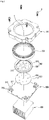
- Fig. 2 is an exploded perspective view of the lighting device shown in Fig. 1 .
- Fig. 3 is a bottom perspective view of the lighting device shown in Fig. 1 .
- Fig. 4 is an exploded perspective view of the lighting device shown in Fig. 3 .
- the lighting device may include an upper case 100, a packing structure 200, a lens structure 300, a light emitting module 400 and a lower case 500.
- the upper case 100 is coupled to the lower case 500 and forms a body of the lighting device according to the embodiment.
- the upper case 100 and the lower case 500 may be strongly coupled with each other by means of a coupling means like a coupling screw "B", etc. Since the upper case 100 and the lower case 500 may be separated from each other, it is possible to easily maintain and repair the broken or damaged parts internally disposed.
- a coupled body formed by the coupling of the upper case 100 and the lower case 500 may have a hexahedral shape.
- the shape of the coupled body is not limited to be hexahedral.
- the coupled body may have a cylindrical shape or polyhedral shape.
- a predetermined receiving space may be located between the upper case 100 and the lower case 500.
- the packing structure 200, the lens structure 300 and the light emitting module 400 are disposed in the receiving space. Specifically, the light emitting module 400 is disposed on the lower case 500.
- the lens structure 300 covering the light emitting module 400 is disposed on the lower case 500.
- the packing structure 200 covering the lens structure 300 is disposed on the lower case 500.
- the lower case 500 may be formed of a material having a heat radiating characteristic.
- the material of the lower case 500 may include a metallic material, and specifically at least one of Al, Ni, Cu, Au or Sn. Additionally, the surface of the lower case 500 may be plated with the metallic material.
- the upper case 100 may be formed of a material having a heat radiating characteristic.
- the material of the upper case 100 is not limited to this.
- the material of the upper case 100 may be a common plastic material or a synthetic resin material, each of which has no heat radiating characteristic.
- the upper case 100 or the lower case 500 transfers heat generated from the light emitting module 400 to a heat sink 600 or radiates the heat itself.
- the upper case 100 and the lower case 500 may include a plurality of fins (not shown) in order to more efficiently radiate the heat.
- the fins (not shown) increase the surface areas of the upper case 100 and the lower case 500, so that the heat generated from the light emitting module 400 can be effectively transferred or radiated.
- the upper case 100 includes a shape of a quadrangular box and an opening "H" allowing light passing through the lens structure 300 to be emitted outward.
- the upper case 100 also includes holes into which the coupling screws "B" are inserted.
- the lower case 500 may have a quadrangular flat plate shape.
- the shape of the lower case 500 is not limited to this.
- the lower case 500 may have a polygonal flat plate shape.
- the lower case 500 includes a coupler 510.
- the coupler 510 may be a protrusion projecting outward from each corner of the lower case 500.
- the couplers 510 of the lower case 500 are placed at the corners of the upper case 100 respectively. Therefore, the coupled body formed by the coupling of the lower case 500 and the upper case 100 may have actually a hexahedral shape.
- the coupler 510 has been formed at each corner of the lower case 500.
- the coupler 510 may be disposed only at some corners selected among all the corners of the lower case 500, or may be disposed on the circumference of the lower case 500 instead of the corner of the lower case 500.
- the coupler 510 includes a first coupling hole 511 into which the coupling screw "B" which has passed through the upper case 100 is inserted.
- the upper case 100 and the lower case 500 can be securely coupled to each other by passing the coupling screw "B" through the upper case 100 and inserting the coupling screw "B” into the first coupling hole 511.
- the first coupling hole 511 may have a shape projecting from the coupler 510 toward the center of the lower case 500.
- the coupler 510 includes a second coupling hole 513.
- the second coupling hole 513 is used for connecting a plurality of the lighting devices shown in Fig. 1 . This will be described in detail with reference to Fig. 5 .
- Fig. 5 is a perspective view showing that a plurality of the lighting devices shown in Fig. 1 have been connected to each other.
- a second lighting device U2 and a third lighting device U3 are disposed adjacent to each other on the basis of a first lighting device U1.
- the coupler 510 of the first lighting device U1 come in contact with the couplers of other two neighboring lighting devices.
- the second coupling hole 513 of the first lighting device U1, the second coupling hole of the second lighting device U2 and the second coupling holes of the other two lighting devices are disposed adjacent to each other.
- connection pad "P" is inserted into the four adjacent coupling holes 513.
- the four adjacent lighting devices may be coupled to each other by the connection pad "P". Therefore, the coupled four lighting devices can be used as one lighting device.
- the connection pad "P" will be described with reference to Fig. 6 .
- Fig. 6 is a perspective view of the connection pad "P" shown in Fig. 5 .
- connection pad "P" includes a plate 520 and four pins 525.
- the four pins 525 project outward from the bottom surface of the plate 520 and are inserted into the four coupling holes 513 shown in Fig. 4 .
- the top surface of the plate 520 may be disposed on the same plane with the outer surface of the upper case of the first lighting device U1 shown in Fig. 5 .
- the lighting device according to the embodiment has an advantage that it can be connected to other lighting devices which are the same as the lighting device itself. Therefore, when one lighting device shown in Fig. 1 is not able to provide desired brightness, a user has an advantage of obtaining desired brightness by connecting a plurality of the lighting devices shown in Fig. 1 .
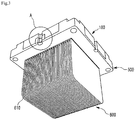
- the bottom surface of the lower case 500 includes a seating portion 530 in which the heat sink 600 is disposed.
- the seating portion 530 may be a recess which is formed by digging a portion of the bottom surface of the lower case 500 to a predetermined depth. A portion of the heat sink 600 is disposed in the recess 530. Specifically, a portion of the heat sink 600 is inserted into the recess 530.
- the seating portion 530 is not limited to the recess. This will be described with reference to Fig. 7 .
- Fig. 7 is an exploded perspective view for describing a modified example of the lower case of the lighting device shown in Fig. 4 .
- a seating portion 530' may be a projection projecting outward from the bottom surface of the lower case 500.
- the heat sink 600 may have a recess (not shown) into which the projection 530' is inserted.
- the seating portion 530 may be disposed in the bottom surface of the lower case 500, particularly, under the light emitting module 400. Specifically, the seating portion 530 is disposed at the central portion of the bottom surface of the lower case 500. The light emitting module 400 is disposed at the central portion of the top surface of the lower case 500. Since the light emitting module 400 generates the largest amount of heat, the seating portion 530 is disposed just under the light emitting module 400 in the bottom surface of the lower case 500.
- the heat sink 600 is coupled to the seating portion 530 of the lower case 500.
- the heat sink 600 may be coupled to the seating portion 530 of the lower case 500 without a separate coupling means.
- the heat sink 600 may be coupled to the lower case 500 by inserting a portion of the upper portion of the heat sink 600 into the recess 530 of the lower case 500. Additionally, the heat sink 600 may be easily separated from the lower case 500.
- the recess 530 of the lower case 500 allows the heat sink 600 to be easily attached or removed without a separate coupling means.
- the lighting device according to the embodiment does not necessarily require the heat sink 600 which occupies the most weight and thickness of a conventional lighting device. Therefore, the lighting device according to the embodiment can be smaller and lighter. Also, it is possible to reduce the cost of the heat sink 600 in the total manufacturing cost of the lighting device.
- the lighting device according to the embodiment is able to semi-permanently use the one heat sink 600.
- the heat sink 600 may have a plurality of heat radiating fins 610.
- the plurality of the heat radiating fins 610 increase the surface area of the heat sink 600 and improve a heat radiation efficiency.
- the light emitting module 400 is disposed in the lower case 500 and may include a substrate 410 and a plurality of light emitting devices 430 disposed on the substrate 410.
- the substrate 410 may have, as shown in the drawings, a disc shape. However, the shape of the substrate 410 is not limited to this.
- the substrate 410 may be formed by printing a circuit on an insulator and may include an aluminum substrate, a ceramic substrate, a metal core PCB or a common PCB.
- the substrate 410 is disposed on the top surface of the lower case 500.
- the plurality of the light emitting devices 430 are arranged on one side of the substrate 410.
- the one side of the substrate 410 may have a color capable of efficiently reflecting light, for example, white color.
- the other side of the substrate 410 comes in contact with the top surface of the lower case 500.
- the substrate 410 is electrically connected to a cable “C” shown in Fig. 8 .
- the substrate 410 is supplied with an electric power through the cable "C".
- the substrate 410 may include a DC converter or a protective device.
- the DC converter converts AC to DC and supplies the DC.
- the protective device protects the lighting device from ESD, a Surge phenomenon or the like.
- a heat radiating plate may be disposed on the bottom surface of the substrate 410.
- the heat radiating plate may efficiently transfer the heat generated from the light emitting module 400 to the lower case 500.
- the heat radiating plate may be formed of a material having thermal conductivity.
- the heat radiating plate may be a thermal conduction silicon pad or a thermal conductive tape.
- the plurality of the light emitting devices 430 are disposed on the substrate 410.
- the plurality of the light emitting devices 430 may be disposed on the substrate 410 in the form of an array.
- the shapes and the number of the plurality of the light emitting devices 430 may be variously changed according to needs.
- the light emitting device 430 may be a light emitting diode (LED). At least one of a red LED, a blue LED, a green LED or a white LED may be selectively used as the light emitting device 430.
- LED light emitting diode
- the lens structure 300 may include a lens unit 310 and an outer frame 330.
- the lens structure 330 receives the light emitting module 400.
- the cylindrical outer frame 330 surrounds the side of the substrate 410, and the lens unit 310 is disposed on one side of the substrate 410. As a result, the light emitting module 400 is received in the lens structure 300.
- the lens unit 310 includes at least one dorm-shaped lens 315.
- the dorm-shaped lens 315 may be changed in various forms if necessary, for example, a hemispherical shape, a concave shape, a convex shape or the like.
- the bottom surface of the lens 315 that is to say, a light incident surface may have an irregular shape or a prism shape in order to improve efficiency and obtain a desired light distribution.
- the lens 315 controls light emitted from the light emitting module 400.
- the control of the light means diffusion or collection of the light from the light emitting module 400.
- the lens 315 is able to diffuse the light from the light emitting device 430.
- the lens 315 is also able to collect the light from the light emitting device 430 instead of diffusing.
- the lens 315 may one-to-one correspond to the light emitting device 430 of the light emitting module 400. That is, the number of the lenses 315 corresponds to the number of the light emitting devices 430. For example, as shown in Fig. 2 , when 8 light emitting devices 430 are disposed on the substrate 410, 8 lenses 315 one-to-one correspond to the 8 light emitting devices 430.
- the lens 315 may one-to-many correspond to the light emitting device 430 of the light emitting module 400. In other words, one lens 315 may correspond to two or more light emitting devices 430.
- the lens 315 may include a fluorescent material (not shown).
- the fluorescent material may be a yellow fluorescent material, a green fluorescent material or a red fluorescent material.
- the lens 315 may include at least one of the yellow, green and red fluorescent materials. Due to the fluorescent material included in the lens 315, a color rendering index (CRI) of light emitted from the lighting device according to the embodiment can be improved.
- CRI color rendering index
- the outer frame 330 is disposed on the top surface of the lower case 500 in such a manner as to cover the light emitting module 400.
- the outer frame 330 is disposed on the top surface of the lower case 500, so that the lens unit 310 is spaced apart from the light emitting device 430 of the light emitting module 400 at a certain interval. Therefore, the outer frame 330 forms a predetermined space between the lens unit 310 and the light emitting device 430.
- a beam angle of light emitted from the light emitting device 430 is approximately 120°. In order to obtain a designer's desired light distribution by using the beam angle, a certain interval "G1" is required between the light emitting device 430 and the lens unit 310.
- the outer frame 330 is received in the packing structure 200. Specifically, the outer frame 330 is surrounded by the packing structure 200. Therefore, the packing structure 200 protects the outer frame 330 from external impact.
- the lens structure 300 may be injection-molded by using a light-transmitting material.
- the material of the lens structure 300 may be implemented by glass or a plastic material such as poly methyl methacrylate (PMMA) or polycarbonate (PC) or the like.
- the packing structure 200 is disposed on the lower case 500 and receives the lens structure 300. Specifically, the packing structure 200 is disposed on the top surface of the lower case 500 in such a manner as to cover the lens structure 300.
- the packing structure 200 is disposed between the upper case 100 and the lower case 500, which prevents water and impurity from penetrating into the lens structure 300 and the light emitting module 400.
- the packing structure 200 is able to protect the lens structure 300 and the light emitting module 400 from external impact.
- the packing structure 200 may have a circular ring shape to surround the outer frame 330 of the lens structure 300.
- the packing structure 200 may be formed of a material which easily absorbs shock without allowing water to penetrate thereinto.
- the packing structure 200 may be formed of a waterproof rubber, a waterproof silicon material or the like.
- the packing structure 200 is formed of an elastic material such as the rubber or the silicon material, the packing structure 200 is pressed between the upper case 100 and the lower case 500.
- the lighting device according to the embodiment shown in Figs. 1 to 4 is able to improve the flexibility of a cable supplying electric power to the lighting device.
- this will be described with reference to Fig. 8 .
- Fig. 8 is a perspective view for describing the flexibility of the cable connected to the lighting device shown in Fig. 1 .
- a part “A” is equipped with an electric wire “C” supplying electric power to the lighting device according to the embodiment.
- the electric wire “C” is electrically connected to the light emitting module 400 shown in Fig. 2 and supplies electric power to the light emitting module 400.
- the electric wire “C” may be a general cable “C”.
- the electric wire “C” will be described by assuming that the electric wire “C” is a cable “C”.
- the cable “C” can freely move to the upper case 100 or the lower case 500.
- a structure for improving the flexibility of the cable “C” will be described in detail with reference to Fig. 4 .
- the upper case 100 includes an insertion recess 110 and an upper seating recess 130.
- the packing structure 200 includes a projection 210 and a cover recess 230.
- the lower case 500 includes a lower seating recess 550.
- the insertion recess 110 of the upper case 100 receives the projection 210 of the packing structure 200.
- the cable “C” is seated in the upper seating recess 130 of the upper case 100.
- the upper seating recess 130 receives the cable "C”.
- the projection 210 of the packing structure 200 has a shape projecting outward from one side of the packing structure 200.
- the projection 210 is received in the insertion recess 110 of the upper case 100. Here, a portion of the projection 210 is exposed outward.
- the projection 210 includes the cover recess 230.
- a portion of the cable “C” is disposed in the cover recess 230.
- the cover recess 230 protects the cable “C” and prevents the movement of the cable “C” in the lighting device.
- the cable "C” disposed in the cover recess 230 is pressed between the packing structure 200 and the top surface of the lower case 500. Therefore, water or impurity which is introduced along the surface of the cable "C" is blocked.
- the cable “C” is seated in the lower seating recess 550 of the lower case 500.
- the lower seating recess 550 receives the cable "C”.
- the lighting device according to the embodiment has an advantage of improving the flexibility of the cable "C”. Also, as shown in Fig. 5 , the plurality of the lighting devices according to the embodiment can be connected with each other regardless of the disposition of the cable "C”.
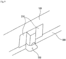
- Fig. 9 shows a modified example of a part "A" shown in Fig. 3 .
- FIG. 9 shows that the upper case 100 does not include the upper seating recess 130 shown in Fig. 4 .
- the cable "C" is disposed in the lower seating recess 550 of the lower case 500.
- the lower case 500 may not include the lower seating recess 550, and the upper case 100 may include the upper seating recess 130 shown in Fig. 4 .
- the cable "C" is disposed in the upper seating recess 130 of the upper case 100.
- any reference in this specification to "one embodiment,” “an embodiment,” “example embodiment,” etc. means that a particular feature, structure, or characteristic described in connection with the embodiment is included in at least one embodiment of the invention.
- the appearances of such phrases in various places in the specification are not necessarily all referring to the same embodiment.
Description
- Embodiments may relate to a lighting device.
- A light emitting diode (LED) is an energy device for converting electric energy into light energy. Compared with an electric bulb, the LED has higher conversion efficiency, lower power consumption and a longer life span. As there advantages are widely known, more and more attentions are now paid to a lighting apparatus using the LED.
- The lighting apparatus using the LED are generally classified into a direct lighting apparatus and an indirect lighting apparatus. The direct lighting apparatus emits light emitted from the LED without changing the path of the light. The indirect lighting apparatus emits light emitted from the LED by changing the path of the light through reflecting means and so on. Compared with the direct lighting apparatus, the indirect lighting apparatus mitigates to some degree the intensified light emitted from the LED and protects the eyes of users.
- Some LED lighting devices are disclosed in
KR100981329B1 EP1108612A2 ,KR20044548Y1 US2009/0201683A1 andUS2010/0061108A1 . - One embodiment is a lighting device. The lighting device includes: a light emitting module including a substrate and a light emitting device disposed on the substrate; and a case receiving the light emitting module therewithin and including an upper case disposed on the substrate and a lower case in which the substrate is disposed. The lower case includes a seating portion which is coupled to a heat sink. The seating portion is either a projection projecting outward from the outer surface of the lower case or a recess which is formed by digging inward the outer surface of the lower case.
- Another embodiment is a lighting device. The lighting device includes: a lower case including one side; a light emitting module which is disposed on the one side and includes a light emitting device; a lens structure which is disposed on the one side of the lower case in such a manner as to cover the light emitting module and controls light emitted from the light emitted module; a packing structure which is disposed on the one side of the lower case in such a manner as to cover the lens structure; and an upper case which covers the packing structure and is coupled to the lower case.
- Further another embodiment is a lighting device. The lighting device includes: a first case which includes a first coupler; a first light emitting module disposed in the first case; a second case which is disposed adjacent to the first case and includes a second coupler; a second light emitting module disposed in the second case; and a connection pad which connects the first case with the second case. The first coupler includes a first coupling hole, wherein the second coupler includes a second coupling hole. The connection pad includes pins which are inserted into the first coupling hole and the second coupling hole.
- Arrangements and embodiments may be described in detail with reference to the following drawings in which like reference numerals refer to like elements and wherein:
-
Fig. 1 is a perspective view of a lighting device according to an embodiment; -
Fig. 2 is an exploded perspective view of the lighting device shown inFig. 1 ; -
Fig. 3 is a bottom perspective view of the lighting device shown inFig. 1 ; -
Fig. 4 is an exploded perspective view of the lighting device shown inFig. 3 ; -
Fig. 5 is a perspective view showing that a plurality of the lighting devices shown inFig. 1 have been connected to each other; -
Fig. 6 is a perspective view of a connection pad shown inFig. 5 ; -
Fig. 7 is an exploded perspective view for describing a modified example of a lower case of the lighting device shown inFig. 4 ; -
Fig. 8 is a perspective view for describing the flexibility of a cable connected to the lighting device shown inFig. 1 ; and -
Fig. 9 shows a modified example of a part "A" shown inFig. 3 . - A thickness or a size of each layer may be magnified, omitted or schematically shown for the purpose of convenience and clearness of description. The size of each component may not necessarily mean its actual size.
- It should be understood that when an element is referred to as being 'on' or "under" another element, it may be directly on/under the element, and/or one or more intervening elements may also be present. When an element is referred to as being 'on' or 'under', 'under the element' as well as 'on the element' may be included based on the element.
- An embodiment may be described in detail with reference to the accompanying drawings.
-
Fig. 1 is a perspective view of a lighting device according to an embodiment.Fig. 2 is an exploded perspective view of the lighting device shown inFig. 1 .Fig. 3 is a bottom perspective view of the lighting device shown inFig. 1 .Fig. 4 is an exploded perspective view of the lighting device shown inFig. 3 . - Referring to
Figs. 1 to 4 , the lighting device according to the embodiment may include anupper case 100, apacking structure 200, alens structure 300, alight emitting module 400 and alower case 500. - The
upper case 100 is coupled to thelower case 500 and forms a body of the lighting device according to the embodiment. Theupper case 100 and thelower case 500 may be strongly coupled with each other by means of a coupling means like a coupling screw "B", etc. Since theupper case 100 and thelower case 500 may be separated from each other, it is possible to easily maintain and repair the broken or damaged parts internally disposed. - A coupled body formed by the coupling of the
upper case 100 and thelower case 500 may have a hexahedral shape. Here, the shape of the coupled body is not limited to be hexahedral. For example, the coupled body may have a cylindrical shape or polyhedral shape. - A predetermined receiving space may be located between the
upper case 100 and thelower case 500. Thepacking structure 200, thelens structure 300 and thelight emitting module 400 are disposed in the receiving space. Specifically, thelight emitting module 400 is disposed on thelower case 500. Thelens structure 300 covering thelight emitting module 400 is disposed on thelower case 500. Thepacking structure 200 covering thelens structure 300 is disposed on thelower case 500. - The
lower case 500 may be formed of a material having a heat radiating characteristic. For example, the material of thelower case 500 may include a metallic material, and specifically at least one of Al, Ni, Cu, Au or Sn. Additionally, the surface of thelower case 500 may be plated with the metallic material. - Like the
lower case 500, theupper case 100 may be formed of a material having a heat radiating characteristic. However, the material of theupper case 100 is not limited to this. Specifically, the material of theupper case 100 may be a common plastic material or a synthetic resin material, each of which has no heat radiating characteristic. - The
upper case 100 or thelower case 500 transfers heat generated from thelight emitting module 400 to aheat sink 600 or radiates the heat itself. Here, theupper case 100 and thelower case 500 may include a plurality of fins (not shown) in order to more efficiently radiate the heat. The fins (not shown) increase the surface areas of theupper case 100 and thelower case 500, so that the heat generated from thelight emitting module 400 can be effectively transferred or radiated. - The
upper case 100 includes a shape of a quadrangular box and an opening "H" allowing light passing through thelens structure 300 to be emitted outward. Theupper case 100 also includes holes into which the coupling screws "B" are inserted. - The
lower case 500 may have a quadrangular flat plate shape. However, the shape of thelower case 500 is not limited to this. For example, thelower case 500 may have a polygonal flat plate shape. - The
lower case 500 includes acoupler 510. Thecoupler 510 may be a protrusion projecting outward from each corner of thelower case 500. - Through the coupling of the
lower case 500 and theupper case 100, thecouplers 510 of thelower case 500 are placed at the corners of theupper case 100 respectively. Therefore, the coupled body formed by the coupling of thelower case 500 and theupper case 100 may have actually a hexahedral shape. - In
Figs. 1 to 4 , it is shown that thecoupler 510 has been formed at each corner of thelower case 500. However, there is no limit to where thecoupler 510 is formed. Thecoupler 510 may be disposed only at some corners selected among all the corners of thelower case 500, or may be disposed on the circumference of thelower case 500 instead of the corner of thelower case 500. - The
coupler 510 includes afirst coupling hole 511 into which the coupling screw "B" which has passed through theupper case 100 is inserted. Theupper case 100 and thelower case 500 can be securely coupled to each other by passing the coupling screw "B" through theupper case 100 and inserting the coupling screw "B" into thefirst coupling hole 511. Thefirst coupling hole 511 may have a shape projecting from thecoupler 510 toward the center of thelower case 500. - The
coupler 510 includes asecond coupling hole 513. Thesecond coupling hole 513 is used for connecting a plurality of the lighting devices shown inFig. 1 . This will be described in detail with reference toFig. 5 . -
Fig. 5 is a perspective view showing that a plurality of the lighting devices shown inFig. 1 have been connected to each other. - A second lighting device U2 and a third lighting device U3 are disposed adjacent to each other on the basis of a first lighting device U1.
- The
coupler 510 of the first lighting device U1 come in contact with the couplers of other two neighboring lighting devices. Thesecond coupling hole 513 of the first lighting device U1, the second coupling hole of the second lighting device U2 and the second coupling holes of the other two lighting devices are disposed adjacent to each other. - A connection pad "P" is inserted into the four adjacent coupling holes 513. The four adjacent lighting devices may be coupled to each other by the connection pad "P". Therefore, the coupled four lighting devices can be used as one lighting device. The connection pad "P" will be described with reference to
Fig. 6 . -
Fig. 6 is a perspective view of the connection pad "P" shown inFig. 5 . - Referring to
Fig. 6 , the connection pad "P" includes aplate 520 and fourpins 525. The fourpins 525 project outward from the bottom surface of theplate 520 and are inserted into the fourcoupling holes 513 shown inFig. 4 . - The top surface of the
plate 520 may be disposed on the same plane with the outer surface of the upper case of the first lighting device U1 shown inFig. 5 . - As shown in
Figs. 1 to 6 , the lighting device according to the embodiment has an advantage that it can be connected to other lighting devices which are the same as the lighting device itself. Therefore, when one lighting device shown inFig. 1 is not able to provide desired brightness, a user has an advantage of obtaining desired brightness by connecting a plurality of the lighting devices shown inFig. 1 . - Referring back to
Figs. 1 to 4 , the bottom surface of thelower case 500 includes aseating portion 530 in which theheat sink 600 is disposed. - The
seating portion 530 may be a recess which is formed by digging a portion of the bottom surface of thelower case 500 to a predetermined depth. A portion of theheat sink 600 is disposed in therecess 530. Specifically, a portion of theheat sink 600 is inserted into therecess 530. Here, theseating portion 530 is not limited to the recess. This will be described with reference toFig. 7 . -
Fig. 7 is an exploded perspective view for describing a modified example of the lower case of the lighting device shown inFig. 4 . - Referring to
Fig. 7 , a seating portion 530' may be a projection projecting outward from the bottom surface of thelower case 500. When the seating portion 530' is a projection, theheat sink 600 may have a recess (not shown) into which the projection 530' is inserted. - Referring back to
Figs. 1 to 4 , theseating portion 530 may be disposed in the bottom surface of thelower case 500, particularly, under thelight emitting module 400. Specifically, theseating portion 530 is disposed at the central portion of the bottom surface of thelower case 500. Thelight emitting module 400 is disposed at the central portion of the top surface of thelower case 500. Since thelight emitting module 400 generates the largest amount of heat, theseating portion 530 is disposed just under thelight emitting module 400 in the bottom surface of thelower case 500. - The
heat sink 600 is coupled to theseating portion 530 of thelower case 500. Here, theheat sink 600 may be coupled to theseating portion 530 of thelower case 500 without a separate coupling means. Specifically, theheat sink 600 may be coupled to thelower case 500 by inserting a portion of the upper portion of theheat sink 600 into therecess 530 of thelower case 500. Additionally, theheat sink 600 may be easily separated from thelower case 500. In the lighting device according to the embodiment, therecess 530 of thelower case 500 allows theheat sink 600 to be easily attached or removed without a separate coupling means. - The lighting device according to the embodiment does not necessarily require the
heat sink 600 which occupies the most weight and thickness of a conventional lighting device. Therefore, the lighting device according to the embodiment can be smaller and lighter. Also, it is possible to reduce the cost of theheat sink 600 in the total manufacturing cost of the lighting device. - Further, the lighting device according to the embodiment is able to semi-permanently use the one
heat sink 600. - The
heat sink 600 may have a plurality ofheat radiating fins 610. The plurality of theheat radiating fins 610 increase the surface area of theheat sink 600 and improve a heat radiation efficiency. - The
light emitting module 400 is disposed in thelower case 500 and may include asubstrate 410 and a plurality of light emittingdevices 430 disposed on thesubstrate 410. - The
substrate 410 may have, as shown in the drawings, a disc shape. However, the shape of thesubstrate 410 is not limited to this. Thesubstrate 410 may be formed by printing a circuit on an insulator and may include an aluminum substrate, a ceramic substrate, a metal core PCB or a common PCB. - The
substrate 410 is disposed on the top surface of thelower case 500. - The plurality of the
light emitting devices 430 are arranged on one side of thesubstrate 410. The one side of thesubstrate 410 may have a color capable of efficiently reflecting light, for example, white color. The other side of thesubstrate 410 comes in contact with the top surface of thelower case 500. - The
substrate 410 is electrically connected to a cable "C" shown inFig. 8 . Thesubstrate 410 is supplied with an electric power through the cable "C". - The
substrate 410 may include a DC converter or a protective device. The DC converter converts AC to DC and supplies the DC. The protective device protects the lighting device from ESD, a Surge phenomenon or the like. - A heat radiating plate (not shown) may be disposed on the bottom surface of the
substrate 410. The heat radiating plate (not shown) may efficiently transfer the heat generated from thelight emitting module 400 to thelower case 500. The heat radiating plate (not shown) may be formed of a material having thermal conductivity. For example, the heat radiating plate may be a thermal conduction silicon pad or a thermal conductive tape. - The plurality of the
light emitting devices 430 are disposed on thesubstrate 410. Here, the plurality of thelight emitting devices 430 may be disposed on thesubstrate 410 in the form of an array. The shapes and the number of the plurality of thelight emitting devices 430 may be variously changed according to needs. - The
light emitting device 430 may be a light emitting diode (LED). At least one of a red LED, a blue LED, a green LED or a white LED may be selectively used as thelight emitting device 430. - The
lens structure 300 may include alens unit 310 and anouter frame 330. Thelens structure 330 receives thelight emitting module 400. Specifically, the cylindricalouter frame 330 surrounds the side of thesubstrate 410, and thelens unit 310 is disposed on one side of thesubstrate 410. As a result, thelight emitting module 400 is received in thelens structure 300. - The
lens unit 310 includes at least one dorm-shapedlens 315. Here, the dorm-shapedlens 315 may be changed in various forms if necessary, for example, a hemispherical shape, a concave shape, a convex shape or the like. - When the
lens 315 of thelens unit 310 has a hemispherical shape, although not specially shown in the drawings, the bottom surface of thelens 315, that is to say, a light incident surface may have an irregular shape or a prism shape in order to improve efficiency and obtain a desired light distribution. - The
lens 315 controls light emitted from thelight emitting module 400. Here, the control of the light means diffusion or collection of the light from thelight emitting module 400. Specifically, when thelight emitting device 430 of thelight emitting module 400 is a light emitting diode, thelens 315 is able to diffuse the light from thelight emitting device 430. Additionally, thelens 315 is also able to collect the light from thelight emitting device 430 instead of diffusing. - The
lens 315 may one-to-one correspond to thelight emitting device 430 of thelight emitting module 400. That is, the number of thelenses 315 corresponds to the number of thelight emitting devices 430. For example, as shown inFig. 2 , when 8light emitting devices 430 are disposed on thesubstrate 410, 8lenses 315 one-to-one correspond to the 8light emitting devices 430. Here, thelens 315 may one-to-many correspond to thelight emitting device 430 of thelight emitting module 400. In other words, onelens 315 may correspond to two or more light emittingdevices 430. - The
lens 315 may include a fluorescent material (not shown). The fluorescent material may be a yellow fluorescent material, a green fluorescent material or a red fluorescent material. When thelight emitting device 430 of thelight emitting module 400 is a blue light emitting diode, thelens 315 may include at least one of the yellow, green and red fluorescent materials. Due to the fluorescent material included in thelens 315, a color rendering index (CRI) of light emitted from the lighting device according to the embodiment can be improved. - The
outer frame 330 is disposed on the top surface of thelower case 500 in such a manner as to cover thelight emitting module 400. - The
outer frame 330 is disposed on the top surface of thelower case 500, so that thelens unit 310 is spaced apart from thelight emitting device 430 of thelight emitting module 400 at a certain interval. Therefore, theouter frame 330 forms a predetermined space between thelens unit 310 and thelight emitting device 430. When thelight emitting device 430 of thelight emitting module 400 is a light emitting diode, a beam angle of light emitted from thelight emitting device 430 is approximately 120°. In order to obtain a designer's desired light distribution by using the beam angle, a certain interval "G1" is required between the light emittingdevice 430 and thelens unit 310. - The
outer frame 330 is received in thepacking structure 200. Specifically, theouter frame 330 is surrounded by the packingstructure 200. Therefore, the packingstructure 200 protects theouter frame 330 from external impact. - The
lens structure 300 may be injection-molded by using a light-transmitting material. The material of thelens structure 300 may be implemented by glass or a plastic material such as poly methyl methacrylate (PMMA) or polycarbonate (PC) or the like. - The packing
structure 200 is disposed on thelower case 500 and receives thelens structure 300. Specifically, the packingstructure 200 is disposed on the top surface of thelower case 500 in such a manner as to cover thelens structure 300. - The packing
structure 200 is disposed between theupper case 100 and thelower case 500, which prevents water and impurity from penetrating into thelens structure 300 and thelight emitting module 400. The packingstructure 200 is able to protect thelens structure 300 and thelight emitting module 400 from external impact. - The packing
structure 200 may have a circular ring shape to surround theouter frame 330 of thelens structure 300. - The packing
structure 200 may be formed of a material which easily absorbs shock without allowing water to penetrate thereinto. For example, the packingstructure 200 may be formed of a waterproof rubber, a waterproof silicon material or the like. Here, when thepacking structure 200 is formed of an elastic material such as the rubber or the silicon material, the packingstructure 200 is pressed between theupper case 100 and thelower case 500. - The lighting device according to the embodiment shown in
Figs. 1 to 4 is able to improve the flexibility of a cable supplying electric power to the lighting device. Hereafter, this will be described with reference toFig. 8 . -
Fig. 8 is a perspective view for describing the flexibility of the cable connected to the lighting device shown inFig. 1 . - Referring to
Figs. 3 and8 , a part "A" is equipped with an electric wire "C" supplying electric power to the lighting device according to the embodiment. The electric wire "C" is electrically connected to thelight emitting module 400 shown inFig. 2 and supplies electric power to thelight emitting module 400. Here, the electric wire "C" may be a general cable "C". Hereafter, the electric wire "C" will be described by assuming that the electric wire "C" is a cable "C". - The cable "C" can freely move to the
upper case 100 or thelower case 500. A structure for improving the flexibility of the cable "C" will be described in detail with reference toFig. 4 . - Referring to
Fig. 4 , theupper case 100 includes aninsertion recess 110 and anupper seating recess 130. The packingstructure 200 includes aprojection 210 and acover recess 230. Thelower case 500 includes alower seating recess 550. - In the coupling of the
packing structure 200 and theupper case 100, theinsertion recess 110 of theupper case 100 receives theprojection 210 of thepacking structure 200. - The cable "C" is seated in the
upper seating recess 130 of theupper case 100. When the cable "C" is expected to be disposed toward theupper case 100, theupper seating recess 130 receives the cable "C". - The
projection 210 of thepacking structure 200 has a shape projecting outward from one side of thepacking structure 200. Theprojection 210 is received in theinsertion recess 110 of theupper case 100. Here, a portion of theprojection 210 is exposed outward. - The
projection 210 includes thecover recess 230. A portion of the cable "C" is disposed in thecover recess 230. Thecover recess 230 protects the cable "C" and prevents the movement of the cable "C" in the lighting device. - The cable "C" disposed in the
cover recess 230 is pressed between the packingstructure 200 and the top surface of thelower case 500. Therefore, water or impurity which is introduced along the surface of the cable "C" is blocked. - The cable "C" is seated in the
lower seating recess 550 of thelower case 500. When the cable "C" is expected to be disposed toward thelower case 500, thelower seating recess 550 receives the cable "C". - The
insertion recess 110 and theupper seating recess 130 of theupper case 100, theprojection 210 and thecover recess 230 of thepacking structure 200, and thelower seating recess 550 of thelower case 500 allow the cable "C" electrically connected to thelight emitting module 400 to freely move to theupper case 100 or thelower case 500 and to be disposed in theupper case 100 or thelower case 500. Therefore, the lighting device according to the embodiment has an advantage of improving the flexibility of the cable "C". Also, as shown inFig. 5 , the plurality of the lighting devices according to the embodiment can be connected with each other regardless of the disposition of the cable "C". -
Fig. 9 shows a modified example of a part "A" shown inFig. 3 . - A modified example shown in
Fig. 9 shows that theupper case 100 does not include theupper seating recess 130 shown inFig. 4 . In this case, the cable "C" is disposed in thelower seating recess 550 of thelower case 500. - Unlike the modified example shown in
Fig. 9 , thelower case 500 may not include thelower seating recess 550, and theupper case 100 may include theupper seating recess 130 shown inFig. 4 . In this case, the cable "C" is disposed in theupper seating recess 130 of theupper case 100. - Any reference in this specification to "one embodiment," "an embodiment," "example embodiment," etc., means that a particular feature, structure, or characteristic described in connection with the embodiment is included in at least one embodiment of the invention. The appearances of such phrases in various places in the specification are not necessarily all referring to the same embodiment. Further, when a particular feature, structure, or characteristic is described in connection with any embodiment, it is submitted that it is within the purview of one skilled in the art to affect such feature, structure, or characteristic in connection with other ones of the embodiments.
- Although embodiments have been described with reference to a number of illustrative embodiments thereof, it should be understood that numerous other modifications and embodiments can be devised by those skilled in the art that will fall within the scope of this disclosure. More particularly, various variations and modifications are possible in the component parts and/or arrangements of the subject combination arrangement within the scope of the disclosure, the drawings and the appended claims. In addition to variations and modifications in the component parts and/or arrangements, alternative uses will also be apparent to those skilled in the art.
Claims (8)
- A lighting device comprising:a light emitting module (400) which includes a substrate (410) and a light emitting device (430) disposed on the substrate;a case (100, 500) which receives the light emitting module (400) therewithin and includes an upper case (100) disposed on the substrate (410) and a lower case (500) in which the substrate (410) is disposed;a heat sink (600) coupled to the lower case (500);a lens structure (300) receiving the light emitting module (400);anda packing structure (200) disposed on the lower case (500) and receiving the lens structure (300),wherein the lower case (500) includes a bottom surface and an top surface,characterized in that the lower case (500) includes a seating portion (530) which is disposed on the bottom surface of the lower case (500),,the seating portion (530) is a recess (530) which is formed by digging a portion of the bottom surface of the lower case (500) to a predetermined depth, anda portion of the heat sink (600) is inserted into the seating portion (530),the packing structure (200) is formed of an elastic material, andthe packing structure (200) is pressed between the upper case (100) and the lower case (500).
- The lighting device of claim 1, wherein the seating portion (530, 530') is disposed under the light emitting module (400).
- The lighting device of claim 1 or 2, further comprising a lens structure (300) which is disposed on the lower case (500) and receives the light emitting module (400); and a packing structure (200) which is disposed on the lower case (500) and receives the lens structure (300), wherein the lens structure (300) comprises an outer frame (330) which surrounds the substrate (410) of the light emitting module (400) and comprises a lens unit (310) which is disposed on the substrate (410) and includes lenses (315) corresponding to the light emitting devices (430).
- The lighting device of claim 3, wherein the outer frame (330) of the lens structure (300) causes the lens (315) and the light emitting device (430) to be spaced from each other at a predetermined interval.
- The lighting device of claim 3 or 4, wherein the lens (315) comprises at least one of yellow, green and/or red fluorescent materials.
- The lighting device of any one claim of claims 3 to 5, wherein further comprising a cable (C) which is electrically connected to the substrate (410) of the light emitting module (400), wherein the packing structure (200) comprises a cover recess (230) in which the cable (C) is disposed and a projection (210) which includes the cover recess (230) and projects outward, wherein the upper case (100) comprises an insertion recess (110) into which the projection (210) of the packing structure (200) is inserted, and wherein the lower case (500) comprises a lower seating recess (550) into which the cable (C) is inserted.
- The lighting device of claim 6, wherein the upper case (100) comprises an upper seating recess (130) into which the cable is inserted.
- The lighting device of claim 6 or 7, wherein the lower case (500) as well as the packing structure (200) presses the cable (C).
Applications Claiming Priority (3)
| Application Number | Priority Date | Filing Date | Title |
|---|---|---|---|
| KR1020110015986A KR101800376B1 (en) | 2011-02-23 | 2011-02-23 | Lighting device |
| KR1020110015987A KR101879216B1 (en) | 2011-02-23 | 2011-02-23 | Lighting device |
| KR1020110019266A KR101823135B1 (en) | 2011-03-04 | 2011-03-04 | Lighting device |
Publications (3)
| Publication Number | Publication Date |
|---|---|
| EP2492586A2 EP2492586A2 (en) | 2012-08-29 |
| EP2492586A3 EP2492586A3 (en) | 2014-05-07 |
| EP2492586B1 true EP2492586B1 (en) | 2019-04-10 |
Family
ID=45554467
Family Applications (1)
| Application Number | Title | Priority Date | Filing Date |
|---|---|---|---|
| EP12151136.4A Active EP2492586B1 (en) | 2011-02-23 | 2012-01-13 | Lighting device |
Country Status (3)
| Country | Link |
|---|---|
| US (1) | US8556461B2 (en) |
| EP (1) | EP2492586B1 (en) |
| CN (1) | CN102650384B (en) |
Families Citing this family (14)
| Publication number | Priority date | Publication date | Assignee | Title |
|---|---|---|---|---|
| CN104235640B (en) * | 2013-06-09 | 2016-04-06 | 四川新力光源股份有限公司 | Integrated LED photo engine |
| CN103423647B (en) * | 2013-08-26 | 2015-08-12 | 湖南吉光科技有限责任公司 | LED module and adopt the light fixture of this LED module |
| CN103557448B (en) * | 2013-10-12 | 2016-02-03 | 王丽娜 | Led lamp |
| CN103759234B (en) * | 2014-01-02 | 2015-12-23 | 浙江通明电器有限公司 | The processing method of a kind of LED lamp heat sink, this radiator and LED |
| US9506609B1 (en) | 2014-03-19 | 2016-11-29 | System Lighting Solutions, Llc | Light system and method of installing |
| US10375791B2 (en) | 2014-03-19 | 2019-08-06 | System Lighting Solutions, Llc | Lighting system and method of installing |
| CN103899958B (en) * | 2014-03-25 | 2016-04-06 | 深圳宁大光电科技有限公司 | A kind of pixel type LED light device |
| US20160146406A1 (en) * | 2014-11-24 | 2016-05-26 | Neptun Light, Inc. | LED Tennis Court Fixture |
| KR101722682B1 (en) * | 2015-01-02 | 2017-04-04 | 주식회사 케이엠더블유 | LED lighting device that directly connected to the power supply |
| USD835305S1 (en) | 2016-06-28 | 2018-12-04 | System Lighting Solutions, Llc | Light and track assembly |
| USD811648S1 (en) * | 2016-06-28 | 2018-02-27 | System Lighting Solutions, Llc | Lens for lights |
| USD810354S1 (en) * | 2016-06-28 | 2018-02-13 | Tye T. Farnsworth | Light assembly |
| USD823496S1 (en) | 2016-06-28 | 2018-07-17 | System Lighting Solutions, Llc | Light and track assembly |
| USD816889S1 (en) | 2016-06-28 | 2018-05-01 | System Lighting Solutions, Llc | Track assembly for lights |
Family Cites Families (9)
| Publication number | Priority date | Publication date | Assignee | Title |
|---|---|---|---|---|
| US6161910A (en) * | 1999-12-14 | 2000-12-19 | Aerospace Lighting Corporation | LED reading light |
| US8182116B2 (en) * | 2007-10-10 | 2012-05-22 | Cordelia Lighting, Inc. | Lighting fixture with recessed baffle trim unit |
| US20090201683A1 (en) * | 2008-02-08 | 2009-08-13 | Tang Shih Chuan | Light-emitting diode (led) lamp with a cooling seat |
| CN201382312Y (en) * | 2009-02-26 | 2010-01-13 | 天台县海威机电有限公司 | LED lamp module with glass mirror |
| KR200445485Y1 (en) * | 2009-03-20 | 2009-08-04 | 서정호 | Led lighting lamp |
| CN201462503U (en) * | 2009-06-09 | 2010-05-12 | 陈怀中 | LED lamplight engine |
| CN101893174A (en) * | 2010-04-13 | 2010-11-24 | 苏州中泽光电科技有限公司 | Punching, light-distributing and heat-radiating integrated LED light source module |
| KR100981329B1 (en) * | 2010-06-09 | 2010-09-10 | (주)대신엘이디 | An led lamp for exterior light system |
| KR101370920B1 (en) * | 2010-06-23 | 2014-03-07 | 엘지전자 주식회사 | Lighting Device |
-
2012
- 2012-01-13 EP EP12151136.4A patent/EP2492586B1/en active Active
- 2012-02-03 US US13/365,655 patent/US8556461B2/en active Active
- 2012-02-15 CN CN201210034474.9A patent/CN102650384B/en active Active
Non-Patent Citations (1)
| Title |
|---|
| None * |
Also Published As
| Publication number | Publication date |
|---|---|
| CN102650384A (en) | 2012-08-29 |
| EP2492586A2 (en) | 2012-08-29 |
| US8556461B2 (en) | 2013-10-15 |
| CN102650384B (en) | 2016-05-25 |
| EP2492586A3 (en) | 2014-05-07 |
| US20120212930A1 (en) | 2012-08-23 |
Similar Documents
| Publication | Publication Date | Title |
|---|---|---|
| EP2492586B1 (en) | Lighting device | |
| US9970647B2 (en) | Lighting module and lighting device | |
| US8911110B2 (en) | Lighting device | |
| TWI424131B (en) | Lighting device | |
| US9303822B2 (en) | Lighting device | |
| US8267549B2 (en) | Illumination device | |
| US8304971B2 (en) | LED light bulb with a multidirectional distribution and novel heat dissipating structure | |
| US20190003660A1 (en) | Lighting module, and lighting apparatus having same | |
| US20140168995A1 (en) | Lens and led lamp having the same | |
| KR101800376B1 (en) | Lighting device | |
| KR101879216B1 (en) | Lighting device | |
| KR101610318B1 (en) | Lighting device | |
| KR20130084395A (en) | Lighting device | |
| KR101742677B1 (en) | Lighting apparatus | |
| KR101823135B1 (en) | Lighting device | |
| KR101859457B1 (en) | Lighting device | |
| KR102024703B1 (en) | Lighting device | |
| KR20130095022A (en) | Lighting device | |
| KR102014174B1 (en) | Lighting device | |
| KR101977649B1 (en) | Lighting device | |
| KR20130079672A (en) | Light device |
Legal Events
| Date | Code | Title | Description |
|---|---|---|---|
| PUAI | Public reference made under article 153(3) epc to a published international application that has entered the european phase |
Free format text: ORIGINAL CODE: 0009012 |
|
| AK | Designated contracting states |
Kind code of ref document: A2 Designated state(s): AL AT BE BG CH CY CZ DE DK EE ES FI FR GB GR HR HU IE IS IT LI LT LU LV MC MK MT NL NO PL PT RO RS SE SI SK SM TR |
|
| AX | Request for extension of the european patent |
Extension state: BA ME |
|
| RIC1 | Information provided on ipc code assigned before grant |
Ipc: F21V 15/01 20060101AFI20131210BHEP Ipc: F21K 99/00 20100101ALI20131210BHEP Ipc: F21V 29/00 20060101ALI20131210BHEP |
|
| PUAL | Search report despatched |
Free format text: ORIGINAL CODE: 0009013 |
|
| 17P | Request for examination filed |
Effective date: 20140331 |
|
| AK | Designated contracting states |
Kind code of ref document: A3 Designated state(s): AL AT BE BG CH CY CZ DE DK EE ES FI FR GB GR HR HU IE IS IT LI LT LU LV MC MK MT NL NO PL PT RO RS SE SI SK SM TR |
|
| AX | Request for extension of the european patent |
Extension state: BA ME |
|
| RIC1 | Information provided on ipc code assigned before grant |
Ipc: F21K 99/00 20100101ALI20140331BHEP Ipc: F21V 15/01 20060101AFI20140331BHEP Ipc: F21V 29/00 20060101ALI20140331BHEP |
|
| RAP1 | Party data changed (applicant data changed or rights of an application transferred) |
Owner name: LG INNOTEK CO., LTD. |
|
| RBV | Designated contracting states (corrected) |
Designated state(s): AL AT BE BG CH CY CZ DE DK EE ES FI FR GB GR HR HU IE IS IT LI LT LU LV MC MK MT NL NO PL PT RO RS SE SI SK SM TR |
|
| RAP1 | Party data changed (applicant data changed or rights of an application transferred) |
Owner name: LG INNOTEK CO., LTD. |
|
| GRAP | Despatch of communication of intention to grant a patent |
Free format text: ORIGINAL CODE: EPIDOSNIGR1 |
|
| STAA | Information on the status of an ep patent application or granted ep patent |
Free format text: STATUS: GRANT OF PATENT IS INTENDED |
|
| INTG | Intention to grant announced |
Effective date: 20181030 |
|
| GRAS | Grant fee paid |
Free format text: ORIGINAL CODE: EPIDOSNIGR3 |
|
| GRAA | (expected) grant |
Free format text: ORIGINAL CODE: 0009210 |
|
| STAA | Information on the status of an ep patent application or granted ep patent |
Free format text: STATUS: THE PATENT HAS BEEN GRANTED |
|
| AK | Designated contracting states |
Kind code of ref document: B1 Designated state(s): AL AT BE BG CH CY CZ DE DK EE ES FI FR GB GR HR HU IE IS IT LI LT LU LV MC MK MT NL NO PL PT RO RS SE SI SK SM TR |
|
| REG | Reference to a national code |
Ref country code: GB Ref legal event code: FG4D |
|
| REG | Reference to a national code |
Ref country code: CH Ref legal event code: EP Ref country code: AT Ref legal event code: REF Ref document number: 1119172 Country of ref document: AT Kind code of ref document: T Effective date: 20190415 |
|
| REG | Reference to a national code |
Ref country code: IE Ref legal event code: FG4D |
|
| REG | Reference to a national code |
Ref country code: DE Ref legal event code: R096 Ref document number: 602012058723 Country of ref document: DE |
|
| REG | Reference to a national code |
Ref country code: NL Ref legal event code: MP Effective date: 20190410 |
|
| REG | Reference to a national code |
Ref country code: LT Ref legal event code: MG4D |
|
| REG | Reference to a national code |
Ref country code: AT Ref legal event code: MK05 Ref document number: 1119172 Country of ref document: AT Kind code of ref document: T Effective date: 20190410 |
|
| PG25 | Lapsed in a contracting state [announced via postgrant information from national office to epo] |
Ref country code: NL Free format text: LAPSE BECAUSE OF FAILURE TO SUBMIT A TRANSLATION OF THE DESCRIPTION OR TO PAY THE FEE WITHIN THE PRESCRIBED TIME-LIMIT Effective date: 20190410 |
|
| PG25 | Lapsed in a contracting state [announced via postgrant information from national office to epo] |
Ref country code: NO Free format text: LAPSE BECAUSE OF FAILURE TO SUBMIT A TRANSLATION OF THE DESCRIPTION OR TO PAY THE FEE WITHIN THE PRESCRIBED TIME-LIMIT Effective date: 20190710 Ref country code: FI Free format text: LAPSE BECAUSE OF FAILURE TO SUBMIT A TRANSLATION OF THE DESCRIPTION OR TO PAY THE FEE WITHIN THE PRESCRIBED TIME-LIMIT Effective date: 20190410 Ref country code: LT Free format text: LAPSE BECAUSE OF FAILURE TO SUBMIT A TRANSLATION OF THE DESCRIPTION OR TO PAY THE FEE WITHIN THE PRESCRIBED TIME-LIMIT Effective date: 20190410 Ref country code: HR Free format text: LAPSE BECAUSE OF FAILURE TO SUBMIT A TRANSLATION OF THE DESCRIPTION OR TO PAY THE FEE WITHIN THE PRESCRIBED TIME-LIMIT Effective date: 20190410 Ref country code: PT Free format text: LAPSE BECAUSE OF FAILURE TO SUBMIT A TRANSLATION OF THE DESCRIPTION OR TO PAY THE FEE WITHIN THE PRESCRIBED TIME-LIMIT Effective date: 20190910 Ref country code: SE Free format text: LAPSE BECAUSE OF FAILURE TO SUBMIT A TRANSLATION OF THE DESCRIPTION OR TO PAY THE FEE WITHIN THE PRESCRIBED TIME-LIMIT Effective date: 20190410 Ref country code: AL Free format text: LAPSE BECAUSE OF FAILURE TO SUBMIT A TRANSLATION OF THE DESCRIPTION OR TO PAY THE FEE WITHIN THE PRESCRIBED TIME-LIMIT Effective date: 20190410 Ref country code: ES Free format text: LAPSE BECAUSE OF FAILURE TO SUBMIT A TRANSLATION OF THE DESCRIPTION OR TO PAY THE FEE WITHIN THE PRESCRIBED TIME-LIMIT Effective date: 20190410 |
|
| PG25 | Lapsed in a contracting state [announced via postgrant information from national office to epo] |
Ref country code: BG Free format text: LAPSE BECAUSE OF FAILURE TO SUBMIT A TRANSLATION OF THE DESCRIPTION OR TO PAY THE FEE WITHIN THE PRESCRIBED TIME-LIMIT Effective date: 20190710 Ref country code: RS Free format text: LAPSE BECAUSE OF FAILURE TO SUBMIT A TRANSLATION OF THE DESCRIPTION OR TO PAY THE FEE WITHIN THE PRESCRIBED TIME-LIMIT Effective date: 20190410 Ref country code: PL Free format text: LAPSE BECAUSE OF FAILURE TO SUBMIT A TRANSLATION OF THE DESCRIPTION OR TO PAY THE FEE WITHIN THE PRESCRIBED TIME-LIMIT Effective date: 20190410 Ref country code: LV Free format text: LAPSE BECAUSE OF FAILURE TO SUBMIT A TRANSLATION OF THE DESCRIPTION OR TO PAY THE FEE WITHIN THE PRESCRIBED TIME-LIMIT Effective date: 20190410 Ref country code: GR Free format text: LAPSE BECAUSE OF FAILURE TO SUBMIT A TRANSLATION OF THE DESCRIPTION OR TO PAY THE FEE WITHIN THE PRESCRIBED TIME-LIMIT Effective date: 20190711 |
|
| PG25 | Lapsed in a contracting state [announced via postgrant information from national office to epo] |
Ref country code: IS Free format text: LAPSE BECAUSE OF FAILURE TO SUBMIT A TRANSLATION OF THE DESCRIPTION OR TO PAY THE FEE WITHIN THE PRESCRIBED TIME-LIMIT Effective date: 20190810 Ref country code: AT Free format text: LAPSE BECAUSE OF FAILURE TO SUBMIT A TRANSLATION OF THE DESCRIPTION OR TO PAY THE FEE WITHIN THE PRESCRIBED TIME-LIMIT Effective date: 20190410 |
|
| REG | Reference to a national code |
Ref country code: DE Ref legal event code: R097 Ref document number: 602012058723 Country of ref document: DE |
|
| PG25 | Lapsed in a contracting state [announced via postgrant information from national office to epo] |
Ref country code: SK Free format text: LAPSE BECAUSE OF FAILURE TO SUBMIT A TRANSLATION OF THE DESCRIPTION OR TO PAY THE FEE WITHIN THE PRESCRIBED TIME-LIMIT Effective date: 20190410 Ref country code: EE Free format text: LAPSE BECAUSE OF FAILURE TO SUBMIT A TRANSLATION OF THE DESCRIPTION OR TO PAY THE FEE WITHIN THE PRESCRIBED TIME-LIMIT Effective date: 20190410 Ref country code: DK Free format text: LAPSE BECAUSE OF FAILURE TO SUBMIT A TRANSLATION OF THE DESCRIPTION OR TO PAY THE FEE WITHIN THE PRESCRIBED TIME-LIMIT Effective date: 20190410 Ref country code: RO Free format text: LAPSE BECAUSE OF FAILURE TO SUBMIT A TRANSLATION OF THE DESCRIPTION OR TO PAY THE FEE WITHIN THE PRESCRIBED TIME-LIMIT Effective date: 20190410 Ref country code: CZ Free format text: LAPSE BECAUSE OF FAILURE TO SUBMIT A TRANSLATION OF THE DESCRIPTION OR TO PAY THE FEE WITHIN THE PRESCRIBED TIME-LIMIT Effective date: 20190410 |
|
| PLBE | No opposition filed within time limit |
Free format text: ORIGINAL CODE: 0009261 |
|
| STAA | Information on the status of an ep patent application or granted ep patent |
Free format text: STATUS: NO OPPOSITION FILED WITHIN TIME LIMIT |
|
| PG25 | Lapsed in a contracting state [announced via postgrant information from national office to epo] |
Ref country code: IT Free format text: LAPSE BECAUSE OF FAILURE TO SUBMIT A TRANSLATION OF THE DESCRIPTION OR TO PAY THE FEE WITHIN THE PRESCRIBED TIME-LIMIT Effective date: 20190410 Ref country code: SM Free format text: LAPSE BECAUSE OF FAILURE TO SUBMIT A TRANSLATION OF THE DESCRIPTION OR TO PAY THE FEE WITHIN THE PRESCRIBED TIME-LIMIT Effective date: 20190410 |
|
| 26N | No opposition filed |
Effective date: 20200113 |
|
| PG25 | Lapsed in a contracting state [announced via postgrant information from national office to epo] |
Ref country code: TR Free format text: LAPSE BECAUSE OF FAILURE TO SUBMIT A TRANSLATION OF THE DESCRIPTION OR TO PAY THE FEE WITHIN THE PRESCRIBED TIME-LIMIT Effective date: 20190410 |
|
| PG25 | Lapsed in a contracting state [announced via postgrant information from national office to epo] |
Ref country code: SI Free format text: LAPSE BECAUSE OF FAILURE TO SUBMIT A TRANSLATION OF THE DESCRIPTION OR TO PAY THE FEE WITHIN THE PRESCRIBED TIME-LIMIT Effective date: 20190410 |
|
| PG25 | Lapsed in a contracting state [announced via postgrant information from national office to epo] |
Ref country code: MC Free format text: LAPSE BECAUSE OF FAILURE TO SUBMIT A TRANSLATION OF THE DESCRIPTION OR TO PAY THE FEE WITHIN THE PRESCRIBED TIME-LIMIT Effective date: 20190410 |
|
| REG | Reference to a national code |
Ref country code: CH Ref legal event code: PL |
|
| REG | Reference to a national code |
Ref country code: BE Ref legal event code: MM Effective date: 20200131 |
|
| PG25 | Lapsed in a contracting state [announced via postgrant information from national office to epo] |
Ref country code: LU Free format text: LAPSE BECAUSE OF NON-PAYMENT OF DUE FEES Effective date: 20200113 Ref country code: FR Free format text: LAPSE BECAUSE OF NON-PAYMENT OF DUE FEES Effective date: 20200131 |
|
| PG25 | Lapsed in a contracting state [announced via postgrant information from national office to epo] |
Ref country code: LI Free format text: LAPSE BECAUSE OF NON-PAYMENT OF DUE FEES Effective date: 20200131 Ref country code: CH Free format text: LAPSE BECAUSE OF NON-PAYMENT OF DUE FEES Effective date: 20200131 Ref country code: BE Free format text: LAPSE BECAUSE OF NON-PAYMENT OF DUE FEES Effective date: 20200131 |
|
| PG25 | Lapsed in a contracting state [announced via postgrant information from national office to epo] |
Ref country code: IE Free format text: LAPSE BECAUSE OF NON-PAYMENT OF DUE FEES Effective date: 20200113 |
|
| REG | Reference to a national code |
Ref country code: GB Ref legal event code: 732E Free format text: REGISTERED BETWEEN 20210722 AND 20210728 |
|
| REG | Reference to a national code |
Ref country code: DE Ref legal event code: R081 Ref document number: 602012058723 Country of ref document: DE Owner name: SUZHOU LEKIN SEMICONDUCTOR CO. LTD., TAICANG, CN Free format text: FORMER OWNER: LG INNOTEK CO., LTD., SEOUL, KR |
|
| PG25 | Lapsed in a contracting state [announced via postgrant information from national office to epo] |
Ref country code: MT Free format text: LAPSE BECAUSE OF FAILURE TO SUBMIT A TRANSLATION OF THE DESCRIPTION OR TO PAY THE FEE WITHIN THE PRESCRIBED TIME-LIMIT Effective date: 20190410 Ref country code: CY Free format text: LAPSE BECAUSE OF FAILURE TO SUBMIT A TRANSLATION OF THE DESCRIPTION OR TO PAY THE FEE WITHIN THE PRESCRIBED TIME-LIMIT Effective date: 20190410 |
|
| PG25 | Lapsed in a contracting state [announced via postgrant information from national office to epo] |
Ref country code: MK Free format text: LAPSE BECAUSE OF FAILURE TO SUBMIT A TRANSLATION OF THE DESCRIPTION OR TO PAY THE FEE WITHIN THE PRESCRIBED TIME-LIMIT Effective date: 20190410 |
|
| PGFP | Annual fee paid to national office [announced via postgrant information from national office to epo] |
Ref country code: GB Payment date: 20221208 Year of fee payment: 12 |
|
| PGFP | Annual fee paid to national office [announced via postgrant information from national office to epo] |
Ref country code: DE Payment date: 20221207 Year of fee payment: 12 |