EP2492495A2 - Dispositif de conversion d'énergie - Google Patents
Dispositif de conversion d'énergie Download PDFInfo
- Publication number
- EP2492495A2 EP2492495A2 EP12001209A EP12001209A EP2492495A2 EP 2492495 A2 EP2492495 A2 EP 2492495A2 EP 12001209 A EP12001209 A EP 12001209A EP 12001209 A EP12001209 A EP 12001209A EP 2492495 A2 EP2492495 A2 EP 2492495A2
- Authority
- EP
- European Patent Office
- Prior art keywords
- active elements
- energy
- kinetic energy
- curved
- element carrier
- Prior art date
- Legal status (The legal status is an assumption and is not a legal conclusion. Google has not performed a legal analysis and makes no representation as to the accuracy of the status listed.)
- Withdrawn
Links
Images


Classifications
-
- F—MECHANICAL ENGINEERING; LIGHTING; HEATING; WEAPONS; BLASTING
- F03—MACHINES OR ENGINES FOR LIQUIDS; WIND, SPRING, OR WEIGHT MOTORS; PRODUCING MECHANICAL POWER OR A REACTIVE PROPULSIVE THRUST, NOT OTHERWISE PROVIDED FOR
- F03D—WIND MOTORS
- F03D3/00—Wind motors with rotation axis substantially perpendicular to the air flow entering the rotor
- F03D3/02—Wind motors with rotation axis substantially perpendicular to the air flow entering the rotor having a plurality of rotors
-
- F—MECHANICAL ENGINEERING; LIGHTING; HEATING; WEAPONS; BLASTING
- F03—MACHINES OR ENGINES FOR LIQUIDS; WIND, SPRING, OR WEIGHT MOTORS; PRODUCING MECHANICAL POWER OR A REACTIVE PROPULSIVE THRUST, NOT OTHERWISE PROVIDED FOR
- F03B—MACHINES OR ENGINES FOR LIQUIDS
- F03B3/00—Machines or engines of reaction type; Parts or details peculiar thereto
- F03B3/12—Blades; Blade-carrying rotors
- F03B3/121—Blades, their form or construction
-
- F—MECHANICAL ENGINEERING; LIGHTING; HEATING; WEAPONS; BLASTING
- F03—MACHINES OR ENGINES FOR LIQUIDS; WIND, SPRING, OR WEIGHT MOTORS; PRODUCING MECHANICAL POWER OR A REACTIVE PROPULSIVE THRUST, NOT OTHERWISE PROVIDED FOR
- F03D—WIND MOTORS
- F03D3/00—Wind motors with rotation axis substantially perpendicular to the air flow entering the rotor
- F03D3/005—Wind motors with rotation axis substantially perpendicular to the air flow entering the rotor the axis being vertical
-
- F—MECHANICAL ENGINEERING; LIGHTING; HEATING; WEAPONS; BLASTING
- F03—MACHINES OR ENGINES FOR LIQUIDS; WIND, SPRING, OR WEIGHT MOTORS; PRODUCING MECHANICAL POWER OR A REACTIVE PROPULSIVE THRUST, NOT OTHERWISE PROVIDED FOR
- F03D—WIND MOTORS
- F03D3/00—Wind motors with rotation axis substantially perpendicular to the air flow entering the rotor
- F03D3/06—Rotors
- F03D3/061—Rotors characterised by their aerodynamic shape, e.g. aerofoil profiles
-
- F—MECHANICAL ENGINEERING; LIGHTING; HEATING; WEAPONS; BLASTING
- F05—INDEXING SCHEMES RELATING TO ENGINES OR PUMPS IN VARIOUS SUBCLASSES OF CLASSES F01-F04
- F05B—INDEXING SCHEME RELATING TO WIND, SPRING, WEIGHT, INERTIA OR LIKE MOTORS, TO MACHINES OR ENGINES FOR LIQUIDS COVERED BY SUBCLASSES F03B, F03D AND F03G
- F05B2220/00—Application
- F05B2220/60—Application making use of surplus or waste energy
- F05B2220/602—Application making use of surplus or waste energy with energy recovery turbines
-
- F—MECHANICAL ENGINEERING; LIGHTING; HEATING; WEAPONS; BLASTING
- F05—INDEXING SCHEMES RELATING TO ENGINES OR PUMPS IN VARIOUS SUBCLASSES OF CLASSES F01-F04
- F05B—INDEXING SCHEME RELATING TO WIND, SPRING, WEIGHT, INERTIA OR LIKE MOTORS, TO MACHINES OR ENGINES FOR LIQUIDS COVERED BY SUBCLASSES F03B, F03D AND F03G
- F05B2240/00—Components
- F05B2240/20—Rotors
- F05B2240/21—Rotors for wind turbines
- F05B2240/211—Rotors for wind turbines with vertical axis
-
- F—MECHANICAL ENGINEERING; LIGHTING; HEATING; WEAPONS; BLASTING
- F05—INDEXING SCHEMES RELATING TO ENGINES OR PUMPS IN VARIOUS SUBCLASSES OF CLASSES F01-F04
- F05B—INDEXING SCHEME RELATING TO WIND, SPRING, WEIGHT, INERTIA OR LIKE MOTORS, TO MACHINES OR ENGINES FOR LIQUIDS COVERED BY SUBCLASSES F03B, F03D AND F03G
- F05B2250/00—Geometry
- F05B2250/10—Geometry two-dimensional
- F05B2250/14—Geometry two-dimensional elliptical
- F05B2250/141—Geometry two-dimensional elliptical circular
-
- F—MECHANICAL ENGINEERING; LIGHTING; HEATING; WEAPONS; BLASTING
- F05—INDEXING SCHEMES RELATING TO ENGINES OR PUMPS IN VARIOUS SUBCLASSES OF CLASSES F01-F04
- F05B—INDEXING SCHEME RELATING TO WIND, SPRING, WEIGHT, INERTIA OR LIKE MOTORS, TO MACHINES OR ENGINES FOR LIQUIDS COVERED BY SUBCLASSES F03B, F03D AND F03G
- F05B2250/00—Geometry
- F05B2250/20—Geometry three-dimensional
- F05B2250/24—Geometry three-dimensional ellipsoidal
- F05B2250/241—Geometry three-dimensional ellipsoidal spherical
-
- Y—GENERAL TAGGING OF NEW TECHNOLOGICAL DEVELOPMENTS; GENERAL TAGGING OF CROSS-SECTIONAL TECHNOLOGIES SPANNING OVER SEVERAL SECTIONS OF THE IPC; TECHNICAL SUBJECTS COVERED BY FORMER USPC CROSS-REFERENCE ART COLLECTIONS [XRACs] AND DIGESTS
- Y02—TECHNOLOGIES OR APPLICATIONS FOR MITIGATION OR ADAPTATION AGAINST CLIMATE CHANGE
- Y02B—CLIMATE CHANGE MITIGATION TECHNOLOGIES RELATED TO BUILDINGS, e.g. HOUSING, HOUSE APPLIANCES OR RELATED END-USER APPLICATIONS
- Y02B10/00—Integration of renewable energy sources in buildings
- Y02B10/50—Hydropower in dwellings
-
- Y—GENERAL TAGGING OF NEW TECHNOLOGICAL DEVELOPMENTS; GENERAL TAGGING OF CROSS-SECTIONAL TECHNOLOGIES SPANNING OVER SEVERAL SECTIONS OF THE IPC; TECHNICAL SUBJECTS COVERED BY FORMER USPC CROSS-REFERENCE ART COLLECTIONS [XRACs] AND DIGESTS
- Y02—TECHNOLOGIES OR APPLICATIONS FOR MITIGATION OR ADAPTATION AGAINST CLIMATE CHANGE
- Y02E—REDUCTION OF GREENHOUSE GAS [GHG] EMISSIONS, RELATED TO ENERGY GENERATION, TRANSMISSION OR DISTRIBUTION
- Y02E10/00—Energy generation through renewable energy sources
- Y02E10/20—Hydro energy
-
- Y—GENERAL TAGGING OF NEW TECHNOLOGICAL DEVELOPMENTS; GENERAL TAGGING OF CROSS-SECTIONAL TECHNOLOGIES SPANNING OVER SEVERAL SECTIONS OF THE IPC; TECHNICAL SUBJECTS COVERED BY FORMER USPC CROSS-REFERENCE ART COLLECTIONS [XRACs] AND DIGESTS
- Y02—TECHNOLOGIES OR APPLICATIONS FOR MITIGATION OR ADAPTATION AGAINST CLIMATE CHANGE
- Y02E—REDUCTION OF GREENHOUSE GAS [GHG] EMISSIONS, RELATED TO ENERGY GENERATION, TRANSMISSION OR DISTRIBUTION
- Y02E10/00—Energy generation through renewable energy sources
- Y02E10/70—Wind energy
- Y02E10/74—Wind turbines with rotation axis perpendicular to the wind direction
Definitions
- the present invention relates to a device for recovering energy from a flowing medium, in particular a fluid or a granular medium, or a charged with kinetic energy solid according to the preamble of patent claim 1.
- Devices for energy recovery from a flowing medium in particular a fluid or a granular medium, or a charged with kinetic energy solids are known for example from the heating or ventilation technology.
- the heat energy contained in an exhaust gas or an exhaust air is generally removed via heat exchangers the exhaust gas or the exhaust air and then fed to a further use, for example, the heating of a room air.
- the device according to the invention for recovering energy from a flowing medium, in particular a fluid or a granular medium, or a solid acted upon by kinetic energy for this purpose has a device for converting kinetic energy of a fluid, a granular medium or a solid into kinetic energy, in particular Rotational energy, of a solid body.
- a device according to the invention in combination with heat exchangers, i. It is also possible to arrange one or more heat exchangers in the device according to the invention in order to further improve the efficiency of the device.
- Such a device can, as already explained above, also have components which deprive the medium of other forms of energy (for example thermal energy), but for the sake of simplification it is assumed that the device is only a device for converting the flow energy or kinetic energy of a fluid , a granular medium or a solid in kinetic energy, in particular rotational energy, of a solid body.
- other forms of energy for example thermal energy
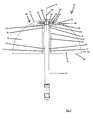
- first embodiment of a device 10 has a holding or fastening device in the form of a carrier 12, by means of which the device 10 can be anchored or fastened, for example, in a pipe or a fireplace or other volume flowed through by a medium.
- the Arrangement of the system can be such that a central axis 14 of the device 10 extends vertically, horizontally or at any angle to the vertical or horizontal. The arrangement is preferably carried out taking into account the flow conditions of the installation site.
- the active element carrier 20 is arranged concentrically around the central axis 14 of the device 10.
- the active elements in the form of the rotary blades 16 are thus arranged rotatably about the central axis 14.
- the central axis 14 is typically the vertical central axis of the device (in a conventional vertical type of installation) which extends in an axial direction of the device 10.
- the vanes 16 are rotatably disposed about the axial (center) axis of the apparatus.
- From theoretical Viewpoint provides a circular configuration of the outer periphery of the rotary wing 16 at a directly and straight away from the active element carrier 20 and the central axis 14 wegersharenden arrangement of the rotary wing 16 has the advantage that they thereby define an at least partially spherical effective volume or span, the spherical shape at a smallest possible surface has the largest possible volume and thus also effective volume.
- the two sides 26, 28 of the rotary blades 16, which connect the active element carrier 20 associated side 22 of the rotary wing 16 with the active element carrier 20 remote from side 24 of the rotary wing 16, have in the present embodiment, a straight outer periphery.
- the rotary blades 16 are connected via a connecting member 30 with a rotor 32 of an electric generator in combination.
- the rotor 32 is arranged between two stators 34, 36 and forms together with these the generator.
- both the rotor 32 and the two stators 34, 36 are disk-shaped and thus form a disk generator.
- a construction may be implemented in which the rotary vanes 16 are in communication with a device for transmitting the rotational movement, for example a shaft, whereby a transmission of rotational movement (mechanical work) to a customer (for example, pump or Drive device for any machine) or, for example, to a transmission for increasing or decreasing the speed is made possible.
- the apparatus 10 further includes a volume 40 defined by a removable housing in which, or in alternative embodiments, portions thereof or components for receiving or transmitting rotational movement are disposed.
- the housing 38 has a portion 42 with an arcuate outer periphery, which forms an uninterrupted outer circumferential line with the active elements.
- a bolt 46 is arranged as an extension of the carrier 12 on one side of the device (as an extension of the carrier 12, which protrudes beyond the device), which may optionally be at least partially threaded, for example it can be locked by means of a nut in a corresponding recess on a component of a system to which the device is to be fastened.
- a dielectric member (insulating member) in the form of a sleeve 48 which is made of an insulating material, and on which the stators 34, 36 of the generator are mounted, is provided.
- a recess 50 is mounted in the carrier 12 for discharging the electrical energy, through which the lines leading to the generator can be guided in the carrier 12 and then guided within this then to a connection point.
- a supporting device in the form of a rotatably mounted wheel 56 is arranged on the side of the housing 38 assigned to the rotary blades 16, which prevents deformation of the rotary-wing support plate unit, especially at higher rotational speeds.
- the connection member 30 is connected to the support plate 52.
- the rotary blades 16 are in this embodiment with the connecting member which establishes the operative connection between the rotary blades 16 and the rotor 32 of the generator, not itself connected, but via the support plate 52 to which the rotary blades 16 are attached.
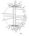
- the second embodiment according to Fig. 2 corresponds to the first embodiment with the exception that according to the second embodiment, the rotary blades 16 of the Act element carrier 20 bent in the radial direction extend outward.
- a center support device in the form of a rotatably mounted wheel 58 which spaces the rotary blade support plate unit of the first device part 10 and the rotary wing support plate unit of the lower device part 10a holds.
- the center support device may also be attached to the corresponding second support plate (in FIG Fig. 3 not shown) of the second device part 10a may be arranged.
- the device 10 ' is designed such that the rotary vanes 16 can only rotate in a first direction of rotation and consequently can only be driven in this direction and the rotary vanes 16a can only rotate in a second direction of rotation opposite to the first direction of rotation and are drivable only in this.
- This provides for angular momentum compensation to occur and, unlike rotation of the rotary vanes 16 and 16a in the same direction, reduced forces (or no forces, depending on whether the rotational speeds of the rotary vanes 16 and 16a are different or equal) act on the carrier 12 ,
- both the rotary vanes 16 and the rotary vanes 16a are driven in the same direction.
- the design of the two device parts 10 and 10a may also be different in alternative embodiments.
- the rotary vanes 16 may extend straight outward from the active element carrier 20 'while the rotary vanes 16a extend outwardly from the active element carrier 20'.
- Other combinations of features that combine the features of the above-described first and second and the alternative embodiments thereof are possible.
- the device 10 comprises a between the first and the second active elements, i. between the first and the second rotary blades 16, 16 a trained volume, in which components of an electric motor, in particular an electric motor in disc design or components for dispensing or for transmitting the rotational movement are arranged.
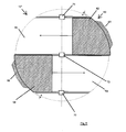
- FIGS. 4 and 5 4 shows a fourth embodiment of a device 10 "according to the invention, which essentially builds on the third embodiment, adding a guide cap 60 having a first guide element 62 and a second guide element 64.
- the guide cover 60 covers portions of the device 10 ", and thus provides a flow guide, as desired.
- the guide cap 60 In order to be able to fix the guide cap 60 accordingly, it has a first fixing device 66, which is assigned to the first guide element 62 and attached thereto, and a second fixing device 68, which is assigned to the second guide element 64 and attached thereto.
- the fixing devices 66, 68 are provided to engage in corresponding recesses, for example on a pipe section.
- the guide elements 62, 64 enclose an angle of approximately 135 °, in order to be able to ensure a flow inlet and a flow outlet as desired.
- the outer peripheral line of the guide elements 62, 64 a Distance from the outer peripheral line of the rotary wings 16, 16a.
- the gap width is in particular approximately 5 to 15 mm, furthermore in particular approximately 10 mm, in order to best prevent flow turbulences between the rotary blades and the guide elements 62, 64.
- the guide cap 60 is, as indicated by rectangles 70, 72 and 74, with the active element carrier 20 (see, for example, Fig. 1 ) rigidly connected.
- the guide cap 60 can be moved relative to the carrier 12 or rotated or can Carrier 12 against the (provided for attachment to a housing) guide cap 60 move. This leads to a lower material load by a compensation of vibrations and the like.
- the guide cap 60 may of course also have only a cover and thus for use in the embodiments according to the FIGS. 1 and 2 and the alternative embodiments described in this context.
- all of the described embodiments may be such that the ratio of the radii of the support plates 52, 54 or the diameter of the support plates 52, 54 gives a value of 0.3 to 0.6, in particular a value of 0.4 (smaller radius divided through the larger radius).
- the rotary vanes may have different radial extents. In particular, an alternating arrangement of rotary blades with a short radial extent and those with a long or wide radial extent is conceivable.
- the rotary wings of all embodiments can be tilted in, i. such that the point of intersection of the side 26 and the side 24 is not in a plane spanned by the remaining three points of intersection of the sides of the vane.
- flow guiding devices which have a different structure than the guide cap 60, are used.
- This can be, for example, according to curved baffles, pipe sections which taper or widen in the direction of the system in diameter or have a constant diameter or even in an inflow or outflow section arranged guide elements of any configuration.
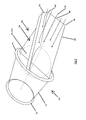
- FIG. 6 shows a further (fifth) possible embodiment of a device 10 "according to the invention
- the fifth embodiment has a device 10 'according to the third embodiment whose position is indicated by a circle 70.
- the device 10 has a first Pipe section 72, which is provided with flanges 74, 76 for attachment to other pipe sections (not shown), on.
- the device further comprises a second pipe section, not shown for reasons of clarity, which is identical to the first pipe section, and is connected thereto.
- the first tube section 72 has, in the region in which the device 10 'is arranged, a first diameter, which is greater than a second diameter, which the tube section 27 has in a region remote from the device 10'.
- a flow guide device 80 is provided in the second tube section, which has a first guide section 82, which in the illustration Fig. 6 is arranged horizontally, and a second, in the illustration according to Fig. 6 vertically arranged guide section 84 which (in the Fig. 6 not shown), the boundary of a full-bodied body, for example made of a lightweight plastic or the like.
- Made to flow line which occupies a limited by the guide portion 84 and the corresponding pipe volume and completely fills, in particular flow turbulence due to a backflow of the medium through the To be able to prevent device through.
- the flow guiding device 80 has a further one in the illustration Fig. 6 vertically arranged, third guide portion (not shown), which is arranged on the underside of the first guide portion 82 and analogous to the second guide defines the boundary of a full-bodied on.
- the second guide portion 84 is disposed on the first guide portion 82 so as to communicate therewith from a point 86 of the guide portion 82 which is on a side of the second tube portion remote from the apparatus 10 '(as indicated by circle 70 above) stands, to the central axis 88 of Guide portion 82 extends on one of the device 10 'adjacent side of the guide portion 82 toward.
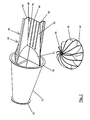
- FIGS. 7 and 8th another possible embodiment of a device according to the invention is shown. This is the fifth, in Fig. 6
- the first guide section extends not only in the second (not shown) pipe section, but also in the first pipe section 72 in order to prevent swirling and undesirable flow effects even when the medium exits to be able to.
- the device according to Figure 6 Also in the pipe section 72 on a second guide section, which in turn limits a full-bodied body together with the corresponding sections of the pipe section 72. This also serves the most untwisted outflow of the medium.
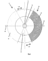
- rotary wing 16 in the sixth embodiment in a plan view cover a full quarter circle, that are not recessed for a corresponding housing.
- the rotary blades 16 extend in the illustrated embodiment bent away from the active element carrier 20, but it is also a straight extension conceivable.
- the rotary vanes have only three sides, one of which is curved or curved. The curved side extends from the active element carrier to the support plate and defines an effective volume which at least partially has a curved surface.
- a gap extending in the axial direction can be arranged between the rotary blades 16, 16a and the active element carrier 20, in particular, a gap extending in the axial direction can be arranged.
- the rotary vanes 16, 16a do not extend in the radial direction as far as the active element carrier 20 or up to the fastening devices with which the rotary vanes 16, 16a are fastened to the active element carrier 20 (rotatable about this).
- the rotary vanes 16, 16a are in this case preferably connected to suitable, for example, strut-shaped or rod-shaped fastening elements which extend in the radial direction and are rotatably arranged on the active element carrier 20 on a side facing away from the rotary vanes 16, 16a, so that the gap (axial gap ) between the rotary blades 16, 16 a and the active element carrier 20 is formed. This gap serves to dissipate a resulting dynamic pressure.
- the device according to the invention does not have to have any active element carrier in further embodiments. If the rotary vanes 16, 16a are fastened to the support plates 52, 54, attachment to the active element support 20, ie a fastening in the region of the central axis 14, can be dispensed with. Thus, the active element carrier 20 is then no longer needed.
- the rotary vanes 16, 16a are then arranged around the support 12 or else optionally, if a design is selected in which the carrier 12 is not or not required in the middle of the effective volume, also radially disposed over the entire diameter of the support plates 52, 54, wherein the rotary blades 16, 16a then corresponding slots, in particular Axial slots, to reduce a dynamic pressure may have. Furthermore, it is also conceivable in these embodiments that the rotary vanes 16, 16a have in particular alternately different radial extensions to the outside. Alternatively, it is conceivable not to include the support plates 52, 54 in the construction, when the rotary vanes 16, 16 a are attached to the active element carrier 20.
- active elements in the form of rotary vanes 16, 16a are arranged rotatable about an axis of rotation (in the described embodiments, the axis of rotation is the central axis of the active element carrier 20, on which the rotary vanes 16, 16a are rotatably arranged, respectively) the central axis of the device 10, 10 ').
- the rotary vanes 16, 16a extend radially away from the axis of rotation, whereby they can extend straight, curved and in each case tilted or not tilted away from the axis of rotation.
- the rotary vanes 16, 16 a On its side facing away from the axis of rotation, the rotary vanes 16, 16 a on a curved or curved outer periphery, it being noted at this point that the curved or curved, in particular circular arc, circular or ellipsoidal arc-shaped outer periphery may extend up to the axis of rotation, such that the rotary vanes with the axis of rotation enclose a circular sector or an ellipse sector or another surface defined by a curved outer circumference such that the rotary vanes 16, 16 a have two approximately straight sides and a curved side.
- the rotary vanes 16, 16a define a volume which has a curved surface, for example a sphere or an ellipsoidally limited volume, which is available as effective volume and ensures good energy utilization.
Landscapes
- Engineering & Computer Science (AREA)
- Combustion & Propulsion (AREA)
- General Engineering & Computer Science (AREA)
- Mechanical Engineering (AREA)
- Chemical & Material Sciences (AREA)
- Sustainable Energy (AREA)
- Life Sciences & Earth Sciences (AREA)
- Sustainable Development (AREA)
- Physics & Mathematics (AREA)
- Fluid Mechanics (AREA)
- Wind Motors (AREA)
- Physical Or Chemical Processes And Apparatus (AREA)
- Other Liquid Machine Or Engine Such As Wave Power Use (AREA)
- Structures Of Non-Positive Displacement Pumps (AREA)
Applications Claiming Priority (4)
| Application Number | Priority Date | Filing Date | Title |
|---|---|---|---|
| DE102011012189 | 2011-02-23 | ||
| DE102011012188 | 2011-02-23 | ||
| DE102011012168 | 2011-02-23 | ||
| DE102011107673A DE102011107673A1 (de) | 2011-02-23 | 2011-07-13 | Vorrichtung zur Energieumwandlung |
Publications (2)
| Publication Number | Publication Date |
|---|---|
| EP2492495A2 true EP2492495A2 (fr) | 2012-08-29 |
| EP2492495A3 EP2492495A3 (fr) | 2017-04-26 |
Family
ID=46671448
Family Applications (1)
| Application Number | Title | Priority Date | Filing Date |
|---|---|---|---|
| EP12001209.1A Withdrawn EP2492495A3 (fr) | 2011-02-23 | 2012-02-23 | Dispositif de conversion d'énergie |
Country Status (2)
| Country | Link |
|---|---|
| EP (1) | EP2492495A3 (fr) |
| DE (2) | DE102011107672A1 (fr) |
Family Cites Families (21)
| Publication number | Priority date | Publication date | Assignee | Title |
|---|---|---|---|---|
| US372148A (en) * | 1887-10-25 | Windmill | ||
| US2439575A (en) * | 1945-05-17 | 1948-04-13 | John M Morris | Current wheel |
| US4115032A (en) * | 1977-03-07 | 1978-09-19 | Heinz Lange | Windmill rotor |
| DE3832851A1 (de) * | 1988-09-28 | 1989-07-27 | Cornelius P Zimmer | Horizontal-windfluegel-rotor |
| GB2298681B (en) * | 1993-11-19 | 1997-07-09 | Le Baigue Research Ltd | Blade profile for wind turbine |
| US5836800A (en) * | 1997-04-03 | 1998-11-17 | Liu; Chin-Hsiang | Pinwheel |
| DE19859865B4 (de) * | 1998-12-23 | 2006-11-09 | Renate Lange | Windkonverter |
| DE29907940U1 (de) | 1999-05-05 | 1999-08-12 | Themel, Ramona, 08060 Zwickau | Windkraftanlage mit Vertikalrotor |
| DE10044147A1 (de) | 2000-09-07 | 2002-03-21 | Paul Graumann | Rotorsystem zur Nutzung von Windenergie nach dem erodynamischen Auftriebsprinzip |
| DE202005009164U1 (de) * | 2005-06-10 | 2006-10-26 | Mp Newco Gmbh | Vertikalachsen-Windrad System |
| US7303369B2 (en) * | 2005-10-31 | 2007-12-04 | Rowan James A | Magnetic vertical axis wind turbine |
| US20080007068A1 (en) * | 2006-07-10 | 2008-01-10 | Rogers Ward | Spherical wind turbine for generating electricity |
| DE102006040006A1 (de) * | 2006-08-25 | 2008-03-20 | Alfred Frohnert | Windturbine mit vertikaler Doppelachse |
| US20080265584A1 (en) * | 2007-04-25 | 2008-10-30 | Chwei-Jie Tsay | Wind driven generator |
| US7777361B2 (en) * | 2008-01-23 | 2010-08-17 | Chen-Hui Hsieh | Turbine ventilator for generating electricity |
| PT103961B (pt) * | 2008-02-08 | 2010-02-08 | Sergio Emanuel Pereir Sequeira | Gerador eólico |
| DE202008007821U1 (de) * | 2008-06-11 | 2009-02-26 | Turan, Selámi | System von mehreren vertikalen Rotorblättern |
| DE102008051255A1 (de) | 2008-10-10 | 2010-04-15 | Martin, Günter | Die Erfindung betrifft einen Windrotor mit speziell angeordneten und geformten Rotorschaufeln mit zusätzlichen Satelliten, die als Auftriebs-Leitbleche ausgeführt sind und sich um eine Achse drehen |
| DE202008013803U1 (de) * | 2008-11-27 | 2010-02-11 | Zimmer, Detlef | Vorrichtung zum Umsetzen der Strömungsenergie von Fließgewässern |
| WO2010071927A1 (fr) * | 2008-12-24 | 2010-07-01 | Digislide Holdings Limited | Turbogénératrice en ligne |
| US8487470B2 (en) * | 2009-05-22 | 2013-07-16 | Derek Grassman | Vertical axis wind turbine and generator therefore |
-
2011
- 2011-07-13 DE DE102011107672A patent/DE102011107672A1/de not_active Withdrawn
- 2011-07-13 DE DE102011107673A patent/DE102011107673A1/de not_active Withdrawn
-
2012
- 2012-02-23 EP EP12001209.1A patent/EP2492495A3/fr not_active Withdrawn
Non-Patent Citations (1)
| Title |
|---|
| None |
Also Published As
| Publication number | Publication date |
|---|---|
| EP2492495A3 (fr) | 2017-04-26 |
| DE102011107672A1 (de) | 2012-09-06 |
| DE102011107673A1 (de) | 2012-09-06 |
Similar Documents
| Publication | Publication Date | Title |
|---|---|---|
| EP1002949A2 (fr) | Eolienne à axe vertical | |
| EP3550140B1 (fr) | Support de machine pour éolienne | |
| DE2948060A1 (de) | Vorrichtung zur umwandlung von windenergie | |
| EP2926013A2 (fr) | Dispositif de ventilation et véhicule pourvu d'un dispositif de ventilation | |
| DE102013107580A1 (de) | Diagonal-Ventilator | |
| WO2016174146A1 (fr) | Système d'organe d'agitation | |
| EP2219917A2 (fr) | Pompe à vide | |
| DE102008021683A1 (de) | Rotierende Einheit für einen Axialkompressor | |
| EP2174003A2 (fr) | Dispositif de production d'énergie à partir d'un courant de fluide | |
| DE102011121925A1 (de) | Verdichter und Verfahren zum Betrieb eines Verdichters | |
| DE102019213315A1 (de) | Ventilator | |
| EP2492495A2 (fr) | Dispositif de conversion d'énergie | |
| DE102014017372A1 (de) | Pumpturbine sowie Pumpspeicherkraftwerk mit einer solchen Pumpturbine | |
| DE102014215560A1 (de) | Gasverdichter, insbesondere für ein Brennstoffzellensystem eines Fahrzeugs | |
| WO1989007713A1 (fr) | Eolienne | |
| DE102009060763A1 (de) | Geometrische Anordnung von Teilen eines Energiewandlers | |
| DE649668C (de) | Laeufer fuer hydraulische Maschinen | |
| DE10340112A1 (de) | Windkraftanlage | |
| EP2492510A2 (fr) | Dispositif de conversion d'énergie | |
| DE112023001556T5 (de) | Variable einlassleitschaufelvorrichtung und kompressor mit dieser | |
| DE102013216334A1 (de) | Drehmomentübertragendes Bauteil eines Getriebes | |
| DE102008057532B4 (de) | Ladeeinrichtung | |
| EP3205884B1 (fr) | Système de rotor à vide auto-pompant | |
| DE20108925U1 (de) | Strömungsenergieanlage, insbesondere Windkraftanlage | |
| DE202012102147U1 (de) | Vorrichtung zur Verstellung eines Rotorblatts |
Legal Events
| Date | Code | Title | Description |
|---|---|---|---|
| PUAI | Public reference made under article 153(3) epc to a published international application that has entered the european phase |
Free format text: ORIGINAL CODE: 0009012 |
|
| AK | Designated contracting states |
Kind code of ref document: A2 Designated state(s): AL AT BE BG CH CY CZ DE DK EE ES FI FR GB GR HR HU IE IS IT LI LT LU LV MC MK MT NL NO PL PT RO RS SE SI SK SM TR |
|
| AX | Request for extension of the european patent |
Extension state: BA ME |
|
| PUAL | Search report despatched |
Free format text: ORIGINAL CODE: 0009013 |
|
| AK | Designated contracting states |
Kind code of ref document: A3 Designated state(s): AL AT BE BG CH CY CZ DE DK EE ES FI FR GB GR HR HU IE IS IT LI LT LU LV MC MK MT NL NO PL PT RO RS SE SI SK SM TR |
|
| AX | Request for extension of the european patent |
Extension state: BA ME |
|
| RIC1 | Information provided on ipc code assigned before grant |
Ipc: F03D 3/00 20060101ALI20170320BHEP Ipc: F03B 3/12 20060101AFI20170320BHEP |
|
| STAA | Information on the status of an ep patent application or granted ep patent |
Free format text: STATUS: THE APPLICATION IS DEEMED TO BE WITHDRAWN |
|
| 18D | Application deemed to be withdrawn |
Effective date: 20170901 |