EP2492495A2 - Device for energy conversion - Google Patents
Device for energy conversion Download PDFInfo
- Publication number
- EP2492495A2 EP2492495A2 EP12001209A EP12001209A EP2492495A2 EP 2492495 A2 EP2492495 A2 EP 2492495A2 EP 12001209 A EP12001209 A EP 12001209A EP 12001209 A EP12001209 A EP 12001209A EP 2492495 A2 EP2492495 A2 EP 2492495A2
- Authority
- EP
- European Patent Office
- Prior art keywords
- active elements
- energy
- kinetic energy
- curved
- element carrier
- Prior art date
- Legal status (The legal status is an assumption and is not a legal conclusion. Google has not performed a legal analysis and makes no representation as to the accuracy of the status listed.)
- Withdrawn
Links
Images


Classifications
-
- F—MECHANICAL ENGINEERING; LIGHTING; HEATING; WEAPONS; BLASTING
- F03—MACHINES OR ENGINES FOR LIQUIDS; WIND, SPRING, OR WEIGHT MOTORS; PRODUCING MECHANICAL POWER OR A REACTIVE PROPULSIVE THRUST, NOT OTHERWISE PROVIDED FOR
- F03D—WIND MOTORS
- F03D3/00—Wind motors with rotation axis substantially perpendicular to the air flow entering the rotor
- F03D3/02—Wind motors with rotation axis substantially perpendicular to the air flow entering the rotor having a plurality of rotors
-
- F—MECHANICAL ENGINEERING; LIGHTING; HEATING; WEAPONS; BLASTING
- F03—MACHINES OR ENGINES FOR LIQUIDS; WIND, SPRING, OR WEIGHT MOTORS; PRODUCING MECHANICAL POWER OR A REACTIVE PROPULSIVE THRUST, NOT OTHERWISE PROVIDED FOR
- F03B—MACHINES OR ENGINES FOR LIQUIDS
- F03B3/00—Machines or engines of reaction type; Parts or details peculiar thereto
- F03B3/12—Blades; Blade-carrying rotors
- F03B3/121—Blades, their form or construction
-
- F—MECHANICAL ENGINEERING; LIGHTING; HEATING; WEAPONS; BLASTING
- F03—MACHINES OR ENGINES FOR LIQUIDS; WIND, SPRING, OR WEIGHT MOTORS; PRODUCING MECHANICAL POWER OR A REACTIVE PROPULSIVE THRUST, NOT OTHERWISE PROVIDED FOR
- F03D—WIND MOTORS
- F03D3/00—Wind motors with rotation axis substantially perpendicular to the air flow entering the rotor
- F03D3/005—Wind motors with rotation axis substantially perpendicular to the air flow entering the rotor the axis being vertical
-
- F—MECHANICAL ENGINEERING; LIGHTING; HEATING; WEAPONS; BLASTING
- F03—MACHINES OR ENGINES FOR LIQUIDS; WIND, SPRING, OR WEIGHT MOTORS; PRODUCING MECHANICAL POWER OR A REACTIVE PROPULSIVE THRUST, NOT OTHERWISE PROVIDED FOR
- F03D—WIND MOTORS
- F03D3/00—Wind motors with rotation axis substantially perpendicular to the air flow entering the rotor
- F03D3/06—Rotors
- F03D3/061—Rotors characterised by their aerodynamic shape, e.g. aerofoil profiles
-
- F—MECHANICAL ENGINEERING; LIGHTING; HEATING; WEAPONS; BLASTING
- F05—INDEXING SCHEMES RELATING TO ENGINES OR PUMPS IN VARIOUS SUBCLASSES OF CLASSES F01-F04
- F05B—INDEXING SCHEME RELATING TO WIND, SPRING, WEIGHT, INERTIA OR LIKE MOTORS, TO MACHINES OR ENGINES FOR LIQUIDS COVERED BY SUBCLASSES F03B, F03D AND F03G
- F05B2220/00—Application
- F05B2220/60—Application making use of surplus or waste energy
- F05B2220/602—Application making use of surplus or waste energy with energy recovery turbines
-
- F—MECHANICAL ENGINEERING; LIGHTING; HEATING; WEAPONS; BLASTING
- F05—INDEXING SCHEMES RELATING TO ENGINES OR PUMPS IN VARIOUS SUBCLASSES OF CLASSES F01-F04
- F05B—INDEXING SCHEME RELATING TO WIND, SPRING, WEIGHT, INERTIA OR LIKE MOTORS, TO MACHINES OR ENGINES FOR LIQUIDS COVERED BY SUBCLASSES F03B, F03D AND F03G
- F05B2240/00—Components
- F05B2240/20—Rotors
- F05B2240/21—Rotors for wind turbines
- F05B2240/211—Rotors for wind turbines with vertical axis
-
- F—MECHANICAL ENGINEERING; LIGHTING; HEATING; WEAPONS; BLASTING
- F05—INDEXING SCHEMES RELATING TO ENGINES OR PUMPS IN VARIOUS SUBCLASSES OF CLASSES F01-F04
- F05B—INDEXING SCHEME RELATING TO WIND, SPRING, WEIGHT, INERTIA OR LIKE MOTORS, TO MACHINES OR ENGINES FOR LIQUIDS COVERED BY SUBCLASSES F03B, F03D AND F03G
- F05B2250/00—Geometry
- F05B2250/10—Geometry two-dimensional
- F05B2250/14—Geometry two-dimensional elliptical
- F05B2250/141—Geometry two-dimensional elliptical circular
-
- F—MECHANICAL ENGINEERING; LIGHTING; HEATING; WEAPONS; BLASTING
- F05—INDEXING SCHEMES RELATING TO ENGINES OR PUMPS IN VARIOUS SUBCLASSES OF CLASSES F01-F04
- F05B—INDEXING SCHEME RELATING TO WIND, SPRING, WEIGHT, INERTIA OR LIKE MOTORS, TO MACHINES OR ENGINES FOR LIQUIDS COVERED BY SUBCLASSES F03B, F03D AND F03G
- F05B2250/00—Geometry
- F05B2250/20—Geometry three-dimensional
- F05B2250/24—Geometry three-dimensional ellipsoidal
- F05B2250/241—Geometry three-dimensional ellipsoidal spherical
-
- Y—GENERAL TAGGING OF NEW TECHNOLOGICAL DEVELOPMENTS; GENERAL TAGGING OF CROSS-SECTIONAL TECHNOLOGIES SPANNING OVER SEVERAL SECTIONS OF THE IPC; TECHNICAL SUBJECTS COVERED BY FORMER USPC CROSS-REFERENCE ART COLLECTIONS [XRACs] AND DIGESTS
- Y02—TECHNOLOGIES OR APPLICATIONS FOR MITIGATION OR ADAPTATION AGAINST CLIMATE CHANGE
- Y02B—CLIMATE CHANGE MITIGATION TECHNOLOGIES RELATED TO BUILDINGS, e.g. HOUSING, HOUSE APPLIANCES OR RELATED END-USER APPLICATIONS
- Y02B10/00—Integration of renewable energy sources in buildings
- Y02B10/50—Hydropower in dwellings
-
- Y—GENERAL TAGGING OF NEW TECHNOLOGICAL DEVELOPMENTS; GENERAL TAGGING OF CROSS-SECTIONAL TECHNOLOGIES SPANNING OVER SEVERAL SECTIONS OF THE IPC; TECHNICAL SUBJECTS COVERED BY FORMER USPC CROSS-REFERENCE ART COLLECTIONS [XRACs] AND DIGESTS
- Y02—TECHNOLOGIES OR APPLICATIONS FOR MITIGATION OR ADAPTATION AGAINST CLIMATE CHANGE
- Y02E—REDUCTION OF GREENHOUSE GAS [GHG] EMISSIONS, RELATED TO ENERGY GENERATION, TRANSMISSION OR DISTRIBUTION
- Y02E10/00—Energy generation through renewable energy sources
- Y02E10/20—Hydro energy
-
- Y—GENERAL TAGGING OF NEW TECHNOLOGICAL DEVELOPMENTS; GENERAL TAGGING OF CROSS-SECTIONAL TECHNOLOGIES SPANNING OVER SEVERAL SECTIONS OF THE IPC; TECHNICAL SUBJECTS COVERED BY FORMER USPC CROSS-REFERENCE ART COLLECTIONS [XRACs] AND DIGESTS
- Y02—TECHNOLOGIES OR APPLICATIONS FOR MITIGATION OR ADAPTATION AGAINST CLIMATE CHANGE
- Y02E—REDUCTION OF GREENHOUSE GAS [GHG] EMISSIONS, RELATED TO ENERGY GENERATION, TRANSMISSION OR DISTRIBUTION
- Y02E10/00—Energy generation through renewable energy sources
- Y02E10/70—Wind energy
- Y02E10/74—Wind turbines with rotation axis perpendicular to the wind direction
Definitions
- the present invention relates to a device for recovering energy from a flowing medium, in particular a fluid or a granular medium, or a charged with kinetic energy solid according to the preamble of patent claim 1.
- Devices for energy recovery from a flowing medium in particular a fluid or a granular medium, or a charged with kinetic energy solids are known for example from the heating or ventilation technology.
- the heat energy contained in an exhaust gas or an exhaust air is generally removed via heat exchangers the exhaust gas or the exhaust air and then fed to a further use, for example, the heating of a room air.
- the device according to the invention for recovering energy from a flowing medium, in particular a fluid or a granular medium, or a solid acted upon by kinetic energy for this purpose has a device for converting kinetic energy of a fluid, a granular medium or a solid into kinetic energy, in particular Rotational energy, of a solid body.
- a device according to the invention in combination with heat exchangers, i. It is also possible to arrange one or more heat exchangers in the device according to the invention in order to further improve the efficiency of the device.
- Such a device can, as already explained above, also have components which deprive the medium of other forms of energy (for example thermal energy), but for the sake of simplification it is assumed that the device is only a device for converting the flow energy or kinetic energy of a fluid , a granular medium or a solid in kinetic energy, in particular rotational energy, of a solid body.
- other forms of energy for example thermal energy
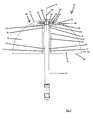
- first embodiment of a device 10 has a holding or fastening device in the form of a carrier 12, by means of which the device 10 can be anchored or fastened, for example, in a pipe or a fireplace or other volume flowed through by a medium.
- the Arrangement of the system can be such that a central axis 14 of the device 10 extends vertically, horizontally or at any angle to the vertical or horizontal. The arrangement is preferably carried out taking into account the flow conditions of the installation site.
- the active element carrier 20 is arranged concentrically around the central axis 14 of the device 10.
- the active elements in the form of the rotary blades 16 are thus arranged rotatably about the central axis 14.
- the central axis 14 is typically the vertical central axis of the device (in a conventional vertical type of installation) which extends in an axial direction of the device 10.
- the vanes 16 are rotatably disposed about the axial (center) axis of the apparatus.
- From theoretical Viewpoint provides a circular configuration of the outer periphery of the rotary wing 16 at a directly and straight away from the active element carrier 20 and the central axis 14 wegersharenden arrangement of the rotary wing 16 has the advantage that they thereby define an at least partially spherical effective volume or span, the spherical shape at a smallest possible surface has the largest possible volume and thus also effective volume.
- the two sides 26, 28 of the rotary blades 16, which connect the active element carrier 20 associated side 22 of the rotary wing 16 with the active element carrier 20 remote from side 24 of the rotary wing 16, have in the present embodiment, a straight outer periphery.
- the rotary blades 16 are connected via a connecting member 30 with a rotor 32 of an electric generator in combination.
- the rotor 32 is arranged between two stators 34, 36 and forms together with these the generator.
- both the rotor 32 and the two stators 34, 36 are disk-shaped and thus form a disk generator.
- a construction may be implemented in which the rotary vanes 16 are in communication with a device for transmitting the rotational movement, for example a shaft, whereby a transmission of rotational movement (mechanical work) to a customer (for example, pump or Drive device for any machine) or, for example, to a transmission for increasing or decreasing the speed is made possible.
- the apparatus 10 further includes a volume 40 defined by a removable housing in which, or in alternative embodiments, portions thereof or components for receiving or transmitting rotational movement are disposed.
- the housing 38 has a portion 42 with an arcuate outer periphery, which forms an uninterrupted outer circumferential line with the active elements.
- a bolt 46 is arranged as an extension of the carrier 12 on one side of the device (as an extension of the carrier 12, which protrudes beyond the device), which may optionally be at least partially threaded, for example it can be locked by means of a nut in a corresponding recess on a component of a system to which the device is to be fastened.
- a dielectric member (insulating member) in the form of a sleeve 48 which is made of an insulating material, and on which the stators 34, 36 of the generator are mounted, is provided.
- a recess 50 is mounted in the carrier 12 for discharging the electrical energy, through which the lines leading to the generator can be guided in the carrier 12 and then guided within this then to a connection point.
- a supporting device in the form of a rotatably mounted wheel 56 is arranged on the side of the housing 38 assigned to the rotary blades 16, which prevents deformation of the rotary-wing support plate unit, especially at higher rotational speeds.
- the connection member 30 is connected to the support plate 52.
- the rotary blades 16 are in this embodiment with the connecting member which establishes the operative connection between the rotary blades 16 and the rotor 32 of the generator, not itself connected, but via the support plate 52 to which the rotary blades 16 are attached.
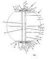
- the second embodiment according to Fig. 2 corresponds to the first embodiment with the exception that according to the second embodiment, the rotary blades 16 of the Act element carrier 20 bent in the radial direction extend outward.
- a center support device in the form of a rotatably mounted wheel 58 which spaces the rotary blade support plate unit of the first device part 10 and the rotary wing support plate unit of the lower device part 10a holds.
- the center support device may also be attached to the corresponding second support plate (in FIG Fig. 3 not shown) of the second device part 10a may be arranged.
- the device 10 ' is designed such that the rotary vanes 16 can only rotate in a first direction of rotation and consequently can only be driven in this direction and the rotary vanes 16a can only rotate in a second direction of rotation opposite to the first direction of rotation and are drivable only in this.
- This provides for angular momentum compensation to occur and, unlike rotation of the rotary vanes 16 and 16a in the same direction, reduced forces (or no forces, depending on whether the rotational speeds of the rotary vanes 16 and 16a are different or equal) act on the carrier 12 ,
- both the rotary vanes 16 and the rotary vanes 16a are driven in the same direction.
- the design of the two device parts 10 and 10a may also be different in alternative embodiments.
- the rotary vanes 16 may extend straight outward from the active element carrier 20 'while the rotary vanes 16a extend outwardly from the active element carrier 20'.
- Other combinations of features that combine the features of the above-described first and second and the alternative embodiments thereof are possible.
- the device 10 comprises a between the first and the second active elements, i. between the first and the second rotary blades 16, 16 a trained volume, in which components of an electric motor, in particular an electric motor in disc design or components for dispensing or for transmitting the rotational movement are arranged.
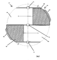
- FIGS. 4 and 5 4 shows a fourth embodiment of a device 10 "according to the invention, which essentially builds on the third embodiment, adding a guide cap 60 having a first guide element 62 and a second guide element 64.
- the guide cover 60 covers portions of the device 10 ", and thus provides a flow guide, as desired.
- the guide cap 60 In order to be able to fix the guide cap 60 accordingly, it has a first fixing device 66, which is assigned to the first guide element 62 and attached thereto, and a second fixing device 68, which is assigned to the second guide element 64 and attached thereto.
- the fixing devices 66, 68 are provided to engage in corresponding recesses, for example on a pipe section.
- the guide elements 62, 64 enclose an angle of approximately 135 °, in order to be able to ensure a flow inlet and a flow outlet as desired.
- the outer peripheral line of the guide elements 62, 64 a Distance from the outer peripheral line of the rotary wings 16, 16a.
- the gap width is in particular approximately 5 to 15 mm, furthermore in particular approximately 10 mm, in order to best prevent flow turbulences between the rotary blades and the guide elements 62, 64.
- the guide cap 60 is, as indicated by rectangles 70, 72 and 74, with the active element carrier 20 (see, for example, Fig. 1 ) rigidly connected.
- the guide cap 60 can be moved relative to the carrier 12 or rotated or can Carrier 12 against the (provided for attachment to a housing) guide cap 60 move. This leads to a lower material load by a compensation of vibrations and the like.
- the guide cap 60 may of course also have only a cover and thus for use in the embodiments according to the FIGS. 1 and 2 and the alternative embodiments described in this context.
- all of the described embodiments may be such that the ratio of the radii of the support plates 52, 54 or the diameter of the support plates 52, 54 gives a value of 0.3 to 0.6, in particular a value of 0.4 (smaller radius divided through the larger radius).
- the rotary vanes may have different radial extents. In particular, an alternating arrangement of rotary blades with a short radial extent and those with a long or wide radial extent is conceivable.
- the rotary wings of all embodiments can be tilted in, i. such that the point of intersection of the side 26 and the side 24 is not in a plane spanned by the remaining three points of intersection of the sides of the vane.
- flow guiding devices which have a different structure than the guide cap 60, are used.
- This can be, for example, according to curved baffles, pipe sections which taper or widen in the direction of the system in diameter or have a constant diameter or even in an inflow or outflow section arranged guide elements of any configuration.
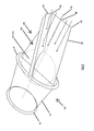
- FIG. 6 shows a further (fifth) possible embodiment of a device 10 "according to the invention
- the fifth embodiment has a device 10 'according to the third embodiment whose position is indicated by a circle 70.
- the device 10 has a first Pipe section 72, which is provided with flanges 74, 76 for attachment to other pipe sections (not shown), on.
- the device further comprises a second pipe section, not shown for reasons of clarity, which is identical to the first pipe section, and is connected thereto.
- the first tube section 72 has, in the region in which the device 10 'is arranged, a first diameter, which is greater than a second diameter, which the tube section 27 has in a region remote from the device 10'.
- a flow guide device 80 is provided in the second tube section, which has a first guide section 82, which in the illustration Fig. 6 is arranged horizontally, and a second, in the illustration according to Fig. 6 vertically arranged guide section 84 which (in the Fig. 6 not shown), the boundary of a full-bodied body, for example made of a lightweight plastic or the like.
- Made to flow line which occupies a limited by the guide portion 84 and the corresponding pipe volume and completely fills, in particular flow turbulence due to a backflow of the medium through the To be able to prevent device through.
- the flow guiding device 80 has a further one in the illustration Fig. 6 vertically arranged, third guide portion (not shown), which is arranged on the underside of the first guide portion 82 and analogous to the second guide defines the boundary of a full-bodied on.
- the second guide portion 84 is disposed on the first guide portion 82 so as to communicate therewith from a point 86 of the guide portion 82 which is on a side of the second tube portion remote from the apparatus 10 '(as indicated by circle 70 above) stands, to the central axis 88 of Guide portion 82 extends on one of the device 10 'adjacent side of the guide portion 82 toward.
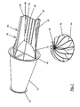
- FIGS. 7 and 8th another possible embodiment of a device according to the invention is shown. This is the fifth, in Fig. 6
- the first guide section extends not only in the second (not shown) pipe section, but also in the first pipe section 72 in order to prevent swirling and undesirable flow effects even when the medium exits to be able to.
- the device according to Figure 6 Also in the pipe section 72 on a second guide section, which in turn limits a full-bodied body together with the corresponding sections of the pipe section 72. This also serves the most untwisted outflow of the medium.
- rotary wing 16 in the sixth embodiment in a plan view cover a full quarter circle, that are not recessed for a corresponding housing.
- the rotary blades 16 extend in the illustrated embodiment bent away from the active element carrier 20, but it is also a straight extension conceivable.
- the rotary vanes have only three sides, one of which is curved or curved. The curved side extends from the active element carrier to the support plate and defines an effective volume which at least partially has a curved surface.
- a gap extending in the axial direction can be arranged between the rotary blades 16, 16a and the active element carrier 20, in particular, a gap extending in the axial direction can be arranged.
- the rotary vanes 16, 16a do not extend in the radial direction as far as the active element carrier 20 or up to the fastening devices with which the rotary vanes 16, 16a are fastened to the active element carrier 20 (rotatable about this).
- the rotary vanes 16, 16a are in this case preferably connected to suitable, for example, strut-shaped or rod-shaped fastening elements which extend in the radial direction and are rotatably arranged on the active element carrier 20 on a side facing away from the rotary vanes 16, 16a, so that the gap (axial gap ) between the rotary blades 16, 16 a and the active element carrier 20 is formed. This gap serves to dissipate a resulting dynamic pressure.
- the device according to the invention does not have to have any active element carrier in further embodiments. If the rotary vanes 16, 16a are fastened to the support plates 52, 54, attachment to the active element support 20, ie a fastening in the region of the central axis 14, can be dispensed with. Thus, the active element carrier 20 is then no longer needed.
- the rotary vanes 16, 16a are then arranged around the support 12 or else optionally, if a design is selected in which the carrier 12 is not or not required in the middle of the effective volume, also radially disposed over the entire diameter of the support plates 52, 54, wherein the rotary blades 16, 16a then corresponding slots, in particular Axial slots, to reduce a dynamic pressure may have. Furthermore, it is also conceivable in these embodiments that the rotary vanes 16, 16a have in particular alternately different radial extensions to the outside. Alternatively, it is conceivable not to include the support plates 52, 54 in the construction, when the rotary vanes 16, 16 a are attached to the active element carrier 20.
- active elements in the form of rotary vanes 16, 16a are arranged rotatable about an axis of rotation (in the described embodiments, the axis of rotation is the central axis of the active element carrier 20, on which the rotary vanes 16, 16a are rotatably arranged, respectively) the central axis of the device 10, 10 ').
- the rotary vanes 16, 16a extend radially away from the axis of rotation, whereby they can extend straight, curved and in each case tilted or not tilted away from the axis of rotation.
- the rotary vanes 16, 16 a On its side facing away from the axis of rotation, the rotary vanes 16, 16 a on a curved or curved outer periphery, it being noted at this point that the curved or curved, in particular circular arc, circular or ellipsoidal arc-shaped outer periphery may extend up to the axis of rotation, such that the rotary vanes with the axis of rotation enclose a circular sector or an ellipse sector or another surface defined by a curved outer circumference such that the rotary vanes 16, 16 a have two approximately straight sides and a curved side.
- the rotary vanes 16, 16a define a volume which has a curved surface, for example a sphere or an ellipsoidally limited volume, which is available as effective volume and ensures good energy utilization.
Landscapes
- Engineering & Computer Science (AREA)
- Combustion & Propulsion (AREA)
- General Engineering & Computer Science (AREA)
- Mechanical Engineering (AREA)
- Chemical & Material Sciences (AREA)
- Sustainable Energy (AREA)
- Life Sciences & Earth Sciences (AREA)
- Sustainable Development (AREA)
- Physics & Mathematics (AREA)
- Fluid Mechanics (AREA)
- Wind Motors (AREA)
- Physical Or Chemical Processes And Apparatus (AREA)
- Other Liquid Machine Or Engine Such As Wave Power Use (AREA)
- Structures Of Non-Positive Displacement Pumps (AREA)
Abstract
Description
Die vorliegende Erfindung betrifft eine Vorrichtung zur Energierückgewinnung aus einem strömenden Medium, insbesondere einem Fluid oder einem granularen Medium, oder einem mit kinetischer Energie beaufschlagten Festkörper gemäß dem Oberbegriff des Patentanspruchs 1.The present invention relates to a device for recovering energy from a flowing medium, in particular a fluid or a granular medium, or a charged with kinetic energy solid according to the preamble of
Vorrichtungen zur Energierückgewinnung aus einem strömenden Medium, insbesondere einem Fluid oder einem granularen Medium, oder einem mit kinetischer Energie beaufschlagten Festkörper sind beispielsweise aus der Heizungs- oder Lüftungstechnik bekannt.Devices for energy recovery from a flowing medium, in particular a fluid or a granular medium, or a charged with kinetic energy solids are known for example from the heating or ventilation technology.
In derartigen Anlagen wird im Allgemeinen die in einem Abgas oder einer Abluft enthaltene Wärmeenergie über Wärmetauscher dem Abgas oder der Abluft entzogen und dann einer weiteren Verwendung, beispielsweise der Erwärmung einer Raumluft zugeführt.In such systems, the heat energy contained in an exhaust gas or an exhaust air is generally removed via heat exchangers the exhaust gas or the exhaust air and then fed to a further use, for example, the heating of a room air.
Eine Konstruktion mit Wärmetauschern ist jedoch relativ komplex. Ferner ist es mit einer derartigen Konstruktion nur möglich, dem abzuführenden Abgas oder der abzuführenden Luft Wärmeenergie zu entziehen, was zu einem begrenzten Wirkungsgrad führt. Der Einsatz solcher Anlagen ist ferner im Allgemeinen auf eine Energierückgewinnung in Gasen beschränkt.However, a construction with heat exchangers is relatively complex. Further, with such a construction, it is only possible to extract heat energy from the exhaust gas or the air to be discharged, resulting in a limited efficiency. Of the Use of such equipment is also generally limited to energy recovery in gases.
Demnach ist es Aufgabe der vorliegenden Erfindung, eine Vorrichtung zur Verfügung zu stellen, die einen Wirkungsgrad einer Energierückgewinnungsvorrichtung erhöhen kann und dabei konstruktiv möglichst einfach aufgebaut ist. Ferner soll diese Vorrichtung nicht nur für Gase, sondern auch für Fluide, granulare Medien und auch für Festkörper geeignet sein.Accordingly, it is an object of the present invention to provide a device that can increase the efficiency of an energy recovery device and is constructed constructively as simple as possible. Furthermore, this device should not only be suitable for gases but also for fluids, granular media and also for solids.
Diese Aufgabe wird erfindungsgemäß durch eine Vorrichtung gemäß dem Patentanspruch 1 gelöst. Die erfindungsgemäße Vorrichtung zur Energierückgewinnung aus einem strömenden Medium, insbesondere einem Fluid oder einem granularen Medium, oder einem mit kinetischer Energie beaufschlagten Festkörper weist dazu eine Vorrichtung zur Umwandlung von Strömungsenergie oder kinetischer Energie eines Fluids, eines granularen Mediums oder eines Festkörpers in kinetische Energie, insbesondere Rotationsenergie, eines festen Körpers auf. Durch die Ausnutzung der Strömungsenergie bzw. der kinetischen Energie des Mediums, welchem Energie entzogen werden soll, ist der Einsatzbereich einer derartigen Vorrichtung im Gegensatz zu Vorrichtungen mit Wärmetauschern deutlich erweitert. Es ist auch eine Verwendung einer erfindungsgemäßen Vorrichtung in Kombination mit Wärmetauschern möglich, d.h. es können auch ein oder mehrere Wärmetauscher in der erfindungsgemäßen Vorrichtung angeordnet werden, um den Wirkungsgrad der Vorrichtung weiter zu verbessern.This object is achieved by a device according to
Weitere Merkmale der Erfindung sind in den Unteransprüchen angegeben.Further features of the invention are specified in the subclaims.
Die Erfindung wird im Folgenden mit Bezug auf die beiliegenden Zeichnungen anhand von bevorzugten Ausführungsformen beispielhaft beschrieben. In den Zeichnungen zeigen
-
Fig. 1 eine erste Ausführungsform einer erfindungsgemäßen Vorrichtung in einer schematischen Querschnittsdarstellung; -
Fig. 2 eine zweite Ausführungsform in einer modellhaften fotografischen Darstellung in Seitenansicht; -
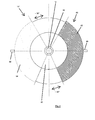
Fig. 3 eine dritte Ausführungsform einer erfindungsgemäßen Vorrichtung in einer schematischen Querschnittsdarstellung; -
Fig. 4 eine vierte mögliche Ausführungsform einer erfindungsgemäßen Vorrichtung in Draufsicht; -
Fig. 5 die vierte Ausführungsform in Seitenansicht; -
Fig. 6 eine fünfte mögliche Ausführungsform einer erfindungsgemäßen Vorrichtung in Draufsicht; -
Fig. 7 eine perspektivische Ansicht einer sechsten möglichen Ausführungsform einer erfindungsgemäßen Vorrichtung; und -
Fig. 8 die Ausführungsform gemäßFig. 7 in einer weiteren perspektivischen Darstellung.
-
Fig. 1 a first embodiment of a device according to the invention in a schematic cross-sectional view; -
Fig. 2 a second embodiment in a model photograph in side view; -
Fig. 3 a third embodiment of a device according to the invention in one schematic cross-sectional representation; -
Fig. 4 a fourth possible embodiment of a device according to the invention in plan view; -
Fig. 5 the fourth embodiment in side view; -
Fig. 6 a fifth possible embodiment of a device according to the invention in plan view; -
Fig. 7 a perspective view of a sixth possible embodiment of a device according to the invention; and -
Fig. 8 the embodiment according toFig. 7 in a further perspective view.
Erfindungsgemäß weist eine Vorrichtung zur Energierückgewinnung aus einem strömenden Medium, insbesondere einem Fluid oder einem granularen Medium, oder einem mit kinetischer Energie beaufschlagten Festkörper eine Vorrichtung zur Umwandlung von Strömungsenergie oder kinetischer Energie eines Fluids, eines granularen Mediums oder eines Festkörpers in kinetische Energie, insbesondere Rotationsenergie, eines festen Körpers auf. Eine erfindungsgemäße Vorrichtung basiert demnach darauf, dem Medium, dessen Energie zurückgewonnen werden soll, kinetische Energie bzw. Strömungsenergie zu entziehen.According to the invention, a device for recovering energy from a flowing medium, in particular a fluid or a granular medium, or a charged with kinetic energy solids device for converting flow energy or kinetic energy of a fluid, a granular medium or a solid in kinetic energy, in particular rotational energy , of a solid body. A device according to the invention is therefore based on withdrawing kinetic energy or flow energy from the medium whose energy is to be recovered.
Eine solche Vorrichtung kann, wie bereits vorstehend erläutert, auch Komponenten aufweisen, die dem Medium andere Energieformen (beispielsweise Wärmeenergie) entziehen, in der Folge sei aber zur Vereinfachung davon ausgegangen, dass die Vorrichtung nur eine Vorrichtung zur Umwandlung von Strömungsenergie oder kinetischer Energie eines Fluids, eines granularen Mediums oder eines Festkörpers in kinetische Energie, insbesondere Rotationsenergie, eines festen Körpers aufweist.Such a device can, as already explained above, also have components which deprive the medium of other forms of energy (for example thermal energy), but for the sake of simplification it is assumed that the device is only a device for converting the flow energy or kinetic energy of a fluid , a granular medium or a solid in kinetic energy, in particular rotational energy, of a solid body.
Die in
Die Vorrichtung 10 weist weiterhin Wirkelemente in Form von Drehflügeln 16 auf, welche dem strömenden Fluid oder dem granularen Medium oder dem mit kinetischer Energie beaufschlagten Festkörper ausgesetzt oder aussetzbar sind, und durch dieses oder diesen in eine Drehbewegung versetzbar angeordnet sind. Dazu sind die Drehflügel 16 mittels Lagervorrichtungen, welche in der beschriebenen Ausführungsform als Kugellager 18 ausgebildet sind, an einem zylinderförmig ausgebildeten Wirkelementeträger 20 drehbar und sich von diesem wegerstreckend angeordnet. In einer alternativen Ausführungsform können die Drehflügel 16 derart am Wirkelementeträger 20 angeordnet sein, dass sie nur in eine (bevorzugte) Richtung drehbar sind, in der vorliegend beschriebenen ersten Ausführungsform sind sie jedoch in beide Richtungen drehbar angeordnet. Der Wirkelementeträger 20 kann auch nicht-zylindrisch, d.h. nicht mit einem kreisförmigen Querschnitt, sondern beispielsweise mit einem viereckigen, dreieckigen, oder elleipsenförmigen Querschnitt ausgestaltet sein. Der Wirkelementeträger 20 ist konzentrisch um die Mittelachse 14 der Vorrichtung 10 angeordnet. Die Wirkelemente in Form der Drehflügel 16 sind damit drehbar um die Mittelachse 14 angeordnet. Bei der Mittelachse 14 handelt es sich in der Regel (bei einer herkömmlichen, senkrechten Aufstellungsart der Anlage) um die vertikale Mittelachse der Vorrichtung, welche sich in einer axialen Richtung der Vorrichtung 10 erstreckt. In anderen Worten gesagt, sind die Drehflügel 16 um die axiale (Mittel-)Achse der Vorrichtung drehbar angeordnet.The
Die Drehflügel 16 weisen auf einer dem Wirkelementeträger 20 und damit der Mittelachse 14 zugeordneten Seite 22 einen geraden Außenumfang auf, während sie auf ihrer dem Wirkelementeträger 20 abgewandten Seite 24 einen bogenförmigen bzw. gebogenen Außenumfang aufweisen. In der vorliegend beschriebenen ersten Ausführungsform sind die Drehflügel 16 auf ihrer dem Wirkelementeträger 20 abgewandten Seite 24 kreisförmig bzw. kreisbogenförmig ausgebildet (weisen einen kreisförmigen bzw. kreisbogenförmigen Außenumfang auf), während in alternativen Ausführungsformen auch ein ellipsenförmig gebogener oder ein anderweitig gebogener Außenumfang denkbar ist. Die Form des Außenumfangs, die zu wählen ist, ist unter anderem von den externen Bedingungen abhängig, unter denen die Vorrichtung 10 zum Einsatz gelangt. Aus theoretischer Sichtweise bietet eine kreisförmige Ausgestaltung des Außenumfangs der Drehflügel 16 bei einer sich direkt und gerade von dem Wirkelementeträger 20 bzw. der Mittelachse 14 wegerstreckenden Anordnung der Drehflügel 16 den Vorteil, dass diese dadurch ein wenigstens teilweise kugelförmiges Wirkvolumen definieren bzw. aufspannen , wobei die Kugelform bei einer kleinstmöglichen Oberfläche ein größtmögliches Volumen und somit auch Wirkvolumen aufweist. Die beiden Seiten 26, 28 der Drehflügel 16, die die dem Wirkelementeträger 20 zugeordnete Seite 22 der Drehflügel 16 mit der dem Wirkelementeträger 20 abgewandten Seite 24 der Drehflügel 16 verbinden, weisen in der vorliegenden Ausführungsform einen geraden Außenumfang auf.The
Die Drehflügel 16 stehen über ein Verbindungsbauteil 30 mit einem Rotor 32 eines elektrischen Generators in Verbindung. Der Rotor 32 ist zwischen zwei Statoren 34, 36 angeordnet und bildet mit diesen zusammen den Generator. In der beschriebenen Ausführungsform sind sowohl der Rotor 32 als auch die beiden Statoren 34, 36 scheibenförmig ausgebildet und bilden demnach einen Scheibengenerator. Alternativ hierzu sind selbstverständlich auch andere Generator-Bauformen denkbar. Weiterhin kann in alternativen Ausführungsformen eine Konstruktion implementiert sein, bei welcher die Drehflügel 16 mit einer Vorrichtung zur Übertragung der Drehbewegung, beispielsweise einer Welle in Verbindung bzw. in Wirkeingriff stehen, wodurch eine Übertragung der Drehbewegung (mechanische Arbeit) zu einem Abnehmer (beispielsweise Pumpe oder Antriebsvorrichtung für eine beliebige Maschine) oder beispielsweise zu einem Getriebe zur Erhöhung oder Verringerung der Drehzahl ermöglicht wird.The
Zum Schutz des Generators weist die Vorrichtung 10 weiterhin ein durch eine abnehmbare Einhausung begrenztes Volumen 40 auf, in welchem dieser oder in alternativen Ausführungsformen Teile von diesem oder Komponenten zur Aufnahme oder zur Übertragung der Drehbewegung angeordnet sind. Die Einhausung 38 weist einen Abschnitt 42 mit einem bogenförmigen Außenumfang auf, welcher mit den Wirkelementen eine ununterbrochene Außenumfangslinie bildet.To protect the generator, the
Der Wirkelementeträger 20 ist an dem Träger 12 mittels Lagervorrichtungen in Form von Kugellagern 44 drehbar um die Mittelachse 14 der Vorrichtung 10 gelagert, was in der ersten Ausführungsform optional erfolgt, jedoch für die Konstruktion gemäß der vierten Ausführungsform, welche in den
Für eine sichere Befestigung der Vorrichtung 10 ist als Fortsatz des Trägers 12 auf einer Seite der Vorrichtung (als Verlängerung des Trägers 12, welche über die Vorrichtung hinaussteht) ein Bolzen 46 angeordnet, welcher optional beispielsweise wenigstens teilweise mit einem Gewinde versehen sein kann, so dass er mittels einer Mutter in einer entsprechenden Aussparung an einer Komponente einer Anlage, an der die Vorrichtung besfestigt werden soll, arretierbar ist. Zur elektrischen Trennung des Trägers 12 und des Generators ist ein dielektrisches Element (isolierendes Element) in Form einer Hülse 48, welche aus einem isolierenden Material gefertigt ist, und an welcher die Statoren 34, 36 des Generators befestigt sind, vorgesehen. Ferner ist zur Ausleitung der elektrischen Energie eine Aussparung 50 im Träger 12 angebracht, durch die die Leitungen, die zum Generator führen, in den Träger 12 geführt und innerhalb dieses dann zu einer Anschlußstelle geführt werden können.For a secure attachment of the
Wie aus
In der ersten Ausführungsform gemäß
Die zweite Ausführungsform gemäß
In
In der dritten Ausführungsform ist ferner an einem der Drehflügel 16a des zweiten Vorrichtungsteils 10a eine Mittelstützvorrichtung in Form eines drehbar gelagerten Rades 58 angeordnet, welche die Drehflügel-Stützplatten-Einheit des ersten Vorrichtungsteiles 10 und die Drehflügel-Stützplatten-Einheit des unteren Vorrichtungsteiles 10a voneinander beabstandet hält. Alternativ hierzu kann die Mittelstützvorrichtung auch an der entsprechenden zweiten Stützplatte (in
Es sei an dieser Stelle angemerkt, dass gemäß der dritten Ausführungsform die beiden Vorrichtungsteile 10 und 10a nur einen Träger 12 aufweisen, der zu einer gemeinsamen Nutzung vorgesehen ist. Ferner ist in der dritten Ausführungsform der Wirkelementeträger 20' einstückig ausgebildet (zusammengesetzt aus zwei identischen Teilen, welche als Wirkelementeträger 20 der ersten Ausführungsform bekannt sind), wobei in einer alternativen Ausführungsform auch zwei Wirkelementeträger denkbar sind.It should be noted at this point that according to the third embodiment, the two
Die Ausbildung der beiden Vorrichtungsteile 10 und 10a kann in alternativen Ausführungsformen auch unterschiedlich sein. Beispielsweise können sich die Drehflügel 16 vom Wirkelementeträger 20' gerade nach außen erstrecken, während sich die Drehflügel 16a vom Wirkelementeträger 20' gebogen nach außen erstrecken. Auch weitere Merkmalskombinationen, die die Merkmale der obenstehend beschriebenen ersten und zweiten und der hierzu alternativen Ausführungsformen kombinieren, sind möglich.The design of the two
In einer weiteren alternativen Ausführungsform weist die Vorrichtung 10' ein zwischen den ersten und den zweiten Wirkelementen, d.h. zwischen den ersten und den zweiten Drehflügeln 16, 16a ausgebildetes Volumen auf, in welchem Komponenten eines Elektromotors, insbesondere eines Elektromotors in Scheibenbauweise oder Komponenten zur Abgabe oder zur Übertragung der Drehbewegung angeordnet sind.In a further alternative embodiment, the device 10 'comprises a between the first and the second active elements, i. between the first and the
In den
Um die Leithaube 60 entsprechend fixieren zu können, weist diese eine erste Fixiervorrichtung 66, welche dem ersten Leitelement 62 zugeordnet und an diesem angebracht ist, und eine zweite Fixiervorrichtung 68, welche dem zweiten Leitelement 64 zugeordnet und an diesem angebracht ist, auf. Die Fixiervorrichtungen 66, 68 sind vorgesehen, um in entsprechende Aussparungen beispielsweise an einem Rohrabschnitt einzugreifen. Die Leitelemente 62, 64 schließen in der beschriebenen Ausführungsform einen Winkel von in etwa 135° ein, um einen Strömungseintritt und einen Strömungsaustritt wie er gewünscht ist, gewährleisten zu können. Es sind jedoch auch andere Ausführungsformen, die andere Winkelbereiche überdecken denkbar. Dies hängt jeweils von der gewünschten Verwendung ab.In order to be able to fix the
Wie aus
Die Leithaube 60 ist, wie durch Rechtecke 70, 72 und 74 angedeutet ist, mit dem Wirkelementeträger 20 (vgl. hierzu z.B.
Alle beschriebenen Ausführungsformen können insbesondere derart ausgebildet sein, dass das Verhältnis der Radien der Stützplatten 52, 54 oder der Durchmesser der Stützplatten 52, 54 einen Wert von 0,3 bis 0,6, insbesondere einen Wert von 0,4 ergibt (kleinerer Radius geteilt durch den größeren Radius). Weiterhin können in allen beschriebenen Ausführungsformen die Drehflügel unterschiedliche radiale Erstreckungen aufweisen. Insbesondere ist eine alternierende Anordnung von Drehflügeln mit kurzer radialer Erstreckung und von solchen mit langer bzw. weiter radialer Erstreckung denkbar. Ferner können die Drehflügel aller Ausführungsformen in sich verkippt ausgebildet sein, d.h. derart, dass der Schnittpunkt der Seite 26 und der Seite 24 nicht in einer durch die restlichen drei Schnittpunkte der Drehflügelseiten aufgespannten Ebene liegt.In particular, all of the described embodiments may be such that the ratio of the radii of the
Weiterhin ist es denkbar, dass Strömungsleitvorrichtungen, welche einen anderen Aufbau als die Leithaube 60 haben, Verwendung finden. Dies können z.B. entsprechend gebogene Leitbleche, Rohrabschnitte, welche sich in Richtung der Anlage in ihrem Durchmesser verjüngen oder erweitern oder auch einen konstanten Durchmesser aufweisen oder auch in einem Zuström- oder Abström-Abschnitt angeordnete Leitelemente beliebiger Ausgestaltung sein.Furthermore, it is conceivable that flow guiding devices, which have a different structure than the
In diesem Zusammenhang sei auf
In der Richtung, aus der die Strömung auf die Vorrichtung 10' auftrifft (die Strömungsrichtung ist durch Pfeile 78 verdeutlicht), ist im zweiten Rohrabschnitt eine Strömungsleitvorrichtung 80 vorgesehen, welche einen ersten Leitabschnitt 82, der in der Darstellung gemäß
Der obenstehend erwähnte dritte, nicht dargestellte Leitabschnitt ist entweder analog zum ersten oder zweiten Leitabschnitt 84 angeordnet, was dafür sorgt, dass die Vorrichtung 10' sowohl für die Drehflügel 16 als auch für die Drehflügel 16a (vgl. hierzu z.B.
In den
Ferner weist die Vorrichtung gemäß
Letztendlich ist aus
Anzumerken bleibt, dass sämtliche Komponenten, die einem Generator oder einer Vorrichtung zur Aufnahme oder Übertragung einer Drehbewegung für eine direkte mechanische Arbeit zuzuordnen sind, auch außerhalb der Vorrichtung 10, 10', 10", 10'" angeordnet sein können. Die Vorrichtung weist in diesem Falle nur eine mechanische (beispielsweise Zahnrad, welches mit einer entsprechenden Zahnstange zur Übertragung der Drehbewegung in Eingriff steht) oder auch eine magnetische (Magnetkupplung) Kopplung (ein Kopplungselement) auf, die/das für einen Übertrag der Drehbewegung nach außerhalb sorgt. Dies ist insbesondere bei Anwendungen mit giftigen Medien oder explosiven Medien vorteilhaft.It should be noted that all of the components associated with a generator or apparatus for receiving or transmitting a rotary motion for direct mechanical work may also be located outside the
Es sei an dieser Stelle erwähnt, dass die Verwendung der obenstehend beschriebenen Vorrichtungen mannigfaltig und keineswegs auf Gase oder flüssige Medien beschränkt ist. Eine erfindungsgemäße Vorrichtung kann beispielsweise auch zur Energierückgewinnung im Bereich granularer Medien oder fester Körper entsprechender Ausgestaltung zum Einsatz kommen.It should be noted at this point that the use of the devices described above is varied and by no means limited to gases or liquid media. A device according to the invention can also be used, for example, for energy recovery in the area of granular media or solid bodies of appropriate design.
Es bleibt an dieser Stelle anzumerken, dass zwischen den Drehflügeln 16, 16a und dem Wirkelementeträger 20 ein sich insbesondere in axialer Richtung erstreckender Spalt angeordnet sein kann. Die Drehflügel 16, 16a erstrecken sich hierzu in radialer Richtung nicht bis zum Wirkelementeträger 20 bzw. bis zu den Befestigungsvorrichtungen, mit denen die Drehflügel 16, 16a am Wirkelementeträger 20 (drehbar um diesen) befestigt sind. Die Drehflügel 16, 16a sind in diesem Falle vorzugsweise mit geeigneten, beispielsweise strebenförmigen oder stabförmigen Befestigungselementen verbunden, welche sich in der radialen Richtung erstrecken und auf einer den Drehflügeln 16, 16a abgewandten Seite drehbar am Wirkelementeträger 20 angeordnet sind, so dass der Spalt (Axialspalt) zwischen den Drehflügeln 16, 16a und dem Wirkelementeträger 20 entsteht. Dieser Spalt dient der Ableitung eines entstehenden Staudrucks.It remains to be noted at this point that between the
Ferner sei an dieser Stelle angemerkt, dass die erfindungsgemäße Vorrichtung in weiteren Ausführungsformen keinen Wirkelementeträger aufweisen muss. Sind die Drehflügel 16, 16a an den Stützplatten 52, 54 befestigt, so kann eine Befestigung an dem Wirkelementeträger 20, d.h. eine Befestigung im Bereich der Mittelachse 14 entfallen. Damit wird dann auch der Wirkelementeträger 20 nicht mehr benötigt. Je nach Konstruktion sind die Drehflügel 16, 16a dann um den Träger 12 angeordnet oder auch ggf., falls eine Konstruktion gewählt wird, in der der Träger 12 nicht oder nicht in der Mitte des Wirkvolumens benötigt wird, auch radial durchgehend über den gesamten Durchmesser der Stützplatten 52, 54 angeordnet, wobei die Drehflügel 16, 16a dann entsprechende Schlitze, insbesondere Axialschlitze, zum Abbau eines Staudrucks aufweisen können. Ferner ist auch in diesen Ausführungsformen denkbar, dass die Drehflügel 16, 16a insbesondere alternierend unterschiedliche radiale Erstreckungen nach aussen haben. Alternativ ist es denkbar, die Stützplatten 52, 54 nicht in die Konstruktion aufzunehmen, wenn die Drehflügel 16, 16a an dem Wirkelementeträger 20 befestigt sind.It should also be noted at this point that the device according to the invention does not have to have any active element carrier in further embodiments. If the
Zusammenfassend lässt sich festhalten, dass bei der erfindungsgemäßen Vorrichtung Wirkelemente in Form von Drehflügeln 16, 16a um eine Drehachse drehbar angeordnet sind (in den beschriebenen Ausführungsformen ist die Drehachse die Mittelachse des Wirkelementeträgers 20, an welchem die Drehflügel 16, 16a drehbar angeordnet sind, bzw. die Mittelachse der Vorrichtung 10, 10'). Die Drehflügel 16, 16a erstrecken sich radial von der Drehachse weg, wobei sie sich gerade, gekrümmt und jeweils in sich verkippt oder nicht in sich verkippt von der Drehachse wegerstrecken können. Auf ihrer von der Drehachse abgewandten Seite weisen die Drehflügel 16, 16a einen gebogenen oder gekrümmten Außenumfang auf, wobei an dieser Stelle angemerkt sei, dass sich der gebogene oder gekrümmte , insbesondere kreisbogenförmige, kreisförmige oder ellipsoidbogenförmige Außenumfang auch bis zu der Drehachse hin erstrecken kann, so dass die Drehflügel mit der Drehachse einen Kreissektor oder einen Ellipsensektor oder eine andere durch einen gekrümmten Außenumfang definierte Fläche derart einschliessen, dass die Drehflügel 16, 16 a zwei in etwa gerade ausgebildete Seiten und eine gekrümmt ausgebildete Seite aufweisen. Durch die sich von der Drehachse wegerstreckende Anordnung definieren die Drehflügel 16, 16a ein Volumen, welches eine gebogene Oberfläche aufweist, beispielsweise eine Kugel oder ein ellipsenförmig begrenztes Volumen, welches als Wirkvolumen zur Verfügung steht und eine gute Energieausnutzung gewährleistet.In summary, it can be stated that in the device according to the invention, active elements in the form of
Zusammenfassend seien nochmals folgende Punkte erläutert:
- Eine Vorrichtung zur Umwandlung von Strömungsenergie oder kinetischer Energie eines Fluids, eines granularen Mediums oder eines Festkörpers in kinetische Energie,
- insbesondere Rotationsenergie, eines festen Körpers bzw. eine Vorrichtung zur Energierückgewinnung aus entsprechenden Medien weist Wirkelemente, insbesondere Drehflügel 16, 16a, 116 auf, welche dem strömenden Fluid oder dem granularen Medium oder dem mit kinetischer Energie beaufschlagten Festkörper ausgesetzt oder aussetzbar sind, und durch dieses oder diesen in Bewegung, insbesondere in eine Drehbewegung um eine Mittelachse der Vorrichtung bringbar angeordnet sind. Die Wirkelemente erstrecken sich in einer radialen Richtung von der Drehachse weg (in die radial nach aussen gerichtete Richtung) und definieren, beispielsweise durch Teile ihres Außenumfangs,
- insbesondere durch ihre radial nach außen gerichteten Außenumfangsabschnitte, ein Volumen (das sogenannte Wirkvolumen), welches wenigstens teilweise kugelförmig als Kugelabschnitt oder halbkugelförmig als Halbkugelabschnitt ausgebildet ist. Der Rauminhalt des entsprechenden Kugelabschnitts oder Halbkugelabschnitts entspricht dabei vorzugsweise wenigstens 50%, insbesondere jedoch wenigstens 60%, weiterhin insbesondere wenigstens 70%, weiterhin insbesondere 80% oder 90% eines entsprechenden gesamten Kugel- oder Halbkugelvolumens. Alternativ sind andere Formen des Wirkvolumens denkbar, insbesondere durch Ellipsen aufgespannte Körper. Auch für diese gelten die oben genannten prozentualen Angaben. Allgemein lässt sich festhalten,
- dass das Wirkvolumen vorzugsweise eine wenigstens über 50%, insbesondere jedoch wenigstens 60%, weiterhin insbesondere wenigstens 70%, weiterhin insbesondere 80% oder 90% gekrümmte Oberfläche aufweist. Die Wirkelemente können an Stützplatten bzw. Laufkreisscheiben angeordnet bzw. befestigt sein, welche mit einem Rotor eines Generators oder einem anderen Bauteil, das der Übertragung von Kräften bzw. von Leistung dient, verbunden sein.
- A device for converting flow energy or kinetic energy of a fluid, a granular medium or a solid into kinetic energy,
- in particular rotational energy, a solid body or a device for energy recovery from corresponding media has active elements, in
particular Rotary blades - in particular by its radially outwardly directed outer peripheral sections, a volume (the so-called effective volume) which is at least partially spherical in shape as a spherical section or a hemispherical hemisphere section. The volume of the corresponding spherical section or hemisphere section preferably corresponds to at least 50%, but in particular at least 60%, furthermore in particular at least 70%, furthermore especially 80% or 90% of a corresponding total spherical or hemisphere volume. Alternatively, other forms of effective volume are conceivable, in particular body spanned by ellipses. These are also subject to the percentage figures given above. Generally it can be stated
- that the effective volume preferably has at least over 50%, but in particular at least 60%, furthermore in particular at least 70%, furthermore especially 80% or 90% curved surface. The active elements may be arranged or fastened to support plates or rotor disks which are connected to a rotor of a generator or another component which serves to transmit forces or power.
Obwohl die Erfindung anhand von Ausführungsformen mit festen Merkmalskombinationen beschrieben wird, umfasst sie jedoch auch die denkbaren weiteren vorteilhaften Kombinationen, wie sie insbesondere, aber nicht erschöpfend, durch die Unteransprüche angegeben sind. Sämtliche in den Anmeldungsunterlagen offenbarten Merkmale werden als erfindungswesentlich beansprucht, soweit sie einzeln oder in Kombination gegenüber dem Stand der Technik neu sind.However, while the invention will be described in terms of embodiments having fixed feature combinations, it also encompasses any conceivable further advantageous combination as particularly, but not exhaustively, given by the subclaims. All disclosed in the application documents features are claimed as essential to the invention, as far as they are new individually or in combination over the prior art.
Claims (11)
dadurch gekennzeichnet, dass
die Vorrichtung zur Energierückgewinnung eine Vorrichtung (10, 10', 10") zur Umwandlung von Strömungsenergie oder kinetischer Energie eines Fluids, eines granularen Mediums oder eines Festkörpers in kinetische Energie, insbesondere Rotationsenergie, eines festen Körpers aufweist.Apparatus for recovering energy from a flowing medium, in particular a fluid or a granular medium, or a solid charged with kinetic energy,
characterized in that
the energy recovery device comprises means (10, 10 ', 10 ") for converting flow energy or kinetic energy of a fluid, granular medium or solid into kinetic energy, in particular rotational energy, of a solid body.
dadurch gekennzeichnet, dass
die Vorrichtung (10, 10', 10") zur Umwandlung von Strömungsenergie oder kinetischer Energie eines Fluids, eines granularen Mediums oder eines Festkörpers in kinetische Energie, insbesondere Rotationsenergie, eines festen Körpers Wirkelemente, insbesondere Drehflügel (16, 16a), welche dem strömenden Fluid oder dem granularen Medium oder dem mit kinetischer Energie beaufschlagten Festkörper ausgesetzt oder aussetzbar sind, und durch dieses oder diesen in Bewegung, insbesondere in eine Drehbewegung bringbar angeordnet sind, wobei die Wirkelemente wenigstens teilweise einen bogenförmig, insbesondere kreisförmig, kreisbogenförmig oder ellipsoidbogenförmig ausgebildeten Außenumfang aufweisen.Device (10, 10 ', 10 ") according to claim 1
characterized in that
the device (10, 10 ', 10 ") for converting flow energy or kinetic energy of a fluid, a granular medium or a solid into kinetic energy, in particular rotational energy, a solid body knitting elements, in particular rotating vanes (16, 16 a) which the flowing Fluid or the granular medium or acted upon with kinetic energy solids are exposed or suspended, and are arranged by this or this in motion, in particular in a rotational movement, wherein the active elements at least partially have an arcuate, in particular circular, circular arc or ellipsoidal arc-shaped outer circumference ,
dadurch gekennzeichnet, dass
die Wirkelemente mit einer Komponente eines elektrischen Generators, insbesondere einem Rotor (32, 32a) desselben oder einer Vorrichtung zur Aufnahme oder Übertragung einer Drehbewegung für eine direkte mechanische Arbeit, insbesondere einer Drehwelle oder einem Getriebe, verbunden sind.Device (10, 10 ', 10 ") according to claim 1,
characterized in that
the active elements with a component of an electric generator, in particular a rotor (32, 32 a) thereof or a device for receiving or transmitting a rotational movement for a direct mechanical work, in particular a rotary shaft or a transmission, are connected.
dadurch gekennzeichnet, dass
die Vorrichtung einen ersten zylindrisch ausgebildeten Wirkelementeträger (20) aufweist, an dem die Wirkelemente in einer ersten Drehrichtung insbesondere um dessen Mittelachse drehbar angeordnet sind, wobei sich die Wirkelemente radial von diesem wegerstrecken und durch ihren wenigstens teilweise gebogenen Außenumfang ein wenigstens teilweise durch eine gebogene Oberfläche definiertes Wirkvolumen definieren.Device (10, 10 ', 10 ") according to one of the preceding claims,
characterized in that
the device comprises a first cylindrically shaped active element carrier (20) on which the active elements are rotatably arranged in a first rotational direction, in particular about its central axis, wherein the active elements extend radially away therefrom and at least partially by a curved surface by their at least partially curved outer periphery Define defined effective volume.
dadurch gekennzeichnet, dass
die Vorrichtung einen zweiten Wirkelementeträger (20a) aufweist, an dem weitere, zweite Wirkelemente insbesondere in einer zweiten, der ersten Drehrichtung entgegengesetzten Drehrichtung drehbar angeordnet sind.Device (10, 10 ', 10 ") according to one of the preceding claims,
characterized in that
the device has a second active element carrier (20a) on which further, second active elements are rotatably arranged, in particular in a second, opposite to the first direction of rotation.
dadurch gekennzeichnet, dass
die jeweiligen Wirkelemente an einer dem jeweiligen Wirkelementträger (20, 20a) abgewandten Seite einen gebogenen, insbesondere kreisbogenförmigen oder ellipsoidal gebogenen Außenumfang aufweisen und ein mit einem gebogenen Außenumfang ausgebildetes Wirkvolumen definieren.Device (10, 10 ', 10 ") according to one of claims 3 or 4,
characterized in that
the respective active elements on a side facing away from the respective active element carrier (20, 20a) have a curved, in particular circular arc or ellipsoidally curved outer circumference and define an effective volume formed with a curved outer circumference.
dadurch gekennzeichnet, dass
die jeweiligen Wirkelemente eine Seite (22) mit einem geraden Außenumfang aufweisen, welche einer Seite (24) mit gebogenem Außenumfang gegenüberliegt, und weiterhin zwei Verbindungsseiten (26, 28) aufweisen, die die Seite (22) mit dem geraden Außenumfang jeweils mit der Seite (24) mit dem gebogenen Außenumfang verbinden, wobei das Verhältnis der Seitenlängen der beiden Verbindungsseiten (26, 28) 0,3 bis 0,6, insbesondere 0,4 beträgt, wenn die Seitenlänge der kürzeren Verbindungsseite (26) durch die Seitenlänge der längeren Verbindungsseite (28) dividiert wird.Device (10, 10 ', 10 ") according to one of the preceding claims,
characterized in that
the respective knitting elements have a side (22) with a straight outer periphery facing a curved outer side (24), and further comprising two connecting sides (26, 28) having the straight outer circumference side (22) respectively with the side (24) connect to the curved outer circumference, the Ratio of the side lengths of the two connecting sides (26, 28) 0.3 to 0.6, in particular 0.4, when the side length of the shorter connecting side (26) by the side length of the longer connecting side (28) is divided.
dadurch gekennzeichnet, dass
die Wirkelemente und/oder die zweiten Wirkelemente sich in einer radialen Richtung von dem jeweiligen Wirkelementeträger (20, 20a) gerade oder gebogen wegerstrecken.Device (10, 10 ', 10 ") according to one of claims 3 to 6,
characterized in that
the active elements and / or the second active elements extend straight or curved away from the respective active element carrier (20, 20a) in a radial direction.
dadurch gekennzeichnet, dass
die Wirkelemente und/oder die zweiten Wirkelemente verdreht bzw. in sich verkippt ausgebildet sind.Device (10, 10 ', 10 ") according to one of claims 3 to 7,
characterized in that
the active elements and / or the second active elements are twisted or tilted.
dadurch gekennzeichnet, dass
die Vorrichtung weiterhin wenigstens ein, insbesondere zwei durch eine abnehmbare Einhausung (38) begrenztes Volumen/Volumina (40, 40a) aufweist, in welchem/welchen Komponenten eines Generators, insbesondere Scheibengenerators oder Komponenten zur Aufnahme oder zur Übertragung der Bewegung, insbesondere Drehbewegung angeordnet sind, wobei die Einhausung (38) einen Abschnitt (42) mit einem bogenförmigen Außenumfang aufweist, welcher mit den Wirkelementen eine ununterbrochene Außenumfangslinie bildet.Device (10, 10 ', 10 ") according to one of the preceding claims,
characterized in that
the device further comprises at least one, in particular two by a removable housing (38) limited volume / volumes (40, 40a), in which / which components of a generator, in particular disc generator or components for receiving or transmitting the movement, in particular rotational movement are arranged wherein the housing (38) has a portion (42) with an arcuate outer periphery, which forms an uninterrupted outer circumferential line with the active elements.
dadurch gekennzeichnet, dass
die Vorrichtung ein zwischen den ersten und den zweiten Wirkelementen ausgebildetes Volumen aufweist, in welchem Komponenten eines Generators, insbesondere Scheibengenerators oder Komponenten zur Aufnahme oder zur Übertragung der Bewegung, insbesondere Drehbewegung angeordnet sind.Device (10, 10 ', 10 ") according to one of claims 4 to 9,
characterized in that
the device has a volume formed between the first and the second active elements, in which components of a generator, in particular a disk generator or components for receiving or transmitting the movement, in particular rotational movement, are arranged.
Applications Claiming Priority (4)
| Application Number | Priority Date | Filing Date | Title |
|---|---|---|---|
| DE102011012189 | 2011-02-23 | ||
| DE102011012188 | 2011-02-23 | ||
| DE102011012168 | 2011-02-23 | ||
| DE102011107673A DE102011107673A1 (en) | 2011-02-23 | 2011-07-13 | Device for energy conversion |
Publications (2)
| Publication Number | Publication Date |
|---|---|
| EP2492495A2 true EP2492495A2 (en) | 2012-08-29 |
| EP2492495A3 EP2492495A3 (en) | 2017-04-26 |
Family
ID=46671448
Family Applications (1)
| Application Number | Title | Priority Date | Filing Date |
|---|---|---|---|
| EP12001209.1A Withdrawn EP2492495A3 (en) | 2011-02-23 | 2012-02-23 | Device for energy conversion |
Country Status (2)
| Country | Link |
|---|---|
| EP (1) | EP2492495A3 (en) |
| DE (2) | DE102011107672A1 (en) |
Family Cites Families (21)
| Publication number | Priority date | Publication date | Assignee | Title |
|---|---|---|---|---|
| US372148A (en) * | 1887-10-25 | Windmill | ||
| US2439575A (en) * | 1945-05-17 | 1948-04-13 | John M Morris | Current wheel |
| US4115032A (en) * | 1977-03-07 | 1978-09-19 | Heinz Lange | Windmill rotor |
| DE3832851A1 (en) * | 1988-09-28 | 1989-07-27 | Cornelius P Zimmer | Horizontal air-vane rotor |
| GB2298681B (en) * | 1993-11-19 | 1997-07-09 | Le Baigue Research Ltd | Blade profile for wind turbine |
| US5836800A (en) * | 1997-04-03 | 1998-11-17 | Liu; Chin-Hsiang | Pinwheel |
| DE19859865B4 (en) * | 1998-12-23 | 2006-11-09 | Renate Lange | wind converter |
| DE29907940U1 (en) | 1999-05-05 | 1999-08-12 | Themel, Ramona, 08060 Zwickau | Wind turbine with vertical rotor |
| DE10044147A1 (en) | 2000-09-07 | 2002-03-21 | Paul Graumann | Rotor system for using wind energy using aerodynamic buoyancy principle has rotor blades adjustable individually and mutually independently in their blade angle relative to rotor axis |
| DE202005009164U1 (en) * | 2005-06-10 | 2006-10-26 | Mp Newco Gmbh | Vertical axis-wind turbine system for producing electrical current, has permanent magnet generators whose poles and armature windings are arranged at rotating and fixed axle, respectively |
| US7303369B2 (en) * | 2005-10-31 | 2007-12-04 | Rowan James A | Magnetic vertical axis wind turbine |
| US20080007068A1 (en) * | 2006-07-10 | 2008-01-10 | Rogers Ward | Spherical wind turbine for generating electricity |
| DE102006040006A1 (en) * | 2006-08-25 | 2008-03-20 | Alfred Frohnert | Wind-turbine for technical use of wind energy, has vertical double axle, smaller vertical turbine placed in center of vertical outer turbine, rotating freely around vertical axis |
| US20080265584A1 (en) * | 2007-04-25 | 2008-10-30 | Chwei-Jie Tsay | Wind driven generator |
| US7777361B2 (en) * | 2008-01-23 | 2010-08-17 | Chen-Hui Hsieh | Turbine ventilator for generating electricity |
| PT103961B (en) * | 2008-02-08 | 2010-02-08 | Sergio Emanuel Pereir Sequeira | WIND GENERATOR |
| DE202008007821U1 (en) * | 2008-06-11 | 2009-02-26 | Turan, Selámi | System of several vertical rotor blades |
| DE102008051255A1 (en) | 2008-10-10 | 2010-04-15 | Martin, Günter | Small wind-power plant for use in roof for supply of power in e.g. two family house, has rotor blades rotating in winding direction and against wind, when sides of rotor blades faces wind direction, respectively |
| DE202008013803U1 (en) * | 2008-11-27 | 2010-02-11 | Zimmer, Detlef | Device for converting the flow energy of streams |
| WO2010071927A1 (en) * | 2008-12-24 | 2010-07-01 | Digislide Holdings Limited | Inline turbine generator |
| US8487470B2 (en) * | 2009-05-22 | 2013-07-16 | Derek Grassman | Vertical axis wind turbine and generator therefore |
-
2011
- 2011-07-13 DE DE102011107672A patent/DE102011107672A1/en not_active Withdrawn
- 2011-07-13 DE DE102011107673A patent/DE102011107673A1/en not_active Withdrawn
-
2012
- 2012-02-23 EP EP12001209.1A patent/EP2492495A3/en not_active Withdrawn
Non-Patent Citations (1)
| Title |
|---|
| None |
Also Published As
| Publication number | Publication date |
|---|---|
| EP2492495A3 (en) | 2017-04-26 |
| DE102011107672A1 (en) | 2012-09-06 |
| DE102011107673A1 (en) | 2012-09-06 |
Similar Documents
| Publication | Publication Date | Title |
|---|---|---|
| EP1002949A2 (en) | Vertical axis wind turbine | |
| EP3550140B1 (en) | Machine support for wind turbine | |
| DE2948060A1 (en) | Wind-driven rotor with vertical shaft - has blades formed by helical strips with ends held between radial spokes on rotor shaft | |
| EP2926013A2 (en) | Ventilation device and vehicle with a ventilation device | |
| DE102013107580A1 (en) | Diagonal fan | |
| WO2016174146A1 (en) | Stirring device | |
| EP2219917A2 (en) | Vacuum pump | |
| DE102008021683A1 (en) | Rotating unit for an axial compressor | |
| EP2174003A2 (en) | Apparatus for production of energy from a fluid flow | |
| DE102011121925A1 (en) | Compressor and method for operating a compressor | |
| DE102019213315A1 (en) | fan | |
| EP2492495A2 (en) | Device for energy conversion | |
| DE102014017372A1 (en) | Pump turbine and pumped storage power plant with such a pump turbine | |
| DE102014215560A1 (en) | Gas compressor, in particular for a fuel cell system of a vehicle | |
| WO1989007713A1 (en) | Wind power engine | |
| DE102009060763A1 (en) | Geometrical arrangement of parts of an energy converter | |
| DE649668C (en) | Runner for hydraulic machines | |
| DE10340112A1 (en) | Wind power unit has vanes turning about a vertical axis with surface areas that can be altered according to the wind strength | |
| EP2492510A2 (en) | Device for energy conversion | |
| DE112023001556T5 (en) | VARIABLE INLET GUIDE DEVICE AND COMPRESSOR WITH THIS | |
| DE102013216334A1 (en) | Torque-transmitting component of a gearbox | |
| DE102008057532B4 (en) | Charging device | |
| EP3205884B1 (en) | Self-pumping vacuum rotor system | |
| DE20108925U1 (en) | Flow energy plant, in particular wind power plant | |
| DE202012102147U1 (en) | Device for adjusting a rotor blade |
Legal Events
| Date | Code | Title | Description |
|---|---|---|---|
| PUAI | Public reference made under article 153(3) epc to a published international application that has entered the european phase |
Free format text: ORIGINAL CODE: 0009012 |
|
| AK | Designated contracting states |
Kind code of ref document: A2 Designated state(s): AL AT BE BG CH CY CZ DE DK EE ES FI FR GB GR HR HU IE IS IT LI LT LU LV MC MK MT NL NO PL PT RO RS SE SI SK SM TR |
|
| AX | Request for extension of the european patent |
Extension state: BA ME |
|
| PUAL | Search report despatched |
Free format text: ORIGINAL CODE: 0009013 |
|
| AK | Designated contracting states |
Kind code of ref document: A3 Designated state(s): AL AT BE BG CH CY CZ DE DK EE ES FI FR GB GR HR HU IE IS IT LI LT LU LV MC MK MT NL NO PL PT RO RS SE SI SK SM TR |
|
| AX | Request for extension of the european patent |
Extension state: BA ME |
|
| RIC1 | Information provided on ipc code assigned before grant |
Ipc: F03D 3/00 20060101ALI20170320BHEP Ipc: F03B 3/12 20060101AFI20170320BHEP |
|
| STAA | Information on the status of an ep patent application or granted ep patent |
Free format text: STATUS: THE APPLICATION IS DEEMED TO BE WITHDRAWN |
|
| 18D | Application deemed to be withdrawn |
Effective date: 20170901 |