EP2492483A2 - One-piece steel piston - Google Patents
One-piece steel piston Download PDFInfo
- Publication number
- EP2492483A2 EP2492483A2 EP12163658A EP12163658A EP2492483A2 EP 2492483 A2 EP2492483 A2 EP 2492483A2 EP 12163658 A EP12163658 A EP 12163658A EP 12163658 A EP12163658 A EP 12163658A EP 2492483 A2 EP2492483 A2 EP 2492483A2
- Authority
- EP
- European Patent Office
- Prior art keywords
- piston
- flange
- cooling gallery
- skirt
- blank
- Prior art date
- Legal status (The legal status is an assumption and is not a legal conclusion. Google has not performed a legal analysis and makes no representation as to the accuracy of the status listed.)
- Withdrawn
Links
- 229910000831 Steel Inorganic materials 0.000 title abstract description 28
- 239000010959 steel Substances 0.000 title abstract description 28
- 238000001816 cooling Methods 0.000 claims abstract description 67
- 238000005266 casting Methods 0.000 claims abstract description 13
- 238000005242 forging Methods 0.000 claims abstract description 13
- 238000003466 welding Methods 0.000 claims description 18
- 238000005452 bending Methods 0.000 claims description 15
- 238000003754 machining Methods 0.000 claims description 11
- 238000004519 manufacturing process Methods 0.000 claims description 11
- 230000008878 coupling Effects 0.000 claims description 5
- 238000010168 coupling process Methods 0.000 claims description 5
- 238000005859 coupling reaction Methods 0.000 claims description 5
- 230000000295 complement effect Effects 0.000 claims 1
- 230000002093 peripheral effect Effects 0.000 abstract description 28
- 238000000034 method Methods 0.000 abstract description 20
- 150000001875 compounds Chemical class 0.000 description 22
- 239000000463 material Substances 0.000 description 8
- 229910052782 aluminium Inorganic materials 0.000 description 5
- XAGFODPZIPBFFR-UHFFFAOYSA-N aluminium Chemical compound [Al] XAGFODPZIPBFFR-UHFFFAOYSA-N 0.000 description 5
- 238000002485 combustion reaction Methods 0.000 description 5
- 229910052751 metal Inorganic materials 0.000 description 5
- 239000002184 metal Substances 0.000 description 5
- 230000006835 compression Effects 0.000 description 3
- 238000007906 compression Methods 0.000 description 3
- 239000002923 metal particle Substances 0.000 description 3
- 238000005555 metalworking Methods 0.000 description 3
- XEEYBQQBJWHFJM-UHFFFAOYSA-N Iron Chemical compound [Fe] XEEYBQQBJWHFJM-UHFFFAOYSA-N 0.000 description 2
- 239000011324 bead Substances 0.000 description 2
- 238000010438 heat treatment Methods 0.000 description 2
- 238000009987 spinning Methods 0.000 description 2
- 229910000838 Al alloy Inorganic materials 0.000 description 1
- 229910000975 Carbon steel Inorganic materials 0.000 description 1
- 230000000712 assembly Effects 0.000 description 1
- 238000000429 assembly Methods 0.000 description 1
- 239000010962 carbon steel Substances 0.000 description 1
- 238000005516 engineering process Methods 0.000 description 1
- 239000002360 explosive Substances 0.000 description 1
- 238000010304 firing Methods 0.000 description 1
- 238000002347 injection Methods 0.000 description 1
- 239000007924 injection Substances 0.000 description 1
- 229910052742 iron Inorganic materials 0.000 description 1
- 238000012986 modification Methods 0.000 description 1
- 230000004048 modification Effects 0.000 description 1
- 239000000243 solution Substances 0.000 description 1
Images


Classifications
-
- B—PERFORMING OPERATIONS; TRANSPORTING
- B21—MECHANICAL METAL-WORKING WITHOUT ESSENTIALLY REMOVING MATERIAL; PUNCHING METAL
- B21K—MAKING FORGED OR PRESSED METAL PRODUCTS, e.g. HORSE-SHOES, RIVETS, BOLTS OR WHEELS
- B21K1/00—Making machine elements
- B21K1/18—Making machine elements pistons or plungers
- B21K1/185—Making machine elements pistons or plungers with cooling channels
-
- F—MECHANICAL ENGINEERING; LIGHTING; HEATING; WEAPONS; BLASTING
- F02—COMBUSTION ENGINES; HOT-GAS OR COMBUSTION-PRODUCT ENGINE PLANTS
- F02F—CYLINDERS, PISTONS OR CASINGS, FOR COMBUSTION ENGINES; ARRANGEMENTS OF SEALINGS IN COMBUSTION ENGINES
- F02F3/00—Pistons
- F02F3/16—Pistons having cooling means
- F02F3/20—Pistons having cooling means the means being a fluid flowing through or along piston
- F02F3/22—Pistons having cooling means the means being a fluid flowing through or along piston the fluid being liquid
-
- Y—GENERAL TAGGING OF NEW TECHNOLOGICAL DEVELOPMENTS; GENERAL TAGGING OF CROSS-SECTIONAL TECHNOLOGIES SPANNING OVER SEVERAL SECTIONS OF THE IPC; TECHNICAL SUBJECTS COVERED BY FORMER USPC CROSS-REFERENCE ART COLLECTIONS [XRACs] AND DIGESTS
- Y10—TECHNICAL SUBJECTS COVERED BY FORMER USPC
- Y10T—TECHNICAL SUBJECTS COVERED BY FORMER US CLASSIFICATION
- Y10T29/00—Metal working
- Y10T29/49—Method of mechanical manufacture
- Y10T29/49229—Prime mover or fluid pump making
- Y10T29/49249—Piston making
Definitions
- the present invention relates to piston designs for internal combustion engines. More specifically, the present invention is directed to one-piece steel piston designs and methods of making the same.
- Articulated pistons are two-piece pistons that have a crown made of steel and a skirt made from aluminum. The crown and skirt are joined together by means of a piston pin. In articulated pistons, the crown and skirt are able to articulate so as to move independently of each other.
- Articulated pistons provide several advantages over one-piece cast aluminum pistons.
- the steel crown in articulated pistons has a thermal expansion rate that is more similar to the thermal expansion rate of iron piston liners than aluminum.
- heat from the steel crowns of articulated pistons is not as easily transferred to the aluminum skirt so the skirt retains its shape better.
- piston secondary motion in articulated pistons can be better than in one-piece pistons.
- articulated pistons can withstand relatively higher pressures and temperatures, there are some practical design limitations associated with articulated pistons. For example, articulated pistons require longer piston pins, making the total piston assembly (piston plus piston pin) generally heavier than one-piece aluminum piston assemblies. In addition, since the piston crown and skirt move independently of each other, the skirt cannot effectively function to guide movement of the piston crown. Accordingly, the piston land has to guide movement of the piston crown. This results in land-to-cylinder liner contact which can cause cavitation problems. Another design limitation associated with articulated pistons is that there is no connection between the ring belt and skirt. This allows stresses to be very high in the cooling gallery and on the bowl edge which can cause cracks to occur. Moreover, the lack of connection between the ring belt and skirt and resulting stresses allow for ring groove deformations to be very high which can cause oil consumption, blow-by, and emission problems.
- Piston designers have been trying very hard to come up with new technologies to overcome the problems associated with articulated pistons.
- a number of proposed solutions have focused on one-piece steel pistons. Unlike articulated pistons, the skirt and crown of one-piece steel pistons form an integrated unit with the piston crown having a cooling gallery. Examples of patented one-piece steel pistons are found in DE 44 46 726 A1 to Kemnitz , U.S. Patent No. 6,223,701 to Kruse , EP 0 992 670 A1 to Gaiser et al. , and International Application Publication No. WO 01/50042 to Gaiser et al.
- the present invention is directed to one-piece steel pistons that are made from piston blanks that are provided with at least one portion that is configured and designed to be displaced to form a cooling gallery and ring belt.
- the present invention provides a one-piece piston that includes:
- the present invention further provides a piston blank from which a piston can be fabricated, the piston blank including a top portion, a skirt, a pair of opposed pin bosses and at least one radially extending flange, the at least one radially extending flange being configured to be displaced to contact another portion of the piston.
- the present invention also provides a method of fabricating a one-piece piston which involves:
- the present invention further provides a one-piece piston according to the following clauses:
- the present invention is directed to one-piece steel pistons for internal combustion engines.
- the one-piece steel pistons of the present invention are formed from single unitary steel forged or cast parts which are subsequently subjected to machining and metal working processes.
- the one-piece steel pistons include cooling galleries which may be partially formed during the forging or casting process and which are otherwise completely formed after the subsequent machining and metal working.
- the pre-machined, pre-metal-worked forged or cast parts are referred to herein as "piston blanks.”
- the piston blanks each include at least one portion that is configured to be displaced during metal working so as to define the final structure of the one-piece pistons.
- the forged or cast parts from which the one-piece steel pistons are produced can also be provided with and/or machined to have abutment portions which assist in properly positioning the displaced portions as they are displaced.
- the displaced portions can be welded to, or configured to mechanically interlock with, an adjacent portion of the piston.
- the process of manufacturing the one-piece steel pistons of the present invention involves forging or casting a pre-machined and pre-metal worked piston or piston blank that includes a top portion, a skirt, a pair of opposed pin bosses, and one or more flanges that extend radially outward from the top and/or a side portion of the piston blank.
- the pre-machined and pre-metal-worked piston blank can be forged or cast with a rough (pre-finished) crown bowl and/or a rough (pre-finished) cooling gallery and/or rough (pre-finished) pin bores.
- the cooling gallery is provided or finished by a machining step and an annular abutment (when used) is formed at an appropriate location to assist in properly positioning the displaced portions as they are displaced.
- the flange(s) is/are bent or folded downward and/or upward so that the peripheral edge of the flange(s) abutments an adjacent portion of the piston.
- the flange(s) Prior to bending or folding the flange(s), the flange(s) is/are machined so that the peripheral edge of the flange(s) is/are dimensioned and configured to cooperate with an adjacent portion of the piston to either mechanically engage or to be welded to the adjacent portion of the piston.
- the pin bores may be provided and/or finished and the under crown area can be machined out as desired to reduce overall weight.
- the one-piece steel pistons of the present invention can be made from any suitable steel material that can be worked as described herein and that is capable of withstanding the high combustion pressures, high piston speeds, high temperatures and mechanical stresses that are common in the environment of internal combustion engines.
- Various known types of carbon steel materials are suitable for purposes of the present invention.
- the piston blank can be made by a forging or casting process.
- Figure 1 is a compound cross-sectional view through the pin bore (right hand side) and along the thrust axis (left hand side) of a piston according to one embodiment of the present invention shown in half section before the T-form flange is worked into its final position.
- the piston depicted in Fig. 1 is a steel piston blank that includes a piston skirt 1 opposed pin bosses 2 and a piston head 3.
- a flange 4 extends radially outward from the central portion of the piston head 3 near the top.
- the diameter, DT, of flange 4 is greater than the diameter, DK, of the skirt 1.
- the diameter, DT, of the flange 4 is greater than the diameter, DK, of the skirt 1 by an amount that is equal to or greater than the difference in height between the top of the piston and the top 5 of the skirt 1.
- the flange 4 is referred to herein as a T-fold flange due to its cross-sectional shape in relationship to the piston head 3 and the manner in which the flange 4 is folded or bent by machining as discussed in detail below to form the final one-piece steel piston.
- the piston head 3 can be forged or cast with a crown shape 7 or otherwise formed to have a flat top 8.
- a cooling gallery 9 can be partially or completely formed in the forged or cast piston blank. It is also possible to form rough pin holes 10 during the forging or casting of the piston as indicated in broken lines in Fig. 1 .
- the steel forged or cast piston blank depicted in Fig. 1 can be made using conventional forging or casting techniques that are well known to those skilled in the art.
- Figure 2 is a compound cross-sectional view of a piston according to Fig. 1 shown in half section with the cooling gallery machined to include a stop-log on the top of the piston skirt.
- the cooling gallery 9 has been machined to a finished state in the piston.
- an abutment 11 has been formed on the top 5 of the skirt 1.
- the abutment 11 also referred to as a stop-log has an annular shape that extends circumferentially within the cooling gallery 9 along the top 5 of the skirt 1.
- Figure 3 is a compound cross-sectional view of a piston according to Fig 1 shown in half section with the T-form flange positioned into its final position.
- the flange 4 has been bent or folded from its position depicted in Figs. 1 and 2 to a position in which the flange 4 closes cooling gallery 9.
- the outer peripheral edge 12 of the flange 4 shown in Figs. 1 and 2 has been displaced by bending or folding the flange 4 so that the peripheral edge 12 contacts abutment 11 and rests on top 5 of the skirt 1.
- the flange 4 is configured, e.g. forged or cast and/or machined, so that when the peripheral edge 12 of the flange 4 contacts abutment 11, the annular side surface 13 of the flange 4 (formerly top surface) is substantially in alignment with the annular side surface 14 of the skirt 1 so that the overall outer annular surface of the final piston is substantially continuous.
- the peripheral edge 12 of the flange 4 has also been machined in Fig. 3 so as to conform to the configuration of the abutment 11.
- the flange 4 can be bent or folded from its forged position depicted in Fig. 1 to its position depicted in Fig. 3 by bending the flange 4 downwards towards the skirt 1 while spinning the piston about its central axis. During the bending process the flange 4 can be heated. In addition, the bending of the flange 4 can be performed in one or more steps. It is also possible to bend the flange 4 toward the skirt 1 using one or more bending forms or any other conventional metal forming processes/apparatus.
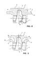
- Figure 4 is a sectional view depicting one manner in which the flange is welded to the top of the piston skirt according to one embodiment of the present invention.
- the peripheral edge 12 of the flange 4 is welded to the top 5 of the skirt 1 using a conventional welding technique.
- Figure 4 depicts the weld seam 15 as being substantially flush with the outer annular surfaces of the flange 4 and the skirt 1.
- Such a configuration can be achieved by providing any necessary gap between the peripheral edge 12 of the flange 4 and the top 5 of the skirt 1 and, after welding, finishing the weld bead so that the seam 15 is smooth.
- the weld seam 15 can be configured so that it does not extend into the cooling gallery 9. Accordingly, there is no apprehension that flashing from the welding process will obstruct the cooling gallery 9 or that the welding process will deposit metal particles in the cooling gallery 9 which could be released during operating of an engine containing the piston.
- Figure 5 is a sectional view depicting one manner in which the flange can be mechanically coupled to the top of the piston skirt according to one embodiment of the present invention.
- the top 5 of the skirt 1 is provided with an annular recess 16 and the peripheral edge 12 of the flange 4 is provided with an annular projection 17 that is configured to be received in the recess 16.
- the recess 16 and projection 17 on the flange 4 are depicted as having circular cross-sectional shapes wherein the narrowest portion of the opening of the recess 16 is less than the diameter of the recess 16 so that the projection 17 can be press-fit into the recess and secured therein.
- the mechanical coupling of the flange 4 to the top 5 of the skirt 1 can be achieved using any cooperating, engaging structures which prevent the flange 4 from separating from the top 5 of the skirt 1, including one or more recesses/projections having various configurations.
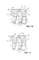
- Figure 6 is a sectional view depicting one manner in which the flange can be mechanically coupled to the top of the piston skirt according to another embodiment of the present invention.
- the peripheral edge 12 of the flange 4 is provided with alterative projections 18 and recesses 19 that engage and interlock with complementarily shaped recesses 20 and projections 21 formed on the top 5 of the skirt 1.
- the mechanical coupling of the flange 4 to the top 5 of the skirt 1 can be achieved using any cooperating, engaging structures which prevent the flange 4 from separating from the top 5 of the skirt 1 and that the invention is not limited to the mechanical coupling structures depicted in Figs. 5 and 6 .
- Figure 7 is a compound cross-sectional view of a piston according to one embodiment of the present invention shown in half section with ring grooves formed in the flange.
- Figure 7 depicts a finished piston that includes a bowl shaped crown 7 and a pair of opposed pin bosses 2 with finished pin bores 10 therein (one shown) and snap ring grooves 23 (one shown).
- Figure 7 also depicts an oil injection port 24 provided in the bottom of cooling gallery 9 into which oil can be injected for cooling the cooling gallery 9 according to known methods.
- the under crown area 25 has been machined away to reduce overall weight of the piston.
- the ring belt 26 (defined by the flange 4) of the piston will be provided with grooves 27 for receiving piston rings including one or more compression rings and an oil ring in a known manner.
- the final piston (shown in Fig. 7 ) is a one-piece steel piston having an internal cooling gallery and a crown and skirt that are formed as an integrated unit.
- the one-piece steel piston of the present invention is made without the use of friction welding and therefore avoids problems and concerns associated with friction welding.
- the process of manufacturing the one-piece steel pistons of the present invention involves forging or casting a pre-machined and pre-metal worked piston or piston blank as shown in Fig.1 that includes a top, a skirt 1, a pair of opposed pin bosses 2 and a flange 4 that extends radially outward from the top.
- the pre-machined and pre-metal worked forged or cast piston or piston blank can be forged or cast with a rough (pre-machined) crown bowl 7 and/or a rough (pre-machined) cooling gallery 9.
- the cooling gallery 9 is provided or otherwise finished by a machining step and an annular abutment 11 is formed at the top 5 of the skirt 1 as shown in Fig. 2 .
- the flange 4 is bent or folded downward so that the peripheral edge 12 of the flange 4 contacts abutment 11 and rests on the top 5 of the skirt 1 as shown in Fig. 3 .
- the flange 4 Prior to bending or folding the flange 4 the flange 4 is machined so that the peripheral edge 12 cooperates with the abutment 11 and is either welded to the top 5 of the skirt 1 or mechanically engages the top 5 portion of the skirt 1.
- the flange 5 is machined so as to have an outer annular surface after bending or folding that is substantially flush with the annular outer surface of the skirt 1 which has also been machined to a finished state. The machining of the annular surfaces of the skirt 1 and flange 4 can be conducted after the flange 4 is bent or folded.
- the pin bore can be provided and/or finished and the under crown area can be machined out as desired to reduce overall weight.
- Figures 1-3 and 7 are directed to embodiments of the present invention in which a flange 4 is provided near the top of the piston blank and subsequently bent or folded downward to close cooling gallery 9.
- the piston blank can be provided with a flange that is bent or folded upward to close a cooling gallery or flanges that are bent or folded downwards and upwards together to close a cooling gallery.
- the flanges could be configured to, after being bent or folded and machined, define portions of the sides or tops of the pistons.
- Figure 8 is a compound cross-sectional view through the pin bore (right hand side) and along the thrust axis (left hand side) of a piston according to another embodiment of the present invention shown in half section before a flange formed on the piston is worked into its final position.
- the piston depicted in Fig. 8 is a steel piston blank that includes a piston skirt 1 opposed pin bosses 2 and a piston head 3.
- a flange 4' extends radially outward from the central portion of the piston head 3 from a location that is midway between the top of the piston and the top of the piston skirt 1.
- the diameter of flange 4' is greater than the diameter of the skirt 1 by an amount that is sufficient to, after any necessary machining, close the cooling gallery as shown in Fig. 10 .
- the flange 4' is configured to be bent or folded under an edge 28 of the top of the piston which is depicted in Fig. 9 .
- the piston head 3 can be forged or cast with a recessed shape 7' or otherwise formed to have a flat top 8.
- a cooling gallery 9 can be partially or completely formed in the forged or cast piston. It is also possible to form rough pin holes 10 during the forging or casting of the piston as indicated in broken lines in Fig. 8 .
- the steel forged or cast piston blank depicted in Fig. 8 can be made using conventional forging or casting techniques that are well known to those skilled in the art.
- Figure 9 is a compound cross-sectional view of a piston according to Fig. 8 shown in half section with a cooling gallery machined into the piston.
- the cooling gallery 9 has been machined to a finished state in the piston.
- an abutment similar to that shown in Fig. 2 can be formed on under edge 28 near the top of the piston if desired. If an abutment is used in this embodiment of the present invention it should have an annular shape that extends circumferentially within the cooling gallery 9 beneath the edge 28 as depicted.
- Figure 10 is a compound cross-sectional view of a piston according to Fig. 9 shown in half section with the flange positioned into its final position.
- the flange 4 has been bent or folded from its position depicted in Figs. 8 and 9 to a position in which the flange 4' closes cooling gallery 9.
- the outer peripheral edge 12' of the flange 4' shown in Figs. 8 and 9 has been displaced by bending or folding the flange 4' so that the peripheral edge 12' is beneath edge 28.
- the flange 4' is configured, e.g. forged or cast and/or machined, so that when the peripheral edge 12' of the flange 4' contacts abutment 11, the annular side surface 13' of the flange 4 (formerly bottom surface) is substantially in alignment with the annular side surface 14 of the skirt 1 so that the overall outer annular surface of the final piston is substantially continuous.
- the peripheral edge 12' of the flange 4' has also been machined in Fig. 10 so as to conform to the configuration of the abutment 11.
- the flange 4' can be bent or folded from its forged position depicted in Fig. 8 to its position depicted in Fig. 10 by bending the flange 4' upwards while spinning the piston about its central axis. During the bending process the flange 4' can be heated. In addition, the bending of the flange 4' can be performed in one or more steps. It is also possible to bend the flange 4' upward using one or more bending forms or any other conventional metal forming process/apparatus.
- the peripheral edge 12' of the flange 4' can be welded to the lower surface of edge 28 according to one embodiment of the present invention using conventional welding techniques.
- the resulting weld seam should be substantially flush with the outer annular surfaces of the flange 4' and the edge 28.
- Such a configuration can be achieved by providing any necessary gap between the peripheral edge 12' of the flange 4' and the lower surface of edge and, after welding, finishing the weld bead so that the seam is smooth.
- the weld seam can be configured so that it does not extend into the cooling gallery 9. Accordingly, there is no apprehension that flashing from the welding process will obstruct the cooling gallery 9 or that the welding process will deposit metal particles in the cooling gallery 9 which could be released during operating of an engine containing the piston.
- the opposing structures can be configured to mechanically interlock using structural configurations similar to those exemplified and discussed in reference to Figs. 5 and 6 above. It is understood that the invention is not limited to the mechanical coupling structures depicted in Figs. 5 and 6 .
- a piston blank with a displaceable flange is not limited to the embodiments of the invention depicted in Figs. 1-3 , 7 and 8-10 .
- the flanges could be positioned and configured to be bent or folded upward or downward and close off different areas of the cooling galleries.
- more than one flange can be used.
- FIGS. 11-14 exemplify other embodiments of the present invention which include different flange configurations.
- Each of Figs. 11-14 depicts pistons in which the respective flanges have been machined and bent or folded into their final positions.
- the flanges extended radially outward from the sides of piston blanks that included features which are generally discussed above.
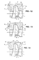
- Figure 11 is a compound cross-sectional view of a piston according to an alternative embodiment of the present invention.
- the flange 4' was originally configured in the piston blank so that when it was bent or folded upward (after being machined to size), a top peripheral edge 29 of the flange 4' abutted a peripheral edge 30 provided or formed adjacent to the top of the piston.
- Figure 12 is a compound cross-sectional view of a piston according to another alternative embodiment of the present invention.
- the flange 4' was originally configured in the piston blank so that when it was bent or folded upward (after being machined to size) the abutting surfaces between the peripheral edge 29 of the flange 4'and the peripheral edge 30 of the top of the piston met along an angle as shown.
- Figure 13 is a compound cross-sectional view of a piston according to another alternative embodiment of the present invention.
- two flanges 4' and 4" were originally provided and configured in the piston blank so that when the upper flange was bent or folded downward and the lower flange was bent or folded upward (after being machined to size) the respective peripheral edges 12' and 12" of the flanges 4' and 4"abutted one another as depicted.
- Figure 14 is a compound cross-sectional view of a piston according to another alternative embodiment of the present invention.
- the flange 4' was originally configured in the piston blank so that when it was bent or folded upward (after being machined to size) the abutting surfaces between the peripheral edge 12' of the flange 4' and the peripheral edge 30 of the top of the piston met over a portion of the cooling gallery 9 as shown.
- cooling gallery can be changed to accommodate the use of different flange configurations.
- the opposing structures can welded together or otherwise be configured to mechanically interlock using structural configurations similar to those exemplified and discussed in reference to Figs. 5 and 6 above or similar configurations.
Landscapes
- Engineering & Computer Science (AREA)
- Mechanical Engineering (AREA)
- Physics & Mathematics (AREA)
- Fluid Mechanics (AREA)
- Chemical & Material Sciences (AREA)
- Combustion & Propulsion (AREA)
- General Engineering & Computer Science (AREA)
- Pistons, Piston Rings, And Cylinders (AREA)
Abstract
A one-piece steel piston that is made from a piston blank that includes a portion that is configured and designed to be displaced to form a cooling gallery and ring belt. The piston blank can be formed by a casting or forging process. The portion that is designed and configured to be displaced is a flange that extends radially outward. The flange is bent downward or upward so that a peripheral edge of the flange contacts another portion of the piston. The peripheral edge of the flange and the other portion of the piston can be welded together or mechanically engaged.
Description
- The present invention relates to piston designs for internal combustion engines. More specifically, the present invention is directed to one-piece steel piston designs and methods of making the same.
- Internal combustion engine pistons are exposed to extremely tough working environments. They are subjected to high temperatures, explosive firing pressures, side forces and inertial forces. As an engine's output is increased more and more, temperatures, cylinder pressures and engine speed can become so high that traditional materials from which pistons are made, including aluminum alloys, reach their fatigue strengths.
- Articulated pistons are two-piece pistons that have a crown made of steel and a skirt made from aluminum. The crown and skirt are joined together by means of a piston pin. In articulated pistons, the crown and skirt are able to articulate so as to move independently of each other.
- Articulated pistons provide several advantages over one-piece cast aluminum pistons. For example, the steel crown in articulated pistons has a thermal expansion rate that is more similar to the thermal expansion rate of iron piston liners than aluminum. In addition, heat from the steel crowns of articulated pistons is not as easily transferred to the aluminum skirt so the skirt retains its shape better. Further, piston secondary motion in articulated pistons can be better than in one-piece pistons.
- Although articulated pistons can withstand relatively higher pressures and temperatures, there are some practical design limitations associated with articulated pistons. For example, articulated pistons require longer piston pins, making the total piston assembly (piston plus piston pin) generally heavier than one-piece aluminum piston assemblies. In addition, since the piston crown and skirt move independently of each other, the skirt cannot effectively function to guide movement of the piston crown. Accordingly, the piston land has to guide movement of the piston crown. This results in land-to-cylinder liner contact which can cause cavitation problems. Another design limitation associated with articulated pistons is that there is no connection between the ring belt and skirt. This allows stresses to be very high in the cooling gallery and on the bowl edge which can cause cracks to occur. Moreover, the lack of connection between the ring belt and skirt and resulting stresses allow for ring groove deformations to be very high which can cause oil consumption, blow-by, and emission problems.
- Piston designers have been trying very hard to come up with new technologies to overcome the problems associated with articulated pistons. A number of proposed solutions have focused on one-piece steel pistons. Unlike articulated pistons, the skirt and crown of one-piece steel pistons form an integrated unit with the piston crown having a cooling gallery. Examples of patented one-piece steel pistons are found in
DE 44 46 726 A1 to Kemnitz ,U.S. Patent No. 6,223,701 to Kruse ,EP 0 992 670 A1 to Gaiser et al. , and International Application Publication No.WO 01/50042 to Gaiser et al. - One of the most challenging aspects of one-piece piston designs is creating a cooling gallery in the piston crown while at the same time ensuring sufficient margins for fatigue strength and minimizing ring groove deformations subject to loads. In
DE 44 46 726 A1 the piston is not connected between ring belt and skirt. Therefore, the overall structure of the piston is not stable and high stress can cause deformation to occur in the piston crown. In addition, because the skirt of the piston is short inDE 44 46 726 A1 , high contact pressures will be created between the skirt and cylinder liner. Moreover, the shortness of the skirt used inDE 44 46 726 A1 limits the ability of the skirt to guide the movement of the piston so that cavitation can occur with respect to the cylinder liner. Overall, the process of manufacturing the one-piece piston ofDE 44 46 726 A1 is very intensive. - In
WO01/50042 A1 - The present invention is directed to one-piece steel pistons that are made from piston blanks that are provided with at least one portion that is configured and designed to be displaced to form a cooling gallery and ring belt.
- According to various features, characteristics and embodiments of the present invention which will become apparent as the description thereof proceeds, the present invention provides a one-piece piston that includes:
- a top;
- a pair of opposed pin bosses with pin bores formed therein;
- a skirt; and
- a cooling gallery that comprises an annular cavity formed in a side of the piston which annular cavity is closed by at least one flange structure which has been displaced so as to close the annular cavity and define a portion of the cooling gallery.
- The present invention further provides a piston blank from which a piston can be fabricated, the piston blank including a top portion, a skirt, a pair of opposed pin bosses and at least one radially extending flange, the at least one radially extending flange being configured to be displaced to contact another portion of the piston.
- The present invention also provides a method of fabricating a one-piece piston which involves:
- providing a piston blank having a top portion, a skirt, a pair of opposed pin bosses and at least one radially extending flange;
- forming an annular cooling gallery in the piston blank; and
- displacing the at least one radially extending flange so as to close off the cooling gallery.
- The present invention further provides a one-piece piston according to the following clauses:
- 1. A one-piece piston that comprises:
- a top;
- a pair of opposed pin bosses with pin bores formed therein;
- a skirt; and
- a cooling gallery that comprises an annular cavity formed in a side of the piston which annular cavity is closed by at least one flange structure which has been displaced so as to close the annular cavity and define a portion of the cooling gallery.
- 2. A one-piece piston according to
clause 1, wherein an abutment is provided in the annular cavity and the at least one flange contacts the abutment. - 3. A one-piece piston according to
clause 1 orclause 2, wherein the at least one flange includes a portion that is welded to or mechanically engaged with another portion of the piston. - 4. A one-piece piston according to any foregoing clause, wherein the piston is made from a steel material.
- 5. A one-piece piston according to any foregoing clause, further comprising a ring belt formed on a portion of the at least one flange.
- 6. A one-piece piston according to any foregoing clause, comprising a plurality of piston ring grooves formed on a portion of the at least one flange.
- 7. A piston blank from which a piston can be fabricated, said piston blank comprising a top portion, a skirt, a pair of opposed pin bosses and at least one radially extending one flange, said at least one radially extending flange being configured to be displaced downward to contact another portion of the piston.
- 8. A piston blank from which a piston can be fabricated according to
clause 7,
wherein one or more of the following is included: a) the piston blank is formed by one of a forging or a casting process; b) the piston blank further comprises an annular cavity; c) the piston blank further comprises pin bores formed in the pin bosses; d) the piston blank further comprises a crown bowl formed in the top portion. - 9. A method of fabricating a one-piece piston which comprises:
- providing a piston blank having a top portion, a skirt, a pair of opposed pin bosses and at least one radially extending flange;
- forming an annular cooling gallery in the piston blank; and
- displacing the at least one radially extending flange so as to close off the cooling gallery.
- 10. A method of fabricating a one-piece piston according to
clause 9, wherein one or more of the following is included: a) the annular cooling gallery is formed by at least in part by a machining process; b) the annular cooling gallery is partially formed in the piston blank and the step of forming the annular cooling gallery comprises machine finishing the annular cooling gallery; c) the piston blank is made by one of a forging or casting process; d) the at least one flange is displaced by bending the at least one flange; e) the method further comprises attaching a portion of the at least one flange to another portion of the piston; f) the step of attaching comprises welding a portion of the at least one flange to the another portion of the piston; g) the step of attaching comprises mechanically engaging a portion of the at least one flange to the another portion of the piston; h) the flange has a diameter that is which greater than the diameter of the skirt; i) the at least one flange is bent upward; j) the at least one flange is bent downward. - The present invention will be described with reference to the attached drawings which are given as non-limiting examples only, in which:
-
Figure 1 is a compound cross-sectional view through the pin bore (right hand side) and along the thrust axis (left hand side) of a piston according to one embodiment of the present invention shown in half section before a flange formed on the piston is worked into its final position. -
Figure 2 is a compound cross-sectional view of a piston according toFig. 1 shown in half section with a cooling gallery machined into the piston and a stop-log formed on the top of the piston skirt. -
Figure 3 is a compound cross-sectional view of a piston according toFig. 1 shown in half section with the flange positioned into its final position. -
Figure 4 is a sectional view depicting one manner in which the flange is welded to the top of the piston skirt according to one embodiment of the present invention. -
Figure 5 is a sectional view depicting one manner in which the flange can be mechanically coupled to the top of the piston skirt according to one embodiment of the present invention. -
Figure 6 is a sectional view depicting one manner in which the flange can be mechanically coupled to the top of the piston skirt according to another embodiment of the present invention. -
Figure 7 is a compound cross-sectional view of a piston according to one embodiment of the present invention shown in half section with ring grooves formed in the flange. -
Figure 8 is a compound cross-sectional view through the pin bore (right hand side) and along the thrust axis (left hand side) of a piston according to another embodiment of the present invention shown in half section before a flange formed on the piston is worked into its final position. -
Figure 9 is a compound cross-sectional view of a piston according toFig. 8 shown in half section with a cooling gallery machined into the piston. -
Figure 10 is a compound cross-sectional view of a piston according toFig. 9 shown in half section with the flange positioned into its final position. -
Figure 11 is a compound cross-sectional view of a piston according to an alternative embodiment of the present invention. -
Figure 12 is a compound cross-sectional view of a piston according to another alternative embodiment of the present invention. -
Figure 13 is a compound cross-sectional view of a piston according to another alternative embodiment of the present invention. -
Figure 14 is a compound cross-sectional view of a piston according to another alternative embodiment of the present invention. - The present invention is directed to one-piece steel pistons for internal combustion engines. The one-piece steel pistons of the present invention are formed from single unitary steel forged or cast parts which are subsequently subjected to machining and metal working processes. The one-piece steel pistons include cooling galleries which may be partially formed during the forging or casting process and which are otherwise completely formed after the subsequent machining and metal working. The pre-machined, pre-metal-worked forged or cast parts are referred to herein as "piston blanks." According to the present invention the piston blanks each include at least one portion that is configured to be displaced during metal working so as to define the final structure of the one-piece pistons. The forged or cast parts from which the one-piece steel pistons are produced can also be provided with and/or machined to have abutment portions which assist in properly positioning the displaced portions as they are displaced. The displaced portions can be welded to, or configured to mechanically interlock with, an adjacent portion of the piston.
- The process of manufacturing the one-piece steel pistons of the present invention involves forging or casting a pre-machined and pre-metal worked piston or piston blank that includes a top portion, a skirt, a pair of opposed pin bosses, and one or more flanges that extend radially outward from the top and/or a side portion of the piston blank. Optionally, the pre-machined and pre-metal-worked piston blank can be forged or cast with a rough (pre-finished) crown bowl and/or a rough (pre-finished) cooling gallery and/or rough (pre-finished) pin bores. In the next step the cooling gallery is provided or finished by a machining step and an annular abutment (when used) is formed at an appropriate location to assist in properly positioning the displaced portions as they are displaced. Next, the flange(s) is/are bent or folded downward and/or upward so that the peripheral edge of the flange(s) abutments an adjacent portion of the piston. Prior to bending or folding the flange(s), the flange(s) is/are machined so that the peripheral edge of the flange(s) is/are dimensioned and configured to cooperate with an adjacent portion of the piston to either mechanically engage or to be welded to the adjacent portion of the piston. After the flange(s) is/are bent or folded into position, grooves for compression rings and an oil ring are formed in a portion of the flange(s) that defines the ring belt in the finished piston. At any convenient time during the above steps, the pin bores may be provided and/or finished and the under crown area can be machined out as desired to reduce overall weight.
- The one-piece steel pistons of the present invention can be made from any suitable steel material that can be worked as described herein and that is capable of withstanding the high combustion pressures, high piston speeds, high temperatures and mechanical stresses that are common in the environment of internal combustion engines. Various known types of carbon steel materials are suitable for purposes of the present invention. The piston blank can be made by a forging or casting process.
- Reference will hereafter be made to the attached drawings in which common reference numbers are used throughout the various figures to identify similar elements when possible.
-
Figure 1 is a compound cross-sectional view through the pin bore (right hand side) and along the thrust axis (left hand side) of a piston according to one embodiment of the present invention shown in half section before the T-form flange is worked into its final position. The piston depicted inFig. 1 is a steel piston blank that includes apiston skirt 1opposed pin bosses 2 and a piston head 3. Aflange 4 extends radially outward from the central portion of the piston head 3 near the top. As indicted inFig. 1 , the diameter, DT, offlange 4 is greater than the diameter, DK, of theskirt 1. The diameter, DT, of theflange 4 is greater than the diameter, DK, of theskirt 1 by an amount that is equal to or greater than the difference in height between the top of the piston and thetop 5 of theskirt 1. Theflange 4 is referred to herein as a T-fold flange due to its cross-sectional shape in relationship to the piston head 3 and the manner in which theflange 4 is folded or bent by machining as discussed in detail below to form the final one-piece steel piston. - As indicated in broken lines, the piston head 3 can be forged or cast with a
crown shape 7 or otherwise formed to have aflat top 8. In addition, as indicated in broken lines, acooling gallery 9 can be partially or completely formed in the forged or cast piston blank. It is also possible to form rough pin holes 10 during the forging or casting of the piston as indicated in broken lines inFig. 1 . Although the design of the one-piece steel piston of the present invention is novel, the steel forged or cast piston blank depicted inFig. 1 can be made using conventional forging or casting techniques that are well known to those skilled in the art. - An alternative to forming a
crown shape 7 in the forged or cast piston blank and/or forming acooling gallery 9 in the forged or cast piston blank and/or forming a pin bore 10 in the forged or cast piston blank would be to machine one or more of these features in the forged or cast piston blank. However, forming these features in the forged or cast piston blank would reduce machining and material costs. -
Figure 2 is a compound cross-sectional view of a piston according toFig. 1 shown in half section with the cooling gallery machined to include a stop-log on the top of the piston skirt. In the embodiment of the piston depicted inFig. 2 thecooling gallery 9 has been machined to a finished state in the piston. In addition, anabutment 11 has been formed on thetop 5 of theskirt 1. Theabutment 11 also referred to as a stop-log has an annular shape that extends circumferentially within thecooling gallery 9 along thetop 5 of theskirt 1. -
Figure 3 is a compound cross-sectional view of a piston according toFig 1 shown in half section with the T-form flange positioned into its final position. InFig. 3 theflange 4 has been bent or folded from its position depicted inFigs. 1 and 2 to a position in which theflange 4closes cooling gallery 9. As shown inFig. 3 , the outerperipheral edge 12 of theflange 4 shown inFigs. 1 and 2 has been displaced by bending or folding theflange 4 so that theperipheral edge 12contacts abutment 11 and rests ontop 5 of theskirt 1. - From
Fig. 3 it can be seen that theflange 4 is configured, e.g. forged or cast and/or machined, so that when theperipheral edge 12 of theflange 4contacts abutment 11, theannular side surface 13 of the flange 4 (formerly top surface) is substantially in alignment with the annular side surface 14 of theskirt 1 so that the overall outer annular surface of the final piston is substantially continuous. Theperipheral edge 12 of theflange 4 has also been machined inFig. 3 so as to conform to the configuration of theabutment 11. - The
flange 4 can be bent or folded from its forged position depicted inFig. 1 to its position depicted inFig. 3 by bending theflange 4 downwards towards theskirt 1 while spinning the piston about its central axis. During the bending process theflange 4 can be heated. In addition, the bending of theflange 4 can be performed in one or more steps. It is also possible to bend theflange 4 toward theskirt 1 using one or more bending forms or any other conventional metal forming processes/apparatus. -
Figure 4 is a sectional view depicting one manner in which the flange is welded to the top of the piston skirt according to one embodiment of the present invention. InFig. 4 theperipheral edge 12 of theflange 4 is welded to thetop 5 of theskirt 1 using a conventional welding technique.Figure 4 depicts theweld seam 15 as being substantially flush with the outer annular surfaces of theflange 4 and theskirt 1. Such a configuration can be achieved by providing any necessary gap between theperipheral edge 12 of theflange 4 and thetop 5 of theskirt 1 and, after welding, finishing the weld bead so that theseam 15 is smooth. It is noted that theweld seam 15 can be configured so that it does not extend into thecooling gallery 9. Accordingly, there is no apprehension that flashing from the welding process will obstruct thecooling gallery 9 or that the welding process will deposit metal particles in thecooling gallery 9 which could be released during operating of an engine containing the piston. -
Figure 5 is a sectional view depicting one manner in which the flange can be mechanically coupled to the top of the piston skirt according to one embodiment of the present invention. In the embodiment of the invention depicted inFig. 5 , thetop 5 of theskirt 1 is provided with anannular recess 16 and theperipheral edge 12 of theflange 4 is provided with anannular projection 17 that is configured to be received in therecess 16. Therecess 16 andprojection 17 on theflange 4 are depicted as having circular cross-sectional shapes wherein the narrowest portion of the opening of therecess 16 is less than the diameter of therecess 16 so that theprojection 17 can be press-fit into the recess and secured therein. In alternative embodiments of the present invention the mechanical coupling of theflange 4 to thetop 5 of theskirt 1 can be achieved using any cooperating, engaging structures which prevent theflange 4 from separating from thetop 5 of theskirt 1, including one or more recesses/projections having various configurations. -
Figure 6 is a sectional view depicting one manner in which the flange can be mechanically coupled to the top of the piston skirt according to another embodiment of the present invention. In the embodiment of the invention depicted inFig. 6 theperipheral edge 12 of theflange 4 is provided withalterative projections 18 and recesses 19 that engage and interlock with complementarily shapedrecesses 20 andprojections 21 formed on thetop 5 of theskirt 1. FromFigs 5 and 6 it can be understood that the mechanical coupling of theflange 4 to thetop 5 of theskirt 1 can be achieved using any cooperating, engaging structures which prevent theflange 4 from separating from thetop 5 of theskirt 1 and that the invention is not limited to the mechanical coupling structures depicted inFigs. 5 and 6 . -
Figure 7 is a compound cross-sectional view of a piston according to one embodiment of the present invention shown in half section with ring grooves formed in the flange.Figure 7 depicts a finished piston that includes a bowl shapedcrown 7 and a pair ofopposed pin bosses 2 with finished pin bores 10 therein (one shown) and snap ring grooves 23 (one shown).Figure 7 also depicts anoil injection port 24 provided in the bottom of coolinggallery 9 into which oil can be injected for cooling thecooling gallery 9 according to known methods. In the piston shown inFig. 7 the under crown area 25 has been machined away to reduce overall weight of the piston. - In one of the final manufacturing steps, the ring belt 26 (defined by the flange 4) of the piston will be provided with
grooves 27 for receiving piston rings including one or more compression rings and an oil ring in a known manner. - As can be appreciated, the final piston (shown in
Fig. 7 ) is a one-piece steel piston having an internal cooling gallery and a crown and skirt that are formed as an integrated unit. The one-piece steel piston of the present invention is made without the use of friction welding and therefore avoids problems and concerns associated with friction welding. - The process of manufacturing the one-piece steel pistons of the present invention involves forging or casting a pre-machined and pre-metal worked piston or piston blank as shown in
Fig.1 that includes a top, askirt 1, a pair ofopposed pin bosses 2 and aflange 4 that extends radially outward from the top. Optionally, the pre-machined and pre-metal worked forged or cast piston or piston blank can be forged or cast with a rough (pre-machined)crown bowl 7 and/or a rough (pre-machined) coolinggallery 9. - In the next step the cooling
gallery 9 is provided or otherwise finished by a machining step and anannular abutment 11 is formed at thetop 5 of theskirt 1 as shown inFig. 2 . - Next, the
flange 4 is bent or folded downward so that theperipheral edge 12 of theflange 4contacts abutment 11 and rests on thetop 5 of theskirt 1 as shown inFig. 3 . Prior to bending or folding theflange 4 theflange 4 is machined so that theperipheral edge 12 cooperates with theabutment 11 and is either welded to thetop 5 of theskirt 1 or mechanically engages the top 5 portion of theskirt 1. In addition, theflange 5 is machined so as to have an outer annular surface after bending or folding that is substantially flush with the annular outer surface of theskirt 1 which has also been machined to a finished state. The machining of the annular surfaces of theskirt 1 andflange 4 can be conducted after theflange 4 is bent or folded. - After the
flange 4 is bent or foldedgrooves 27 for compression rings and an oil ring are formed in a portion of theflange 4 that defines thering belt 26. - At any convenient time during the above steps, the pin bore can be provided and/or finished and the under crown area can be machined out as desired to reduce overall weight.
-
Figures 1-3 and7 are directed to embodiments of the present invention in which aflange 4 is provided near the top of the piston blank and subsequently bent or folded downward to closecooling gallery 9. - In further embodiments of the present invention the piston blank can be provided with a flange that is bent or folded upward to close a cooling gallery or flanges that are bent or folded downwards and upwards together to close a cooling gallery. In addition to closing the cooling galleries, the flanges could be configured to, after being bent or folded and machined, define portions of the sides or tops of the pistons.
-
Figure 8 is a compound cross-sectional view through the pin bore (right hand side) and along the thrust axis (left hand side) of a piston according to another embodiment of the present invention shown in half section before a flange formed on the piston is worked into its final position. - The piston depicted in
Fig. 8 is a steel piston blank that includes apiston skirt 1opposed pin bosses 2 and a piston head 3. A flange 4' extends radially outward from the central portion of the piston head 3 from a location that is midway between the top of the piston and the top of thepiston skirt 1. The diameter of flange 4' is greater than the diameter of theskirt 1 by an amount that is sufficient to, after any necessary machining, close the cooling gallery as shown inFig. 10 . In the embodiment of the invention depicted inFigs. 8-10 , the flange 4' is configured to be bent or folded under anedge 28 of the top of the piston which is depicted inFig. 9 . - As indicated in broken lines, the piston head 3 can be forged or cast with a recessed shape 7' or otherwise formed to have a
flat top 8. In addition, as indicated in broken lines, acooling gallery 9 can be partially or completely formed in the forged or cast piston. It is also possible to form rough pin holes 10 during the forging or casting of the piston as indicated in broken lines inFig. 8 . The steel forged or cast piston blank depicted inFig. 8 can be made using conventional forging or casting techniques that are well known to those skilled in the art. - An alternative to forming a crown shape 7' in the forged or cast piston blank and/or forming a
cooling gallery 9 in the forged or cast piston blank and/or forming a pin bore 10 in the forged or cast piston blank would be to machine one or more of these features in the forged or cast piston blank. However, forming these features in the forged or cast piston blank would reduce machining and material costs. -
Figure 9 is a compound cross-sectional view of a piston according toFig. 8 shown in half section with a cooling gallery machined into the piston. In the embodiment of the piston depicted inFig. 9 , thecooling gallery 9 has been machined to a finished state in the piston. In addition, an abutment similar to that shown inFig. 2 can be formed on underedge 28 near the top of the piston if desired. If an abutment is used in this embodiment of the present invention it should have an annular shape that extends circumferentially within thecooling gallery 9 beneath theedge 28 as depicted. It is to be understood that while the abutment structures discussed herein are useful in assisting in the proper positioning and alignment of the flanges when they are displaced, it is possible to eliminate the abutments as long as more care is taken to bend of fold the flanges into their correct portions. -
Figure 10 is a compound cross-sectional view of a piston according toFig. 9 shown in half section with the flange positioned into its final position. InFig. 10 theflange 4 has been bent or folded from its position depicted inFigs. 8 and 9 to a position in which the flange 4'closes cooling gallery 9. As shown inFig. 10 , the outer peripheral edge 12' of the flange 4' shown inFigs. 8 and 9 has been displaced by bending or folding the flange 4' so that the peripheral edge 12' is beneathedge 28. - From
Fig. 10 it can be seen that the flange 4' is configured, e.g. forged or cast and/or machined, so that when the peripheral edge 12' of the flange 4'contacts abutment 11, the annular side surface 13' of the flange 4 (formerly bottom surface) is substantially in alignment with the annular side surface 14 of theskirt 1 so that the overall outer annular surface of the final piston is substantially continuous. The peripheral edge 12' of the flange 4' has also been machined inFig. 10 so as to conform to the configuration of theabutment 11. - The flange 4' can be bent or folded from its forged position depicted in
Fig. 8 to its position depicted inFig. 10 by bending the flange 4' upwards while spinning the piston about its central axis. During the bending process the flange 4' can be heated. In addition, the bending of the flange 4' can be performed in one or more steps. It is also possible to bend the flange 4' upward using one or more bending forms or any other conventional metal forming process/apparatus. - The peripheral edge 12' of the flange 4' can be welded to the lower surface of
edge 28 according to one embodiment of the present invention using conventional welding techniques. In such a case the resulting weld seam should be substantially flush with the outer annular surfaces of the flange 4' and theedge 28. Such a configuration can be achieved by providing any necessary gap between the peripheral edge 12' of the flange 4' and the lower surface of edge and, after welding, finishing the weld bead so that the seam is smooth. It is noted that the weld seam can be configured so that it does not extend into thecooling gallery 9. Accordingly, there is no apprehension that flashing from the welding process will obstruct thecooling gallery 9 or that the welding process will deposit metal particles in thecooling gallery 9 which could be released during operating of an engine containing the piston. - As an alternative to welding peripheral edge 12' of the flange 4' flange to the lower surface of
edge 28 the opposing structures can be configured to mechanically interlock using structural configurations similar to those exemplified and discussed in reference toFigs. 5 and 6 above. It is understood that the invention is not limited to the mechanical coupling structures depicted inFigs. 5 and 6 . - The concept of providing a piston blank with a displaceable flange is not limited to the embodiments of the invention depicted in
Figs. 1-3 ,7 and8-10 . In other embodiments the flanges could be positioned and configured to be bent or folded upward or downward and close off different areas of the cooling galleries. In other embodiments more than one flange can be used. -
Figures 11-14 exemplify other embodiments of the present invention which include different flange configurations. Each ofFigs. 11-14 depicts pistons in which the respective flanges have been machined and bent or folded into their final positions. However, it is readily understood that before being machined and bent or folded the flanges extended radially outward from the sides of piston blanks that included features which are generally discussed above. -
Figure 11 is a compound cross-sectional view of a piston according to an alternative embodiment of the present invention. InFig. 11 , the flange 4' was originally configured in the piston blank so that when it was bent or folded upward (after being machined to size), a topperipheral edge 29 of the flange 4' abutted aperipheral edge 30 provided or formed adjacent to the top of the piston. -
Figure 12 is a compound cross-sectional view of a piston according to another alternative embodiment of the present invention. InFig. 12 , the flange 4' was originally configured in the piston blank so that when it was bent or folded upward (after being machined to size) the abutting surfaces between theperipheral edge 29 of the flange 4'and theperipheral edge 30 of the top of the piston met along an angle as shown. -
Figure 13 is a compound cross-sectional view of a piston according to another alternative embodiment of the present invention. InFig. 13 , twoflanges 4' and 4" were originally provided and configured in the piston blank so that when the upper flange was bent or folded downward and the lower flange was bent or folded upward (after being machined to size) the respectiveperipheral edges 12' and 12" of theflanges 4' and 4"abutted one another as depicted. -
Figure 14 is a compound cross-sectional view of a piston according to another alternative embodiment of the present invention. InFig. 14 , the flange 4' was originally configured in the piston blank so that when it was bent or folded upward (after being machined to size) the abutting surfaces between the peripheral edge 12' of the flange 4' and theperipheral edge 30 of the top of the piston met over a portion of thecooling gallery 9 as shown. - It is noted that the shape of the cooling gallery can be changed to accommodate the use of different flange configurations.
- In each of the embodiments depicted in
Figs. 11-14 and in other further embodiments of the present invention that are based upon the general concepts exemplified, the opposing structures can welded together or otherwise be configured to mechanically interlock using structural configurations similar to those exemplified and discussed in reference toFigs. 5 and 6 above or similar configurations. - Although the present invention has been described with reference to particular means, materials and embodiments, from the foregoing description one skilled in the art can easily ascertain the essential characteristics of the present invention and various changes and modifications can be made to adapt the various uses and characteristics without departing from the spirit and scope of the present invention as described above and set forth in the attached claims.
Claims (12)
- A one-piece piston that comprises:a top;a pair of opposed pin bosses with pin bores formed therein;a skirt; anda cooling gallery that comprises an annular cavity formed in a side of the piston which annular cavity is closed by at least one flange structure which has been displaced so as to close the annular cavity and define a portion of the cooling gallery;wherein the at least one flange structure includes a portion which is attached to another portion of the piston.
- A one-piece piston according to claim 1, wherein the portion is mechanically engaged or coupled with said another portion of the piston.
- A one-piece piston according to claim 2 including a coupling structure arranged to prevent the at least one flange structure from separating from said another portion.
- A one-piece piston according to claim 2 or claim 3 wherein the portion is provided with an annular projection that is configured to be received in an annular recess in said another portion.
- A one-piece piston according to claim 2 or claim 3 wherein the portion is provided with projections and recesses that engage and interlock with complementary recesses and projections on said another portion.
- A one-piece piston according to claim 1 wherein the portion is welded to said another portion.
- A piston blank from which a piston can be fabricated, said piston blank comprising a top portion, a skirt, a pair of opposed pin bosses and at least one radially extending one flange, said at least one radially extending flange being configured to be displaced downward to contact another portion of the piston, and to be attached to another portion of the piston.
- A piston blank from which a piston can be fabricated according to clause 7,
wherein one or more of the following is included: a) the piston blank is formed by one of a forging or a casting process; b) the piston blank further comprises an annular cavity; c) the piston blank further comprises pin bores formed in the pin bosses; d) the piston blank further comprises a crown bowl formed in the top portion. - A method of fabricating a one-piece piston which comprises:providing a piston blank having a top portion, a skirt, a pair of opposed pin bosses and at least one radially extending flange;forming an annular cooling gallery in the piston blank;displacing the at least one radially extending flange so as to close off the cooling gallery;
andattaching a portion of the flange to another portion of the piston. - A method of fabricating a one-piece piston according to claim 9, wherein the step of attaching comprises mechanically engaging the flange with said another portion of the piston.
- A method of fabricating a one-piece piston according to claim 9, wherein the step of attaching comprises welding a portion of the flange to said another portion of the piston.
- A method of fabricating a one-piece piston according to any of claims 9 to 11,
wherein one or more of the following is included: a) the annular cooling gallery is formed by at least in part by a machining process; b) the annular cooling gallery is partially formed in the piston blank and the step of forming the annular cooling gallery comprises machine finishing the annular cooling gallery; c) the piston blank is made by one of a forging or casting process; d) the at least one flange is displaced by bending the at least one flange; e) the flange has a diameter that is which greater than the diameter of the skirt; f) the at least one flange is bent upward; g) the at least one flange is bent downward.
Applications Claiming Priority (2)
| Application Number | Priority Date | Filing Date | Title |
|---|---|---|---|
| US10/885,810 US7104183B2 (en) | 2004-07-07 | 2004-07-07 | One-piece steel piston |
| EP05254279.2A EP1614885B1 (en) | 2004-07-07 | 2005-07-07 | One-piece steel piston |
Related Parent Applications (2)
| Application Number | Title | Priority Date | Filing Date |
|---|---|---|---|
| EP05254279.2A Division-Into EP1614885B1 (en) | 2004-07-07 | 2005-07-07 | One-piece steel piston |
| EP05254279.2A Division EP1614885B1 (en) | 2004-07-07 | 2005-07-07 | One-piece steel piston |
Publications (1)
| Publication Number | Publication Date |
|---|---|
| EP2492483A2 true EP2492483A2 (en) | 2012-08-29 |
Family
ID=34982384
Family Applications (3)
| Application Number | Title | Priority Date | Filing Date |
|---|---|---|---|
| EP12163657A Withdrawn EP2511506A2 (en) | 2004-07-07 | 2005-07-07 | One-piece steel piston |
| EP12163658A Withdrawn EP2492483A2 (en) | 2004-07-07 | 2005-07-07 | One-piece steel piston |
| EP05254279.2A Expired - Lifetime EP1614885B1 (en) | 2004-07-07 | 2005-07-07 | One-piece steel piston |
Family Applications Before (1)
| Application Number | Title | Priority Date | Filing Date |
|---|---|---|---|
| EP12163657A Withdrawn EP2511506A2 (en) | 2004-07-07 | 2005-07-07 | One-piece steel piston |
Family Applications After (1)
| Application Number | Title | Priority Date | Filing Date |
|---|---|---|---|
| EP05254279.2A Expired - Lifetime EP1614885B1 (en) | 2004-07-07 | 2005-07-07 | One-piece steel piston |
Country Status (4)
| Country | Link |
|---|---|
| US (2) | US7104183B2 (en) |
| EP (3) | EP2511506A2 (en) |
| JP (1) | JP5008278B2 (en) |
| CN (2) | CN110107425B (en) |
Families Citing this family (43)
| Publication number | Priority date | Publication date | Assignee | Title |
|---|---|---|---|---|
| EP1452250B1 (en) * | 2003-03-01 | 2008-11-12 | KS Kolbenschmidt GmbH | Method of manufacturing a cooling duct piston with deformable flange |
| JP4253644B2 (en) * | 2004-06-28 | 2009-04-15 | 理研鍛造株式会社 | Manufacturing method of piston for internal combustion engine |
| US7104183B2 (en) * | 2004-07-07 | 2006-09-12 | Karl Schmidt Unisia, Inc. | One-piece steel piston |
| WO2006063608A1 (en) * | 2004-12-16 | 2006-06-22 | Cdp Bharat Forge Gmbh | Method for producing rotationally symmetrical, undercut contours |
| DE102005041000B4 (en) * | 2005-08-29 | 2012-07-05 | Thyssenkrupp Automotive Ag | Method, production line and piston blank for producing a one-piece piston for internal combustion engines, and pistons for internal combustion engines |
| DE502005009435D1 (en) | 2005-09-17 | 2010-05-27 | Ks Kolbenschmidt Gmbh | PISTONS, IN PARTICULAR COLD-CHANNEL PISTON, WITH THREE FRICTION WELDING ZONES |
| EP1984613B1 (en) * | 2006-02-17 | 2017-11-01 | KS Kolbenschmidt GmbH | Multiple-part steel piston for an internal combustion engine having a cooling duct |
| DE102007013183A1 (en) * | 2006-07-07 | 2008-01-17 | Ks Kolbenschmidt Gmbh | Cooling channel piston for an internal combustion engine |
| US7578229B2 (en) * | 2006-12-01 | 2009-08-25 | Karl Schmidt Unisia, Inc. | Piston produced from a single forged or cast piston blank |
| ATE502200T1 (en) * | 2007-08-24 | 2011-04-15 | Thyssenkrupp Metalurgica Campo Limpo Ltda | PISTON FOR AN INTERNAL COMBUSTION ENGINE AND METHOD FOR PRODUCING SUCH A PISTON |
| JP4510061B2 (en) * | 2007-09-18 | 2010-07-21 | 理研鍛造株式会社 | Manufacturing method of piston for internal combustion engine |
| DE102008045456A1 (en) * | 2008-09-02 | 2010-03-04 | Mahle International Gmbh | Piston for an internal combustion engine |
| DE102009056917B4 (en) * | 2009-12-03 | 2018-12-20 | Mahle International Gmbh | Method for producing a piston for an internal combustion engine |
| PL2595771T3 (en) * | 2010-07-19 | 2017-07-31 | Ks Kolbenschmidt Gmbh | Method for producing a cooling channel system for internal combustion engines and piston produced in this way |
| US9856820B2 (en) | 2010-10-05 | 2018-01-02 | Mahle International Gmbh | Piston assembly |
| DE102011078145A1 (en) * | 2011-06-27 | 2012-12-27 | Mahle International Gmbh | Forging method for producing a piston or piston skirt |
| US8973484B2 (en) | 2011-07-01 | 2015-03-10 | Mahle Industries Inc. | Piston with cooling gallery |
| BRPI1103314A2 (en) | 2011-07-21 | 2013-08-06 | Whirlpool Sa | linear compressor |
| CN102407431B (en) * | 2011-11-02 | 2013-08-14 | 山东滨州渤海活塞股份有限公司 | Technology for manufacturing hotly-spun pressed forged steel single-piece piston with inner cooling oil cavity |
| KR101999569B1 (en) | 2011-12-08 | 2019-07-15 | 테네코 인코퍼레이티드 | Onepiece piston with improved combustion bowl rim region and method of manufacture |
| DE102013201927A1 (en) * | 2012-02-06 | 2013-08-08 | Ks Kolbenschmidt Gmbh | Fully produced by forging piston blank of a cooling channel piston |
| KR102068372B1 (en) | 2012-03-12 | 2020-01-20 | 테네코 인코퍼레이티드 | Engine piston |
| DE102013208557A1 (en) * | 2012-05-11 | 2013-11-14 | Ks Kolbenschmidt Gmbh | Method for producing a cooling channel piston |
| JP5949148B2 (en) * | 2012-05-23 | 2016-07-06 | 日産自動車株式会社 | Multi-link internal combustion engine |
| KR20150056622A (en) * | 2012-09-18 | 2015-05-26 | 페더럴-모걸 코오포레이숀 | Steel piston with counter-bore design |
| CN104797803B (en) | 2012-09-27 | 2018-02-02 | 费德罗-莫格尔公司 | The piston and piston assembly and its building method that compression height reduces |
| DE102013218709A1 (en) * | 2012-09-27 | 2014-03-27 | Ks Kolbenschmidt Gmbh | Two-piece constructed piston of an internal combustion engine |
| CN105143732A (en) * | 2013-01-29 | 2015-12-09 | 马勒国际有限公司 | Steel piston with fourth land guidance and improved friction characteristics |
| JP6401188B2 (en) * | 2013-02-18 | 2018-10-03 | フェデラル−モーグル・リミテッド・ライアビリティ・カンパニーFederal−Mogul Llc | Complex shaped piston oil gallery with piston crown made by cast metal or powder metal process |
| US10787991B2 (en) | 2013-02-18 | 2020-09-29 | Tenneco Inc. | Complex-shaped forged piston oil galleries |
| US9334958B2 (en) * | 2013-02-18 | 2016-05-10 | Federal-Mogul Corporation | Complex-shaped forged piston oil galleries |
| EP2958703A1 (en) * | 2013-02-22 | 2015-12-30 | Mahle International GmbH | Piston assembly with weld support |
| DE102013014346A1 (en) * | 2013-03-18 | 2014-10-02 | Mahle International Gmbh | Method for producing a piston for an internal combustion engine and piston produced by means of this method |
| CN104827242B (en) * | 2014-02-10 | 2017-11-10 | 廖树汉 | Interior casting forging and stamping make the machining process of workpiece subduction car plane milling boring after surface layer shaping |
| US20160305365A1 (en) * | 2015-04-20 | 2016-10-20 | Federal-Mogul Corporation | Piston with complex shaped combustion bowl and cooling gallery and method of construction thereof |
| WO2016179062A1 (en) | 2015-05-01 | 2016-11-10 | Ohio State Innovation Foundation | Hot forming of cooling galleries in steel pistons |
| US10253722B2 (en) | 2015-05-01 | 2019-04-09 | Ks Kolbenschmidt Us, Inc. | Methods for forging a piston blank |
| DE102016114954A1 (en) * | 2015-08-11 | 2017-02-16 | Ks Kolbenschmidt Gmbh | Process for making a monoblock piston and monoblock pistons |
| CN105041501B (en) * | 2015-09-02 | 2018-02-09 | 湖南江滨机器(集团)有限责任公司 | Diesel engine and piston |
| EP3371443B1 (en) * | 2015-11-02 | 2024-04-10 | KS Kolbenschmidt GmbH | Optimized hub support |
| US10422299B2 (en) | 2016-04-21 | 2019-09-24 | Tenneco Inc. | Piston with asymmetric upper combustion surface and method of manufacture thereof |
| EP3452712B1 (en) | 2016-05-04 | 2024-11-20 | KS Kolbenschmidt GmbH | Piston |
| CN108561237B (en) * | 2018-05-24 | 2024-05-14 | 华域科尔本施密特活塞有限公司 | Gasoline engine aluminum piston valve pit and flash processing technology thereof |
Citations (4)
| Publication number | Priority date | Publication date | Assignee | Title |
|---|---|---|---|---|
| DE4446726A1 (en) | 1994-12-24 | 1996-06-27 | Mahle Gmbh | Process for producing a one-piece cooling channel piston |
| EP0992670A2 (en) | 1998-10-06 | 2000-04-12 | Caterpillar Inc. | Method and apparatus for making a two piece unitary piston |
| US6223701B1 (en) | 1999-08-16 | 2001-05-01 | Caterpillar Inc. | Cooled one piece piston and method |
| WO2001050042A1 (en) | 1999-12-30 | 2001-07-12 | Federal-Mogul Corporation | Piston having uncoupled skirt |
Family Cites Families (34)
| Publication number | Priority date | Publication date | Assignee | Title |
|---|---|---|---|---|
| US1835863A (en) * | 1928-08-06 | 1931-12-08 | Champion Machine & Forging Com | Method of forming pistons |
| US2244008A (en) * | 1939-06-16 | 1941-06-03 | Gen Motors Corp | Piston construction |
| CH230566A (en) | 1942-03-24 | 1944-01-15 | Mahle Kg | Process for the production of forged pistons for internal combustion engines. |
| DE926169C (en) | 1944-01-22 | 1955-04-07 | Bayerische Motoren Werke Ag | Pistons for internal combustion engines, especially aircraft engines |
| DE1103698B (en) * | 1959-10-23 | 1961-03-30 | Schmidt Gmbh Karl | Pistons manufactured by forging or pressing, preferably made of an aluminum alloy for internal combustion engines and compressors |
| DE1210302B (en) * | 1959-12-02 | 1966-02-03 | Karl Schmidt Ges Mit Beschraen | Method of manufacturing pistons with a coolant space in the piston crown |
| US3341924A (en) * | 1963-12-02 | 1967-09-19 | Trw Inc | Method of making a forged piston with an oil gallery |
| GB1092720A (en) | 1966-07-07 | 1967-11-29 | Trw Inc | Improvements in or relating to methods of manufacturing pistons and pistons formed thereby |
| FR2575227B1 (en) * | 1984-12-20 | 1988-12-23 | Semt | PISTON WITH LIGHT STRUCTURE, PARTICULARLY FOR AN INTERNAL COMBUSTION ENGINE |
| DE3502249A1 (en) * | 1985-01-24 | 1986-07-24 | Berchem & Schaberg Gmbh, 4650 Gelsenkirchen | Process for the formation of a recess chamber in the production of shaped parts with the aid of a die-forging press |
| DE3502248C1 (en) | 1985-01-24 | 1986-05-07 | Berchem & Schaberg Gmbh, 4650 Gelsenkirchen | Method of manufacturing a one-piece piston for an internal combustion engine by forging |
| US4683809A (en) * | 1985-05-02 | 1987-08-04 | The United States Of America As Represented By The Administrator Of The National Aeronautics And Space Administration | Lightweight piston |
| DE3713241A1 (en) * | 1986-12-24 | 1988-07-07 | Mahle Gmbh | AS A ROUGH MOLDED HEAD OF A TWO-PIECE PISTON |
| BR8803970A (en) * | 1988-07-15 | 1990-03-20 | Metal Leve Sa | REFRIGERATED ARTICULATED PUMP |
| US4909133A (en) * | 1988-09-28 | 1990-03-20 | The United States Of America As Represented By The Administrator Of The National Aeronautics And Space Administration | Lightweight piston architecture |
| US4867119A (en) | 1988-10-21 | 1989-09-19 | Caterpillar Inc. | Engine piston assembly and forged piston member therefor having a cooling recess |
| DE4034467A1 (en) * | 1990-10-30 | 1992-05-07 | Freudenberg Carl Fa | GASKET ARRANGEMENT FOR USE IN THE FUEL CONNECTOR OF A FUEL TANK |
| JP3173060B2 (en) * | 1991-09-30 | 2001-06-04 | アイシン精機株式会社 | Method of manufacturing piston for internal combustion engine |
| JPH06346787A (en) * | 1993-06-10 | 1994-12-20 | Toyota Motor Corp | Piston for internal combustion engine |
| US5900193A (en) * | 1996-03-06 | 1999-05-04 | The United States Of America As Represented By The Administrator Of The National Aeronautics And Space Administration | Carbon-carbon piston architectures |
| GB9605838D0 (en) * | 1996-03-20 | 1996-05-22 | Perkins Ltd | A method for producing a piston for an internal combustion engine and a piston produced by the method |
| JP3189684B2 (en) * | 1996-06-04 | 2001-07-16 | トヨタ自動車株式会社 | Piston casting method |
| BR9601835A (en) * | 1996-06-14 | 1998-09-29 | Metal Leve Sa | Internal combustion engine piston |
| US5839352A (en) * | 1996-08-07 | 1998-11-24 | Cummins Engine Company, Inc. | Articulated piston |
| DE19747944A1 (en) * | 1997-10-30 | 1999-05-06 | Mahle Gmbh | Piston with a central cold room |
| US6112642A (en) * | 1998-10-06 | 2000-09-05 | Caterpillar Inc. | Method and apparatus for making a two piece unitary piston |
| DE19846152A1 (en) | 1998-10-07 | 2000-04-13 | Mahle Gmbh | Piston with piston base made of forged steel and a cooling channel |
| DE19922809A1 (en) * | 1999-05-19 | 2000-11-23 | Mahle Gmbh | Casting process used in the production of pistons comprises producing recesses by cores that move on deformation |
| US6862976B2 (en) * | 2001-10-23 | 2005-03-08 | Federal-Mogul World Wide, Inc. | Monobloc piston |
| DE10244510A1 (en) | 2002-09-25 | 2004-04-08 | Mahle Gmbh | One-piece cooling channel piston for an internal combustion engine |
| EP1452250B1 (en) * | 2003-03-01 | 2008-11-12 | KS Kolbenschmidt GmbH | Method of manufacturing a cooling duct piston with deformable flange |
| JP4253644B2 (en) * | 2004-06-28 | 2009-04-15 | 理研鍛造株式会社 | Manufacturing method of piston for internal combustion engine |
| DE102004031513A1 (en) * | 2004-06-30 | 2006-01-26 | Ks Kolbenschmidt Gmbh | Method for producing a cooling channel piston for an internal combustion engine |
| US7104183B2 (en) * | 2004-07-07 | 2006-09-12 | Karl Schmidt Unisia, Inc. | One-piece steel piston |
-
2004
- 2004-07-07 US US10/885,810 patent/US7104183B2/en not_active Expired - Lifetime
-
2005
- 2005-07-05 JP JP2005196570A patent/JP5008278B2/en not_active Expired - Lifetime
- 2005-07-05 US US11/174,699 patent/US8082839B2/en not_active Expired - Lifetime
- 2005-07-07 CN CN201910225683.3A patent/CN110107425B/en not_active Expired - Lifetime
- 2005-07-07 EP EP12163657A patent/EP2511506A2/en not_active Withdrawn
- 2005-07-07 EP EP12163658A patent/EP2492483A2/en not_active Withdrawn
- 2005-07-07 EP EP05254279.2A patent/EP1614885B1/en not_active Expired - Lifetime
- 2005-07-07 CN CN200510085910.5A patent/CN1755087A/en active Pending
Patent Citations (4)
| Publication number | Priority date | Publication date | Assignee | Title |
|---|---|---|---|---|
| DE4446726A1 (en) | 1994-12-24 | 1996-06-27 | Mahle Gmbh | Process for producing a one-piece cooling channel piston |
| EP0992670A2 (en) | 1998-10-06 | 2000-04-12 | Caterpillar Inc. | Method and apparatus for making a two piece unitary piston |
| US6223701B1 (en) | 1999-08-16 | 2001-05-01 | Caterpillar Inc. | Cooled one piece piston and method |
| WO2001050042A1 (en) | 1999-12-30 | 2001-07-12 | Federal-Mogul Corporation | Piston having uncoupled skirt |
Also Published As
| Publication number | Publication date |
|---|---|
| CN110107425B (en) | 2022-04-05 |
| EP1614885A2 (en) | 2006-01-11 |
| JP2006022957A (en) | 2006-01-26 |
| CN1755087A (en) | 2006-04-05 |
| US20060005701A1 (en) | 2006-01-12 |
| EP1614885A3 (en) | 2009-08-12 |
| JP5008278B2 (en) | 2012-08-22 |
| CN110107425A (en) | 2019-08-09 |
| US8082839B2 (en) | 2011-12-27 |
| EP1614885B1 (en) | 2018-03-07 |
| EP2511506A2 (en) | 2012-10-17 |
| US20060005700A1 (en) | 2006-01-12 |
| US7104183B2 (en) | 2006-09-12 |
Similar Documents
| Publication | Publication Date | Title |
|---|---|---|
| EP1614885B1 (en) | One-piece steel piston | |
| EP0330005B1 (en) | Pistons | |
| EP0178747B1 (en) | The manufacture of pistons | |
| US6840155B2 (en) | Multi-axially forged piston | |
| JP4447838B2 (en) | Integrated piston | |
| EP1061249B1 (en) | Method and apparatus for making a two piece unitary piston | |
| US9216474B2 (en) | Two-piece friction-welded piston | |
| JP4411212B2 (en) | Multi-part cooled piston and method for making the piston for an internal combustion engine | |
| EP0992670A2 (en) | Method and apparatus for making a two piece unitary piston | |
| US8631573B2 (en) | Piston for an internal combustion engine and method for its production | |
| EP0992671A2 (en) | Method and apparatus for making a two piece unitary piston | |
| EP2969366B1 (en) | Welded piston assembly | |
| WO2006047601A2 (en) | One piece cast ferrous crown piston for internal combustion engine | |
| US20060086325A1 (en) | Two piece cast ferrous crown piston for internal combustion engine | |
| WO2018183954A1 (en) | Multi-part piston construction for an opposed-piston engine | |
| EP3445958B1 (en) | Piston with asymmetric upper combustion surface and method of manufacture thereof | |
| HK40012215A (en) | One-piece steel piston | |
| HK40012215B (en) | One-piece steel piston | |
| US20040194307A1 (en) | Manufacturing pistons | |
| HK1074812B (en) | One-piece piston |
Legal Events
| Date | Code | Title | Description |
|---|---|---|---|
| PUAI | Public reference made under article 153(3) epc to a published international application that has entered the european phase |
Free format text: ORIGINAL CODE: 0009012 |
|
| AC | Divisional application: reference to earlier application |
Ref document number: 1614885 Country of ref document: EP Kind code of ref document: P |
|
| AK | Designated contracting states |
Kind code of ref document: A2 Designated state(s): AT BE BG CH CY CZ DE DK EE ES FI FR GB GR HU IE IS IT LI LT LU LV MC NL PL PT RO SE SI SK TR |
|
| STAA | Information on the status of an ep patent application or granted ep patent |
Free format text: STATUS: THE APPLICATION IS DEEMED TO BE WITHDRAWN |
|
| 18D | Application deemed to be withdrawn |
Effective date: 20121011 |