EP2492469A1 - Control for adjusting regulator control elements in an internal combustion engine - Google Patents
Control for adjusting regulator control elements in an internal combustion engine Download PDFInfo
- Publication number
- EP2492469A1 EP2492469A1 EP11191875A EP11191875A EP2492469A1 EP 2492469 A1 EP2492469 A1 EP 2492469A1 EP 11191875 A EP11191875 A EP 11191875A EP 11191875 A EP11191875 A EP 11191875A EP 2492469 A1 EP2492469 A1 EP 2492469A1
- Authority
- EP
- European Patent Office
- Prior art keywords
- rack
- adjusting device
- adjusting
- starting
- axis
- Prior art date
- Legal status (The legal status is an assumption and is not a legal conclusion. Google has not performed a legal analysis and makes no representation as to the accuracy of the status listed.)
- Granted
Links
- 238000002485 combustion reaction Methods 0.000 title claims description 4
- 230000008878 coupling Effects 0.000 claims description 7
- 238000010168 coupling process Methods 0.000 claims description 7
- 238000005859 coupling reaction Methods 0.000 claims description 7
- 230000005540 biological transmission Effects 0.000 claims description 5
- 230000006835 compression Effects 0.000 claims description 4
- 238000007906 compression Methods 0.000 claims description 4
- 230000000694 effects Effects 0.000 description 1
- 239000012528 membrane Substances 0.000 description 1
- 238000005096 rolling process Methods 0.000 description 1
- 239000002699 waste material Substances 0.000 description 1
Images
Classifications
-
- F—MECHANICAL ENGINEERING; LIGHTING; HEATING; WEAPONS; BLASTING
- F16—ENGINEERING ELEMENTS AND UNITS; GENERAL MEASURES FOR PRODUCING AND MAINTAINING EFFECTIVE FUNCTIONING OF MACHINES OR INSTALLATIONS; THERMAL INSULATION IN GENERAL
- F16H—GEARING
- F16H19/00—Gearings comprising essentially only toothed gears or friction members and not capable of conveying indefinitely-continuing rotary motion
- F16H19/02—Gearings comprising essentially only toothed gears or friction members and not capable of conveying indefinitely-continuing rotary motion for interconverting rotary or oscillating motion and reciprocating motion
- F16H19/04—Gearings comprising essentially only toothed gears or friction members and not capable of conveying indefinitely-continuing rotary motion for interconverting rotary or oscillating motion and reciprocating motion comprising a rack
Definitions
- the invention relates to an adjusting device for adjusting actuators in an internal combustion engine with an electric drive device which acts via at least one transmission element on an adjusting member which is connected via a coupling member with a rotational axis of the actuator.
- Actuators of this type are used in particular for the adjustment of switching flaps that are used in Vietnameseansaugkanalsystemen, as throttle valves, as exhaust valves or as so-called waste gate flaps. So far, vacuum cans are often used for such tasks in internal combustion engines. A replacement of these vacuum cans is particularly necessary because the increased crizstell.An masculinen can only be realized with an electric motor drive.
- An adjusting device with electrical drive device is for example from the DE 10 2005 052 966 A1 known. Due to the ever-smaller space flexibility, the demand for concepts in which the conventional actuator with respect to design, size, etc., should be maintained, but should have an electric drive unit. This seems especially problematic, although still a Hubstangen-driven movement with permissible pivoting movement, as they are at Vacuum boxes due to the simple membrane attachment is given inevitably, should be provided.
- the invention is therefore an object of the invention to provide a control device with electric drive unit, which corresponds in terms of design, size and degrees of movement of a conventional actuator with vacuum box.
- the adjusting member is at least partially formed as a rack which is mounted via a spring member on the opposite end of the coupling member in a housing, wherein a starting element positions the rack radially in the direction of the axis of rotation of the transmission element.
- the starting element can be designed as a fixed start-up profile. This small pivoting movements of the rack can be made possible by a defined game between gear pinion, rack and run-up profiles.
- the starting element it is also possible and advantageous to carry out the starting element as a starting roller, wherein the starting roller may have lateral guide surfaces for guiding the rack.
- the run-up roller can be rotatably mounted around the gear pinion axis.
- the spring member is preferably designed as a compression spring, whereby a prestressed and one-sided play-free positioning of the toothing of the rack and for example gear pinion is ensured.
- a relatively easily movable pressure spring bearing in frusto-conical extensions is capable of allowing the desired and required pivotal movement about the pinion axis.
- the rack has a frusto-conical extension which extends into the spring element.
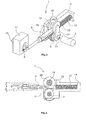
- the adjusting device 1 has an electric drive device 2, which acts on a toothed rack 6 via a gear element designed as a gear pinion 4.
- the rack 6 is connected via a coupling member 8 with a rotation axis 10 of an actuator not shown.
- the axis of rotation 10 is here exemplarily mounted in a housing 1.
- actuators come here in particular flap elements in question.
- At the Coupling member 8 opposite end of the rack 6 is mounted via a spring member 12 in a housing 14 shown schematically.
- the spring member 12 is designed as a compression spring. In this way it is ensured that in each operating state, the meshing tooth flank of the rack 6 is pressed against the respective tooth flank of the gear pinion 4 and so takes place a one-sided play-free positioning. In the unloaded state, a defined clearance between the rack 6 and gear pinion 4 is provided, which is advantageous in relation to the pivoting of the rack 6.
- a starting element 16 is provided, that the rack 6 pre-positioned radially in the direction of the axis of rotation 17 of the gear pinion 4.
- the starting element 16 is designed as a starting roller.
- this run-up roller 16 is rotatably mounted about the axis of rotation 17 of the Zahnradritzels 4, whereby the pivot angle of the rack 6 can be increased once again.
- the run-up roller 16 guide surfaces 18, 20, which ensure a lateral guidance of the rack 6. It should be clear that, of course, a fixed start-up profile can be used as starting element 16.
- FIG. 2 now shows the actuator 1 in a side view without coupling member 8. Clearly visible here is the possible on both sides of the rack 6 pivot angle a.
- the rack 6 has a conical end piece 22, which extends into the compression spring 12, whereby the pivoting ability of the rack can be further improved.
- the rack 6 and the gear pinion 4 form in the present embodiment, an involute toothing.
- starting roller 16 with a corresponding toothing, so that it can be used as a second drive pinion.
Landscapes
- Engineering & Computer Science (AREA)
- General Engineering & Computer Science (AREA)
- Mechanical Engineering (AREA)
- Transmission Devices (AREA)
Abstract
Description
Die Erfindung betrifft eine Stellvorrichtung zur Verstellung von Stellgliedern in einer Brennkraftmaschine mit einer elektrischen Antriebseinrichtung, die über mindestens ein Getriebeelement auf ein Verstellorgan einwirkt, das über ein Koppelorgan mit einer Drehachse des Stellgliedes verbunden ist.The invention relates to an adjusting device for adjusting actuators in an internal combustion engine with an electric drive device which acts via at least one transmission element on an adjusting member which is connected via a coupling member with a rotational axis of the actuator.
Stellvorrichtungen dieser Art dienen insbesondere zur Verstellung von Schaltklappen, die in Luftansaugkanalsystemen, als Drosselklappen, als Abgasklappen oder auch als sogenannte Waste-Gate-Klappen eingesetzt werden. Bisher werden häufig für derartige Aufgaben in Brennkraftmaschinen Unterdruckdosen eingesetzt. Ein Ersatz dieser Unterdruckdosen wird insbesondere erforderlich, da die gestiegenen Regelstell.Anforderungen nur mit einem elektromotorischen Antrieb realisiert werden können.Actuators of this type are used in particular for the adjustment of switching flaps that are used in Luftansaugkanalsystemen, as throttle valves, as exhaust valves or as so-called waste gate flaps. So far, vacuum cans are often used for such tasks in internal combustion engines. A replacement of these vacuum cans is particularly necessary because the increased Regelstell.Anforderungen can only be realized with an electric motor drive.
Als Ersatz für diese Unterdruckdosen sind elektrische Antriebseinrichtungen geeignet. Eine Stellvorrichtung mit elektrischer Antriebseinrichtung ist beispielsweise aus der
Der Erfindung liegt daher die Aufgabe zugrunde, eine Stellvorrichtung mit elektrischer Antriebseinheit zu schaffen, die hinsichtlich Bauform, Baugröße und Bewegungsgraden einer herkömmlichen Stellvorrichtung mit Unterdruckdose entspricht.The invention is therefore an object of the invention to provide a control device with electric drive unit, which corresponds in terms of design, size and degrees of movement of a conventional actuator with vacuum box.
Die Aufgabe wird dadurch gelöst, dass das Verstellorgan zumindest teilweise als Zahnstange ausgebildet ist, die über ein Federorgan an dem dem Koppelorgan entgegen gesetzten Ende in einem Gehäuse gelagert ist, wobei ein Anlaufelement die Zahnstange radial in Richtung der Drehachse des Getriebeelementes positioniert. Hierdurch wird auf besonders einfache Art und Weise eine Stellvorrichtung geschaffen, die eine Linearbewegung des Verstellorgans bei gleichzeitiger möglicher Schwenkbewegung gewährleistet. Dabei ist es besonders vorteilhaft, wenn das auf die Zahnstange einwirkende Getriebeelement als Zahnradritzel ausgeführt ist, wobei die Schwenkbewegung als Abwälzbewegung über das Zahnradritzel stattfindet.The object is achieved in that the adjusting member is at least partially formed as a rack which is mounted via a spring member on the opposite end of the coupling member in a housing, wherein a starting element positions the rack radially in the direction of the axis of rotation of the transmission element. As a result, an adjusting device is provided in a particularly simple manner, which ensures a linear movement of the adjusting while a possible pivoting movement. It is particularly advantageous if the gear acting on the rack gear element is designed as a gear pinion, wherein the pivoting movement takes place as a rolling movement over the gear pinion.
Auf einfache Weise kann das Anlaufelement als feststehendes Anlaufprofil ausgeführt sein. Hierbei können kleine Schwenkbewegungen der Zahnstange durch ein definiertes Spiel zwischen Zahnradritzel, Zahnstange und Anlaufprofile ermöglicht werden. Es ist jedoch auch möglich und vorteilhaft, das Anlaufelement als Anlaufrolle auszuführen, wobei die Anlaufrolle seitliche Führungsflächen zur Führung der Zahnstange aufweist kann.In a simple way, the starting element can be designed as a fixed start-up profile. This small pivoting movements of the rack can be made possible by a defined game between gear pinion, rack and run-up profiles. However, it is also possible and advantageous to carry out the starting element as a starting roller, wherein the starting roller may have lateral guide surfaces for guiding the rack.
Um größere Schwenkbewegungen zu ermöglichen, kann die Anlaufrolle drehbar um die Zahnradritzelachse gelagert sein.In order to allow greater pivoting movements, the run-up roller can be rotatably mounted around the gear pinion axis.
Das Federorgan ist vorzugsweise als Druckfeder ausgeführt, wodurch eine vorgespannte und einseitig spielfreie Positionierung der Verzahnung von Zahnstange und beispielsweise Zahnradritzel gewährleistet ist. Beispielsweise ist eine relativ leicht bewegliche Druckfedertellerlagerung in kegelstumpfförmigen Ansatzstücken in der Lage, die gewünschte und erforderliche Schwenkbewegung um die Zahnritzelachse zuzulassen.The spring member is preferably designed as a compression spring, whereby a prestressed and one-sided play-free positioning of the toothing of the rack and for example gear pinion is ensured. For example, a relatively easily movable pressure spring bearing in frusto-conical extensions is capable of allowing the desired and required pivotal movement about the pinion axis.
Wenn das Zahnritzel und die Zahnstange eine Rundverzahnung aufweisen, kann eine größere Schwenkbewegung und somit ein größerer Fluchtungsversatz zwischen dem Ende des Verstellorgans und dem Angriffspunkt des Spannelementes vorgenommen werden. Dieser Effekt kann auch dadurch erwirkt werden, dass die Zahnstange ein kegelstumpfförmiges Ansatzstück aufweist, das in das Federelement hineinreicht.If the pinion and the rack have a round teeth, a greater pivotal movement and thus a greater alignment offset between the end of the adjusting and the point of the clamping element can be made. This effect can also be achieved in that the rack has a frusto-conical extension which extends into the spring element.
Nachfolgend wird die Erfindung anhand einer bevorzugten Ausführungsform unter Bezugnahme auf die anliegende Zeichnung näher erläutert, hierin zeigt:
-
Figur 1 -
Figur 2
-
FIG. 1 a perspective view of the invention, and -
FIG. 2 a side view of a portion of the adjusting device according to the invention.
Die erfindungsgemäße Stellvorrichtung 1 weist eine elektrische Antriebseinrichtung 2 auf, die über ein als Zahnradritzel 4 ausgebildetes Getriebeelement auf eine Zahnstange 6 einwirkt. Die Zahnstange 6 ist über ein Koppelorgan 8 mit einer Drehachse 10 eines nicht weiter dargestellten Stellgliedes verbunden. Die Drehachse 10 ist hier exemplarisch in einem Gehäuse 1 gelagert. Als Stellglieder kommen hierbei insbesondere Klappenelemente in Frage. An dem dem Koppelorgan 8 entgegengesetzten Ende ist die Zahnstange 6 über ein Federorgan 12 in einem schematisch dargestellten Gehäuse 14 gelagert. Im vorliegenden Ausführungsbeispiel ist das Federorgan 12 als Druckfeder ausgeführt. Auf diese Weise ist gewährleistet, dass in jedem Betriebszustand die im Eingriff stehende Zahnflanke der Zahnstange 6 gegen die jeweilige Zahnflanke des Zahnradritzels 4 gedrückt wird und so eine einseitig spielfreie Positionierung stattfindet. Im unbelasteten Zustand ist ein definiertes Spiel zwischen Zahnstange 6 und Zahnradritzel 4 vorgesehen, was vorteilhaft in Bezug auf die Schwenkbarkeit der Zahnstange 6 ist.The adjusting
Im Bereich des Zahnradritzels 4 ist ein Anlaufelement 16 vorgesehen, dass die Zahnstange 6 radial in Richtung der Drehachse 17 des Zahnradritzels 4 vorpositioniert. Durch diese besondere Anordnung ist eine Schwenkbarkeit der Zahnstange 6 um die Drehachse 17 des Zahnradritzels 4 gewährleistet. Im vorliegenden Fall ist das Anlaufelement 16 als Anlaufrolle ausgeführt. Über ein Lagerelement 24 ist diese Anlaufrolle 16 drehbar um die Drehachse 17 des Zahnradritzels 4 gelagert, wodurch der Schwenkwinkel der Zahnstange 6 noch einmal vergrößert werden kann. Darüber hinaus weist die Anlaufrolle 16 Führungsflächen 18, 20 auf, die eine seitliche Führung der Zahnstange 6 gewährleisten. Es sollte deutlich sein, dass natürlich auch ein feststehendes Anlaufprofil als Anlaufelement 16 eingesetzt werden kann.In the area of the
Die Zahnstange 6 und das Zahnradritzel 4 bilden im vorliegenden Ausführungsbeispiel eine Evolventenverzahnung. Natürlich ist es auch möglich, die Verzahnung als Zykloiden-Verzahnung auszuführen, wodurch die Schwenkbarkeit noch ein wenig erhöht werden kann.The
Auch ist es denkbar die Anlaufrolle 16 noch mit einer entsprechenden Verzahnung zu versehen, so dass diese als zweites Antriebsritzel zu nutzen ist.It is also conceivable to provide the
Claims (9)
Applications Claiming Priority (1)
| Application Number | Priority Date | Filing Date | Title |
|---|---|---|---|
| DE102011012203A DE102011012203A1 (en) | 2011-02-23 | 2011-02-23 | Adjusting device for adjusting actuators in an internal combustion engine |
Publications (2)
| Publication Number | Publication Date |
|---|---|
| EP2492469A1 true EP2492469A1 (en) | 2012-08-29 |
| EP2492469B1 EP2492469B1 (en) | 2013-08-21 |
Family
ID=45217387
Family Applications (1)
| Application Number | Title | Priority Date | Filing Date |
|---|---|---|---|
| EP20110191875 Not-in-force EP2492469B1 (en) | 2011-02-23 | 2011-12-05 | Control for adjusting regulator control elements in an internal combustion engine |
Country Status (2)
| Country | Link |
|---|---|
| EP (1) | EP2492469B1 (en) |
| DE (1) | DE102011012203A1 (en) |
Cited By (1)
| Publication number | Priority date | Publication date | Assignee | Title |
|---|---|---|---|---|
| EP2607644B1 (en) * | 2011-12-21 | 2017-02-01 | Valeo Systèmes de Contrôle Moteur | Rack and pinion control actuator |
Families Citing this family (1)
| Publication number | Priority date | Publication date | Assignee | Title |
|---|---|---|---|---|
| DE202016105970U1 (en) * | 2016-10-24 | 2016-11-10 | Lock Antriebstechnik Gmbh | Transmission device for attachment to a drive shaft |
Citations (6)
| Publication number | Priority date | Publication date | Assignee | Title |
|---|---|---|---|---|
| GB2113797A (en) * | 1982-01-22 | 1983-08-10 | Dowty Rotol Ltd | Rack-and-pinion device |
| GB2142410A (en) * | 1983-07-01 | 1985-01-16 | Ciniglio A J | Improvements in or relating to linear actuators |
| US20030116146A1 (en) * | 2001-12-21 | 2003-06-26 | Rod Fensom | High speed exhaust gas recirculation valve |
| JP2006125231A (en) * | 2004-10-27 | 2006-05-18 | Hitachi Ltd | Electronically controlled throttle for engine |
| WO2006097884A1 (en) * | 2005-03-14 | 2006-09-21 | Dell'orto S.P.A. | Egr valve in internal combustion engines actuated by electric motor with rack and pinion |
| DE102005052966A1 (en) | 2005-11-07 | 2007-05-10 | Pierburg Gmbh | Adjusting device for adjusting of components in internal combustion engine, has gearbox unit which is formed as spur gear and spring element accelerates driving unit after exceeding breakover point |
Family Cites Families (3)
| Publication number | Priority date | Publication date | Assignee | Title |
|---|---|---|---|---|
| GB8317968D0 (en) * | 1983-07-01 | 1983-08-03 | Ciniglio A J | Linear actuators |
| DE4411630C1 (en) * | 1994-04-02 | 1995-06-08 | Audi Ag | Control system for throttle flap in combustion engine |
| DE10314358B4 (en) * | 2003-03-31 | 2013-04-04 | Schaeffler Technologies AG & Co. KG | Rack and pinion steering |
-
2011
- 2011-02-23 DE DE102011012203A patent/DE102011012203A1/en not_active Withdrawn
- 2011-12-05 EP EP20110191875 patent/EP2492469B1/en not_active Not-in-force
Patent Citations (6)
| Publication number | Priority date | Publication date | Assignee | Title |
|---|---|---|---|---|
| GB2113797A (en) * | 1982-01-22 | 1983-08-10 | Dowty Rotol Ltd | Rack-and-pinion device |
| GB2142410A (en) * | 1983-07-01 | 1985-01-16 | Ciniglio A J | Improvements in or relating to linear actuators |
| US20030116146A1 (en) * | 2001-12-21 | 2003-06-26 | Rod Fensom | High speed exhaust gas recirculation valve |
| JP2006125231A (en) * | 2004-10-27 | 2006-05-18 | Hitachi Ltd | Electronically controlled throttle for engine |
| WO2006097884A1 (en) * | 2005-03-14 | 2006-09-21 | Dell'orto S.P.A. | Egr valve in internal combustion engines actuated by electric motor with rack and pinion |
| DE102005052966A1 (en) | 2005-11-07 | 2007-05-10 | Pierburg Gmbh | Adjusting device for adjusting of components in internal combustion engine, has gearbox unit which is formed as spur gear and spring element accelerates driving unit after exceeding breakover point |
Cited By (1)
| Publication number | Priority date | Publication date | Assignee | Title |
|---|---|---|---|---|
| EP2607644B1 (en) * | 2011-12-21 | 2017-02-01 | Valeo Systèmes de Contrôle Moteur | Rack and pinion control actuator |
Also Published As
| Publication number | Publication date |
|---|---|
| DE102011012203A1 (en) | 2012-08-23 |
| EP2492469B1 (en) | 2013-08-21 |
Similar Documents
| Publication | Publication Date | Title |
|---|---|---|
| EP2458182B1 (en) | Equipment for influencing gas volume flows, method for control and/or regulation of an exhaust gas flow or a charge air flow, exhaust gas line and vehicle | |
| EP2676020B1 (en) | Actuator, flow valve, turbocharger | |
| EP2172682A1 (en) | Exhaust gas recirculation valve | |
| EP2418373A1 (en) | Actuator and waste gas reclaiming valve, wastegate or variable turbine geometry with an actuator | |
| EP2954181B1 (en) | Turbocharger with control linkage | |
| DE3927043A1 (en) | LOAD ADJUSTMENT DEVICE | |
| DE102006054041B3 (en) | Regulating device for an internal combustion engine | |
| DE102013109997A1 (en) | actuator | |
| DE102007032432B4 (en) | INTERNAL COMBUSTION ENGINES WITH A VARIABLE TRANSMISSION RATIO AND VALVE THEREFOR | |
| EP2492469B1 (en) | Control for adjusting regulator control elements in an internal combustion engine | |
| DE102008020909B4 (en) | Decompression device for an internal combustion engine | |
| AT508984A1 (en) | TRAIN PRINT ROD | |
| EP2521846B1 (en) | Transmission arrangement and turbo charger | |
| DE102017212073A1 (en) | Rack and pinion for a motor vehicle | |
| DE102014002455B4 (en) | Swivel drive for adjusting adjustable body parts, e.g. Air baffles and / or spoiler od. Like., Of a motor vehicle | |
| EP3073072B1 (en) | Mechanically controllable valve drive and mechanically controllable valve drive assembly | |
| EP3014080A1 (en) | Spring arrangement for a variable valve drive of an internal combustion engine | |
| EP3927997B1 (en) | Ball screw drive with an anti-rotation device | |
| DE102012204780A1 (en) | Rotatable drive connection that reduces rattling | |
| EP2072861B1 (en) | Anti-twist device with tolerance balance | |
| DE102016116319B4 (en) | Sliding door gearbox with over-center locking | |
| EP3835621B1 (en) | Actuator | |
| EP2689112B1 (en) | Mechanically controllable valve drive and mechanically controllable valve drive arrangement | |
| EP2453155B1 (en) | Valve with an Actuating Device | |
| EP3996973B1 (en) | Electromechanical power steering system having a pivot-pendulum bearing assembly |
Legal Events
| Date | Code | Title | Description |
|---|---|---|---|
| PUAI | Public reference made under article 153(3) epc to a published international application that has entered the european phase |
Free format text: ORIGINAL CODE: 0009012 |
|
| AK | Designated contracting states |
Kind code of ref document: A1 Designated state(s): AL AT BE BG CH CY CZ DE DK EE ES FI FR GB GR HR HU IE IS IT LI LT LU LV MC MK MT NL NO PL PT RO RS SE SI SK SM TR |
|
| AX | Request for extension of the european patent |
Extension state: BA ME |
|
| 17P | Request for examination filed |
Effective date: 20130213 |
|
| GRAP | Despatch of communication of intention to grant a patent |
Free format text: ORIGINAL CODE: EPIDOSNIGR1 |
|
| INTG | Intention to grant announced |
Effective date: 20130410 |
|
| GRAS | Grant fee paid |
Free format text: ORIGINAL CODE: EPIDOSNIGR3 |
|
| GRAA | (expected) grant |
Free format text: ORIGINAL CODE: 0009210 |
|
| AK | Designated contracting states |
Kind code of ref document: B1 Designated state(s): AL AT BE BG CH CY CZ DE DK EE ES FI FR GB GR HR HU IE IS IT LI LT LU LV MC MK MT NL NO PL PT RO RS SE SI SK SM TR |
|
| REG | Reference to a national code |
Ref country code: GB Ref legal event code: FG4D Free format text: NOT ENGLISH |
|
| REG | Reference to a national code |
Ref country code: CH Ref legal event code: EP |
|
| REG | Reference to a national code |
Ref country code: AT Ref legal event code: REF Ref document number: 628249 Country of ref document: AT Kind code of ref document: T Effective date: 20130915 |
|
| REG | Reference to a national code |
Ref country code: IE Ref legal event code: FG4D Free format text: LANGUAGE OF EP DOCUMENT: GERMAN |
|
| REG | Reference to a national code |
Ref country code: DE Ref legal event code: R096 Ref document number: 502011001209 Country of ref document: DE Effective date: 20131024 |
|
| REG | Reference to a national code |
Ref country code: NL Ref legal event code: VDEP Effective date: 20130821 |
|
| REG | Reference to a national code |
Ref country code: LT Ref legal event code: MG4D |
|
| PG25 | Lapsed in a contracting state [announced via postgrant information from national office to epo] |
Ref country code: PT Free format text: LAPSE BECAUSE OF FAILURE TO SUBMIT A TRANSLATION OF THE DESCRIPTION OR TO PAY THE FEE WITHIN THE PRESCRIBED TIME-LIMIT Effective date: 20131223 Ref country code: CY Free format text: LAPSE BECAUSE OF FAILURE TO SUBMIT A TRANSLATION OF THE DESCRIPTION OR TO PAY THE FEE WITHIN THE PRESCRIBED TIME-LIMIT Effective date: 20130911 Ref country code: SE Free format text: LAPSE BECAUSE OF FAILURE TO SUBMIT A TRANSLATION OF THE DESCRIPTION OR TO PAY THE FEE WITHIN THE PRESCRIBED TIME-LIMIT Effective date: 20130821 Ref country code: LT Free format text: LAPSE BECAUSE OF FAILURE TO SUBMIT A TRANSLATION OF THE DESCRIPTION OR TO PAY THE FEE WITHIN THE PRESCRIBED TIME-LIMIT Effective date: 20130821 Ref country code: NO Free format text: LAPSE BECAUSE OF FAILURE TO SUBMIT A TRANSLATION OF THE DESCRIPTION OR TO PAY THE FEE WITHIN THE PRESCRIBED TIME-LIMIT Effective date: 20131121 Ref country code: HR Free format text: LAPSE BECAUSE OF FAILURE TO SUBMIT A TRANSLATION OF THE DESCRIPTION OR TO PAY THE FEE WITHIN THE PRESCRIBED TIME-LIMIT Effective date: 20130821 Ref country code: IS Free format text: LAPSE BECAUSE OF FAILURE TO SUBMIT A TRANSLATION OF THE DESCRIPTION OR TO PAY THE FEE WITHIN THE PRESCRIBED TIME-LIMIT Effective date: 20131221 |
|
| PG25 | Lapsed in a contracting state [announced via postgrant information from national office to epo] |
Ref country code: GR Free format text: LAPSE BECAUSE OF FAILURE TO SUBMIT A TRANSLATION OF THE DESCRIPTION OR TO PAY THE FEE WITHIN THE PRESCRIBED TIME-LIMIT Effective date: 20131122 Ref country code: FI Free format text: LAPSE BECAUSE OF FAILURE TO SUBMIT A TRANSLATION OF THE DESCRIPTION OR TO PAY THE FEE WITHIN THE PRESCRIBED TIME-LIMIT Effective date: 20130821 Ref country code: LV Free format text: LAPSE BECAUSE OF FAILURE TO SUBMIT A TRANSLATION OF THE DESCRIPTION OR TO PAY THE FEE WITHIN THE PRESCRIBED TIME-LIMIT Effective date: 20130821 Ref country code: SI Free format text: LAPSE BECAUSE OF FAILURE TO SUBMIT A TRANSLATION OF THE DESCRIPTION OR TO PAY THE FEE WITHIN THE PRESCRIBED TIME-LIMIT Effective date: 20130821 Ref country code: PL Free format text: LAPSE BECAUSE OF FAILURE TO SUBMIT A TRANSLATION OF THE DESCRIPTION OR TO PAY THE FEE WITHIN THE PRESCRIBED TIME-LIMIT Effective date: 20130821 |
|
| PG25 | Lapsed in a contracting state [announced via postgrant information from national office to epo] |
Ref country code: CY Free format text: LAPSE BECAUSE OF FAILURE TO SUBMIT A TRANSLATION OF THE DESCRIPTION OR TO PAY THE FEE WITHIN THE PRESCRIBED TIME-LIMIT Effective date: 20130821 |
|
| PG25 | Lapsed in a contracting state [announced via postgrant information from national office to epo] |
Ref country code: CZ Free format text: LAPSE BECAUSE OF FAILURE TO SUBMIT A TRANSLATION OF THE DESCRIPTION OR TO PAY THE FEE WITHIN THE PRESCRIBED TIME-LIMIT Effective date: 20130821 Ref country code: DK Free format text: LAPSE BECAUSE OF FAILURE TO SUBMIT A TRANSLATION OF THE DESCRIPTION OR TO PAY THE FEE WITHIN THE PRESCRIBED TIME-LIMIT Effective date: 20130821 Ref country code: SK Free format text: LAPSE BECAUSE OF FAILURE TO SUBMIT A TRANSLATION OF THE DESCRIPTION OR TO PAY THE FEE WITHIN THE PRESCRIBED TIME-LIMIT Effective date: 20130821 Ref country code: RO Free format text: LAPSE BECAUSE OF FAILURE TO SUBMIT A TRANSLATION OF THE DESCRIPTION OR TO PAY THE FEE WITHIN THE PRESCRIBED TIME-LIMIT Effective date: 20130821 Ref country code: NL Free format text: LAPSE BECAUSE OF FAILURE TO SUBMIT A TRANSLATION OF THE DESCRIPTION OR TO PAY THE FEE WITHIN THE PRESCRIBED TIME-LIMIT Effective date: 20130821 Ref country code: EE Free format text: LAPSE BECAUSE OF FAILURE TO SUBMIT A TRANSLATION OF THE DESCRIPTION OR TO PAY THE FEE WITHIN THE PRESCRIBED TIME-LIMIT Effective date: 20130821 |
|
| PG25 | Lapsed in a contracting state [announced via postgrant information from national office to epo] |
Ref country code: IT Free format text: LAPSE BECAUSE OF FAILURE TO SUBMIT A TRANSLATION OF THE DESCRIPTION OR TO PAY THE FEE WITHIN THE PRESCRIBED TIME-LIMIT Effective date: 20130821 Ref country code: ES Free format text: LAPSE BECAUSE OF FAILURE TO SUBMIT A TRANSLATION OF THE DESCRIPTION OR TO PAY THE FEE WITHIN THE PRESCRIBED TIME-LIMIT Effective date: 20130821 |
|
| PLBE | No opposition filed within time limit |
Free format text: ORIGINAL CODE: 0009261 |
|
| STAA | Information on the status of an ep patent application or granted ep patent |
Free format text: STATUS: NO OPPOSITION FILED WITHIN TIME LIMIT |
|
| BERE | Be: lapsed |
Owner name: PIERBURG G.M.B.H. Effective date: 20131231 |
|
| 26N | No opposition filed |
Effective date: 20140522 |
|
| PG25 | Lapsed in a contracting state [announced via postgrant information from national office to epo] |
Ref country code: LU Free format text: LAPSE BECAUSE OF FAILURE TO SUBMIT A TRANSLATION OF THE DESCRIPTION OR TO PAY THE FEE WITHIN THE PRESCRIBED TIME-LIMIT Effective date: 20131205 |
|
| REG | Reference to a national code |
Ref country code: DE Ref legal event code: R097 Ref document number: 502011001209 Country of ref document: DE Effective date: 20140522 |
|
| REG | Reference to a national code |
Ref country code: IE Ref legal event code: MM4A |
|
| REG | Reference to a national code |
Ref country code: FR Ref legal event code: ST Effective date: 20140829 |
|
| PG25 | Lapsed in a contracting state [announced via postgrant information from national office to epo] |
Ref country code: BE Free format text: LAPSE BECAUSE OF NON-PAYMENT OF DUE FEES Effective date: 20131231 Ref country code: IE Free format text: LAPSE BECAUSE OF NON-PAYMENT OF DUE FEES Effective date: 20131205 |
|
| PG25 | Lapsed in a contracting state [announced via postgrant information from national office to epo] |
Ref country code: FR Free format text: LAPSE BECAUSE OF NON-PAYMENT OF DUE FEES Effective date: 20131231 |
|
| PG25 | Lapsed in a contracting state [announced via postgrant information from national office to epo] |
Ref country code: MC Free format text: LAPSE BECAUSE OF FAILURE TO SUBMIT A TRANSLATION OF THE DESCRIPTION OR TO PAY THE FEE WITHIN THE PRESCRIBED TIME-LIMIT Effective date: 20130821 |
|
| PG25 | Lapsed in a contracting state [announced via postgrant information from national office to epo] |
Ref country code: SM Free format text: LAPSE BECAUSE OF FAILURE TO SUBMIT A TRANSLATION OF THE DESCRIPTION OR TO PAY THE FEE WITHIN THE PRESCRIBED TIME-LIMIT Effective date: 20130821 |
|
| PG25 | Lapsed in a contracting state [announced via postgrant information from national office to epo] |
Ref country code: MK Free format text: LAPSE BECAUSE OF FAILURE TO SUBMIT A TRANSLATION OF THE DESCRIPTION OR TO PAY THE FEE WITHIN THE PRESCRIBED TIME-LIMIT Effective date: 20130821 Ref country code: BG Free format text: LAPSE BECAUSE OF FAILURE TO SUBMIT A TRANSLATION OF THE DESCRIPTION OR TO PAY THE FEE WITHIN THE PRESCRIBED TIME-LIMIT Effective date: 20130821 Ref country code: HU Free format text: LAPSE BECAUSE OF FAILURE TO SUBMIT A TRANSLATION OF THE DESCRIPTION OR TO PAY THE FEE WITHIN THE PRESCRIBED TIME-LIMIT; INVALID AB INITIO Effective date: 20111205 Ref country code: RS Free format text: LAPSE BECAUSE OF FAILURE TO SUBMIT A TRANSLATION OF THE DESCRIPTION OR TO PAY THE FEE WITHIN THE PRESCRIBED TIME-LIMIT Effective date: 20131121 |
|
| REG | Reference to a national code |
Ref country code: CH Ref legal event code: PL |
|
| PG25 | Lapsed in a contracting state [announced via postgrant information from national office to epo] |
Ref country code: MT Free format text: LAPSE BECAUSE OF FAILURE TO SUBMIT A TRANSLATION OF THE DESCRIPTION OR TO PAY THE FEE WITHIN THE PRESCRIBED TIME-LIMIT Effective date: 20130821 |
|
| PG25 | Lapsed in a contracting state [announced via postgrant information from national office to epo] |
Ref country code: CH Free format text: LAPSE BECAUSE OF NON-PAYMENT OF DUE FEES Effective date: 20141231 Ref country code: LI Free format text: LAPSE BECAUSE OF NON-PAYMENT OF DUE FEES Effective date: 20141231 |
|
| PG25 | Lapsed in a contracting state [announced via postgrant information from national office to epo] |
Ref country code: TR Free format text: LAPSE BECAUSE OF FAILURE TO SUBMIT A TRANSLATION OF THE DESCRIPTION OR TO PAY THE FEE WITHIN THE PRESCRIBED TIME-LIMIT Effective date: 20130821 |
|
| GBPC | Gb: european patent ceased through non-payment of renewal fee |
Effective date: 20151205 |
|
| PG25 | Lapsed in a contracting state [announced via postgrant information from national office to epo] |
Ref country code: GB Free format text: LAPSE BECAUSE OF NON-PAYMENT OF DUE FEES Effective date: 20151205 |
|
| REG | Reference to a national code |
Ref country code: AT Ref legal event code: MM01 Ref document number: 628249 Country of ref document: AT Kind code of ref document: T Effective date: 20161205 |
|
| PG25 | Lapsed in a contracting state [announced via postgrant information from national office to epo] |
Ref country code: AT Free format text: LAPSE BECAUSE OF NON-PAYMENT OF DUE FEES Effective date: 20161205 |
|
| PG25 | Lapsed in a contracting state [announced via postgrant information from national office to epo] |
Ref country code: AL Free format text: LAPSE BECAUSE OF FAILURE TO SUBMIT A TRANSLATION OF THE DESCRIPTION OR TO PAY THE FEE WITHIN THE PRESCRIBED TIME-LIMIT Effective date: 20130821 |
|
| PGFP | Annual fee paid to national office [announced via postgrant information from national office to epo] |
Ref country code: DE Payment date: 20191217 Year of fee payment: 9 |
|
| REG | Reference to a national code |
Ref country code: DE Ref legal event code: R082 Ref document number: 502011001209 Country of ref document: DE Representative=s name: TERPATENT PATENTANWAELTE TER SMITTEN EBERLEIN-, DE |
|
| REG | Reference to a national code |
Ref country code: DE Ref legal event code: R119 Ref document number: 502011001209 Country of ref document: DE |
|
| PG25 | Lapsed in a contracting state [announced via postgrant information from national office to epo] |
Ref country code: DE Free format text: LAPSE BECAUSE OF NON-PAYMENT OF DUE FEES Effective date: 20210701 |