EP2492466A2 - Decomposition conduit fabrication method - Google Patents
Decomposition conduit fabrication method Download PDFInfo
- Publication number
- EP2492466A2 EP2492466A2 EP12154712A EP12154712A EP2492466A2 EP 2492466 A2 EP2492466 A2 EP 2492466A2 EP 12154712 A EP12154712 A EP 12154712A EP 12154712 A EP12154712 A EP 12154712A EP 2492466 A2 EP2492466 A2 EP 2492466A2
- Authority
- EP
- European Patent Office
- Prior art keywords
- decomposition
- sand core
- static mixer
- decomposition conduit
- mold
- Prior art date
- Legal status (The legal status is an assumption and is not a legal conclusion. Google has not performed a legal analysis and makes no representation as to the accuracy of the status listed.)
- Withdrawn
Links
Images


Classifications
-
- F—MECHANICAL ENGINEERING; LIGHTING; HEATING; WEAPONS; BLASTING
- F01—MACHINES OR ENGINES IN GENERAL; ENGINE PLANTS IN GENERAL; STEAM ENGINES
- F01N—GAS-FLOW SILENCERS OR EXHAUST APPARATUS FOR MACHINES OR ENGINES IN GENERAL; GAS-FLOW SILENCERS OR EXHAUST APPARATUS FOR INTERNAL-COMBUSTION ENGINES
- F01N13/00—Exhaust or silencing apparatus characterised by constructional features
- F01N13/18—Construction facilitating manufacture, assembly, or disassembly
- F01N13/1861—Construction facilitating manufacture, assembly, or disassembly the assembly using parts formed by casting or moulding
-
- B—PERFORMING OPERATIONS; TRANSPORTING
- B01—PHYSICAL OR CHEMICAL PROCESSES OR APPARATUS IN GENERAL
- B01F—MIXING, e.g. DISSOLVING, EMULSIFYING OR DISPERSING
- B01F23/00—Mixing according to the phases to be mixed, e.g. dispersing or emulsifying
- B01F23/20—Mixing gases with liquids
- B01F23/21—Mixing gases with liquids by introducing liquids into gaseous media
- B01F23/213—Mixing gases with liquids by introducing liquids into gaseous media by spraying or atomising of the liquids
- B01F23/2132—Mixing gases with liquids by introducing liquids into gaseous media by spraying or atomising of the liquids using nozzles
-
- B—PERFORMING OPERATIONS; TRANSPORTING
- B01—PHYSICAL OR CHEMICAL PROCESSES OR APPARATUS IN GENERAL
- B01F—MIXING, e.g. DISSOLVING, EMULSIFYING OR DISPERSING
- B01F25/00—Flow mixers; Mixers for falling materials, e.g. solid particles
- B01F25/30—Injector mixers
- B01F25/31—Injector mixers in conduits or tubes through which the main component flows
- B01F25/313—Injector mixers in conduits or tubes through which the main component flows wherein additional components are introduced in the centre of the conduit
- B01F25/3131—Injector mixers in conduits or tubes through which the main component flows wherein additional components are introduced in the centre of the conduit with additional mixing means other than injector mixers, e.g. screens, baffles or rotating elements
-
- B—PERFORMING OPERATIONS; TRANSPORTING
- B01—PHYSICAL OR CHEMICAL PROCESSES OR APPARATUS IN GENERAL
- B01F—MIXING, e.g. DISSOLVING, EMULSIFYING OR DISPERSING
- B01F25/00—Flow mixers; Mixers for falling materials, e.g. solid particles
- B01F25/40—Static mixers
- B01F25/42—Static mixers in which the mixing is affected by moving the components jointly in changing directions, e.g. in tubes provided with baffles or obstructions
- B01F25/43—Mixing tubes, e.g. wherein the material is moved in a radial or partly reversed direction
- B01F25/431—Straight mixing tubes with baffles or obstructions that do not cause substantial pressure drop; Baffles therefor
- B01F25/4316—Straight mixing tubes with baffles or obstructions that do not cause substantial pressure drop; Baffles therefor the baffles being flat pieces of material, e.g. intermeshing, fixed to the wall or fixed on a central rod
-
- B—PERFORMING OPERATIONS; TRANSPORTING
- B22—CASTING; POWDER METALLURGY
- B22C—FOUNDRY MOULDING
- B22C9/00—Moulds or cores; Moulding processes
- B22C9/02—Sand moulds or like moulds for shaped castings
-
- B—PERFORMING OPERATIONS; TRANSPORTING
- B22—CASTING; POWDER METALLURGY
- B22C—FOUNDRY MOULDING
- B22C9/00—Moulds or cores; Moulding processes
- B22C9/10—Cores; Manufacture or installation of cores
-
- B—PERFORMING OPERATIONS; TRANSPORTING
- B22—CASTING; POWDER METALLURGY
- B22D—CASTING OF METALS; CASTING OF OTHER SUBSTANCES BY THE SAME PROCESSES OR DEVICES
- B22D29/00—Removing castings from moulds, not restricted to casting processes covered by a single main group; Removing cores; Handling ingots
- B22D29/001—Removing cores
-
- F—MECHANICAL ENGINEERING; LIGHTING; HEATING; WEAPONS; BLASTING
- F01—MACHINES OR ENGINES IN GENERAL; ENGINE PLANTS IN GENERAL; STEAM ENGINES
- F01N—GAS-FLOW SILENCERS OR EXHAUST APPARATUS FOR MACHINES OR ENGINES IN GENERAL; GAS-FLOW SILENCERS OR EXHAUST APPARATUS FOR INTERNAL-COMBUSTION ENGINES
- F01N3/00—Exhaust or silencing apparatus having means for purifying, rendering innocuous, or otherwise treating exhaust
- F01N3/08—Exhaust or silencing apparatus having means for purifying, rendering innocuous, or otherwise treating exhaust for rendering innocuous
- F01N3/10—Exhaust or silencing apparatus having means for purifying, rendering innocuous, or otherwise treating exhaust for rendering innocuous by thermal or catalytic conversion of noxious components of exhaust
- F01N3/18—Exhaust or silencing apparatus having means for purifying, rendering innocuous, or otherwise treating exhaust for rendering innocuous by thermal or catalytic conversion of noxious components of exhaust characterised by methods of operation; Control
- F01N3/20—Exhaust or silencing apparatus having means for purifying, rendering innocuous, or otherwise treating exhaust for rendering innocuous by thermal or catalytic conversion of noxious components of exhaust characterised by methods of operation; Control specially adapted for catalytic conversion
- F01N3/206—Adding periodically or continuously substances to exhaust gases for promoting purification, e.g. catalytic material in liquid form, NOx reducing agents
- F01N3/2066—Selective catalytic reduction [SCR]
-
- F—MECHANICAL ENGINEERING; LIGHTING; HEATING; WEAPONS; BLASTING
- F01—MACHINES OR ENGINES IN GENERAL; ENGINE PLANTS IN GENERAL; STEAM ENGINES
- F01N—GAS-FLOW SILENCERS OR EXHAUST APPARATUS FOR MACHINES OR ENGINES IN GENERAL; GAS-FLOW SILENCERS OR EXHAUST APPARATUS FOR INTERNAL-COMBUSTION ENGINES
- F01N3/00—Exhaust or silencing apparatus having means for purifying, rendering innocuous, or otherwise treating exhaust
- F01N3/08—Exhaust or silencing apparatus having means for purifying, rendering innocuous, or otherwise treating exhaust for rendering innocuous
- F01N3/10—Exhaust or silencing apparatus having means for purifying, rendering innocuous, or otherwise treating exhaust for rendering innocuous by thermal or catalytic conversion of noxious components of exhaust
- F01N3/24—Exhaust or silencing apparatus having means for purifying, rendering innocuous, or otherwise treating exhaust for rendering innocuous by thermal or catalytic conversion of noxious components of exhaust characterised by constructional aspects of converting apparatus
- F01N3/28—Construction of catalytic reactors
- F01N3/2892—Exhaust flow directors or the like, e.g. upstream of catalytic device
-
- B—PERFORMING OPERATIONS; TRANSPORTING
- B01—PHYSICAL OR CHEMICAL PROCESSES OR APPARATUS IN GENERAL
- B01F—MIXING, e.g. DISSOLVING, EMULSIFYING OR DISPERSING
- B01F25/00—Flow mixers; Mixers for falling materials, e.g. solid particles
- B01F25/40—Static mixers
- B01F25/42—Static mixers in which the mixing is affected by moving the components jointly in changing directions, e.g. in tubes provided with baffles or obstructions
- B01F25/43—Mixing tubes, e.g. wherein the material is moved in a radial or partly reversed direction
- B01F25/431—Straight mixing tubes with baffles or obstructions that do not cause substantial pressure drop; Baffles therefor
- B01F25/43197—Straight mixing tubes with baffles or obstructions that do not cause substantial pressure drop; Baffles therefor characterised by the mounting of the baffles or obstructions
- B01F25/431974—Support members, e.g. tubular collars, with projecting baffles fitted inside the mixing tube or adjacent to the inner wall
-
- F—MECHANICAL ENGINEERING; LIGHTING; HEATING; WEAPONS; BLASTING
- F01—MACHINES OR ENGINES IN GENERAL; ENGINE PLANTS IN GENERAL; STEAM ENGINES
- F01N—GAS-FLOW SILENCERS OR EXHAUST APPARATUS FOR MACHINES OR ENGINES IN GENERAL; GAS-FLOW SILENCERS OR EXHAUST APPARATUS FOR INTERNAL-COMBUSTION ENGINES
- F01N2240/00—Combination or association of two or more different exhaust treating devices, or of at least one such device with an auxiliary device, not covered by indexing codes F01N2230/00 or F01N2250/00, one of the devices being
- F01N2240/20—Combination or association of two or more different exhaust treating devices, or of at least one such device with an auxiliary device, not covered by indexing codes F01N2230/00 or F01N2250/00, one of the devices being a flow director or deflector
-
- F—MECHANICAL ENGINEERING; LIGHTING; HEATING; WEAPONS; BLASTING
- F01—MACHINES OR ENGINES IN GENERAL; ENGINE PLANTS IN GENERAL; STEAM ENGINES
- F01N—GAS-FLOW SILENCERS OR EXHAUST APPARATUS FOR MACHINES OR ENGINES IN GENERAL; GAS-FLOW SILENCERS OR EXHAUST APPARATUS FOR INTERNAL-COMBUSTION ENGINES
- F01N2470/00—Structure or shape of exhaust gas passages, pipes or tubes
- F01N2470/28—Tubes being formed by moulding or casting x
-
- F—MECHANICAL ENGINEERING; LIGHTING; HEATING; WEAPONS; BLASTING
- F01—MACHINES OR ENGINES IN GENERAL; ENGINE PLANTS IN GENERAL; STEAM ENGINES
- F01N—GAS-FLOW SILENCERS OR EXHAUST APPARATUS FOR MACHINES OR ENGINES IN GENERAL; GAS-FLOW SILENCERS OR EXHAUST APPARATUS FOR INTERNAL-COMBUSTION ENGINES
- F01N2610/00—Adding substances to exhaust gases
- F01N2610/02—Adding substances to exhaust gases the substance being ammonia or urea
-
- F—MECHANICAL ENGINEERING; LIGHTING; HEATING; WEAPONS; BLASTING
- F01—MACHINES OR ENGINES IN GENERAL; ENGINE PLANTS IN GENERAL; STEAM ENGINES
- F01N—GAS-FLOW SILENCERS OR EXHAUST APPARATUS FOR MACHINES OR ENGINES IN GENERAL; GAS-FLOW SILENCERS OR EXHAUST APPARATUS FOR INTERNAL-COMBUSTION ENGINES
- F01N2610/00—Adding substances to exhaust gases
- F01N2610/14—Arrangements for the supply of substances, e.g. conduits
- F01N2610/1453—Sprayers or atomisers; Arrangement thereof in the exhaust apparatus
-
- Y—GENERAL TAGGING OF NEW TECHNOLOGICAL DEVELOPMENTS; GENERAL TAGGING OF CROSS-SECTIONAL TECHNOLOGIES SPANNING OVER SEVERAL SECTIONS OF THE IPC; TECHNICAL SUBJECTS COVERED BY FORMER USPC CROSS-REFERENCE ART COLLECTIONS [XRACs] AND DIGESTS
- Y02—TECHNOLOGIES OR APPLICATIONS FOR MITIGATION OR ADAPTATION AGAINST CLIMATE CHANGE
- Y02T—CLIMATE CHANGE MITIGATION TECHNOLOGIES RELATED TO TRANSPORTATION
- Y02T10/00—Road transport of goods or passengers
- Y02T10/10—Internal combustion engine [ICE] based vehicles
- Y02T10/12—Improving ICE efficiencies
Definitions
- the present disclosure relates to diesel exhaust emissions technology and, more specifically, to a decomposition conduit fabricated with an integrated mixer and methods of manufacturing the same.
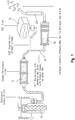
- an exemplary schematic diagram illustrates an inline six cylinder diesel engine 10 with exhaust gas recirculation (EGR) that is utilized to reduce NO x formation.
- EGR works by recirculating a portion of an engine's exhaust gas back to the engine cylinders.
- the exhaust gas replaces some of the excess oxygen in the pre-combustion mixture.
- NO x forms primarily when a mixture of nitrogen and oxygen is subjected to high temperature and NO x formation progresses much faster at high temperatures
- EGR reduces the amount of NO x the combustion generates. Nevertheless, NO x formation is an inherent part of combustion.
- NO x formation has been known to have significant detrimental consequences on our environment. These consequences include acid rain, smog, and creation of harmful particulate matter. In order to combat these consequences, diesel engine manufacturers have implemented technologies to reduce NO x from diesel fuel combustion. One of these technologies involves downstream treatment of the diesel exhaust through selective catalytic reduction (SCR).
- SCR selective catalytic reduction
- SCR uses a urea based diesel exhaust fluid (DEF) and a catalytic converter to significantly reduce oxides of nitrogen (NO x ) emissions.
- DEF diesel exhaust fluid
- Small quantities of diesel exhaust fluid (DEF) are injected into the exhaust upstream of a catalyst, where it vaporizes and decomposes to form ammonia and carbon dioxide.
- Ammonia (NH 3 ) is the desired product, which in conjunction with the SCR catalyst, converts the NO x to harmless nitrogen (N 2 ) and water (H 2 O).
- FIG. 1 shows a common SCR implementation.
- exhaust from the diesel engine 10 is directed through a particulate filter 12 and into a decomposition tube 14.
- DEF a blended aqueous urea solution and deionized water
- a supply tank 16 is injected into communication with the exhaust, which results in the urea decomposing to form ammonia prior to introduction to a catalytic converter 18.
- the catalytic converter 18 the ammonia and NO x components of the exhaust react in the presence of the catalyst to generate water, nitrogen gas, and oxygen gas.
- the water, nitrogen gas, and oxygen gas is thereafter conveyed to the open atmosphere via an exhaust stack or tailpipe 20.
- decomposition tubes are formed by rolling metal sheets to form a circular cross-section tube. Thereafter, the tube is modified to include an injector fitting, commonly by welding the injector fitting over a preexisting opening in the rolled tube.
- an injector fitting commonly by welding the injector fitting over a preexisting opening in the rolled tube.
- an entirely separate mixing structure is positioned within the tube and welded to the interior of the tube. The additional steps of mounting the injector fitting and mixing structure within the rolled tube add considerable cost and time to the overall fabrication process for producing a decomposition tube. At the same time, the welds may sometimes impart localized areas of weakness to the rolled tube that may eventually give way and create unintended orifices within the tube.
- the seams between the welds and the decomposition tube and mixer are subject to attack by urea that flows through the decomposition tube, causing separation between the welds and the decomposition tube and mixer. This separation leads to attachment failure between the mixer and the decomposition tube.
- the exemplary embodiments of the present disclosure include novel decomposition conduits and methods of fabricating these novel conduits.
- the sand core comprises a cylindrical sand body interposed by the static mixer, the cylindrical sand body including a projection representative of an injector adapter of the decomposition conduit housing.
- the act of molding the decomposition conduit includes suspending the sand core at least partially within the decomposition conduit housing mold.
- the static mixer includes a plurality of mixer fins distributed within a metal band having an outer circumferential face and, the act of molding the decomposition conduit housing includes overmolding material into contact with the outer circumferential face of the static mixer, where overmolding the material operates to bond the static mixer to the decomposition conduit housing.
- the method also includes the act of removing the molded decomposition housing from the mold, where at least a portion of the sand core remains within the molded decomposition housing when the decomposition housing is removed from the mold.
- the act of creating the sand core includes forming a cylindrical sand body interposed by the static mixer, the cylindrical sand body including a projection representative of an injector adapter of the decomposition conduit housing.
- the act of creating the sand core includes positioning the static mixer within a sand core mold, wherein the static mixer and the sand core mold cooperate to delineate a sand core cavity.
- the sand core mold includes prongs formed by walls of the sand core mold tapering to seat the static mixer therein.
- the static mixer includes a plurality of mixer fins distributed within a metal band having an outer circumferential face and, the act of molding the decomposition conduit housing includes overmolding material into contact with the outer circumferential face of the static mixer, where overmolding the material operates to bond the static mixer to the decomposition conduit housing.
- the sand core includes a bell and, the act of molding the decomposition conduit housing includes integrally forming the bell.
- the sand core includes a plurality of bells and, the act of molding the decomposition conduit includes integrally forming the plurality of bells.
- the sand core includes a pair of circumferential depressions formed on opposite sides of the static mixer.
- It is a third aspect of the present disclosure to provide a decomposition structure comprising a decomposition conduit including an outer housing defining a flow path between an inlet orifice and an outlet orifice, the decomposition conduit including an integral static mixer in series with the fluid flow path.
- the decomposition conduit includes at least one of a ninety degree elbow section and a straight section.
- the decomposition conduit further includes an integrated injector port.
- the decomposition conduit and the injector port comprise cast metal.
- the static mixer is embedded within the housing of the decomposition conduit.
- the decomposition conduit is at least partially filled with sand.
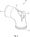
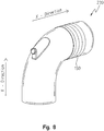
- a first exemplary decomposition conduit 100 includes an inlet bell 102 in communication with an outlet bell 104 via a ninety degree curved elbow or conduit 106.
- the bells 102, 104 are integrally formed with the curved conduit 106 and provide a female interface to accept corresponding male pipes (not shown).
- Fluid flow is adapted to pass through the inlet bell 102 in a Y-direction and be redirected in an X-direction (see FIG. 8 ), approximately perpendicular to the Y-direction, before egressing through the outlet bell 104.
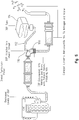
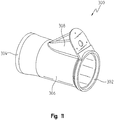
- An injector fitting 108 is integrally formed with the conduit 106 in order to receive an injector 110 (see FIG. 5 ). Any commercially available DEF injectors may be used with the instant decomposition tube 100. In this exemplary embodiment, the injector is received within the injector fitting 108 and mounted thereto in order to direct the DEF fluid coaxially with the exhaust flowing in the X-direction.
- the injector 110 is connected to a DEF supply line 112 in communication with a DEF supply tank 114.
- the DEF tank supplies DEF fluid to the injector 110, where DEF fluid is injected into communication with the exhaust.
- DEF fluid decomposes to form ammonia that is mixed with exhaust prior to reaching a catalytic converter 120 downstream from the decomposition conduit 100.
- additional mixing other than inherently provided by DEF fluid and exhaust being in communication with one another is preferred.
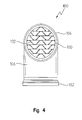
- an in-line static mixer 130 is provided as part of the decomposition conduit 100 downstream from the injector fitting 108 and just upstream from the outlet bell 104.
- the static mixer 130 comprises a series of fixed elements or fins 132 circumscribed by a metal band integrally formed and mounted to the interior wall of the conduit.
- the fixed geometric design of the elements 132 simultaneously produces patterns of flow division and radial mixing. As a result, the ammonia and exhaust are mixed more effectively.
- One of the advantages of a static mixer 130 over a conventional mixer is the absence of moving parts that may be prone to motion stresses and corresponding fatigue failure.
- the static mixer 130 is formed as an integral unit with the curved conduit 106 and the injector fitting 108.
- an exemplary process flow 200 details how the decomposition conduit 100 is fabricated.
- the static mixer core 130 is fabricated. Those skilled in the art are familiar with fabricating static mixer cores 130 bounded by a circular wall.
- the second step 204 is to insert the static mixer core 130 into a sand mold (see FIG. 7 ) in order to form a sand core 230 (see FIG. 8 ).
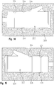
- the sand mold comprises two half sections 240 each having an interior cavity 242 that is exactly one half of the size and includes the same dimensions as the interior of the decomposition conduit 100 to be fabricated.
- Each sand mold half 240 includes an elbow-shaped wall 244 that tapers to include a pair of circumferential projections 246. These circumferential projections 246 operate as boundaries or bookends to help seat the static mixer 130 within the mold.
- the taper of the wall 244 is operative to reduce the cross-section of the sand core 230. As will be discussed hereafter, this reduction in the cross-section of the sand core 230 cooperates with the decomposition mold to create a decomposition conduit with a smooth transition between its interior wall and that of the static mixer 130.
- the mold halves 240 are brought together and closed, followed by the introduction of sand to fill all of the voids on the interior of the mold that are not otherwise occupied by the static mixer core.
- the mold halves 240 are generally constructed of metal, but the mold halves may also be constructed of wood, gypsum or other material having sufficient hardness and strength.
- One exemplary technique to fill the interior of the mold involves blowing a sand-air mixture into the mold to uniformly distribute the sand (with resin) within the mold. Afterwards, the sand is packed within the mold using a combination of vibratory compacting and application of positive pressure using an inflatable bladder or application of negative pressure using a vacuum. The mold is thereafter opened and the resulting sand core 230 is released from the mold halves using gas flow. Specifically, the mold halves include air channels to permit compressed air to flow therethrough and push against the sand core 230 in order to rapidly release the sand core from the mold halves. The mold is then cleaned for reuse and the process starts again to form another sand core. The resulting sand core 230 may be finished by hand or machine to remove certain joint lines left behind by the joining of the mold halves and thereafter heat treated.
- the fourth step 208 includes inserting the sand core 230 is a unitary piece within a decomposition mold (not shown).
- the decomposition mold includes an internal cavity that has the same dimensions as the decomposition conduit 100 to be fabricated, in addition to the interior of the decomposition conduit.
- the sand core 230 is suspended within the decomposition mold and the decomposition mold is closed.
- the resulting cavity within the decomposition mold has the same dimensions as the decomposition conduit 100 to be fabricated.
- molten metal is introduced into the interior of the decomposition mold and fills the gaps between the sand core and mold.
- the result of the fifth step 210 is a cast decomposition conduit housing 100A that is formed around the sand core 230.
- the metal decomposition conduit housing 100A is integrally formed with the static mixer core 130 so that there is no seam or welded interface between the outer circumferential portion of the conduit and the circular rim of the static mixer core 130.
- the term "integral” refers to a single structure that may be comprised of multiple structures without requiring welds or other fastening devices to mount the multiple structures to one another.
- the term “integrally formed” refers to a process where multiple structures are produced to create is a single piece, where the multiple structures are mounted to one another without requiring welds or other fastening devices.
- the incidence of urea degradation causing the static mixer core 130 to separate from the decomposition conduit is substantially reduced if not eliminated.
- the decomposition conduit housing and sand core 230 are processed to remove the sand from the interior of the conduit.
- Exemplary methods of removing the sand include vibrating the sand free, using a fluid to flow through the interior of the decomposition conduit to remove the sand, and immersing the decomposition conduit in a fluid tank. The result of any one or more of these processes is the decomposition conduit shown in FIGS. 2-4 .
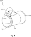
- a second exemplary decomposition conduit 300 includes an inlet bell 302 in communication with an outlet bell 304 interposing a straight conduit 306.
- the bells 302, 304 are integrally formed with the straight conduit 306 and provide a female interface to accept corresponding male pipes (not shown). Fluid flow is adapted to pass through the inlet bell 302 before egressing through the outlet bell 304.
- An injector fitting 308 is integrally formed with the conduit 306 in order to receive an injector 110 (see FIG. 5 ).
- the injector 110 is connected to a DEF supply line 112 in communication with a DEF supply tank 114.
- the DEF tank supplies DEF fluid to the injector 110, where DEF fluid is injected into communication with the exhaust.
- a static mixer 130 is provided as part of the decomposition conduit 300 downstream from the injector fitting 308 and just upstream from the outlet bell 304. Unlike prior art decomposition tubes, the static mixer 130 is formed as an integral unit with the straight conduit 306 and the injector fitting 308.
- the same or similar process flow 200 as described with respect to the first exemplary embodiment 100 may be used to fabricate the second exemplary decomposition conduit 300.
- the second exemplary embodiment includes fabricating a relatively straight sand core 430 using a sand mold 320 having an interior cavity that is exactly the same size and includes the same dimensions as the interior of the decomposition conduit 300 to be fabricated.
- the sand mold 320 has an interior cavity 322 that is exactly the same size and includes the same dimensions as the interior of the decomposition conduit 300 to be fabricated.
- the sand mold 320 includes a wall 324 that tapers to include a pair of circumferential projections 326. These circumferential projections 226 operate as boundaries or bookends to help seat the static mixer 130 within the mold. It should be noted that the taper of the wall 324 is operative to reduce the cross-section of the sand core 430.
- this reduction in the cross-section of the sand core 430 cooperates with the decomposition mold to create a decomposition conduit with a smooth transition between its interior wall and that of the static mixer 130.
- the mold is closed and sand is introduced to fill all of the voids on the interior of the mold that are not otherwise occupied by the static mixer core, thus creating the sand core 430.
- the mold halves 320 are generally constructed of metal, but the mold halves may also be constructed of wood, gypsum or other material having sufficient hardness and strength.
- the straight sand core 430 is thereafter inserted as a unitary piece within a decomposition mold (not shown).
- the decomposition mold includes an internal cavity that has the same dimensions as the decomposition conduit 300 to be fabricated, in addition to the interior of the decomposition conduit.
- the sand core 430 is suspended within the decomposition mold and the decomposition mold is closed.
- the resulting cavity within the decomposition mold has the same dimensions as the decomposition conduit 300 to be fabricated. Thereafter, molten metal is introduced into the interior of the decomposition mold and fills the gaps between the sand core and mold.
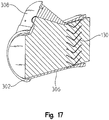
- the result of the casting step is a decomposition conduit housing 300A that is formed around the sand core 430.
- the metal decomposition conduit housing 300A is integrally formed with the static mixer core 130 so that there is no seam or welded interface between the outer circumferential portion of the conduit and the circular rim of the static mixer core 430.
- the incidence of urea degradation causing the static mixer core 130 to separate from the decomposition conduit is substantially reduced if not eliminated.
- the decomposition conduit housing and sand core 430 are processed to remove the sand from the interior of the conduit.
- Exemplary methods of removing the sand include vibrating the sand free, using a fluid to flow through the interior of the decomposition conduit to remove the sand, and immersing the decomposition fluid in a fluid tank. The result of any one or more of these processes is the decomposition conduit 300 shown in FIGS. 10 and 11 .
Landscapes
- Chemical & Material Sciences (AREA)
- Engineering & Computer Science (AREA)
- Chemical Kinetics & Catalysis (AREA)
- Mechanical Engineering (AREA)
- General Engineering & Computer Science (AREA)
- Combustion & Propulsion (AREA)
- Toxicology (AREA)
- Health & Medical Sciences (AREA)
- Dispersion Chemistry (AREA)
- Molds, Cores, And Manufacturing Methods Thereof (AREA)
- Exhaust Silencers (AREA)
- Exhaust Gas After Treatment (AREA)
- Processing And Handling Of Plastics And Other Materials For Molding In General (AREA)
Abstract
Description
- The present disclosure relates to diesel exhaust emissions technology and, more specifically, to a decomposition conduit fabricated with an integrated mixer and methods of manufacturing the same.
- Referring to
FIG. 1 , an exemplary schematic diagram illustrates an inline sixcylinder diesel engine 10 with exhaust gas recirculation (EGR) that is utilized to reduce NOx formation. EGR works by recirculating a portion of an engine's exhaust gas back to the engine cylinders. In a diesel engine, the exhaust gas replaces some of the excess oxygen in the pre-combustion mixture. Because NOx forms primarily when a mixture of nitrogen and oxygen is subjected to high temperature and NOx formation progresses much faster at high temperatures, EGR reduces the amount of NOx the combustion generates. Nevertheless, NOx formation is an inherent part of combustion. - NOx formation has been known to have significant detrimental consequences on our environment. These consequences include acid rain, smog, and creation of harmful particulate matter. In order to combat these consequences, diesel engine manufacturers have implemented technologies to reduce NOx from diesel fuel combustion. One of these technologies involves downstream treatment of the diesel exhaust through selective catalytic reduction (SCR).
- SCR uses a urea based diesel exhaust fluid (DEF) and a catalytic converter to significantly reduce oxides of nitrogen (NOx) emissions. Small quantities of diesel exhaust fluid (DEF) are injected into the exhaust upstream of a catalyst, where it vaporizes and decomposes to form ammonia and carbon dioxide. Ammonia (NH3) is the desired product, which in conjunction with the SCR catalyst, converts the NOx to harmless nitrogen (N2) and water (H2O).
-
FIG. 1 shows a common SCR implementation. In this circumstance, exhaust from thediesel engine 10 is directed through aparticulate filter 12 and into adecomposition tube 14. In thedecomposition tube 14, DEF (a blended aqueous urea solution and deionized water) from asupply tank 16 is injected into communication with the exhaust, which results in the urea decomposing to form ammonia prior to introduction to acatalytic converter 18. Within thecatalytic converter 18, the ammonia and NOx components of the exhaust react in the presence of the catalyst to generate water, nitrogen gas, and oxygen gas. The water, nitrogen gas, and oxygen gas is thereafter conveyed to the open atmosphere via an exhaust stack ortailpipe 20. - As part of a common SCR implementation, decomposition tubes are formed by rolling metal sheets to form a circular cross-section tube. Thereafter, the tube is modified to include an injector fitting, commonly by welding the injector fitting over a preexisting opening in the rolled tube. Likewise, to the extent a mixer is provided with the decomposition tube, an entirely separate mixing structure is positioned within the tube and welded to the interior of the tube. The additional steps of mounting the injector fitting and mixing structure within the rolled tube add considerable cost and time to the overall fabrication process for producing a decomposition tube. At the same time, the welds may sometimes impart localized areas of weakness to the rolled tube that may eventually give way and create unintended orifices within the tube. Moreover, the seams between the welds and the decomposition tube and mixer are subject to attack by urea that flows through the decomposition tube, causing separation between the welds and the decomposition tube and mixer. This separation leads to attachment failure between the mixer and the decomposition tube.
- The exemplary embodiments of the present disclosure include novel decomposition conduits and methods of fabricating these novel conduits.
- It is a first aspect of the present disclosure to provide a method of fabricating a decomposition conduit with an in-line static mixer, the method comprising molding a decomposition conduit housing around a sand core by inserting molding material into a cavity between a decomposition conduit housing mold and the sand core, where the sand core includes a static mixer and, where the act of molding the decomposition conduit housing is operative to mount the static mixer to the molded decomposition conduit housing.
- In a more detailed embodiment of the first aspect, the sand core comprises a cylindrical sand body interposed by the static mixer, the cylindrical sand body including a projection representative of an injector adapter of the decomposition conduit housing. In yet another more detailed embodiment, the act of molding the decomposition conduit includes suspending the sand core at least partially within the decomposition conduit housing mold. In a further detailed embodiment, the static mixer includes a plurality of mixer fins distributed within a metal band having an outer circumferential face and, the act of molding the decomposition conduit housing includes overmolding material into contact with the outer circumferential face of the static mixer, where overmolding the material operates to bond the static mixer to the decomposition conduit housing. In still a further detailed embodiment, the method also includes the act of removing the molded decomposition housing from the mold, where at least a portion of the sand core remains within the molded decomposition housing when the decomposition housing is removed from the mold.
- It is a second aspect of the present disclosure to provide a method of fabricating a decomposition conduit with an in-line static mixer, the method comprising: (a) creating a sand core incorporating a static mixer; (b) inserting the sand core into a mold to create a decomposition conduit cavity; and, (c) molding a decomposition conduit housing around the sand core by inserting molding material into the decomposition conduit cavity, where the act of molding the decomposition conduit housing is operative to mount the static mixer to the molded decomposition conduit housing.
- In a more detailed embodiment of the second aspect, the act of creating the sand core includes forming a cylindrical sand body interposed by the static mixer, the cylindrical sand body including a projection representative of an injector adapter of the decomposition conduit housing. In yet another more detailed embodiment, the act of creating the sand core includes positioning the static mixer within a sand core mold, wherein the static mixer and the sand core mold cooperate to delineate a sand core cavity. In a further detailed embodiment, the sand core mold includes prongs formed by walls of the sand core mold tapering to seat the static mixer therein. In still a further detailed embodiment, the static mixer includes a plurality of mixer fins distributed within a metal band having an outer circumferential face and, the act of molding the decomposition conduit housing includes overmolding material into contact with the outer circumferential face of the static mixer, where overmolding the material operates to bond the static mixer to the decomposition conduit housing. In a more detailed embodiment, the sand core includes a bell and, the act of molding the decomposition conduit housing includes integrally forming the bell. In a more detailed embodiment, the sand core includes a plurality of bells and, the act of molding the decomposition conduit includes integrally forming the plurality of bells. In another more detailed embodiment, the sand core includes a pair of circumferential depressions formed on opposite sides of the static mixer.
- It is a third aspect of the present disclosure to provide a decomposition structure comprising a decomposition conduit including an outer housing defining a flow path between an inlet orifice and an outlet orifice, the decomposition conduit including an integral static mixer in series with the fluid flow path.
- In a more detailed embodiment of the third aspect, the decomposition conduit includes at least one of a ninety degree elbow section and a straight section. In yet another more detailed embodiment, the decomposition conduit further includes an integrated injector port. In a further detailed embodiment, the decomposition conduit and the injector port comprise cast metal. In still a further detailed embodiment, the static mixer is embedded within the housing of the decomposition conduit. In a more detailed embodiment, the decomposition conduit is at least partially filled with sand.
-
-
FIG. 1 is a schematic diagram showing techniques to reduce particulate and nitrogen oxide emissions from combustion engines. -
FIG. 2 is an elevated perspective view from the rear of a first exemplary decomposition conduit fabricated in accordance with the instant disclosure. -
FIG. 3 is a vertical cross-sectional view of the exemplary decomposition conduit ofFIG. 2 . -
FIG. 4 is a frontal view of the exemplary decomposition conduit ofFIG. 2 . -
FIG. 5 is an exemplary schematic diagram showing techniques to reduce particulate and nitrogen oxide emissions from combustion engines that utilize an exemplary decomposition conduit of the instant disclosure. -
FIG. 6 is an exemplary process flow diagram for constructing a decomposition conduit consistent with the instant disclosure. -
FIG. 7 is an elevated perspective view of one half of a sand mold in accordance with the instant disclosure. -
FIG. 8 is an elevated perspective view from the rear of an exemplary sand core utilized to fabricate the exemplary decomposition conduit ofFIG. 2 . -
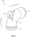
FIG. 9 is an elevated perspective view from the rear of a molded decomposition housing formed over the sand core ofFIG. 8 . -
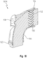
FIG. 10 is an elevated perspective view from the rear of a vertical cross-section showing the molded decomposition housing and sand core ofFIG. 9 . -
FIG. 11 is an elevated perspective view from the rear of a second exemplary decomposition conduit fabricated in accordance with the instant disclosure. -
FIG. 12 is a vertical cross-sectional view of the exemplary decomposition conduit ofFIG. 11 . -
FIG. 13 is an elevated perspective view from the rear of an exemplary sand core utilized to fabricate the exemplary decomposition conduit ofFIG. 11 . -
FIG. 14 is an overhead view of a right side mold half used to fabricate the sand core ofFIG. 13 . -
FIG. 15 is an overhead view of a left side mold half used to fabricate the sand core ofFIG. 13 . -
FIG. 16 is an elevated perspective view from the rear of a vertical cross-section showing the molded decomposition housing and sand core. -
FIG. 17 is a vertical cross-sectional view of the exemplary decomposition conduit housing and sand core ofFIG. 16 . - The exemplary embodiments of the present disclosure are described and illustrated below to encompass decomposition tubes and methods of fabricating decomposition tubes. Of course, it will be apparent to those of ordinary skill in the art that the exemplary embodiments discussed below are merely examples and may be reconfigured without departing from the scope and spirit of the present disclosure. However, for clarity and precision, the exemplary embodiments as discussed below may include optional steps, methods, and features that one of ordinary skill should recognize as not being a requisite to fall within the scope of the present invention.
- Referencing
FIGS. 2-4 , a firstexemplary decomposition conduit 100 includes aninlet bell 102 in communication with anoutlet bell 104 via a ninety degree curved elbow orconduit 106. Thebells curved conduit 106 and provide a female interface to accept corresponding male pipes (not shown). Fluid flow is adapted to pass through theinlet bell 102 in a Y-direction and be redirected in an X-direction (seeFIG. 8 ), approximately perpendicular to the Y-direction, before egressing through theoutlet bell 104. - An injector fitting 108 is integrally formed with the
conduit 106 in order to receive an injector 110 (seeFIG. 5 ). Any commercially available DEF injectors may be used with theinstant decomposition tube 100. In this exemplary embodiment, the injector is received within theinjector fitting 108 and mounted thereto in order to direct the DEF fluid coaxially with the exhaust flowing in the X-direction. - Referring to
FIG. 5 , by way of example, theinjector 110 is connected to aDEF supply line 112 in communication with aDEF supply tank 114. In this manner, the DEF tank supplies DEF fluid to theinjector 110, where DEF fluid is injected into communication with the exhaust. As discussed previously, DEF fluid decomposes to form ammonia that is mixed with exhaust prior to reaching a catalytic converter 120 downstream from thedecomposition conduit 100. But additional mixing other than inherently provided by DEF fluid and exhaust being in communication with one another is preferred. - Referring back to
FIGS. 2-4 , an in-linestatic mixer 130 is provided as part of thedecomposition conduit 100 downstream from theinjector fitting 108 and just upstream from theoutlet bell 104. Thestatic mixer 130 comprises a series of fixed elements orfins 132 circumscribed by a metal band integrally formed and mounted to the interior wall of the conduit. The fixed geometric design of theelements 132 simultaneously produces patterns of flow division and radial mixing. As a result, the ammonia and exhaust are mixed more effectively. One of the advantages of astatic mixer 130 over a conventional mixer is the absence of moving parts that may be prone to motion stresses and corresponding fatigue failure. Unlike prior art decomposition tubes, thestatic mixer 130 is formed as an integral unit with thecurved conduit 106 and theinjector fitting 108. - Referring to
FIG. 6 , anexemplary process flow 200 details how thedecomposition conduit 100 is fabricated. As aninitial step 202, thestatic mixer core 130 is fabricated. Those skilled in the art are familiar with fabricatingstatic mixer cores 130 bounded by a circular wall. After thestatic mixer core 130 is fabricated, thesecond step 204 is to insert thestatic mixer core 130 into a sand mold (seeFIG. 7 ) in order to form a sand core 230 (seeFIG. 8 ). - Referring to
FIGS. 7 and8 , a variety of techniques are employed to carry out thethird step 206 of fabricating thesand core 230, depending on the nature of the mixture, the desired strength of the mold and the type of metal to be cast. In this exemplary embodiment, the sand mold comprises twohalf sections 240 each having aninterior cavity 242 that is exactly one half of the size and includes the same dimensions as the interior of thedecomposition conduit 100 to be fabricated. Eachsand mold half 240 includes an elbow-shapedwall 244 that tapers to include a pair ofcircumferential projections 246. Thesecircumferential projections 246 operate as boundaries or bookends to help seat thestatic mixer 130 within the mold. It should be noted that the taper of thewall 244 is operative to reduce the cross-section of thesand core 230. As will be discussed hereafter, this reduction in the cross-section of thesand core 230 cooperates with the decomposition mold to create a decomposition conduit with a smooth transition between its interior wall and that of thestatic mixer 130. After thestatic mixer core 130 is positioned on the inside of the mold halves 240, the mold halves are brought together and closed, followed by the introduction of sand to fill all of the voids on the interior of the mold that are not otherwise occupied by the static mixer core. The mold halves 240 are generally constructed of metal, but the mold halves may also be constructed of wood, gypsum or other material having sufficient hardness and strength. - One exemplary technique to fill the interior of the mold involves blowing a sand-air mixture into the mold to uniformly distribute the sand (with resin) within the mold. Afterwards, the sand is packed within the mold using a combination of vibratory compacting and application of positive pressure using an inflatable bladder or application of negative pressure using a vacuum. The mold is thereafter opened and the resulting
sand core 230 is released from the mold halves using gas flow. Specifically, the mold halves include air channels to permit compressed air to flow therethrough and push against thesand core 230 in order to rapidly release the sand core from the mold halves. The mold is then cleaned for reuse and the process starts again to form another sand core. The resultingsand core 230 may be finished by hand or machine to remove certain joint lines left behind by the joining of the mold halves and thereafter heat treated. - Referring back to
FIG. 6 , thefourth step 208 includes inserting thesand core 230 is a unitary piece within a decomposition mold (not shown). The decomposition mold includes an internal cavity that has the same dimensions as thedecomposition conduit 100 to be fabricated, in addition to the interior of the decomposition conduit. In exemplary form, thesand core 230 is suspended within the decomposition mold and the decomposition mold is closed. The resulting cavity within the decomposition mold has the same dimensions as thedecomposition conduit 100 to be fabricated. Thereafter, in thefifth step 210, molten metal is introduced into the interior of the decomposition mold and fills the gaps between the sand core and mold. - Referring to
FIGS. 9 and10 , the result of thefifth step 210 is a castdecomposition conduit housing 100A that is formed around thesand core 230. Specifically, the metaldecomposition conduit housing 100A is integrally formed with thestatic mixer core 130 so that there is no seam or welded interface between the outer circumferential portion of the conduit and the circular rim of thestatic mixer core 130. As used herein, the term "integral" refers to a single structure that may be comprised of multiple structures without requiring welds or other fastening devices to mount the multiple structures to one another. As used herein, the term "integrally formed" refers to a process where multiple structures are produced to create is a single piece, where the multiple structures are mounted to one another without requiring welds or other fastening devices. - As will be appreciated by those skilled in the art, by integrating the
static mixer core 130 into the outer wall of thedecomposition conduit 100, the incidence of urea degradation causing thestatic mixer core 130 to separate from the decomposition conduit is substantially reduced if not eliminated. - After the
decomposition conduit housing 100A has been formed in thefifth step 210, the decomposition conduit housing andsand core 230 are processed to remove the sand from the interior of the conduit. Exemplary methods of removing the sand include vibrating the sand free, using a fluid to flow through the interior of the decomposition conduit to remove the sand, and immersing the decomposition conduit in a fluid tank. The result of any one or more of these processes is the decomposition conduit shown inFIGS. 2-4 . - Referring to
FIGS. 11 and12 , a secondexemplary decomposition conduit 300 includes aninlet bell 302 in communication with anoutlet bell 304 interposing astraight conduit 306. Thebells straight conduit 306 and provide a female interface to accept corresponding male pipes (not shown). Fluid flow is adapted to pass through theinlet bell 302 before egressing through theoutlet bell 304. - An injector fitting 308 is integrally formed with the
conduit 306 in order to receive an injector 110 (seeFIG. 5 ). As discussed previously, theinjector 110 is connected to aDEF supply line 112 in communication with aDEF supply tank 114. In this manner, the DEF tank supplies DEF fluid to theinjector 110, where DEF fluid is injected into communication with the exhaust. - Referring back to
FIGS. 11 and12 , astatic mixer 130 is provided as part of thedecomposition conduit 300 downstream from theinjector fitting 308 and just upstream from theoutlet bell 304. Unlike prior art decomposition tubes, thestatic mixer 130 is formed as an integral unit with thestraight conduit 306 and theinjector fitting 308. - Referring to
FIGS. 5 ,12-15 , the same orsimilar process flow 200 as described with respect to the firstexemplary embodiment 100 may be used to fabricate the secondexemplary decomposition conduit 300. However, instead of fabricating acurved sand core 230 as in the first exemplary embodiment, the second exemplary embodiment includes fabricating a relativelystraight sand core 430 using asand mold 320 having an interior cavity that is exactly the same size and includes the same dimensions as the interior of thedecomposition conduit 300 to be fabricated. - Referring to
FIGS. 13-15 , a variety of techniques are employed to carry out thethird step 206 of fabricating thesand core 430, depending on the nature of the mixture, the desired strength of the mold and the type of metal to be cast. In this exemplary embodiment, thesand mold 320 has aninterior cavity 322 that is exactly the same size and includes the same dimensions as the interior of thedecomposition conduit 300 to be fabricated. Thesand mold 320 includes awall 324 that tapers to include a pair ofcircumferential projections 326. These circumferential projections 226 operate as boundaries or bookends to help seat thestatic mixer 130 within the mold. It should be noted that the taper of thewall 324 is operative to reduce the cross-section of thesand core 430. As will be discussed hereafter, this reduction in the cross-section of thesand core 430 cooperates with the decomposition mold to create a decomposition conduit with a smooth transition between its interior wall and that of thestatic mixer 130. After thestatic mixer core 130 is positioned on the inside of themold 320, the mold is closed and sand is introduced to fill all of the voids on the interior of the mold that are not otherwise occupied by the static mixer core, thus creating thesand core 430. The mold halves 320 are generally constructed of metal, but the mold halves may also be constructed of wood, gypsum or other material having sufficient hardness and strength. - The
straight sand core 430 is thereafter inserted as a unitary piece within a decomposition mold (not shown). The decomposition mold includes an internal cavity that has the same dimensions as thedecomposition conduit 300 to be fabricated, in addition to the interior of the decomposition conduit. In exemplary form, thesand core 430 is suspended within the decomposition mold and the decomposition mold is closed. The resulting cavity within the decomposition mold has the same dimensions as thedecomposition conduit 300 to be fabricated. Thereafter, molten metal is introduced into the interior of the decomposition mold and fills the gaps between the sand core and mold. - Referring to
FIGS. 16 and17 , the result of the casting step is adecomposition conduit housing 300A that is formed around thesand core 430. Specifically, the metaldecomposition conduit housing 300A is integrally formed with thestatic mixer core 130 so that there is no seam or welded interface between the outer circumferential portion of the conduit and the circular rim of thestatic mixer core 430. - As will be appreciated by those skilled in the art, by integrating the
static mixer core 130 into the outer wall of thedecomposition conduit 300, the incidence of urea degradation causing thestatic mixer core 130 to separate from the decomposition conduit is substantially reduced if not eliminated. - After the
decomposition conduit housing 300A has been formed, the decomposition conduit housing andsand core 430 are processed to remove the sand from the interior of the conduit. Exemplary methods of removing the sand include vibrating the sand free, using a fluid to flow through the interior of the decomposition conduit to remove the sand, and immersing the decomposition fluid in a fluid tank. The result of any one or more of these processes is thedecomposition conduit 300 shown inFIGS. 10 and11 . - Following from the above description and invention summaries, it should be apparent to those of ordinary skill in the art that, while the methods and apparatuses herein described constitute exemplary embodiments of the present invention, the invention contained herein is not limited to this precise embodiment and that changes may be made to such embodiments without departing from the scope of the invention as defined by the claims. Additionally, it is to be understood that the invention is defined by the claims and it is not intended that any limitations or elements describing the exemplary embodiments set forth herein are to be incorporated into the interpretation of any claim element unless such limitation or element is explicitly stated. Likewise, it is to be understood that it is not necessary to meet any or all of the identified advantages or objects of the invention disclosed herein in order to fall within the scope of any claims, since the invention is defined by the claims and since inherent and/or unforeseen advantages of the present invention may exist even though they may not have been explicitly discussed herein.
Claims (18)
- A method of fabricating a decomposition conduit (100) with an in-line static mixer (130), the method comprising:molding a decomposition conduit housing (100A) around a sand core (230) by inserting molding material into a cavity between a decomposition conduit housing mold (320) and the sand core (230);wherein the sand core (230) includes a static mixer (130); and,wherein the act of molding the decomposition conduit housing (100A) is operative to mount the static mixer (130) to the molded decomposition conduit housing (100A).
- The method of claim 1, wherein the sand core (230) comprises a cylindrical sand body interposed by the static mixer (130), the cylindrical sand body including a projection representative of an injector adapter (108) of the decomposition conduit housing (100A).
- The method of claim 1, wherein the act of molding the decomposition conduit housing (100A) includes suspending the sand core (230) at least partially within the decomposition conduit housing (100A) mold.
- The method of claim 1, wherein:the static mixer (130) includes a plurality of mixer fins (132) distributed within a metal band having an outer circumferential face; and,the act of molding the decomposition conduit housing (100A) includes overmolding material into contact with the outer circumferential face of the static mixer (130), where overmolding the material operates to bond the static mixer (130) to the decomposition conduit housing (100A).
- The method of claim 1, further comprising the act of removing the molded decomposition conduit housing (100A) from the decomposition conduit housing mold (320), where at least a portion of the sand core (230) remains within the molded decomposition conduit housing (100A) when the decomposition conduit housing (100A) is removed from the decomposition conduit housing mold (320).
- The method of claim 1, further comprising the act of inserting the sand core (230) into the decomposition housing mold (320) to create the decomposition conduit cavity and the act of creating the sand core (230) incorporating the static mixer (130).
- The method of claim 6, wherein the act of creating the sand core (230) includes forming a cylindrical sand body interposed by the static mixer (130), the cylindrical sand body including a projection representative of an injector fitting (108) of the decomposition conduit housing (100A).
- The method of claim 6, wherein the act of creating the sand core (230) includes positioning the static mixer (130) within a sand core mold (240), wherein the static mixer (130) and the sand core mold (240) cooperate to delineate a sand core cavity.
- The method of claim 8, wherein the sand core mold (240) includes prongs (246) formed by walls of the sand core mold (240) tapering to seat the static mixer (130) therein.
- The method of claim 6, wherein:the sand core (230) includes a bell (102, 104); and,the act of molding the decomposition conduit housing (100A) includes integrally forming the bell (102, 104).
- The method of claim 6, wherein:the sand core (230) includes a plurality of bells (102, 104); and,the act of molding the decomposition conduit housing (100A) includes integrally forming the plurality of bells (102, 104).
- The method of claim 6, wherein the sand core (230) includes a pair of circumferential depressions formed on opposite sides of the static mixer (130).
- A decomposition structure comprising:a decomposition conduit (100) including an outer housing (100A) defining a fluid flow path between an inlet orifice (102) and an outlet orifice (104), the decomposition conduit (100) including an integral static mixer (130) in series with the fluid flow path.
- The decomposition structure of claim 13, wherein the decomposition conduit (100) includes at least one of a ninety degree elbow section and a straight section.
- The decomposition structure of claim 13, wherein the decomposition conduit (100) further includes an integrated injector port (108).
- The decomposition structure of claim 15, wherein the decomposition conduit (100) and the injector port (108) comprise cast metal.
- The decomposition structure of claim 13, wherein static mixer (130) is embedded within the outer housing (100A) of the decomposition conduit (100).
- The decomposition structure of claim 13, wherein the decomposition conduit (100) is at least partially filled with sand.
Applications Claiming Priority (1)
| Application Number | Priority Date | Filing Date | Title |
|---|---|---|---|
| US13/031,824 US8689854B2 (en) | 2011-02-22 | 2011-02-22 | Decomposition conduit fabrication method |
Publications (2)
| Publication Number | Publication Date |
|---|---|
| EP2492466A2 true EP2492466A2 (en) | 2012-08-29 |
| EP2492466A3 EP2492466A3 (en) | 2013-11-20 |
Family
ID=45607029
Family Applications (1)
| Application Number | Title | Priority Date | Filing Date |
|---|---|---|---|
| EP12154712.9A Withdrawn EP2492466A3 (en) | 2011-02-22 | 2012-02-09 | Decomposition conduit fabrication method |
Country Status (3)
| Country | Link |
|---|---|
| US (1) | US8689854B2 (en) |
| EP (1) | EP2492466A3 (en) |
| JP (1) | JP2012172678A (en) |
Cited By (1)
| Publication number | Priority date | Publication date | Assignee | Title |
|---|---|---|---|---|
| CN109209581A (en) * | 2017-07-04 | 2019-01-15 | 佛吉亚排气系统有限公司 | Injection apparatus and corresponding exhaust line for vehicle exhaust pipeline |
Families Citing this family (4)
| Publication number | Priority date | Publication date | Assignee | Title |
|---|---|---|---|---|
| GB201207201D0 (en) * | 2012-04-24 | 2012-06-06 | Perkins Engines Co Ltd | Emissions cleaning module for a diesel engine |
| US9091193B2 (en) | 2013-12-13 | 2015-07-28 | Cnh Industrial America Llc | Systems and methods for cooling a diesel exhaust fluid dosing module of an agricultural vehicle |
| CN105643216B (en) * | 2016-04-02 | 2018-02-09 | 无锡市蠡园金属容器有限公司 | Static mixer processing technology |
| CN114033918B (en) * | 2021-12-22 | 2025-01-21 | 天津市欧力诺能源技术有限公司 | A urea hydrolysis decomposition device |
Family Cites Families (7)
| Publication number | Priority date | Publication date | Assignee | Title |
|---|---|---|---|---|
| US3729937A (en) * | 1971-12-17 | 1973-05-01 | Gen Motors Corp | Engine exhaust reactor and method of making |
| US5857328A (en) | 1997-11-24 | 1999-01-12 | General Motors Corporation | Exhaust manifold catalytic converter |
| FR2912464B1 (en) | 2007-02-13 | 2009-04-10 | Renault Sas | DUAL-WALL EXHAUST DUCT COMPRISING A DIFFUSION MEANS. |
| JP4397402B2 (en) | 2007-04-20 | 2010-01-13 | 株式会社日本自動車部品総合研究所 | Exhaust purification device |
| DE102007020812B4 (en) | 2007-05-04 | 2010-01-14 | Audi Ag | Apparatus and method for the addition of fluid pollutant-reducing media in an exhaust passage of an internal combustion engine |
| DE102007051510B4 (en) | 2007-10-29 | 2021-02-25 | Emcon Technologies Germany (Augsburg) Gmbh | Assembly for introducing a reducing agent into the exhaust line of an exhaust system of an internal combustion engine |
| US7976788B2 (en) | 2008-10-16 | 2011-07-12 | Cummins Filtration Ip, Inc. | Detachable decomposition reactor with an integral mixer |
-
2011
- 2011-02-22 US US13/031,824 patent/US8689854B2/en active Active
-
2012
- 2012-01-31 JP JP2012018857A patent/JP2012172678A/en active Pending
- 2012-02-09 EP EP12154712.9A patent/EP2492466A3/en not_active Withdrawn
Non-Patent Citations (1)
| Title |
|---|
| None |
Cited By (2)
| Publication number | Priority date | Publication date | Assignee | Title |
|---|---|---|---|---|
| CN109209581A (en) * | 2017-07-04 | 2019-01-15 | 佛吉亚排气系统有限公司 | Injection apparatus and corresponding exhaust line for vehicle exhaust pipeline |
| CN109209581B (en) * | 2017-07-04 | 2021-01-26 | 佛吉亚排气系统有限公司 | Injection device for a vehicle exhaust line and corresponding exhaust line |
Also Published As
| Publication number | Publication date |
|---|---|
| US20120211116A1 (en) | 2012-08-23 |
| JP2012172678A (en) | 2012-09-10 |
| EP2492466A3 (en) | 2013-11-20 |
| US8689854B2 (en) | 2014-04-08 |
Similar Documents
| Publication | Publication Date | Title |
|---|---|---|
| US8689854B2 (en) | Decomposition conduit fabrication method | |
| CN102182533B (en) | Air assisted injector, and injection system and exhaust treatment system incorporating the same | |
| JP5610120B2 (en) | Engine exhaust purification system | |
| KR102000805B1 (en) | Cylinder head with fuel guiding portion | |
| JP2009091982A (en) | Exhaust emission control device | |
| CN104955669A (en) | Filler neck assembly and method for producing same | |
| CN110043399A (en) | The fluid delivery ports of whole inlet manifold | |
| CN102209845A (en) | Internal combustion engine system and particulate filter unit for such an internal combustion engine system | |
| JP5316796B2 (en) | Engine exhaust purification system | |
| CN110043387B (en) | Integrated cylinder head with condensate port | |
| CN110043396B (en) | Integrated cylinder head with exhaust gas recirculation | |
| CN110043386B (en) | Fluid delivery port for unitary cylinder head | |
| JP5456279B2 (en) | Exhaust gas purification system for internal combustion engine | |
| KR101892327B1 (en) | Method of operating an internal combustion engine and an internal combustion engine arrangement | |
| CN102439271A (en) | Fluid mixing system | |
| EP3075978A1 (en) | Exhaust pipe structure | |
| CN110043401B (en) | Integral intake manifold | |
| JP6743285B2 (en) | Reductant supply unit Compact side supply inlet port | |
| JP2017523336A (en) | Catalyst unit, catalyst unit manufacturing method, and exhaust gas catalytic converter | |
| CN113738535B (en) | Ejector of miniature turbojet engine | |
| JP2021053954A (en) | Resin pipe and manufacturing method thereof | |
| CN221610064U (en) | Nozzle for a reducing agent injection system and exhaust line for an internal combustion engine | |
| EP2931496A1 (en) | Air duct for a vehicle and a method for fabricating an air duct | |
| JP4983508B2 (en) | Intake control device for internal combustion engine | |
| CN109424403B (en) | combustion engine system |
Legal Events
| Date | Code | Title | Description |
|---|---|---|---|
| PUAI | Public reference made under article 153(3) epc to a published international application that has entered the european phase |
Free format text: ORIGINAL CODE: 0009012 |
|
| AK | Designated contracting states |
Kind code of ref document: A2 Designated state(s): AL AT BE BG CH CY CZ DE DK EE ES FI FR GB GR HR HU IE IS IT LI LT LU LV MC MK MT NL NO PL PT RO RS SE SI SK SM TR |
|
| AX | Request for extension of the european patent |
Extension state: BA ME |
|
| PUAL | Search report despatched |
Free format text: ORIGINAL CODE: 0009013 |
|
| AK | Designated contracting states |
Kind code of ref document: A3 Designated state(s): AL AT BE BG CH CY CZ DE DK EE ES FI FR GB GR HR HU IE IS IT LI LT LU LV MC MK MT NL NO PL PT RO RS SE SI SK SM TR |
|
| AX | Request for extension of the european patent |
Extension state: BA ME |
|
| RIC1 | Information provided on ipc code assigned before grant |
Ipc: F01N 3/28 20060101AFI20131014BHEP Ipc: F01N 13/18 20100101ALI20131014BHEP Ipc: F01N 3/20 20060101ALI20131014BHEP |
|
| 17P | Request for examination filed |
Effective date: 20140520 |
|
| RBV | Designated contracting states (corrected) |
Designated state(s): AL AT BE BG CH CY CZ DE DK EE ES FI FR GB GR HR HU IE IS IT LI LT LU LV MC MK MT NL NO PL PT RO RS SE SI SK SM TR |
|
| 17Q | First examination report despatched |
Effective date: 20160602 |
|
| GRAP | Despatch of communication of intention to grant a patent |
Free format text: ORIGINAL CODE: EPIDOSNIGR1 |
|
| INTG | Intention to grant announced |
Effective date: 20170222 |
|
| GRAS | Grant fee paid |
Free format text: ORIGINAL CODE: EPIDOSNIGR3 |
|
| STAA | Information on the status of an ep patent application or granted ep patent |
Free format text: STATUS: THE APPLICATION IS DEEMED TO BE WITHDRAWN |
|
| 18D | Application deemed to be withdrawn |
Effective date: 20170705 |