EP2492424B1 - Connection device of a partition wall, in particular partition wall for shower - Google Patents
Connection device of a partition wall, in particular partition wall for shower Download PDFInfo
- Publication number
- EP2492424B1 EP2492424B1 EP12001156.4A EP12001156A EP2492424B1 EP 2492424 B1 EP2492424 B1 EP 2492424B1 EP 12001156 A EP12001156 A EP 12001156A EP 2492424 B1 EP2492424 B1 EP 2492424B1
- Authority
- EP
- European Patent Office
- Prior art keywords
- pane
- hinge
- connecting body
- connection device
- recess
- Prior art date
- Legal status (The legal status is an assumption and is not a legal conclusion. Google has not performed a legal analysis and makes no representation as to the accuracy of the status listed.)
- Active
Links
- 238000005192 partition Methods 0.000 title claims description 32
- 239000000853 adhesive Substances 0.000 claims description 33
- 230000001070 adhesive effect Effects 0.000 claims description 33
- 230000008878 coupling Effects 0.000 claims description 27
- 238000010168 coupling process Methods 0.000 claims description 27
- 238000005859 coupling reaction Methods 0.000 claims description 27
- 238000004519 manufacturing process Methods 0.000 claims description 9
- 238000000034 method Methods 0.000 claims description 4
- 241000252233 Cyprinus carpio Species 0.000 claims 1
- 238000010276 construction Methods 0.000 description 3
- 238000009434 installation Methods 0.000 description 3
- 238000007789 sealing Methods 0.000 description 3
- 150000001875 compounds Chemical class 0.000 description 2
- 239000011521 glass Substances 0.000 description 2
- 238000004026 adhesive bonding Methods 0.000 description 1
- 238000004140 cleaning Methods 0.000 description 1
- 238000005553 drilling Methods 0.000 description 1
- 230000000694 effects Effects 0.000 description 1
- 230000002452 interceptive effect Effects 0.000 description 1
- 238000012423 maintenance Methods 0.000 description 1
- 238000002360 preparation method Methods 0.000 description 1
- 239000000344 soap Substances 0.000 description 1
- 238000003860 storage Methods 0.000 description 1
Images


Classifications
-
- E—FIXED CONSTRUCTIONS
- E05—LOCKS; KEYS; WINDOW OR DOOR FITTINGS; SAFES
- E05D—HINGES OR SUSPENSION DEVICES FOR DOORS, WINDOWS OR WINGS
- E05D5/00—Construction of single parts, e.g. the parts for attachment
- E05D5/02—Parts for attachment, e.g. flaps
- E05D5/0246—Parts for attachment, e.g. flaps for attachment to glass panels
-
- E—FIXED CONSTRUCTIONS
- E05—LOCKS; KEYS; WINDOW OR DOOR FITTINGS; SAFES
- E05D—HINGES OR SUSPENSION DEVICES FOR DOORS, WINDOWS OR WINGS
- E05D11/00—Additional features or accessories of hinges
- E05D11/0054—Covers, e.g. for protection
-
- E—FIXED CONSTRUCTIONS
- E05—LOCKS; KEYS; WINDOW OR DOOR FITTINGS; SAFES
- E05D—HINGES OR SUSPENSION DEVICES FOR DOORS, WINDOWS OR WINGS
- E05D3/00—Hinges with pins
- E05D3/06—Hinges with pins with two or more pins
- E05D3/12—Hinges with pins with two or more pins with two parallel pins and one arm
-
- E—FIXED CONSTRUCTIONS
- E05—LOCKS; KEYS; WINDOW OR DOOR FITTINGS; SAFES
- E05D—HINGES OR SUSPENSION DEVICES FOR DOORS, WINDOWS OR WINGS
- E05D7/00—Hinges or pivots of special construction
- E05D7/12—Hinges or pivots of special construction to allow easy detachment of the hinge from the wing or the frame
-
- E—FIXED CONSTRUCTIONS
- E05—LOCKS; KEYS; WINDOW OR DOOR FITTINGS; SAFES
- E05Y—INDEXING SCHEME ASSOCIATED WITH SUBCLASSES E05D AND E05F, RELATING TO CONSTRUCTION ELEMENTS, ELECTRIC CONTROL, POWER SUPPLY, POWER SIGNAL OR TRANSMISSION, USER INTERFACES, MOUNTING OR COUPLING, DETAILS, ACCESSORIES, AUXILIARY OPERATIONS NOT OTHERWISE PROVIDED FOR, APPLICATION THEREOF
- E05Y2600/00—Mounting or coupling arrangements for elements provided for in this subclass
- E05Y2600/50—Mounting methods; Positioning
- E05Y2600/52—Toolless
- E05Y2600/526—Gluing or cementing
-
- E—FIXED CONSTRUCTIONS
- E05—LOCKS; KEYS; WINDOW OR DOOR FITTINGS; SAFES
- E05Y—INDEXING SCHEME ASSOCIATED WITH SUBCLASSES E05D AND E05F, RELATING TO CONSTRUCTION ELEMENTS, ELECTRIC CONTROL, POWER SUPPLY, POWER SIGNAL OR TRANSMISSION, USER INTERFACES, MOUNTING OR COUPLING, DETAILS, ACCESSORIES, AUXILIARY OPERATIONS NOT OTHERWISE PROVIDED FOR, APPLICATION THEREOF
- E05Y2900/00—Application of doors, windows, wings or fittings thereof
- E05Y2900/10—Application of doors, windows, wings or fittings thereof for buildings or parts thereof
- E05Y2900/114—Application of doors, windows, wings or fittings thereof for buildings or parts thereof for showers
Definitions
- the invention relates to a connecting device of a partition, in particular shower partition, according to the features specified in the preamble of claim 1.
- a modular, multifunctional fitting system for shower enclosures which contains a dovetail-shaped base module and also an additional module.
- the additional module is provided to cover the basic module either completely or only partially and execute as an additional decorative part.
- a connecting device of a trained as a shower partition partition which includes a first disc in the form of a door leaf and a second disc or another component.
- the connecting device is designed as a hinge and contains two connecting bodies which are rotatably coupled by means of a hinge pin and which have connecting bodies in the form of hinge parts with plates.
- the plates are components of the respective hinge part and abut against a surface of the first disc or the second disc.
- On the respective opposite surfaces of the first disc and the second disc cover plates are arranged.
- the hinge parts or plates are connected to the respective opposite cover plate by means of screws, which pass through bores of the first and second disc, in such a way that said discs are clamped between the respective hinge part and the oppositely arranged cover plate.
- the production and assembly require a considerable effort, especially since the holes are to be introduced into the discs and especially during assembly as a result of excessive clamping forces damage to the discs may occur.
- the partition will be factory completed by connecting the discs by means of the hinge, whereby the transport and especially the handling during assembly of the partition on site, for example in a bathroom, is difficult.
- partitions in particular shower partitions with at least one, in particular designed as a glass pane a connection device with other fitting, such as elbow or angle, have, by means of which said first disc with a second disc or another component, such as a room wall or Frame, is connected.
- connection devices are constructed quite differently for the particular application and intended use and contain a variety of different components, whereby a considerable effort for the production and storage is required.
- the assembly and in particular the attachment of the connecting devices with the or the discs or other components associated with a considerable effort and / or difficult handling.
- the connecting devices whether they are hinges or other fittings, a considerable volume of construction and also proves the cleaning, in particular an inner surface of the at least one disc often quite difficult.
- connection of the first pane or door leaf with the second pane or another component should be feasible in a simple manner.
- the method for producing the connection and / or the installation of the partition on site should be facilitated and made possible with simple handling.
- the solution of this task is carried out according to the features specified in claim 1. The invention will be explained in more detail with reference to the specific embodiments shown in the drawings, without any limitation.
- a first inventive embodiment of the connecting device is shown, which is designed as a hinge for coupling a first disc 2 with a second disc 4th
- Fig. 1 shows a section through the connecting device and the two discs 2, 4 in a horizontal plane of the partition wall, wherein the two discs 2, 4 are oriented substantially vertically.
- the partition wall contains two such connecting devices, which are arranged spaced apart in the vertical direction, expedient in the region of the upper end and the lower end of the partition wall.
- the discs 2, 4 are only partially shown and preferably formed as glass panes.
- panes 2, 4 of a shower partition wall wherein the first pane 2 is designed as a door leaf and is pivotable about a substantially vertical pivot axis relative to the second pane 4 by means of the hinge, the second pane 4 being firmly fixed and also vertically aligned a room wall or on the edge of a tub or the floor, in particular a shower room, is arranged or wherein the second disc is also pivotable by means of hinges not shown here.
- a continuous seal 16 is fixed to the vertical longitudinal edge 18 of the second disc 4 and is located on the not recognizable here opposite edge of the first disc 2 as well as in particular on a cap 20 of the hinge and consequently also the hinge region is sealed reliable.
- a further sealing element 40 is provided between the cap 20 and the hinge part and / or connecting body 34 of the door leaf 2.
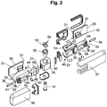
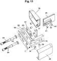
- the various components of the connecting device or the hinge shows the exploded view according to Fig. 2 ,
- the coupling body 32 of the adhesive adapter 26 include a preferably V-shaped recess 42.
- the connecting body 34, 35 triangular or tooth-like projections 44, and Although opposite the formed in particular as a cylinder screws Festlegungs instituten 36.
- With the connecting body 34 is a bearing body 46, preferably integrally connected, which is in particular U-shaped.
- the other connecting body 35 includes a hinge body 48, which engages in the bearing body 46, wherein by means of the guided through an eye 50 of the hinge body 48 bolt 10, which also engages in corresponding holes 51 of the bearing body 46, the hinge connection is completed.
- the hinge includes a lifting mechanism 54 with interlocking and corresponding cam parts provided elements 52, 53 such that upon pivoting of the door this is raised by a predetermined amount, in particular on the order of a few millimeters, preferably of substantially 4 mm.
- the hinge body 48 and the lifting mechanism and / or the elements 52, 53 are surrounded by the cap 20, which has a slot 21 through which an arm 49 of the hinge body 48 and / or the connecting body 35 engages.
- the connecting bodies 34, 35 include holes 39 for receiving molded pins 41 of the caps 37, 38, wherein in the drawing, these pins are shown separately for the sake of simplicity.
- the pins 41 are components of the covers 37, 38 and are fixedly arranged on their inner sides.
- the holes 39 on the one hand and the pins 41 on the other hand are matched to one another and / or adapted to each other, that after placing the cover caps 37, 38, these are fixed on the hinge and overlap and / or enclose the components.
- Fig. 3 the assembly of the connecting device of the hinge or the hinge assembly is shown by means of the adhesive adapter 26 and based on the three superimposed fields shown above, the inventive method for producing the compound by means of the connecting device with the two discs 2, 4 explained in more detail.
- the first pane or the door leaf 2 contains a recess 55, which is preferably formed substantially U-shaped. In the horizontal direction of this recess 55 then the adhesive adapter 26 is provided. In said recess 55, a part of the hinge assembly 56 engages.
- the recess 55 is introduced into the first disc 2. Subsequently, the two adhesive adapters 26 are also glued to the surface or outer surface 22 of the disc 2 and the surface or outer surface 24 of the disc 4 by means of the aforementioned adhesive at the factory.
- the transport of the prepared so far for the preparation of the compound by means of the connecting device partition takes place in the invention with the still separate and not yet interconnected discs 2, 4th
- the disc 4 For installation on site, first the disc 4, for example, mounted in a bathroom, in a vertical orientation and firmly connected with suitable fasteners or the like with a room wall or a frame in a known manner and vertically aligned.
- the assembly 56 which is factory-made and provided for assembly, is connected to the adapter 26 of the second disc 4 in a further method step.
- the coupling body 32 is inserted into the recess 33 of the connecting body 35 and subsequently the fixing and / or permanent connection of the assembly 56 with the disc 4 is carried out by screwing the screw 36.
- the first disc 2 is connected to the assembly 56 and thus with the second disc 4 in the next step.
- the coupling body 32 of the bonded onto the surface 22 adhesive adapter 26 is inserted into the recess 33 of the connecting body 34, and then by means of the fixing element 36, in particular by screwing the associated screw 36, the determination and permanent connection with the connecting body 34 is made.
- the two sub-images show the two disks 2, 4 connected to the assembly 56 and the two adhesive adapters 26.
- the dividing wall analogous to the connecting device produced and arranged in the region of the upper end of the dividing wall or its panes 2, 4 in the region of the lower end, thus vertically spaced, has a further connecting device, which is consistently manufactured and arranged.
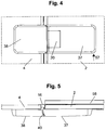
- FIG. 4 and 5 show views of the connecting device, wherein under the covers 37, 38 are the remaining components.
- Fig. 4 shows a view in the direction of the arrow A accordingly Fig .1 .
- Fig. 5 shows a view from above, with a arranged at the lower end of the disc 2 seal 58 can be seen, by means of which in the closed position of the disc formed as a door 2, a seal with respect to a tub rim, a shower room or the like is achieved.
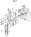
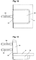
- FIG. 2 shows another embodiment of the connecting device 1 'according to the invention, FIG. which is designed as a wall hinge.
- Fig. 8 shows a view in the direction of arrow B according to Fig. 6 .
- the hinge body 48 is connected via the arm 49 with the connecting body 35 'to an elbow 60.
- the connecting piece 35 ' is formed as a plate and connectable by means of screws 62 and dowels 64 with a wall.
- the hinge body 48 is here arranged at a right angle to the connecting body 35 ', but in the context of the invention, a different angle can also be predetermined.
- the connecting body 35 'of the elbow 60 is substantially formed as a plate and includes holes 66 which have a larger diameter than the associated portions 68 of the screws 62 such that the angle 60 on a wall or the like horizontally and vertically adjustable in the required manner can be arranged and fixed.
- an intermediate plate 61 is arranged, whose bores have a diameter such that the screws 62 pass through with a light play.
- the substantially over the entire height of the partition continuous seal 16 is present, which is fixed by means of a fastening profile 67.
- the fastening profile 67 is partially shown, which contains a recess 69 for the connecting body 35 'and extends like the continuous seal 16 substantially over the entire height of the partition wall.
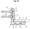
- Fig. 10 to 13 is a trained as a wall angle third, not belonging to the invention embodiment of the connecting device 1 ", wherein Fig. 12 a view in the direction C according to Fig. 10 shows while Fig. 13 shows a view from above.
- the adhesive adapter 26 is connected by means of adhesive 28.
- the coupling body 32 engages in the connecting body 34 and in turn, in particular by means of cylindrical screws 36 fixed.
- the connecting body 34 forms with the connecting body 35 'designed as a plate, an elbow, which is analogous to the second embodiment by means of screws 62 connected to a wall. Also in this embodiment may be different from the illustrated between the connecting body 35 'and the connecting body 34 be given a different angle right angle training. How out Fig.
- the recess 33 of the connecting body 34 in the horizontal direction has a greater length than the coupling body 32 of the adhesive adapter 26.
- the disk connected to the adhesive adapter 26 can be aligned in the horizontal direction with respect to the connecting device 1 " two bores 63, the diameter of which is substantially the same as the outside diameter of the screws 62, such that the screw 62 can be introduced into the bores 63 with a slight clearance.
- the angle piece 60 for example, on a wall, horizontally and vertically aligned and / or can be adjusted.
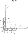
- FIGS. 14 to 17 A fourth, not belonging to the invention embodiment is in the FIGS. 14 to 17 shown, where Fig. 16 a view in the direction of arrow D in Fig. 4 shows while Fig. 17 shows a view from above.
- the disks 2, 4, which in turn are only partially illustrated, are connected to one another at right angles, with the matching adhesive adapters 26 being fixed on the surfaces and / or outer surfaces of the disks 2, 4 by adhesive bonding.
- the connecting bodies 34 are of matching construction and contain interlocking hinge elements 72, 74 which define a common connection axis 70, wherein a defined angular connection can be predetermined in particular by means of screws 76. As can be seen, the two connecting bodies 34, relative to the connecting axis 70, are arranged rotated by 180 ° relative to one another.
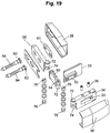
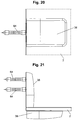
- FIG. 18 to 21 a fifth, not belonging to the invention embodiment of the connecting device, which allows a special angular connection of the disc 2, wherein Fig. 19 a view in the direction of the arrow E according to Fig. 18 shows.
- the adhesive adapter 26 is connected to the pane 2, and furthermore the associated connection body 34 'with the hinge parts 72, 74 is present.
- the connecting body 35 'with hinge parts 72, 74 is provided for attachment to a wall or the like.
- a further coupling body 80 is provided, which likewise has hinge parts 72, 74, which engage in the corresponding and associated hinge parts of the connecting body 34 'or of the connecting body 35', the fixing in turn being effected by means of screws 76.
Landscapes
- Engineering & Computer Science (AREA)
- Mechanical Engineering (AREA)
- Residential Or Office Buildings (AREA)
- Hinges (AREA)
- Securing Of Glass Panes Or The Like (AREA)
Description
Die Erfindung bezieht sich auf eine Verbindungsvorrichtung einer Trennwand, insbesondere Duschtrennwand, gemäß den im Oberbegriff des Patentanspruchs 1 angegebenen Merkmalen.The invention relates to a connecting device of a partition, in particular shower partition, according to the features specified in the preamble of
Aus der
Ferner ist aus der
Des Weiteren ist aus der
Des Weiteren können Trennwände, insbesondere Duschtrennwände mit wenigstens einer, insbesondere als Glasscheibe ausgebildeten Scheibe eine Verbindungsvorrichtung mit einem sonstigen Beschlag, wie Winkelstück oder Winkelverbindung, aufweisen, mittels welcher die genannte erste Scheibe mit einer zweiten Scheibe oder einem weiteren Bauteil, wie beispielsweise einer Raumwand oder Rahmen, verbunden ist. Derartige Verbindungsvorrichtungen sind für den jeweiligen Einsatz und Verwendungszweck recht unterschiedlich aufgebaut und enthalten eine Vielzahl von verschiedenen Bestandteilen, wodurch ein erheblicher Aufwand für die Herstellung und Lagerhaltung erforderlich ist. Des Weiteren ist die Montage und insbesondere die Befestigung der Verbindungsvorrichtungen mit der oder den Scheiben oder weiteren Bauteilen mit einem nicht unerheblichen Aufwand und / oder einer schwierigen Handhabung verbunden. Des Weiteren weisen die Verbindungsvorrichtungen, seien es Scharniere oder sonstige Beschläge, ein nicht unerhebliches Bauvolumen auf und zudem erweist sich die Reinigung, insbesondere einer inneren Oberfläche der wenigstens einen Scheibe oftmals als recht schwierig.Furthermore, partitions, in particular shower partitions with at least one, in particular designed as a glass pane a connection device with other fitting, such as elbow or angle, have, by means of which said first disc with a second disc or another component, such as a room wall or Frame, is connected. Such connection devices are constructed quite differently for the particular application and intended use and contain a variety of different components, whereby a considerable effort for the production and storage is required. Furthermore, the assembly and in particular the attachment of the connecting devices with the or the discs or other components associated with a considerable effort and / or difficult handling. Furthermore, the connecting devices, whether they are hinges or other fittings, a considerable volume of construction and also proves the cleaning, in particular an inner surface of the at least one disc often quite difficult.
Hiervon ausgehend liegt der Erfindung die Aufgabe zugrunde, mit einem geringen konstruktiven Aufwand die aufgezeigten Nachteile zu vermeiden und / oder die Verbindungsvorrichtung dahingehend auszubilden, dass zumindest einige ihrer Bestandteile für unterschiedliche Verwendungen oder Einsatzzwecke benutzt werden können oder mit geringem Aufwand an jene angepasst werden können. Die Verbindungsvorrichtung soll ein geringes Bauvolumen aufweisen und eine einfache Handhabung ermöglichen. Ferner soll die Verbindungsvorrichtung mit geringem Fertigungsaufwand herstellbar sein und / oder einen geringen Montageaufwand zur Herstellung der Verbindung der ersten Scheibe bzw. des Türflügels mit dem weiteren Bauteil bzw. der zweiten Scheibe erfordern. Des Weiteren soll die Verbindungsvorrichtung dahingehend ausgebildet sein, dass nach Art eines Bausatzes oder Systems wesentliche Bestandteile für unterschiedlich ausgebildete Verbindungsvorrichtungen, wie Scharniere oder Wandwinkel verwendet oder zum Einsatz gelangen können. Ferner soll das Verfahren zur Herstellung der Verbindung der ersten Scheibe oder Türflügels mit der zweiten Scheibe oder einem sonstigen Bauteil in einfacher Weise durchführbar sein. Das Verfahren zur Herstellung der Verbindung und / oder der Montage der Trennwand vor Ort soll erleichtert und bei einfacher Handhabung ermöglicht werden.
Die Lösung dieser Aufgabe erfolgt gemäß den im Patentanspruch 1 angegebenen Merkmalen. Die Erfindung wird nachfolgend anhand der in den Zeichnungen dargestellten besonderen Ausführungsbeispiele näher erläutert, ohne dass insoweit eine Beschränkung erfolgt.Proceeding from this, the present invention seeks to avoid the disadvantages shown with a low design effort and / or the connecting device to the effect that at least some of its components can be used for different uses or purposes or can be adapted to those with little effort. The connecting device should have a low volume and allow easy handling. Furthermore, the connecting device should be able to be produced with low production costs and / or require a low installation effort for producing the connection of the first pane or the door leaf with the further component or the second pane. Furthermore, the connecting device should be designed such that, in the manner of a kit or system, essential components for differently designed connecting devices, such as hinges or wall brackets, are provided used or can be used. Furthermore, the method for producing the connection of the first pane or door leaf with the second pane or another component should be feasible in a simple manner. The method for producing the connection and / or the installation of the partition on site should be facilitated and made possible with simple handling.
The solution of this task is carried out according to the features specified in
Es zeigen in schematischen Darstellungen die Verbindungsvorrichtung in Kombination mit einer teilweise dargestellten Trennwand:
- Fig. 1 bis 5
- ein erstes erfindungsgemäßes Ausführungsbeispiel der Verbindungsvorrichtung als Scharnier mit Trennwand und zwei Scheiben,
- Fig. 6 bis 9
- ein zweites erfindungsgemäßes Ausführungsbeispiel der Verbindungsvorrichtung als Wandscharnier mit einer als Türflügel ausgebildeten Scheibe,
- Fig. 10 bis 13
- ein drittes, nicht zur Erfindung gehörendes Ausführungsbeispiel der Verbindungsvorrichtung als Wandwinkel einer feststehenden Scheibe,
- Fig. 14 bis 17
- ein viertes, nicht zur Erfindung gehörendes Ausführungsbeispiel der Verbindungsvorrichtung als vorgebbare definierte Winkelverbindung,
- Fig. 18 bis 21
- ein fünftes, nicht zur Erfindung gehörendes Ausführungsbeispiel der Verbindungsvorrichtung als Winkelstück mit variabel vorgebbarem Winkel einer Scheibe bezüglich einer Wand oder dergleichen.
- Fig. 1 to 5
- a first embodiment according to the invention of the connecting device as a hinge with partition wall and two panes,
- Fig. 6 to 9
- A second embodiment according to the invention of the connecting device as a wall hinge with a disk designed as a door,
- Fig. 10 to 13
- a third, not belonging to the invention embodiment of the connecting device as a wall angle of a fixed disc,
- FIGS. 14 to 17
- A fourth, not belonging to the invention embodiment of the connecting device as a predetermined defined angle connection,
- Fig. 18 to 21
- a fifth, not belonging to the invention embodiment of the connecting device as an angle piece with variably predeterminable angle of a disc with respect to a wall or the like.
In
In der dargestellten Position der ersten Scheibe bzw. des Türflügels 2 wird ein Innenraum 6, insbesondere ein Duschinnenraum, von einem Außenraum 8 abgetrennt. Die Scheibe bzw. der Türflügel 2 kann um einen Scharnierbolzen 10 aus der dargestellten Position sowohl in den Innenraum 6 als auch in den Außenraum 8 jeweils von zumindest näherungsweise 90° zum Freigeben des Durchgangs zwischen dem Innenraum 6 und dem Außenraum 8 geschwenkt werden. Die Scheiben 2, 4 besitzen erste Oberflächen 12, 14, welche in der dargestellten geschlossenen Position der Trennwand und / oder der als Türflügel ausgebildeten Scheibe 2 zweckmäßig im Wesentlichen in der gleichen vertikalen Ebene sich befinden. Insbesondere bei Ausbildung der Trennwand als Duschtrennwand ist es von besonderer Bedeutung, dass die ersten Oberflächen 12, 14 sind die Verbindungsvorrichtung bzw. das Scharnier im Wesentlichen im Außenraum 8 angeordnet und derart ausgebildet sind, dass die ersten Oberflächen 12, 14 Innenflächen der beiden Scheiben 2, 4 bilden und frei zugänglich sind. Zudem ist von besonderer Bedeutung, dass das Scharnier nicht in den Innenraum 6 hineinragt bzw. über die Innenflächen 12, 14 vorsteht. Im Scharnierbereich ist eine durchgehende Dichtung 16 an der vertikalen Längskante 18 der zweiten Scheibe 4 festgelegt und liegt an der hier nicht erkennbaren gegenüberliegenden Kante der ersten Scheibe 2 ebenso an wie insbesondere an einer Kappe 20 des Scharniers und folglich ist auch der Scharnierbereich funktionssicher abgedichtet.In the illustrated position of the first pane or the
An den beiden anderen Oberflächen 22, 24, insbesondere den Außenflächen der beiden Scheiben 2, 4 ist jeweils ein Klebeadapter 26 mit einem Klebemittel 28 durch Verklebung fest verbunden. Die beiden Klebeadapter 26 sind übereinstimmend ausgebildet und enthalten jeweils eine Platte 30 für die Verklebung mit der jeweiligen Oberfläche 22, 24 sowie auf der anderen Seite, abgewandt von den Scheiben 2, 4, einen Kopplungskörper 32. Die Kopplungskörper 32 greifen in eine Ausnehmung 33 eines Verbindungskörpers 34, 35 jeweils ein und enthalten Hinterschneidungen 31 und sind schwalbenschwanzförmig ausgebildet. Zur Festlegung
enthalten die Verbindungskörper 34, 35 Festlegungselemente, insbesondere Zylinderschrauben 36. Des Weiteren sind im Außenraum 8 kappenförmige Abdeckungen 37, 38 vorgesehen, welche die Verbindungskörper 33, 34 einschließlich der jeweiligen Klebeadapter 26 übergreifen. Es sei besonders darauf hingewiesen, dass im Bereich des Innenraums 6 keine über die Innenflächen 12, 14 vorstehende störende Überstände vorhanden sind. Zurweiteren Abdichtung des Scharniers ist ein weiteres Dichtelement 40 zwischen der Kappe 20 und dem Scharnierteil und / oder Verbindungskörper 34 des Türflügels 2 vorgesehen.
Die verschiedenen Bestandteile der Verbindungsvorrichtung bzw. des Scharniers zeigt die Explosionsdarstellung gemäß
zwar gegenüberliegend den insbesondere als Zylinderschrauben ausgebildeten Festlegungselementen 36. Mit dem Verbindungskörper 34 ist ein Lagerkörper 46, bevorzugt einteilig verbunden, welcher insbesondere U-förmig ausgebildet ist. Der andere Verbindungskörper 35 enthält einen Scharnierkörper 48, welcher in den Lagerkörper 46 eingreift, wobei mittels des durch ein Auge 50 des Scharnierkörpers 48 geführten Bolzens 10, welcher gleichfalls in korrespondierende Bohrungen 51 des Lagerkörpers 46 eingreift, die Scharnierverbindung komplettiert ist. Weiterhin enthält das Scharnier eine Anhebemechanik 54 mit ineinander in Eingriff stehenden und korrespondieren Kurventeilen versehenen Elementen 52, 53 derart, dass beim Aufschwenken des Türflügels dieser um einen vorgegebenen Betrag, insbesondere in der Größenordnung einigen Millimetern, bevorzugt von im Wesentlichen 4 mm angehoben wird. Der Scharnierkörper 48 und die Anhebemechanik und / oder die Elemente 52, 53 sind von der Kappe 20 umgeben, welche einen Schlitz 21 aufweist, durch welchen ein Arm 49 des Scharnierkörpers 48 und / oder des Verbindungskörpers 35 greift. Die Verbindungskörper 34, 35 enthalten Bohrungen 39 zur Aufnahme von ausgeformten Stiften 41 der Abdeckkappen 37, 38, wobei in der Zeichnung diese Stifte der Einfachheit halber separat dargestellt sind. Die Stifte 41 sind jedoch Bestandteile der Abdeckungen 37, 38 und sind an deren Innenseiten fest angeordnet. Die Bohrungen 39 einerseits und die Stifte 41 andererseits sind derart aufeinander abgestimmt und / oder aneinander angepasst, dass nach dem Aufsetzen der Abdeckkappen 37, 38 diese auf dem Scharnier fixiert sind und die Bestandteile übergreifen und / oder umschließen.
In
contain the connecting
The various components of the connecting device or the hinge shows the exploded view according to
Although opposite the formed in particular as a cylinder screws
In
Zur Montage vor Ort wird zunächst die Scheibe 4, beispielsweise in einem Badezimmer, in vertikaler Ausrichtung montiert und mit geeigneten Befestigungsmitteln oder dergleichen mit einer Raumwand oder einem Rahmen in bekannter Weise fest verbunden und vertikal ausgerichtet. Wie im oberen Teilbild dargestellt, wird in einem weiteren Verfahrensschritt die Baugruppe 56, welche werksseitig hergestellt und zur Montage bereitgestellt ist, mit dem Adapter 26 der zweiten Scheibe 4 verbunden. Hierbei wird der Kopplungskörper 32 in die Ausnehmung 33 des Verbindungskörpers 35 eingeführt und nachfolgend wird durch Festschrauben der Schraube 36 die Festlegung und / oder dauerhafte Verbindung der Baugruppe 56 mit der Scheibe 4 durchgeführt. Wie im mittleren Teilbild dargestellt, wird im nächsten Verfahrensschritt die erste Scheibe 2 mit der Baugruppe 56 und mithin mit der zweiten Scheibe 4 verbunden. Hierbei wird der Kopplungskörper 32 des auf die Oberfläche 22 aufgeklebten Klebeadapters 26 in die Ausnehmung 33 des Verbindungskörper 34 eingeführt, und daraufhin wird mittels des Festlegungselements 36, insbesondere durch Festschrauben der zugeordneten Schraube 36, die Festlegung und dauerhafte Verbindung mit dem Verbindungskörper 34 hergestellt. Im unteren Teilbild sind nach Durchführung des erfindungsgemäßen Verfahrens die beiden mit der Baugruppe 56 und den beiden Klebeadaptern 26 verbundenen Scheiben 2, 4 dargestellt. Es sei an dieser Stelle angemerkt, dass die Trennwand analog zu der im Bereich des oberen Endes der Trennwand bzw. deren Scheiben 2, 4 gemäß dem erfindungsgemäßen Verfahren hergestellten und angeordneten Verbindungsvorrichtung im Bereich des unteren Endes, somit vertikal beabstandet, eine weitere Verbindungsvorrichtung aufweist, welche übereinstimmend hergestellt und angeordnet ist.For installation on site, first the
In
welches als Wandscharnier ausgebildet ist.
which is designed as a wall hinge.
In
Ein viertes, nicht zur Erfindung gehörendes Ausführungsbeispiel ist in den
Schließlich zeigen
Claims (10)
- A connection device of a partition wall, in particular a shower partition wall which comprises at least one pane (2, 4), comprising a connecting body (34, 35) and a plate (30) connected to the pane (2, 4), wherein an adhesive adapter (26) is provided, which comprises on the one hand the plate (30) and on the other hand a coupling body (32), wherein the plate (30) is connected by means of an adhesive (28) to the pane (2, 4), wherein the connecting body (34, 35) further comprises a recess (33) and the coupling body (32) disposed on the other side of the plate (30) engages into the recess (33) of the connecting body (34, 35) and is fixed in the latter by means of a fixing element (36) constituted as a screw or cylindrical head screw,
characterised in that the coupling body (32) is constituted dove-tailed and comprises at least one V-shaped recess (42) and that, in the recess (33) of the connecting element (34, 35), and more precisely opposite to the fixing element (36), a triangular or tooth-like projection (44) is provided, which engages into the V-shaped recess (42) of the coupling body (32). - The connection device according to claim 1, characterised in that the coupling body (32) comprises two mutually opposite undercuts (31).
- The connection device according to claim 1 or 2, characterised in that a bearing body (46) of a hinge is connected especially in one piece to the connecting body (34) and/or that the bearing body (46) is constituted essentially U-shaped, wherein the bearing body (46) is coupled by means of a hinge bolt (10) to a hinge body (48), which is connected preferably in one piece to another connecting body (35).
- The connection device according to claim 3, characterised in that at least the connecting body (34, 35) and the adhesive adapter (26) are surrounded by a cover (37, 38), which is fixed relative to the connecting body (34, 35) in particular by means of a pin (41) and a hole (39).
- The connection device according to claim 3 or 4, characterised in that the two connecting bodies (34, 35) coupled by means of the bearing body (46) and the hinge body (48) of the hinge form an assembly (56) and that this assembly (56) with the at least one adhesive adapter (26), which is glued onto the surface of the at least one pane (2, 4), can be fixed and/or connected to the assigned pane (2, 4) by introducing the coupling body (32) into the recess (33) of the connecting body (34, 35).
- The connection device according to any one of claims claim 3 to 5, characterised in that the bearing body (46) and the hinge body (48) are disposed inside a carp (20) and/or that a lifting mechanism (54) is assigned to the bearing body (46, 48), by means of which lifting mechanism the pane (2) constituted as a door leaf can be raised in the vertical direction when it is swivelled out of a closed position.
- The connection device according to any one of claims claim 3 to 6, characterised in that the adhesive adapter (26) and the connecting body (34, 35), preferably also the bearing body (46) and the hinge body (48), are disposed inside a covering cap (37, 38), wherein the covering cap (37, 38) is fixed relative to the connecting body (34, 35) preferably by means of at least one pin (41), wherein the at least one pin (41) engages in a corresponding hole (39), in particular of the connecting body (34, 35).
- The connection device according to any one of claims claim 3 to 7, characterised in that the bearing body (46) or the connecting body (34) is disposed at a predetermined angle, in particular of essentially 90°, to the connecting body (35') in an angle piece (60), and/or that the connecting body (35') can be connected to a further component, in particular a room wall or a frame.
- The connection device according to any one of claims claim 3 to 8, characterised in that two connecting bodies (34) are provided, which comprise hinge parts (72, 74) corresponding to one another, wherein the hinge parts (72, 74) of the two connecting bodies (34) engage into one another or, by means of a coupling body (80) which also comprises corresponding hinge parts (72, 74), are connected to one another and define at least one common connecting axis (70).
- A method for producing in a connection by means of a connection device of a partition wall, in particular a shower partition wall which comprises at least one pane (2, 4), comprising a connecting body (34, 35) and a plate (30) connected to the pane (2, 4), wherein an adhesive adapter (26) is provided, which comprises on the one hand the plate (30) and on the other hand a coupling body (32), wherein the plate (30) is connected by means of an adhesive (28) to the pane (2, 4), wherein the connecting body (34, 35) further comprises a recess (33) and the coupling body (32) disposed on the other side of the plate (30) engages into the recess (33) of the connecting body (34, 35) and is fixed in the latter by means of a fixing element (36) constituted as a screw or cylindrical head screw, according to any one of claims 1 to 9, characterised in that the one adhesive adapter (26) is first glued by means of the adhesive (28) onto the pane (2), wherein a second adhesive adapter (26) is also glued onto a second pane (4), that the connecting bodies (34, 35) are completed and prepared to form an assembly (56) constituted as a hinge and that, for an assembly on site, the second pane (4) is first mounted or an angle piece (60) or a further connecting body (35') are connected to a component, the connecting body (35) of the assembly (56) is then fixed on the adhesive adapter (26) in a further process step, and that the pane (2) constituted as a door leaf is then connected to the assembly (56), wherein the coupling body (32) of the adhesive adapter (26) glued onto the pane (2) is introduced into the assigned recess (33) of the connecting body (34) and fixed there.
Applications Claiming Priority (1)
| Application Number | Priority Date | Filing Date | Title |
|---|---|---|---|
| DE202011003134 | 2011-02-23 |
Publications (3)
| Publication Number | Publication Date |
|---|---|
| EP2492424A2 EP2492424A2 (en) | 2012-08-29 |
| EP2492424A3 EP2492424A3 (en) | 2014-10-08 |
| EP2492424B1 true EP2492424B1 (en) | 2016-05-25 |
Family
ID=45655117
Family Applications (1)
| Application Number | Title | Priority Date | Filing Date |
|---|---|---|---|
| EP12001156.4A Active EP2492424B1 (en) | 2011-02-23 | 2012-02-22 | Connection device of a partition wall, in particular partition wall for shower |
Country Status (3)
| Country | Link |
|---|---|
| EP (1) | EP2492424B1 (en) |
| DE (1) | DE202012001745U1 (en) |
| ES (1) | ES2588440T3 (en) |
Families Citing this family (3)
| Publication number | Priority date | Publication date | Assignee | Title |
|---|---|---|---|---|
| EP3181786A1 (en) * | 2015-12-17 | 2017-06-21 | WALA Spolka. z o.o. | Sash hinge member |
| DE202020101419U1 (en) * | 2020-03-13 | 2021-06-15 | Bohle Ag | Cover element for a hinge and a corresponding hinge |
| IT202200019194A1 (en) * | 2022-09-19 | 2024-03-19 | Speedybycasma Srl | HINGE FOR CONNECTING A DOOR, ESPECIALLY A REBOUND DOOR, TO A WALL |
Family Cites Families (5)
| Publication number | Priority date | Publication date | Assignee | Title |
|---|---|---|---|---|
| DE29721037U1 (en) * | 1997-11-28 | 1999-04-22 | Niemann, Hans Dieter, 50169 Kerpen | Door or window hinge |
| DE19960722C2 (en) * | 1999-12-16 | 2002-08-01 | Dorma Gmbh & Co Kg | Adjustable fitting |
| DE20201086U1 (en) | 2002-01-24 | 2002-04-25 | Altura Leiden Holding B.V., Vianen | shower enclosure |
| EP1589170A3 (en) * | 2004-04-20 | 2008-03-19 | Daniel Munch | Modular multifunctional fitting system for shower partitions |
| DE202009002985U1 (en) * | 2009-03-05 | 2010-04-29 | Altura Leiden Holding B.V. | Hinge system for partitions |
-
2012
- 2012-02-22 ES ES12001156.4T patent/ES2588440T3/en active Active
- 2012-02-22 DE DE201220001745 patent/DE202012001745U1/en not_active Expired - Lifetime
- 2012-02-22 EP EP12001156.4A patent/EP2492424B1/en active Active
Also Published As
| Publication number | Publication date |
|---|---|
| EP2492424A2 (en) | 2012-08-29 |
| DE202012001745U1 (en) | 2012-04-03 |
| ES2588440T3 (en) | 2016-11-02 |
| EP2492424A3 (en) | 2014-10-08 |
Similar Documents
| Publication | Publication Date | Title |
|---|---|---|
| DE202013101519U1 (en) | Shower door assembly | |
| DE202004019882U1 (en) | Furniture parts with connecting means | |
| DE2049743B2 (en) | DOOR LOCK | |
| EP1460219A2 (en) | Adapter for a braking device | |
| DD292294A5 (en) | FUEHRUNGSANORDNUNG | |
| DE212015000118U1 (en) | Shower door arrangement and shower door | |
| DE202023102497U1 (en) | Insulating glass element and sauna cabin comprising the insulating glass element | |
| EP2492424B1 (en) | Connection device of a partition wall, in particular partition wall for shower | |
| AT523544B1 (en) | Plastic-metal window system | |
| DE9419959U1 (en) | Device for connecting plastic profiles | |
| EP2107200A2 (en) | Hinge for a door element attached in a pivoting way to a wall element, in particular for shower partition | |
| DE9400647U1 (en) | Fighter connector | |
| DE102012104505B4 (en) | Cross profile, furniture and kit for it | |
| DE29508686U1 (en) | Kit for creating changing rooms, partitions and the like. | |
| EP1038486B1 (en) | Kit for shower partitions | |
| EP2225987B1 (en) | Hinge system for partition walls and method for equipping a hinge system | |
| EP2942462B1 (en) | Fitting for pivotable bearing of a door leaf | |
| DE102005060102A1 (en) | Window or door frame, has metal-cladding profiles positively connected with plastic hollow profiles, where plastic profiles are provided with edges and cladding profiles cover positive profiles at its outer side in partly flat manner | |
| EP3832065B1 (en) | Guide profile for a window or a door with a roller shutter box | |
| EP0371348A1 (en) | Shower partition | |
| DE102015215861A1 (en) | Sun protection device | |
| AT412412B (en) | ADAPTER PROFILE | |
| EP1762691B1 (en) | Seal for a door or window corner | |
| DE8902211U1 (en) | Vertical frame beam of a shower cubicle partition | |
| DE20115426U1 (en) | Kit for a door and door |
Legal Events
| Date | Code | Title | Description |
|---|---|---|---|
| PUAI | Public reference made under article 153(3) epc to a published international application that has entered the european phase |
Free format text: ORIGINAL CODE: 0009012 |
|
| 17P | Request for examination filed |
Effective date: 20120222 |
|
| AK | Designated contracting states |
Kind code of ref document: A2 Designated state(s): AL AT BE BG CH CY CZ DE DK EE ES FI FR GB GR HR HU IE IS IT LI LT LU LV MC MK MT NL NO PL PT RO RS SE SI SK SM TR |
|
| AX | Request for extension of the european patent |
Extension state: BA ME |
|
| PUAL | Search report despatched |
Free format text: ORIGINAL CODE: 0009013 |
|
| AK | Designated contracting states |
Kind code of ref document: A3 Designated state(s): AL AT BE BG CH CY CZ DE DK EE ES FI FR GB GR HR HU IE IS IT LI LT LU LV MC MK MT NL NO PL PT RO RS SE SI SK SM TR |
|
| AX | Request for extension of the european patent |
Extension state: BA ME |
|
| RIC1 | Information provided on ipc code assigned before grant |
Ipc: E05D 7/12 20060101ALI20140901BHEP Ipc: E05D 11/00 20060101ALI20140901BHEP Ipc: E05D 11/10 20060101ALI20140901BHEP Ipc: E05D 3/12 20060101ALI20140901BHEP Ipc: E05D 5/02 20060101AFI20140901BHEP |
|
| 17Q | First examination report despatched |
Effective date: 20141107 |
|
| GRAP | Despatch of communication of intention to grant a patent |
Free format text: ORIGINAL CODE: EPIDOSNIGR1 |
|
| RIC1 | Information provided on ipc code assigned before grant |
Ipc: E05D 5/02 20060101AFI20151124BHEP Ipc: E05D 3/12 20060101ALI20151124BHEP Ipc: E05D 7/12 20060101ALI20151124BHEP Ipc: E05D 11/10 20060101ALI20151124BHEP Ipc: E05D 11/00 20060101ALI20151124BHEP |
|
| INTG | Intention to grant announced |
Effective date: 20151217 |
|
| GRAS | Grant fee paid |
Free format text: ORIGINAL CODE: EPIDOSNIGR3 |
|
| GRAA | (expected) grant |
Free format text: ORIGINAL CODE: 0009210 |
|
| AK | Designated contracting states |
Kind code of ref document: B1 Designated state(s): AL AT BE BG CH CY CZ DE DK EE ES FI FR GB GR HR HU IE IS IT LI LT LU LV MC MK MT NL NO PL PT RO RS SE SI SK SM TR |
|
| REG | Reference to a national code |
Ref country code: GB Ref legal event code: FG4D Free format text: NOT ENGLISH |
|
| REG | Reference to a national code |
Ref country code: CH Ref legal event code: EP |
|
| REG | Reference to a national code |
Ref country code: IE Ref legal event code: FG4D Free format text: LANGUAGE OF EP DOCUMENT: GERMAN Ref country code: AT Ref legal event code: REF Ref document number: 802481 Country of ref document: AT Kind code of ref document: T Effective date: 20160615 |
|
| REG | Reference to a national code |
Ref country code: DE Ref legal event code: R096 Ref document number: 502012007221 Country of ref document: DE |
|
| REG | Reference to a national code |
Ref country code: NL Ref legal event code: FP |
|
| REG | Reference to a national code |
Ref country code: LT Ref legal event code: MG4D |
|
| PG25 | Lapsed in a contracting state [announced via postgrant information from national office to epo] |
Ref country code: FI Free format text: LAPSE BECAUSE OF FAILURE TO SUBMIT A TRANSLATION OF THE DESCRIPTION OR TO PAY THE FEE WITHIN THE PRESCRIBED TIME-LIMIT Effective date: 20160525 Ref country code: LT Free format text: LAPSE BECAUSE OF FAILURE TO SUBMIT A TRANSLATION OF THE DESCRIPTION OR TO PAY THE FEE WITHIN THE PRESCRIBED TIME-LIMIT Effective date: 20160525 Ref country code: NO Free format text: LAPSE BECAUSE OF FAILURE TO SUBMIT A TRANSLATION OF THE DESCRIPTION OR TO PAY THE FEE WITHIN THE PRESCRIBED TIME-LIMIT Effective date: 20160825 |
|
| REG | Reference to a national code |
Ref country code: ES Ref legal event code: FG2A Ref document number: 2588440 Country of ref document: ES Kind code of ref document: T3 Effective date: 20161102 |
|
| PG25 | Lapsed in a contracting state [announced via postgrant information from national office to epo] |
Ref country code: SE Free format text: LAPSE BECAUSE OF FAILURE TO SUBMIT A TRANSLATION OF THE DESCRIPTION OR TO PAY THE FEE WITHIN THE PRESCRIBED TIME-LIMIT Effective date: 20160525 Ref country code: LV Free format text: LAPSE BECAUSE OF FAILURE TO SUBMIT A TRANSLATION OF THE DESCRIPTION OR TO PAY THE FEE WITHIN THE PRESCRIBED TIME-LIMIT Effective date: 20160525 Ref country code: RS Free format text: LAPSE BECAUSE OF FAILURE TO SUBMIT A TRANSLATION OF THE DESCRIPTION OR TO PAY THE FEE WITHIN THE PRESCRIBED TIME-LIMIT Effective date: 20160525 Ref country code: PT Free format text: LAPSE BECAUSE OF FAILURE TO SUBMIT A TRANSLATION OF THE DESCRIPTION OR TO PAY THE FEE WITHIN THE PRESCRIBED TIME-LIMIT Effective date: 20160926 Ref country code: GR Free format text: LAPSE BECAUSE OF FAILURE TO SUBMIT A TRANSLATION OF THE DESCRIPTION OR TO PAY THE FEE WITHIN THE PRESCRIBED TIME-LIMIT Effective date: 20160826 |
|
| PG25 | Lapsed in a contracting state [announced via postgrant information from national office to epo] |
Ref country code: SK Free format text: LAPSE BECAUSE OF FAILURE TO SUBMIT A TRANSLATION OF THE DESCRIPTION OR TO PAY THE FEE WITHIN THE PRESCRIBED TIME-LIMIT Effective date: 20160525 Ref country code: DK Free format text: LAPSE BECAUSE OF FAILURE TO SUBMIT A TRANSLATION OF THE DESCRIPTION OR TO PAY THE FEE WITHIN THE PRESCRIBED TIME-LIMIT Effective date: 20160525 Ref country code: RO Free format text: LAPSE BECAUSE OF FAILURE TO SUBMIT A TRANSLATION OF THE DESCRIPTION OR TO PAY THE FEE WITHIN THE PRESCRIBED TIME-LIMIT Effective date: 20160525 Ref country code: EE Free format text: LAPSE BECAUSE OF FAILURE TO SUBMIT A TRANSLATION OF THE DESCRIPTION OR TO PAY THE FEE WITHIN THE PRESCRIBED TIME-LIMIT Effective date: 20160525 Ref country code: CZ Free format text: LAPSE BECAUSE OF FAILURE TO SUBMIT A TRANSLATION OF THE DESCRIPTION OR TO PAY THE FEE WITHIN THE PRESCRIBED TIME-LIMIT Effective date: 20160525 |
|
| REG | Reference to a national code |
Ref country code: FR Ref legal event code: PLFP Year of fee payment: 6 |
|
| PG25 | Lapsed in a contracting state [announced via postgrant information from national office to epo] |
Ref country code: PL Free format text: LAPSE BECAUSE OF FAILURE TO SUBMIT A TRANSLATION OF THE DESCRIPTION OR TO PAY THE FEE WITHIN THE PRESCRIBED TIME-LIMIT Effective date: 20160525 Ref country code: SM Free format text: LAPSE BECAUSE OF FAILURE TO SUBMIT A TRANSLATION OF THE DESCRIPTION OR TO PAY THE FEE WITHIN THE PRESCRIBED TIME-LIMIT Effective date: 20160525 |
|
| REG | Reference to a national code |
Ref country code: DE Ref legal event code: R097 Ref document number: 502012007221 Country of ref document: DE |
|
| REG | Reference to a national code |
Ref country code: DE Ref legal event code: R082 Ref document number: 502012007221 Country of ref document: DE Representative=s name: REBLE KLOSE SCHMITT PARTNERSCHAFTSGESELLSCHAFT, DE |
|
| PLBE | No opposition filed within time limit |
Free format text: ORIGINAL CODE: 0009261 |
|
| STAA | Information on the status of an ep patent application or granted ep patent |
Free format text: STATUS: NO OPPOSITION FILED WITHIN TIME LIMIT |
|
| 26N | No opposition filed |
Effective date: 20170228 |
|
| PG25 | Lapsed in a contracting state [announced via postgrant information from national office to epo] |
Ref country code: SI Free format text: LAPSE BECAUSE OF FAILURE TO SUBMIT A TRANSLATION OF THE DESCRIPTION OR TO PAY THE FEE WITHIN THE PRESCRIBED TIME-LIMIT Effective date: 20160525 |
|
| REG | Reference to a national code |
Ref country code: IE Ref legal event code: MM4A |
|
| REG | Reference to a national code |
Ref country code: FR Ref legal event code: PLFP Year of fee payment: 7 |
|
| PG25 | Lapsed in a contracting state [announced via postgrant information from national office to epo] |
Ref country code: IE Free format text: LAPSE BECAUSE OF NON-PAYMENT OF DUE FEES Effective date: 20170222 |
|
| PG25 | Lapsed in a contracting state [announced via postgrant information from national office to epo] |
Ref country code: MT Free format text: LAPSE BECAUSE OF FAILURE TO SUBMIT A TRANSLATION OF THE DESCRIPTION OR TO PAY THE FEE WITHIN THE PRESCRIBED TIME-LIMIT Effective date: 20160525 |
|
| PG25 | Lapsed in a contracting state [announced via postgrant information from national office to epo] |
Ref country code: AL Free format text: LAPSE BECAUSE OF FAILURE TO SUBMIT A TRANSLATION OF THE DESCRIPTION OR TO PAY THE FEE WITHIN THE PRESCRIBED TIME-LIMIT Effective date: 20160525 |
|
| PGFP | Annual fee paid to national office [announced via postgrant information from national office to epo] |
Ref country code: NL Payment date: 20190219 Year of fee payment: 8 Ref country code: LU Payment date: 20190219 Year of fee payment: 8 |
|
| PGFP | Annual fee paid to national office [announced via postgrant information from national office to epo] |
Ref country code: IT Payment date: 20181220 Year of fee payment: 13 Ref country code: MC Payment date: 20190218 Year of fee payment: 8 |
|
| PG25 | Lapsed in a contracting state [announced via postgrant information from national office to epo] |
Ref country code: HU Free format text: LAPSE BECAUSE OF FAILURE TO SUBMIT A TRANSLATION OF THE DESCRIPTION OR TO PAY THE FEE WITHIN THE PRESCRIBED TIME-LIMIT; INVALID AB INITIO Effective date: 20120222 |
|
| PG25 | Lapsed in a contracting state [announced via postgrant information from national office to epo] |
Ref country code: BG Free format text: LAPSE BECAUSE OF FAILURE TO SUBMIT A TRANSLATION OF THE DESCRIPTION OR TO PAY THE FEE WITHIN THE PRESCRIBED TIME-LIMIT Effective date: 20160525 |
|
| PG25 | Lapsed in a contracting state [announced via postgrant information from national office to epo] |
Ref country code: CY Free format text: LAPSE BECAUSE OF NON-PAYMENT OF DUE FEES Effective date: 20160525 |
|
| PG25 | Lapsed in a contracting state [announced via postgrant information from national office to epo] |
Ref country code: MK Free format text: LAPSE BECAUSE OF FAILURE TO SUBMIT A TRANSLATION OF THE DESCRIPTION OR TO PAY THE FEE WITHIN THE PRESCRIBED TIME-LIMIT Effective date: 20160525 |
|
| PG25 | Lapsed in a contracting state [announced via postgrant information from national office to epo] |
Ref country code: TR Free format text: LAPSE BECAUSE OF FAILURE TO SUBMIT A TRANSLATION OF THE DESCRIPTION OR TO PAY THE FEE WITHIN THE PRESCRIBED TIME-LIMIT Effective date: 20160525 |
|
| PG25 | Lapsed in a contracting state [announced via postgrant information from national office to epo] |
Ref country code: HR Free format text: LAPSE BECAUSE OF FAILURE TO SUBMIT A TRANSLATION OF THE DESCRIPTION OR TO PAY THE FEE WITHIN THE PRESCRIBED TIME-LIMIT Effective date: 20160525 |
|
| PG25 | Lapsed in a contracting state [announced via postgrant information from national office to epo] |
Ref country code: IS Free format text: LAPSE BECAUSE OF FAILURE TO SUBMIT A TRANSLATION OF THE DESCRIPTION OR TO PAY THE FEE WITHIN THE PRESCRIBED TIME-LIMIT Effective date: 20160925 |
|
| REG | Reference to a national code |
Ref country code: NL Ref legal event code: MM Effective date: 20200301 |
|
| GBPC | Gb: european patent ceased through non-payment of renewal fee |
Effective date: 20200222 |
|
| PG25 | Lapsed in a contracting state [announced via postgrant information from national office to epo] |
Ref country code: MC Free format text: LAPSE BECAUSE OF NON-PAYMENT OF DUE FEES Effective date: 20200302 Ref country code: LU Free format text: LAPSE BECAUSE OF NON-PAYMENT OF DUE FEES Effective date: 20200222 |
|
| PG25 | Lapsed in a contracting state [announced via postgrant information from national office to epo] |
Ref country code: NL Free format text: LAPSE BECAUSE OF NON-PAYMENT OF DUE FEES Effective date: 20200301 |
|
| PG25 | Lapsed in a contracting state [announced via postgrant information from national office to epo] |
Ref country code: GB Free format text: LAPSE BECAUSE OF NON-PAYMENT OF DUE FEES Effective date: 20200222 |
|
| REG | Reference to a national code |
Ref country code: DE Ref legal event code: R081 Ref document number: 502012007221 Country of ref document: DE Owner name: ALTURA LEIDEN HOLDING B.V., NL Free format text: FORMER OWNER: ALTURA LEIDEN HOLDING B.V., VIANEN, NL |
|
| PGFP | Annual fee paid to national office [announced via postgrant information from national office to epo] |
Ref country code: DE Payment date: 20220217 Year of fee payment: 11 Ref country code: AT Payment date: 20220215 Year of fee payment: 11 |
|
| PGFP | Annual fee paid to national office [announced via postgrant information from national office to epo] |
Ref country code: FR Payment date: 20220221 Year of fee payment: 11 Ref country code: ES Payment date: 20220318 Year of fee payment: 11 Ref country code: BE Payment date: 20220216 Year of fee payment: 11 |
|
| REG | Reference to a national code |
Ref country code: DE Ref legal event code: R119 Ref document number: 502012007221 Country of ref document: DE |
|
| REG | Reference to a national code |
Ref country code: AT Ref legal event code: MM01 Ref document number: 802481 Country of ref document: AT Kind code of ref document: T Effective date: 20230222 |
|
| REG | Reference to a national code |
Ref country code: BE Ref legal event code: MM Effective date: 20230228 |
|
| PG25 | Lapsed in a contracting state [announced via postgrant information from national office to epo] |
Ref country code: AT Free format text: LAPSE BECAUSE OF NON-PAYMENT OF DUE FEES Effective date: 20230222 |
|
| PG25 | Lapsed in a contracting state [announced via postgrant information from national office to epo] |
Ref country code: IT Free format text: LAPSE BECAUSE OF NON-PAYMENT OF DUE FEES Effective date: 20230222 Ref country code: FR Free format text: LAPSE BECAUSE OF NON-PAYMENT OF DUE FEES Effective date: 20230228 Ref country code: DE Free format text: LAPSE BECAUSE OF NON-PAYMENT OF DUE FEES Effective date: 20230901 |
|
| PG25 | Lapsed in a contracting state [announced via postgrant information from national office to epo] |
Ref country code: BE Free format text: LAPSE BECAUSE OF NON-PAYMENT OF DUE FEES Effective date: 20230228 |
|
| REG | Reference to a national code |
Ref country code: ES Ref legal event code: FD2A Effective date: 20240405 |
|
| PG25 | Lapsed in a contracting state [announced via postgrant information from national office to epo] |
Ref country code: ES Free format text: LAPSE BECAUSE OF NON-PAYMENT OF DUE FEES Effective date: 20230223 |
|
| PG25 | Lapsed in a contracting state [announced via postgrant information from national office to epo] |
Ref country code: ES Free format text: LAPSE BECAUSE OF NON-PAYMENT OF DUE FEES Effective date: 20230223 |
|
| PGFP | Annual fee paid to national office [announced via postgrant information from national office to epo] |
Ref country code: CH Payment date: 20250301 Year of fee payment: 14 |