EP2492227A2 - Method and apparatus for diverting signatures in a folder - Google Patents
Method and apparatus for diverting signatures in a folder Download PDFInfo
- Publication number
- EP2492227A2 EP2492227A2 EP12156429A EP12156429A EP2492227A2 EP 2492227 A2 EP2492227 A2 EP 2492227A2 EP 12156429 A EP12156429 A EP 12156429A EP 12156429 A EP12156429 A EP 12156429A EP 2492227 A2 EP2492227 A2 EP 2492227A2
- Authority
- EP
- European Patent Office
- Prior art keywords
- guide rollers
- transport
- eccentric
- signatures
- downstream
- Prior art date
- Legal status (The legal status is an assumption and is not a legal conclusion. Google has not performed a legal analysis and makes no representation as to the accuracy of the status listed.)
- Granted
Links
- 238000000034 method Methods 0.000 title claims description 9
- 238000013459 approach Methods 0.000 description 2
- 230000003993 interaction Effects 0.000 description 1
- 238000012986 modification Methods 0.000 description 1
- 230000004048 modification Effects 0.000 description 1
- 238000011144 upstream manufacturing Methods 0.000 description 1
Images


Classifications
-
- B—PERFORMING OPERATIONS; TRANSPORTING
- B65—CONVEYING; PACKING; STORING; HANDLING THIN OR FILAMENTARY MATERIAL
- B65H—HANDLING THIN OR FILAMENTARY MATERIAL, e.g. SHEETS, WEBS, CABLES
- B65H29/00—Delivering or advancing articles from machines; Advancing articles to or into piles
- B65H29/58—Article switches or diverters
-
- B—PERFORMING OPERATIONS; TRANSPORTING
- B65—CONVEYING; PACKING; STORING; HANDLING THIN OR FILAMENTARY MATERIAL
- B65H—HANDLING THIN OR FILAMENTARY MATERIAL, e.g. SHEETS, WEBS, CABLES
- B65H29/00—Delivering or advancing articles from machines; Advancing articles to or into piles
- B65H29/12—Delivering or advancing articles from machines; Advancing articles to or into piles by means of the nip between two, or between two sets of, moving tapes or bands or rollers
-
- B—PERFORMING OPERATIONS; TRANSPORTING
- B65—CONVEYING; PACKING; STORING; HANDLING THIN OR FILAMENTARY MATERIAL
- B65H—HANDLING THIN OR FILAMENTARY MATERIAL, e.g. SHEETS, WEBS, CABLES
- B65H5/00—Feeding articles separated from piles; Feeding articles to machines
- B65H5/36—Article guides or smoothers, e.g. movable in operation
-
- B—PERFORMING OPERATIONS; TRANSPORTING
- B65—CONVEYING; PACKING; STORING; HANDLING THIN OR FILAMENTARY MATERIAL
- B65H—HANDLING THIN OR FILAMENTARY MATERIAL, e.g. SHEETS, WEBS, CABLES
- B65H2301/00—Handling processes for sheets or webs
- B65H2301/30—Orientation, displacement, position of the handled material
- B65H2301/34—Modifying, selecting, changing direction of displacement
-
- B—PERFORMING OPERATIONS; TRANSPORTING
- B65—CONVEYING; PACKING; STORING; HANDLING THIN OR FILAMENTARY MATERIAL
- B65H—HANDLING THIN OR FILAMENTARY MATERIAL, e.g. SHEETS, WEBS, CABLES
- B65H2301/00—Handling processes for sheets or webs
- B65H2301/30—Orientation, displacement, position of the handled material
- B65H2301/34—Modifying, selecting, changing direction of displacement
- B65H2301/342—Modifying, selecting, changing direction of displacement with change of plane of displacement
-
- B—PERFORMING OPERATIONS; TRANSPORTING
- B65—CONVEYING; PACKING; STORING; HANDLING THIN OR FILAMENTARY MATERIAL
- B65H—HANDLING THIN OR FILAMENTARY MATERIAL, e.g. SHEETS, WEBS, CABLES
- B65H2301/00—Handling processes for sheets or webs
- B65H2301/30—Orientation, displacement, position of the handled material
- B65H2301/34—Modifying, selecting, changing direction of displacement
- B65H2301/342—Modifying, selecting, changing direction of displacement with change of plane of displacement
- B65H2301/3422—Modifying, selecting, changing direction of displacement with change of plane of displacement by travelling a path section in arc of circle
-
- B—PERFORMING OPERATIONS; TRANSPORTING
- B65—CONVEYING; PACKING; STORING; HANDLING THIN OR FILAMENTARY MATERIAL
- B65H—HANDLING THIN OR FILAMENTARY MATERIAL, e.g. SHEETS, WEBS, CABLES
- B65H2301/00—Handling processes for sheets or webs
- B65H2301/40—Type of handling process
- B65H2301/44—Moving, forwarding, guiding material
- B65H2301/445—Moving, forwarding, guiding material stream of articles separated from each other
- B65H2301/4455—Diverting a main stream into part streams
- B65H2301/44552—Diverting a main stream into part streams by alternatively directing articles following each other to appropriate part stream
-
- B—PERFORMING OPERATIONS; TRANSPORTING
- B65—CONVEYING; PACKING; STORING; HANDLING THIN OR FILAMENTARY MATERIAL
- B65H—HANDLING THIN OR FILAMENTARY MATERIAL, e.g. SHEETS, WEBS, CABLES
- B65H2404/00—Parts for transporting or guiding the handled material
- B65H2404/10—Rollers
- B65H2404/14—Roller pairs
- B65H2404/141—Roller pairs with particular shape of cross profile
- B65H2404/1414—Roller pairs with particular shape of cross profile complementary relief
-
- B—PERFORMING OPERATIONS; TRANSPORTING
- B65—CONVEYING; PACKING; STORING; HANDLING THIN OR FILAMENTARY MATERIAL
- B65H—HANDLING THIN OR FILAMENTARY MATERIAL, e.g. SHEETS, WEBS, CABLES
- B65H2404/00—Parts for transporting or guiding the handled material
- B65H2404/10—Rollers
- B65H2404/14—Roller pairs
- B65H2404/141—Roller pairs with particular shape of cross profile
- B65H2404/1415—Roller pairs with particular shape of cross profile with male / female profiles
-
- B—PERFORMING OPERATIONS; TRANSPORTING
- B65—CONVEYING; PACKING; STORING; HANDLING THIN OR FILAMENTARY MATERIAL
- B65H—HANDLING THIN OR FILAMENTARY MATERIAL, e.g. SHEETS, WEBS, CABLES
- B65H2404/00—Parts for transporting or guiding the handled material
- B65H2404/60—Other elements in face contact with handled material
- B65H2404/63—Oscillating, pivoting around an axis parallel to face of material, e.g. diverting means
-
- B—PERFORMING OPERATIONS; TRANSPORTING
- B65—CONVEYING; PACKING; STORING; HANDLING THIN OR FILAMENTARY MATERIAL
- B65H—HANDLING THIN OR FILAMENTARY MATERIAL, e.g. SHEETS, WEBS, CABLES
- B65H2404/00—Parts for transporting or guiding the handled material
- B65H2404/60—Other elements in face contact with handled material
- B65H2404/63—Oscillating, pivoting around an axis parallel to face of material, e.g. diverting means
- B65H2404/632—Wedge member
-
- B—PERFORMING OPERATIONS; TRANSPORTING
- B65—CONVEYING; PACKING; STORING; HANDLING THIN OR FILAMENTARY MATERIAL
- B65H—HANDLING THIN OR FILAMENTARY MATERIAL, e.g. SHEETS, WEBS, CABLES
- B65H2404/00—Parts for transporting or guiding the handled material
- B65H2404/70—Other elements in edge contact with handled material, e.g. registering, orientating, guiding devices
- B65H2404/74—Guiding means
-
- B—PERFORMING OPERATIONS; TRANSPORTING
- B65—CONVEYING; PACKING; STORING; HANDLING THIN OR FILAMENTARY MATERIAL
- B65H—HANDLING THIN OR FILAMENTARY MATERIAL, e.g. SHEETS, WEBS, CABLES
- B65H2404/00—Parts for transporting or guiding the handled material
- B65H2404/70—Other elements in edge contact with handled material, e.g. registering, orientating, guiding devices
- B65H2404/74—Guiding means
- B65H2404/741—Guiding means movable in operation
-
- B—PERFORMING OPERATIONS; TRANSPORTING
- B65—CONVEYING; PACKING; STORING; HANDLING THIN OR FILAMENTARY MATERIAL
- B65H—HANDLING THIN OR FILAMENTARY MATERIAL, e.g. SHEETS, WEBS, CABLES
- B65H2404/00—Parts for transporting or guiding the handled material
- B65H2404/70—Other elements in edge contact with handled material, e.g. registering, orientating, guiding devices
- B65H2404/74—Guiding means
- B65H2404/741—Guiding means movable in operation
- B65H2404/7414—Guiding means movable in operation pivotable
-
- B—PERFORMING OPERATIONS; TRANSPORTING
- B65—CONVEYING; PACKING; STORING; HANDLING THIN OR FILAMENTARY MATERIAL
- B65H—HANDLING THIN OR FILAMENTARY MATERIAL, e.g. SHEETS, WEBS, CABLES
- B65H2801/00—Application field
- B65H2801/03—Image reproduction devices
- B65H2801/21—Industrial-size printers, e.g. rotary printing press
Definitions
- This application relates to the field of printing presses, and in particular to the folders for printing presses.
- a web or webs may be printed in various printing units.
- the webs may then be folded and cut into signatures by a folder. It is often desirable to divide the signatures into two product streams for further processing.
- U.S. Patent No. 4,729,282 discusses a sheet diverter, adapted for cooperative association with a cutter in a pinless folder.
- a stationary triangular diverter deflects signatures into one of two guide paths.
- An oscillating diverter guide member composed of a pair of diverter rolls forming a nip, guide the signatures to one side or the other of the triangular diverter.
- the diverter rolls are described as counter-rotating eccentric rolls which create a linear reciprocation of the nip defined by the two rolls.
- U.S. Patent No. 4,373,713 discusses a diverter mechanism which includes a stationary, substantially triangular diverter which deflects signatures into one of two guide paths.
- a pair of guide rolls each have a raised cam portion and a recessed portion which cooperate to guide signatures to one side or the other of the stationary diverter.
- U.S. Patent No. 5,467,976 discusses a diverter mechanism in which includes diverting tapes which are diverted from a position along a horizontal transport path to a position along an inclined transport path, and vice versa, by levers which are swivelably mounted on stationary axes.
- an apparatus for transporting signatures comprises a moving transport surface for transporting signatures; a pair of eccentric guide rollers, rotatable about respective axes, the pair of guide rollers positioned opposite one another to receive signatures therebetween from the moving transport surface; and a diverter positioned downstream of the guide rollers.
- the diverter is movable between a first position to divert signatures received from the guide rollers to a first downstream moving transport surface and a second position to divert signatures received from the guide rollers to a second downstream moving transport surface.
- Each of the eccentric guide rollers may include a first outer circumferential surface having an eccentric protrusion and a second outer circumferential surface recessed relative to the first outer circumferential surface.
- the eccentric protrusion may be tapered from a first height to a second height, greater than the first height.
- the eccentric guide rollers may be positioned such that, as the guide rollers rotate, the first outer circumferential surface of one guide roller faces the second outer circumferential surface of the other guide roller.
- the eccentric guide rollers may also include a plurality of lobes, where each of the lobes is separated from an adjacent lobe by a space, and where each of the plurality of lobes including a first outer circumferential surface having an eccentric protrusion and a second outer circumferential surface recessed relative to the first outer circumferential surface, the eccentric protrusion being tapered from a first height to a second height.
- the diverter may be substantially triangular in shape, and may include a plurality of substantially triangular extensions having spaces therebetween, the spaces aligned with the plurality of lobes.
- the moving transport surface may include a plurality of first transport tapes and a plurality of second transport tapes transporting signatures therebetween.
- the plurality of first transport tapes may pass through the spaces in one of the eccentric guide rollers and the plurality of second transport tapes may pass through spaces in the other eccentric guide roller.
- a plurality of third transport tapes and a plurality of fourth transport tapes may also be provided downstream of the diverter.
- the plurality of first transport tapes and the plurality of third transport tapes may form the first downstream moving transport surface, and the plurality of second transport tapes and the plurality of fourth transport tapes may form the second downstream moving transport surface.
- a method for transporting signatures comprises moving signatures along a common transport path; rotating a pair of eccentric guide rollers, about respective axes, the pair of guide rollers positioned opposite one another to receive signatures therebetween from the common transport path; and moving a diverter positioned downstream of the guide rollers between a first position to divert signatures received from the guide rollers to a first downstream transport path and a second position to divert signatures received from the guide rollers to a second downstream transport path.
- the diverter and guide rollers may be constructed in the manner described above.
- the common transport path may be comprised of the moving transport surface
- the first and second downstream transport paths may be comprised of the first and second downstream moving transport surfaces, as described above.
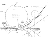
- Figure 1 shows a diverter mechanism just prior to diverting a signature to an upper signature stream
- Fig. 2 shows shows the diverter mechanism of Figure 1 just prior to diverting a subsequent signature to a lower signature stream
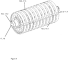
- Figure 3 shows an exemplary pair of eccentric rollers and a diverter of Figures 1 and 2 in perspective view
- Figure 4 shows an eccentric roller of Figure 3 ;
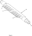
- Figure 5 shows the diverter of Figure 3 .
- a preferred embodiment of the present invention described below in connection with the drawings which illustrate a diverter mechanism 100 which includes a moving transport surface (such as opposed tapes 20, 22) for transporting signatures, a pair of eccentric guide rollers (such as eccentric rollers 10, 11), rotatable about respective axes (such as axes 16, 17), and a diverter (such as diverter 30) positioned downstream of the guide rollers, a first downstream moving transport surface (such as opposed tapes 22, 23) and a second downstream moving transport surface (such as opposed tapes 20, 21).
- a moving transport surface such as opposed tapes 20, 22
- eccentric guide rollers such as eccentric rollers 10, 11
- rotatable about respective axes such as axes 16, 17
- diverter such as diverter 30
- Figures 1 through 5 show the diverter mechanism 100 for splitting a stream of signatures 15 into an upper stream and a lower stream.
- Figure 1 shows the diverter mechanism 100 just prior to diverting a signature 15 to an upper signature stream traveling between tapes 22, 23, and
- Figure 2 shows the diverter mechanism 100 just prior to diverting a subsequent signature 15' to a lower signature stream traveling between tapes 20, 21.
- signatures 15 enter the diverting mechanism via a plurality of first transport tapes 20 and an opposing plurality of second transport tapes 22, moving in the direction 1.
- the signatures are then diverted by the diverter mechanism 100 to either an upper signature stream under the control of opposing tapes 22, 23, or to a lower signature stream under the control of opposing tapes 20, 21.
- the diverter mechanism includes a pair of rotating eccentric guide rolls 10, 11 and a diverter 30.
- Rotating eccentric guide roll 10 has a plurality of axially arranged lobes 10.1, and is mounted for counterclockwise rotation about axis 16, and identical rotating eccentric guide roll 11 has a plurality of axially arranged lobes 11.1 is eccentrically mounted for clockwise rotation about axis 17.
- Figure 3 which illustrates a perspective view of the rolls 10, 11, and diverter 30, with three lobes 10.1 omitted to better view diverter 30, and in Figure 4 which shows a roll 10 or 11 with its drive axis 16 or 17.
- Lobes 10.1 include a circular recessed portion 10.5 and a protruding eccentric portion 10.3.
- the eccentric portion 11.3 is tapered from a maximum protrusion 10.4 to a minimum protrusion 10.2.
- Each of the second transport tapes 22 passes through a space between adjacent lobes 10.1. These spaces are shown in Figures 3 and 4 .
- lobes 11.1 include a circular recessed portion 11.5 and a protruding eccentric portion 11.3, the eccentric portion 11.3 is tapered from a maximum protrusion 11.4 to a minimum protrusion 11.2.
- Each of the first transport tapes 20 passes through a space between adjacent lobes 11.1.
- Tapes 22 travel from roller 60 to guide roll 10, which deflects it to roller 40 of the upper signature stream path.
- Tapes 23 travel around roller 50 and are deflected by roller 40, at which point tapes 22, 23 travel in the direction 1.1 with signatures secured between them.
- Tapes 20 travel from roller 61 to guide roll 11, which deflects them to roller 41 of the lower signature stream path.
- Tapes 21 travel around roller 51 and are deflected by roller 41, at which point tapes 20, 21 travel in the direction 1.2 with signatures secured between them.
- Diverter 30 illustrated in Figures 1 , 2 , 3 , and 5 , is positioned immediately downstream of the guide rolls 10, 11, and is rotatable about axis 35 between a first position, shown in Figure 1 , to guide a signature to the upper signature stream, and a second position, shown in Figure 2 , to guide a signature to the lower signature stream.
- diverter 30 has a plurality of substantially triangular extensions 31 separated by adjacent recesses 32. As shown in Figures 1 , 2 , and 3 , the extensions 31 are positioned so that they can be received in the spaces between adjacent lobes 10.1, 11.1.
- the diverter mechanism 100 is illustrated in position to divert a signature 15 to the upper signature stream path in direction 1.1.
- Diverter 30 is in its first position, with it is extensions 31 closer to lobes 11.1.
- the eccentric protrusion 11.3 of eccentric guide roll 11 in combination with the recessed portion 10.5 of eccentric guide roll 10, leads the signature to an upper signature stream path side of the extensions 31.
- the eccentric rolls 10, 11 continue to rotate, the increasing height of the protrusion 11.3 as it rotates from its minimum 11.2 towards its maximum 11.4, in combination with the recessed portion 10.5 of the lobes 10.1, continues to lead the signature to the upper signature stream path.
- the diverter mechanism 100 is shown in position to divert a subsequent signature 15' to the lower signature stream path in direction 1.2.
- Diverter 30 is now in its second position, with it is extensions 31 closer to lobes 10.1.
- the tail 15.2 of the prior signature 15 is on the upper stream path side of the extensions 31, and the protrusions 11.3 of the lobes 11.1 are downstream of the tips of the extensions 31.
- the eccentric protrusion 10.3 of eccentric guide roll 10 in combination with the recessed portion 11.5 of eccentric guide roll 11, leads the signature to a lower signature stream path side of the extensions 31.
- the eccentric rolls 10, 11 continue to rotate, the increasing height of the protrusion 10.3 as it rotates from its minimum 10.2 towards its maximum 10.4, in combination with the recessed portion 11.5 of the lobes 11.1, continues to lead the signature to the lower signature stream path.
- the diverter mechanism 100 may be driven by one or more motors.
- a single motor could be provided to drive eccentric rolls 10, 11 and diverter 30.
- the rolls 10 and 11 could be driven in common by a motor through a gear train, and a cam could also be driven by the motor with the movement of the diverter being controlled by the interaction of the cam and a cam follower.
- the diverter 30 could be driven by a separate motor.
- Transport tapes 20, 21, 22, and 23 may be driven by the same motor as the rolls 10, 11 and/or diverter, or by one or more other motors. Other drive arrangements could also be provided. In order to divert every signature (i.e.
- the eccentric rolls 10, 11 rotate at 2 time the speed of the signatures, such that two signatures pass through the diverter for every revolution of the rolls 10,11.
- the diverter changes position for each signature.
- the eccentric rolls 10, 11 may rotate at from 1 to 1.5 times the speed of the signatures, and the diverter changes position for every other signature.
- the invention can also have one or more of the following features:
- the moving transport surface comprises a plurality of first transport tapes and a plurality of second transport tapes transporting signatures therebetween, the plurality of first transport tapes passing through the spaces in one of the eccentric guide rollers, the plurality of second transport tapes passing through spaces in the other eccentric guide roller.
- An apparatus for transporting signatures comprising:
Landscapes
- Engineering & Computer Science (AREA)
- Mechanical Engineering (AREA)
- Separation, Sorting, Adjustment, Or Bending Of Sheets To Be Conveyed (AREA)
Abstract
Description
- This application relates to the field of printing presses, and in particular to the folders for printing presses.
- In a web printing press, a web or webs may be printed in various printing units. The webs may then be folded and cut into signatures by a folder. It is often desirable to divide the signatures into two product streams for further processing.
-
U.S. Patent No. 4,729,282 discusses a sheet diverter, adapted for cooperative association with a cutter in a pinless folder. A stationary triangular diverter deflects signatures into one of two guide paths. An oscillating diverter guide member, composed of a pair of diverter rolls forming a nip, guide the signatures to one side or the other of the triangular diverter. The diverter rolls are described as counter-rotating eccentric rolls which create a linear reciprocation of the nip defined by the two rolls. -
U.S. Patent No. 4,373,713 discusses a diverter mechanism which includes a stationary, substantially triangular diverter which deflects signatures into one of two guide paths. A pair of guide rolls each have a raised cam portion and a recessed portion which cooperate to guide signatures to one side or the other of the stationary diverter. -
U.S. Patent No. 5,467,976 discusses a diverter mechanism in which includes diverting tapes which are diverted from a position along a horizontal transport path to a position along an inclined transport path, and vice versa, by levers which are swivelably mounted on stationary axes. - In accordance with an embodiment of the present invention, an apparatus for transporting signatures comprises a moving transport surface for transporting signatures; a pair of eccentric guide rollers, rotatable about respective axes, the pair of guide rollers positioned opposite one another to receive signatures therebetween from the moving transport surface; and a diverter positioned downstream of the guide rollers. The diverter is movable between a first position to divert signatures received from the guide rollers to a first downstream moving transport surface and a second position to divert signatures received from the guide rollers to a second downstream moving transport surface. The combination of eccentric guide rollers and a movable diverter provides a number of advantages, including the ability to reduce the space between signatures, and the ability to selectively divert the signatures one or two at a time to each downstream transport surface.
- Each of the eccentric guide rollers may include a first outer circumferential surface having an eccentric protrusion and a second outer circumferential surface recessed relative to the first outer circumferential surface. The eccentric protrusion may be tapered from a first height to a second height, greater than the first height. The eccentric guide rollers may be positioned such that, as the guide rollers rotate, the first outer circumferential surface of one guide roller faces the second outer circumferential surface of the other guide roller.
- The eccentric guide rollers may also include a plurality of lobes, where each of the lobes is separated from an adjacent lobe by a space, and where each of the plurality of lobes including a first outer circumferential surface having an eccentric protrusion and a second outer circumferential surface recessed relative to the first outer circumferential surface, the eccentric protrusion being tapered from a first height to a second height.
- The diverter may be substantially triangular in shape, and may include a plurality of substantially triangular extensions having spaces therebetween, the spaces aligned with the plurality of lobes.
- The moving transport surface may include a plurality of first transport tapes and a plurality of second transport tapes transporting signatures therebetween. The plurality of first transport tapes may pass through the spaces in one of the eccentric guide rollers and the plurality of second transport tapes may pass through spaces in the other eccentric guide roller. A plurality of third transport tapes and a plurality of fourth transport tapes may also be provided downstream of the diverter. The plurality of first transport tapes and the plurality of third transport tapes may form the first downstream moving transport surface, and the plurality of second transport tapes and the plurality of fourth transport tapes may form the second downstream moving transport surface.
- In accordance with another embodiment of the present invention, a method for transporting signatures comprises moving signatures along a common transport path; rotating a pair of eccentric guide rollers, about respective axes, the pair of guide rollers positioned opposite one another to receive signatures therebetween from the common transport path; and moving a diverter positioned downstream of the guide rollers between a first position to divert signatures received from the guide rollers to a first downstream transport path and a second position to divert signatures received from the guide rollers to a second downstream transport path. The diverter and guide rollers may be constructed in the manner described above. Similarly, the common transport path may be comprised of the moving transport surface, and the first and second downstream transport paths may be comprised of the first and second downstream moving transport surfaces, as described above.
- The present invention will be further described with respect the following Figures, in which:
-
Figure 1 shows a diverter mechanism just prior to diverting a signature to an upper signature stream; -
Fig. 2 shows shows the diverter mechanism ofFigure 1 just prior to diverting a subsequent signature to a lower signature stream; -
Figure 3 shows an exemplary pair of eccentric rollers and a diverter ofFigures 1 and2 in perspective view; -
Figure 4 shows an eccentric roller ofFigure 3 ; and -
Figure 5 shows the diverter ofFigure 3 . - A preferred embodiment of the present invention described below in connection with the drawings which illustrate a diverter mechanism 100 which includes a moving transport surface (such as opposed
tapes 20, 22) for transporting signatures, a pair of eccentric guide rollers (such aseccentric rollers 10, 11), rotatable about respective axes (such as axes 16, 17), and a diverter (such as diverter 30) positioned downstream of the guide rollers, a first downstream moving transport surface (such as opposedtapes 22, 23) and a second downstream moving transport surface (such as opposedtapes 20, 21). -
Figures 1 through 5 show the diverter mechanism 100 for splitting a stream ofsignatures 15 into an upper stream and a lower stream.Figure 1 shows the diverter mechanism 100 just prior to diverting asignature 15 to an upper signature stream traveling betweentapes Figure 2 shows the diverter mechanism 100 just prior to diverting a subsequent signature 15' to a lower signature stream traveling betweentapes - Referring to
Figures 1 and2 ,signatures 15 enter the diverting mechanism via a plurality offirst transport tapes 20 and an opposing plurality ofsecond transport tapes 22, moving in the direction 1. The signatures are then diverted by the diverter mechanism 100 to either an upper signature stream under the control ofopposing tapes opposing tapes - The diverter mechanism includes a pair of rotating
eccentric guide rolls diverter 30. Rotatingeccentric guide roll 10 has a plurality of axially arranged lobes 10.1, and is mounted for counterclockwise rotation about axis 16, and identical rotatingeccentric guide roll 11 has a plurality of axially arranged lobes 11.1 is eccentrically mounted for clockwise rotation about axis 17. This is most clearly shown inFigure 3 , which illustrates a perspective view of therolls Figure 4 which shows aroll - Lobes 10.1 include a circular recessed portion 10.5 and a protruding eccentric portion 10.3. In the illustrated embodiments, the eccentric portion 11.3 is tapered from a maximum protrusion 10.4 to a minimum protrusion 10.2. Each of the
second transport tapes 22 passes through a space between adjacent lobes 10.1. These spaces are shown inFigures 3 and4 . Similarly, lobes 11.1 include a circular recessed portion 11.5 and a protruding eccentric portion 11.3, the eccentric portion 11.3 is tapered from a maximum protrusion 11.4 to a minimum protrusion 11.2. Each of thefirst transport tapes 20 passes through a space between adjacent lobes 11.1. -
Tapes 22 travel fromroller 60 to guideroll 10, which deflects it to roller 40 of the upper signature stream path. Tapes 23 travel aroundroller 50 and are deflected byroller 40, at whichpoint tapes Tapes 20 travel fromroller 61 to guideroll 11, which deflects them to roller 41 of the lower signature stream path.Tapes 21 travel aroundroller 51 and are deflected by roller 41, at whichpoint tapes -
Diverter 30, illustrated inFigures 1 ,2 ,3 , and5 , is positioned immediately downstream of theguide rolls axis 35 between a first position, shown inFigure 1 , to guide a signature to the upper signature stream, and a second position, shown inFigure 2 , to guide a signature to the lower signature stream. As shown inFigure 5 ,diverter 30 has a plurality of substantiallytriangular extensions 31 separated byadjacent recesses 32. As shown inFigures 1 ,2 , and3 , theextensions 31 are positioned so that they can be received in the spaces between adjacent lobes 10.1, 11.1. - In
Figure 1 , the diverter mechanism 100 is illustrated in position to divert asignature 15 to the upper signature stream path in direction 1.1.Diverter 30 is in its first position, with it isextensions 31 closer to lobes 11.1. As the head 15.1 of thesignature 15 approaches thediverter 30, the eccentric protrusion 11.3 ofeccentric guide roll 11, in combination with the recessed portion 10.5 ofeccentric guide roll 10, leads the signature to an upper signature stream path side of theextensions 31. As theeccentric rolls - In
Figure 2 , the diverter mechanism 100 is shown in position to divert a subsequent signature 15' to the lower signature stream path in direction 1.2. Diverter 30 is now in its second position, with it isextensions 31 closer to lobes 10.1. As shown, the tail 15.2 of theprior signature 15 is on the upper stream path side of theextensions 31, and the protrusions 11.3 of the lobes 11.1 are downstream of the tips of theextensions 31. As the head 15.1' of the signature 15' approaches thediverter 30 inFigure 2 , the eccentric protrusion 10.3 ofeccentric guide roll 10, in combination with the recessed portion 11.5 ofeccentric guide roll 11, leads the signature to a lower signature stream path side of theextensions 31. As the eccentric rolls 10, 11 continue to rotate, the increasing height of the protrusion 10.3 as it rotates from its minimum 10.2 towards its maximum 10.4, in combination with the recessed portion 11.5 of the lobes 11.1, continues to lead the signature to the lower signature stream path. - The diverter mechanism 100 may be driven by one or more motors. For example, a single motor could be provided to drive eccentric rolls 10, 11 and
diverter 30. In such an embodiment, therolls diverter 30 could be driven by a separate motor.Transport tapes rolls Figures 1 and2 ), the eccentric rolls 10, 11 rotate at 2 time the speed of the signatures, such that two signatures pass through the diverter for every revolution of therolls - In the preceding specification, the invention has been described with reference to specific exemplary embodiments and examples thereof. It will, however, be evident that various modifications and changes may be made thereto without departing from the broader spirit and scope of invention as set forth in the claims that follow. The specification and drawings are accordingly to be regarded in an illustrative manner rather than a restrictive sense.
- The invention can also have one or more of the following features:
- The moving transport surface comprises a plurality of first transport tapes and a plurality of second transport tapes transporting signatures therebetween, the plurality of first transport tapes passing through the spaces in one of the eccentric guide rollers, the plurality of second transport tapes passing through spaces in the other eccentric guide roller.
A plurality of third transport tapes and a plurality of fourth transport tapes downstream of the diverter, the plurality of first transport tapes and the plurality of third transport tapes forming the first downstream moving transport surface, the plurality of second transport tapes and the plurality of fourth transport tapes forming the second downstream moving transport surface. - An apparatus for transporting signatures, comprising:
- a moving transport surface for transporting signatures, in particular the moving transport surface including a plurality of first transport tapes and a plurality of second transport tapes transporting signatures therebetween.
- A pair of eccentric guide rollers, rotatable about respective axes, the pair of guide rollers positioned opposite one another to receive signatures therebetween from the moving transport surface.
- Each of the eccentric guide rollers including a plurality of lobes, each of the plurality of lobes including a first outer circumferential surface having an eccentric protrusion and a second outer circumferential surface recessed relative to the first outer circumferential surface, the eccentric protrusion being tapered from a first height to a second height, each of the lobes being separated from an adjacent one of the lobes by a space.
- The plurality of first transport tapes passing through the spaces in one of the eccentric guide rollers.
- The pair of eccentric guide rollers being positioned such that, as the guide rollers rotate, the first outer circumferential surface of one guide roller faces the second outer circumferential surface of the other guide roller.
- The plurality of second transport tapes pass through spaces in the other eccentric guide roller.
- A plurality of third transport tapes and a plurality of fourth transport tapes, the plurality of first transport tapes and the plurality of third transport tapes forming a first downstream moving transport surface, the plurality of second transport tapes and the plurality of fourth transport tapes forming a second downstream moving transport surface.
- A diverter is positioned downstream of the guide rollers and upstream of the third and fourth transport tapes, the diverter movable between a first position to divert signatures received from the guide rollers to the first downstream moving transport surface and a second position to divert signatures received from the guide rollers to the second downstream moving transport surface.
- The diverter includes a plurality of substantially triangular extensions having spaces therebetween, the spaces aligned with the plurality of lobes.
Claims (15)
- An apparatus for transporting signatures, comprising:a moving transport surface for transporting signatures;a pair of eccentric guide rollers (10, 11), rotatable about respective axes, the pair of guide rollers positioned opposite one another to receive signatures (15) therebetween from the moving transport surface; anda diverter (30) positioned downstream of the guide rollers, the diverter movable between a first position to divert signatures received from the guide rollers to a first downstream moving transport surface and a second position to divert signatures received from the guide rollers to a second downstream moving transport surface.
- The apparatus according to claim 1, wherein the pair of eccentric guide rollers each include a first outer circumferential surface having an eccentric protrusion (10.3, 11.3) and a second outer circumferential surface recessed relative to the first outer circumferential surface, the eccentric protrusion (10.3, 11.3) being tapered from a first height to a second height, greater than the first height.
- The apparatus according to claim 2, wherein the pair of eccentric guide rollers are positioned such that, as the guide rollers rotate, the first outer circumferential surface of one guide roller faces the second outer circumferential surface of the other guide roller.
- The apparatus according to claim 3, wherein each of the eccentric guide rollers include a plurality of lobes (10.1, 11.1), each of the plurality of lobes including a first outer circumferential surface having an eccentric protrusion and a second outer circumferential surface recessed relative to the first outer circumferential surface, the eccentric protrusion being tapered from a first height to a second height, each of the lobes being separated from an adjacent one of the lobes by a space.
- The apparatus according to any one of claims 1 to 4, wherein the moving transport surface comprises a plurality of first transport tapes (20) and a plurality of second transport tapes (22) transporting signatures therebetween, in particular the plurality of first transport tapes passing through the spaces in one of the eccentric guide rollers, the plurality of second transport tapes passing through spaces in the other eccentric guide roller.
- The apparatus according to claim 5, further comprising a plurality of third transport tapes (21) and a plurality of fourth transport tapes (23) downstream of the diverter, the plurality of first transport tapes and the plurality of third transport tapes forming the first downstream moving transport surface, the plurality of second transport tapes and the plurality of fourth transport tapes forming the second downstream moving transport surface.
- The apparatus according to any one of claims 1 to 6, wherein the diverter is substantially triangular in shape.
- The apparatus according to at least claim 4, wherein the diverter (30) includes a plurality of substantially triangular extensions having spaces therebetween, the spaces aligned with the plurality of lobes.
- A method for transporting signatures, comprising:moving signatures (15) along a common transport path;rotating a pair of eccentric guide rollers (10, 11), about respective axes, the pair of guide rollers positioned opposite one another to receive signatures (15) therebetween from the common transport path; andmoving a diverter (30) positioned downstream of the guide rollers between a first position to divert signatures received from the guide rollers to a first downstream transport path and a second position to divert signatures received from the guide rollers to a second downstream transport path.
- The method of claim 9,
wherein the pair of eccentric guide rollers (10, 11) each include a first outer circumferential surface having an eccentric protrusion (10.3, 11.3) and a second outer circumferential surface recessed relative to the first outer circumferential surface, the eccentric protrusion being tapered from a first height to a second height, greater than the first height, and
wherein the step of rotating comprises rotating the pair of eccentric guide rollers such that, as the guide rollers rotate, the first outer circumferential surface of one guide roller faces the second outer circumferential surface of the other guide roller. - The method of claim 10, wherein the step of rotating comprises diverting a path of the signature towards the first downstream transport path with the eccentric protrusion of one of the eccentric guide rollers, and diverting a path of the signature towards the second downstream transport path with the eccentric protrusion of the other of the eccentric guide rollers.
- The method of claim 10 or 11, wherein the step of rotating comprises rotating the eccentric guide rollers at twice the speed of the moving signatures.
- The method of any one of claims 10 to 12, wherein the step of moving the diverter (30) comprises moving the diverter to divert one signature to the first downstream signature path and an adjacent signature to the second downstream signature path.
- The method of claim 10 or 11, wherein the step of rotating comprises rotating the eccentric guide rollers at 1.5 times the speed of the moving signatures.
- The method of claim 14, wherein the step of moving the diverter comprises moving the diverter to divert one pair of adjacent signatures to the first downstream signature path and a next pair of adjacent signatures to the second downstream signature path.
Applications Claiming Priority (1)
| Application Number | Priority Date | Filing Date | Title |
|---|---|---|---|
| US13/031,842 US9302875B2 (en) | 2011-02-22 | 2011-02-22 | Method and apparatus for diverting signatures in a folder |
Publications (3)
| Publication Number | Publication Date |
|---|---|
| EP2492227A2 true EP2492227A2 (en) | 2012-08-29 |
| EP2492227A3 EP2492227A3 (en) | 2013-01-30 |
| EP2492227B1 EP2492227B1 (en) | 2014-05-14 |
Family
ID=45656348
Family Applications (1)
| Application Number | Title | Priority Date | Filing Date |
|---|---|---|---|
| EP12156429.8A Not-in-force EP2492227B1 (en) | 2011-02-22 | 2012-02-22 | Method and apparatus for diverting signatures in a folder |
Country Status (2)
| Country | Link |
|---|---|
| US (1) | US9302875B2 (en) |
| EP (1) | EP2492227B1 (en) |
Families Citing this family (2)
| Publication number | Priority date | Publication date | Assignee | Title |
|---|---|---|---|---|
| DE102013221236A1 (en) * | 2013-10-18 | 2015-04-23 | Ci Tech Components Ag | Feeding device for sheet material |
| EP4649343A1 (en) * | 2023-01-13 | 2025-11-19 | CommScope Technologies LLC | Fiber stripper with heated rollers |
Citations (3)
| Publication number | Priority date | Publication date | Assignee | Title |
|---|---|---|---|---|
| US4373713A (en) | 1980-12-24 | 1983-02-15 | Motter Printing Press Co. | Diverter mechanism |
| US4729282A (en) | 1986-07-22 | 1988-03-08 | Quad/Tech, Inc. | Sheet diverter for signature collation and method thereof |
| US5467976A (en) | 1994-10-13 | 1995-11-21 | Doucet; Louis J. | Device including a diverting mechanism for changing the conveying direction of products in a folder |
Family Cites Families (26)
| Publication number | Priority date | Publication date | Assignee | Title |
|---|---|---|---|---|
| US3607583A (en) | 1969-12-24 | 1971-09-21 | Robert C Geschwender | Fabrication of honeycomb-type cellular materials |
| DE3210203C1 (en) | 1982-03-19 | 1983-12-15 | M.A.N.- Roland Druckmaschinen AG, 6050 Offenbach | Device for dividing a stream of printed copies |
| US5112033A (en) | 1990-05-09 | 1992-05-12 | Harris Graphics Corporation | Folder apparatus for a web-fed printing press |
| US5236188A (en) | 1992-08-31 | 1993-08-17 | Heidelberg Harris, Inc. | Apparatus and method for delivering printed products in a rotary printing press |
| US5615878A (en) | 1995-08-15 | 1997-04-01 | Heidelberg Harris Inc. | Method and apparatus for accelerating and diverting flat products |
| US5653428A (en) | 1995-10-30 | 1997-08-05 | Heidelberger Druckmaschinen Ag | Phase control system for a folder fan |
| US5702100A (en) | 1996-03-25 | 1997-12-30 | Heidelberg Harris | Mechanism for diverting signatures by the rotation of surfaces |
| DE19649326A1 (en) * | 1996-11-28 | 1998-06-10 | Koenig & Bauer Albert Ag | Device for splitting a stream of signatures |
| US6007064A (en) | 1997-10-08 | 1999-12-28 | Heidelberg Web Press, Inc. | Singularizer with magnetically diverted gripper conveyor and method of singularizing |
| US6116595A (en) * | 1998-04-13 | 2000-09-12 | Quad/Graphics, Inc. | Sheet diverter wedge including air discharge ports |
| US6302392B1 (en) * | 1998-12-29 | 2001-10-16 | Quad/Tech, Inc. | Sheet diverter for collating signatures and a method thereof |
| DE19944355B4 (en) | 1999-09-16 | 2004-11-18 | Leica Microsystems Heidelberg Gmbh | Optical arrangement |
| US7765908B1 (en) | 2000-03-23 | 2010-08-03 | Goss International Americas, Inc. | Double-cut folder with combination cut and nip cylinder |
| DE10046468A1 (en) * | 2000-09-20 | 2002-03-28 | Heidelberger Druckmasch Ag | Device for distributing flexible sheet-like objects |
| US6480685B2 (en) | 2000-12-11 | 2002-11-12 | Heidelberger Druckmaschinen Ag | System and method for quietly and efficiently cleaning and removing particles from a copier/printer machine |
| US7681883B2 (en) * | 2006-05-04 | 2010-03-23 | Xerox Corporation | Diverter assembly, printing system and method |
| CN101081668B (en) | 2006-05-29 | 2010-10-13 | 株式会社理光 | Sheet conveying path switching device used in image forming apparatus, and sheet conveying device |
| US7980543B2 (en) | 2007-08-10 | 2011-07-19 | Goss International Americas, Inc. | Printing press folder with parallel process transport tapes |
| CN101835613A (en) | 2007-10-26 | 2010-09-15 | 高斯国际美洲公司 | Stacked tabloid printing press and method thereof |
| US20090217833A1 (en) | 2008-02-29 | 2009-09-03 | Goss International Americas, Inc. | Conveyor and method for changing the pitch of printed products |
| EP2280890A4 (en) | 2008-05-23 | 2013-04-03 | Goss Int Americas Inc | METHOD AND DEVICE FOR A COMBINED DEVICE FOR DECAYING AND DECAYING DOWN WORKBOARDS |
| US7963515B2 (en) | 2009-02-06 | 2011-06-21 | Goss International Americas, Inc. | Adjustable delivery web conversion apparatus and method |
| US8020845B2 (en) | 2009-02-06 | 2011-09-20 | Goss International Americas, Inc. | Single level web conversion apparatus and method |
| US8002257B2 (en) | 2009-02-06 | 2011-08-23 | Goss International Americas, Inc. | Web conversion and collating apparatus and method |
| US8020847B2 (en) | 2009-02-06 | 2011-09-20 | Goss International Americas, Inc. | Multiple delivery web conversion apparatus and method of producing and delivering variable printed products |
| EP2424734B1 (en) | 2009-04-29 | 2014-06-04 | Goss International Americas, Inc. | High speed printed product reorientation method and apparatus |
-
2011
- 2011-02-22 US US13/031,842 patent/US9302875B2/en not_active Expired - Fee Related
-
2012
- 2012-02-22 EP EP12156429.8A patent/EP2492227B1/en not_active Not-in-force
Patent Citations (3)
| Publication number | Priority date | Publication date | Assignee | Title |
|---|---|---|---|---|
| US4373713A (en) | 1980-12-24 | 1983-02-15 | Motter Printing Press Co. | Diverter mechanism |
| US4729282A (en) | 1986-07-22 | 1988-03-08 | Quad/Tech, Inc. | Sheet diverter for signature collation and method thereof |
| US5467976A (en) | 1994-10-13 | 1995-11-21 | Doucet; Louis J. | Device including a diverting mechanism for changing the conveying direction of products in a folder |
Also Published As
| Publication number | Publication date |
|---|---|
| US9302875B2 (en) | 2016-04-05 |
| US20120211936A1 (en) | 2012-08-23 |
| EP2492227B1 (en) | 2014-05-14 |
| EP2492227A3 (en) | 2013-01-30 |
Similar Documents
| Publication | Publication Date | Title |
|---|---|---|
| US8974360B2 (en) | Creasing device, image forming system, and creasing method | |
| CN110027034B (en) | Device and method for cutting or perforating a paper web | |
| US7963515B2 (en) | Adjustable delivery web conversion apparatus and method | |
| US8424859B2 (en) | Creasing apparatus and image forming system | |
| JP2011157168A (en) | Newspaper production apparatus | |
| US20130285321A1 (en) | Method and Apparatus for Diverting Printed Products into Three Streams | |
| US9150037B2 (en) | Individual sheet overlapping mechanism, folding device, and printing apparatus, and individual sheet overlapping method | |
| US3502321A (en) | Sheet delivery and collating machine | |
| EP2492227B1 (en) | Method and apparatus for diverting signatures in a folder | |
| US8020847B2 (en) | Multiple delivery web conversion apparatus and method of producing and delivering variable printed products | |
| JP2609472B2 (en) | Device for stacking folded books | |
| US20040159251A1 (en) | Apparatus for adjusting pull rollers and/or cutting knives in folders | |
| US4190243A (en) | Folder assembly for book folding | |
| EP2648913B1 (en) | Orbiting cam drive mechanism, pitch changing device | |
| JP3207441B2 (en) | Apparatus for splitting signature flow | |
| RU2283269C2 (en) | Cutting device for cross cutting of at least one web of roll material | |
| EP2562106A1 (en) | Variable signature indexing device | |
| EP3925744B1 (en) | A perforation device for a document processing machine | |
| JP4438727B2 (en) | Sheet creation mechanism | |
| US212466A (en) | Improvement in paper-folding machines | |
| US354338A (en) | Delivering apparatus for web-printing presses | |
| GB2412113A (en) | Perforator |
Legal Events
| Date | Code | Title | Description |
|---|---|---|---|
| PUAI | Public reference made under article 153(3) epc to a published international application that has entered the european phase |
Free format text: ORIGINAL CODE: 0009012 |
|
| AK | Designated contracting states |
Kind code of ref document: A2 Designated state(s): AL AT BE BG CH CY CZ DE DK EE ES FI FR GB GR HR HU IE IS IT LI LT LU LV MC MK MT NL NO PL PT RO RS SE SI SK SM TR |
|
| AX | Request for extension of the european patent |
Extension state: BA ME |
|
| PUAL | Search report despatched |
Free format text: ORIGINAL CODE: 0009013 |
|
| AK | Designated contracting states |
Kind code of ref document: A3 Designated state(s): AL AT BE BG CH CY CZ DE DK EE ES FI FR GB GR HR HU IE IS IT LI LT LU LV MC MK MT NL NO PL PT RO RS SE SI SK SM TR |
|
| AX | Request for extension of the european patent |
Extension state: BA ME |
|
| RIC1 | Information provided on ipc code assigned before grant |
Ipc: B65H 29/58 20060101ALI20121221BHEP Ipc: B65H 29/12 20060101AFI20121221BHEP |
|
| 17P | Request for examination filed |
Effective date: 20130311 |
|
| GRAP | Despatch of communication of intention to grant a patent |
Free format text: ORIGINAL CODE: EPIDOSNIGR1 |
|
| INTG | Intention to grant announced |
Effective date: 20140108 |
|
| GRAS | Grant fee paid |
Free format text: ORIGINAL CODE: EPIDOSNIGR3 |
|
| GRAA | (expected) grant |
Free format text: ORIGINAL CODE: 0009210 |
|
| AK | Designated contracting states |
Kind code of ref document: B1 Designated state(s): AL AT BE BG CH CY CZ DE DK EE ES FI FR GB GR HR HU IE IS IT LI LT LU LV MC MK MT NL NO PL PT RO RS SE SI SK SM TR |
|
| REG | Reference to a national code |
Ref country code: GB Ref legal event code: FG4D |
|
| REG | Reference to a national code |
Ref country code: AT Ref legal event code: REF Ref document number: 668141 Country of ref document: AT Kind code of ref document: T Effective date: 20140615 |
|
| REG | Reference to a national code |
Ref country code: IE Ref legal event code: FG4D |
|
| REG | Reference to a national code |
Ref country code: DE Ref legal event code: R096 Ref document number: 602012001626 Country of ref document: DE Effective date: 20140626 |
|
| REG | Reference to a national code |
Ref country code: CH Ref legal event code: NV Representative=s name: ARNOLD AND SIEDSMA AG, CH |
|
| REG | Reference to a national code |
Ref country code: NL Ref legal event code: VDEP Effective date: 20140514 Ref country code: AT Ref legal event code: MK05 Ref document number: 668141 Country of ref document: AT Kind code of ref document: T Effective date: 20140514 |
|
| REG | Reference to a national code |
Ref country code: LT Ref legal event code: MG4D |
|
| PG25 | Lapsed in a contracting state [announced via postgrant information from national office to epo] |
Ref country code: IS Free format text: LAPSE BECAUSE OF FAILURE TO SUBMIT A TRANSLATION OF THE DESCRIPTION OR TO PAY THE FEE WITHIN THE PRESCRIBED TIME-LIMIT Effective date: 20140914 Ref country code: LT Free format text: LAPSE BECAUSE OF FAILURE TO SUBMIT A TRANSLATION OF THE DESCRIPTION OR TO PAY THE FEE WITHIN THE PRESCRIBED TIME-LIMIT Effective date: 20140514 Ref country code: NO Free format text: LAPSE BECAUSE OF FAILURE TO SUBMIT A TRANSLATION OF THE DESCRIPTION OR TO PAY THE FEE WITHIN THE PRESCRIBED TIME-LIMIT Effective date: 20140814 Ref country code: GR Free format text: LAPSE BECAUSE OF FAILURE TO SUBMIT A TRANSLATION OF THE DESCRIPTION OR TO PAY THE FEE WITHIN THE PRESCRIBED TIME-LIMIT Effective date: 20140815 Ref country code: CY Free format text: LAPSE BECAUSE OF FAILURE TO SUBMIT A TRANSLATION OF THE DESCRIPTION OR TO PAY THE FEE WITHIN THE PRESCRIBED TIME-LIMIT Effective date: 20140514 Ref country code: FI Free format text: LAPSE BECAUSE OF FAILURE TO SUBMIT A TRANSLATION OF THE DESCRIPTION OR TO PAY THE FEE WITHIN THE PRESCRIBED TIME-LIMIT Effective date: 20140514 |
|
| PG25 | Lapsed in a contracting state [announced via postgrant information from national office to epo] |
Ref country code: ES Free format text: LAPSE BECAUSE OF FAILURE TO SUBMIT A TRANSLATION OF THE DESCRIPTION OR TO PAY THE FEE WITHIN THE PRESCRIBED TIME-LIMIT Effective date: 20140514 Ref country code: LV Free format text: LAPSE BECAUSE OF FAILURE TO SUBMIT A TRANSLATION OF THE DESCRIPTION OR TO PAY THE FEE WITHIN THE PRESCRIBED TIME-LIMIT Effective date: 20140514 Ref country code: RS Free format text: LAPSE BECAUSE OF FAILURE TO SUBMIT A TRANSLATION OF THE DESCRIPTION OR TO PAY THE FEE WITHIN THE PRESCRIBED TIME-LIMIT Effective date: 20140514 Ref country code: PL Free format text: LAPSE BECAUSE OF FAILURE TO SUBMIT A TRANSLATION OF THE DESCRIPTION OR TO PAY THE FEE WITHIN THE PRESCRIBED TIME-LIMIT Effective date: 20140514 Ref country code: HR Free format text: LAPSE BECAUSE OF FAILURE TO SUBMIT A TRANSLATION OF THE DESCRIPTION OR TO PAY THE FEE WITHIN THE PRESCRIBED TIME-LIMIT Effective date: 20140514 Ref country code: SE Free format text: LAPSE BECAUSE OF FAILURE TO SUBMIT A TRANSLATION OF THE DESCRIPTION OR TO PAY THE FEE WITHIN THE PRESCRIBED TIME-LIMIT Effective date: 20140514 Ref country code: AT Free format text: LAPSE BECAUSE OF FAILURE TO SUBMIT A TRANSLATION OF THE DESCRIPTION OR TO PAY THE FEE WITHIN THE PRESCRIBED TIME-LIMIT Effective date: 20140514 |
|
| PG25 | Lapsed in a contracting state [announced via postgrant information from national office to epo] |
Ref country code: PT Free format text: LAPSE BECAUSE OF FAILURE TO SUBMIT A TRANSLATION OF THE DESCRIPTION OR TO PAY THE FEE WITHIN THE PRESCRIBED TIME-LIMIT Effective date: 20140915 |
|
| PG25 | Lapsed in a contracting state [announced via postgrant information from national office to epo] |
Ref country code: SK Free format text: LAPSE BECAUSE OF FAILURE TO SUBMIT A TRANSLATION OF THE DESCRIPTION OR TO PAY THE FEE WITHIN THE PRESCRIBED TIME-LIMIT Effective date: 20140514 Ref country code: DK Free format text: LAPSE BECAUSE OF FAILURE TO SUBMIT A TRANSLATION OF THE DESCRIPTION OR TO PAY THE FEE WITHIN THE PRESCRIBED TIME-LIMIT Effective date: 20140514 Ref country code: BE Free format text: LAPSE BECAUSE OF FAILURE TO SUBMIT A TRANSLATION OF THE DESCRIPTION OR TO PAY THE FEE WITHIN THE PRESCRIBED TIME-LIMIT Effective date: 20140514 Ref country code: EE Free format text: LAPSE BECAUSE OF FAILURE TO SUBMIT A TRANSLATION OF THE DESCRIPTION OR TO PAY THE FEE WITHIN THE PRESCRIBED TIME-LIMIT Effective date: 20140514 Ref country code: CZ Free format text: LAPSE BECAUSE OF FAILURE TO SUBMIT A TRANSLATION OF THE DESCRIPTION OR TO PAY THE FEE WITHIN THE PRESCRIBED TIME-LIMIT Effective date: 20140514 Ref country code: RO Free format text: LAPSE BECAUSE OF FAILURE TO SUBMIT A TRANSLATION OF THE DESCRIPTION OR TO PAY THE FEE WITHIN THE PRESCRIBED TIME-LIMIT Effective date: 20140514 |
|
| REG | Reference to a national code |
Ref country code: DE Ref legal event code: R097 Ref document number: 602012001626 Country of ref document: DE |
|
| PG25 | Lapsed in a contracting state [announced via postgrant information from national office to epo] |
Ref country code: NL Free format text: LAPSE BECAUSE OF FAILURE TO SUBMIT A TRANSLATION OF THE DESCRIPTION OR TO PAY THE FEE WITHIN THE PRESCRIBED TIME-LIMIT Effective date: 20140514 |
|
| PLBE | No opposition filed within time limit |
Free format text: ORIGINAL CODE: 0009261 |
|
| STAA | Information on the status of an ep patent application or granted ep patent |
Free format text: STATUS: NO OPPOSITION FILED WITHIN TIME LIMIT |
|
| 26N | No opposition filed |
Effective date: 20150217 |
|
| PG25 | Lapsed in a contracting state [announced via postgrant information from national office to epo] |
Ref country code: IT Free format text: LAPSE BECAUSE OF FAILURE TO SUBMIT A TRANSLATION OF THE DESCRIPTION OR TO PAY THE FEE WITHIN THE PRESCRIBED TIME-LIMIT Effective date: 20140514 |
|
| REG | Reference to a national code |
Ref country code: DE Ref legal event code: R097 Ref document number: 602012001626 Country of ref document: DE Effective date: 20150217 |
|
| PG25 | Lapsed in a contracting state [announced via postgrant information from national office to epo] |
Ref country code: SI Free format text: LAPSE BECAUSE OF FAILURE TO SUBMIT A TRANSLATION OF THE DESCRIPTION OR TO PAY THE FEE WITHIN THE PRESCRIBED TIME-LIMIT Effective date: 20140514 |
|
| PG25 | Lapsed in a contracting state [announced via postgrant information from national office to epo] |
Ref country code: LU Free format text: LAPSE BECAUSE OF FAILURE TO SUBMIT A TRANSLATION OF THE DESCRIPTION OR TO PAY THE FEE WITHIN THE PRESCRIBED TIME-LIMIT Effective date: 20150222 |
|
| PG25 | Lapsed in a contracting state [announced via postgrant information from national office to epo] |
Ref country code: MC Free format text: LAPSE BECAUSE OF FAILURE TO SUBMIT A TRANSLATION OF THE DESCRIPTION OR TO PAY THE FEE WITHIN THE PRESCRIBED TIME-LIMIT Effective date: 20140514 |
|
| REG | Reference to a national code |
Ref country code: IE Ref legal event code: MM4A |
|
| PG25 | Lapsed in a contracting state [announced via postgrant information from national office to epo] |
Ref country code: IE Free format text: LAPSE BECAUSE OF NON-PAYMENT OF DUE FEES Effective date: 20150222 |
|
| REG | Reference to a national code |
Ref country code: FR Ref legal event code: PLFP Year of fee payment: 5 |
|
| PG25 | Lapsed in a contracting state [announced via postgrant information from national office to epo] |
Ref country code: MT Free format text: LAPSE BECAUSE OF FAILURE TO SUBMIT A TRANSLATION OF THE DESCRIPTION OR TO PAY THE FEE WITHIN THE PRESCRIBED TIME-LIMIT Effective date: 20140514 |
|
| REG | Reference to a national code |
Ref country code: FR Ref legal event code: PLFP Year of fee payment: 6 |
|
| PGFP | Annual fee paid to national office [announced via postgrant information from national office to epo] |
Ref country code: CH Payment date: 20170227 Year of fee payment: 6 Ref country code: FR Payment date: 20170223 Year of fee payment: 6 |
|
| PG25 | Lapsed in a contracting state [announced via postgrant information from national office to epo] |
Ref country code: SM Free format text: LAPSE BECAUSE OF FAILURE TO SUBMIT A TRANSLATION OF THE DESCRIPTION OR TO PAY THE FEE WITHIN THE PRESCRIBED TIME-LIMIT Effective date: 20140514 Ref country code: HU Free format text: LAPSE BECAUSE OF FAILURE TO SUBMIT A TRANSLATION OF THE DESCRIPTION OR TO PAY THE FEE WITHIN THE PRESCRIBED TIME-LIMIT; INVALID AB INITIO Effective date: 20120222 Ref country code: BG Free format text: LAPSE BECAUSE OF FAILURE TO SUBMIT A TRANSLATION OF THE DESCRIPTION OR TO PAY THE FEE WITHIN THE PRESCRIBED TIME-LIMIT Effective date: 20140514 |
|
| PGFP | Annual fee paid to national office [announced via postgrant information from national office to epo] |
Ref country code: GB Payment date: 20170227 Year of fee payment: 6 |
|
| PG25 | Lapsed in a contracting state [announced via postgrant information from national office to epo] |
Ref country code: TR Free format text: LAPSE BECAUSE OF FAILURE TO SUBMIT A TRANSLATION OF THE DESCRIPTION OR TO PAY THE FEE WITHIN THE PRESCRIBED TIME-LIMIT Effective date: 20140514 |
|
| PG25 | Lapsed in a contracting state [announced via postgrant information from national office to epo] |
Ref country code: MK Free format text: LAPSE BECAUSE OF FAILURE TO SUBMIT A TRANSLATION OF THE DESCRIPTION OR TO PAY THE FEE WITHIN THE PRESCRIBED TIME-LIMIT Effective date: 20140514 |
|
| REG | Reference to a national code |
Ref country code: CH Ref legal event code: PL |
|
| GBPC | Gb: european patent ceased through non-payment of renewal fee |
Effective date: 20180222 |
|
| PG25 | Lapsed in a contracting state [announced via postgrant information from national office to epo] |
Ref country code: AL Free format text: LAPSE BECAUSE OF FAILURE TO SUBMIT A TRANSLATION OF THE DESCRIPTION OR TO PAY THE FEE WITHIN THE PRESCRIBED TIME-LIMIT Effective date: 20140514 |
|
| PG25 | Lapsed in a contracting state [announced via postgrant information from national office to epo] |
Ref country code: LI Free format text: LAPSE BECAUSE OF NON-PAYMENT OF DUE FEES Effective date: 20180228 Ref country code: CH Free format text: LAPSE BECAUSE OF NON-PAYMENT OF DUE FEES Effective date: 20180228 |
|
| REG | Reference to a national code |
Ref country code: FR Ref legal event code: ST Effective date: 20181031 |
|
| PG25 | Lapsed in a contracting state [announced via postgrant information from national office to epo] |
Ref country code: GB Free format text: LAPSE BECAUSE OF NON-PAYMENT OF DUE FEES Effective date: 20180222 Ref country code: FR Free format text: LAPSE BECAUSE OF NON-PAYMENT OF DUE FEES Effective date: 20180228 |
|
| PGFP | Annual fee paid to national office [announced via postgrant information from national office to epo] |
Ref country code: DE Payment date: 20190211 Year of fee payment: 8 |
|
| REG | Reference to a national code |
Ref country code: DE Ref legal event code: R119 Ref document number: 602012001626 Country of ref document: DE |
|
| PG25 | Lapsed in a contracting state [announced via postgrant information from national office to epo] |
Ref country code: DE Free format text: LAPSE BECAUSE OF NON-PAYMENT OF DUE FEES Effective date: 20200901 |