EP2492189A2 - Observation channel and helicopter cabin - Google Patents
Observation channel and helicopter cabin Download PDFInfo
- Publication number
- EP2492189A2 EP2492189A2 EP12156783A EP12156783A EP2492189A2 EP 2492189 A2 EP2492189 A2 EP 2492189A2 EP 12156783 A EP12156783 A EP 12156783A EP 12156783 A EP12156783 A EP 12156783A EP 2492189 A2 EP2492189 A2 EP 2492189A2
- Authority
- EP
- European Patent Office
- Prior art keywords
- observation channel
- pilot
- helicopter
- main structure
- seat
- Prior art date
- Legal status (The legal status is an assumption and is not a legal conclusion. Google has not performed a legal analysis and makes no representation as to the accuracy of the status listed.)
- Granted
Links
Images


Classifications
-
- B—PERFORMING OPERATIONS; TRANSPORTING
- B64—AIRCRAFT; AVIATION; COSMONAUTICS
- B64C—AEROPLANES; HELICOPTERS
- B64C1/00—Fuselages; Constructional features common to fuselages, wings, stabilising surfaces or the like
- B64C1/14—Windows; Doors; Hatch covers or access panels; Surrounding frame structures; Canopies; Windscreens accessories therefor, e.g. pressure sensors, water deflectors, hinges, seals, handles, latches, windscreen wipers
- B64C1/1476—Canopies; Windscreens or similar transparent elements
-
- B—PERFORMING OPERATIONS; TRANSPORTING
- B64—AIRCRAFT; AVIATION; COSMONAUTICS
- B64C—AEROPLANES; HELICOPTERS
- B64C1/00—Fuselages; Constructional features common to fuselages, wings, stabilising surfaces or the like
- B64C1/14—Windows; Doors; Hatch covers or access panels; Surrounding frame structures; Canopies; Windscreens accessories therefor, e.g. pressure sensors, water deflectors, hinges, seals, handles, latches, windscreen wipers
-
- B—PERFORMING OPERATIONS; TRANSPORTING
- B64—AIRCRAFT; AVIATION; COSMONAUTICS
- B64C—AEROPLANES; HELICOPTERS
- B64C27/00—Rotorcraft; Rotors peculiar thereto
- B64C27/04—Helicopters
-
- B—PERFORMING OPERATIONS; TRANSPORTING
- B64—AIRCRAFT; AVIATION; COSMONAUTICS
- B64D—EQUIPMENT FOR FITTING IN OR TO AIRCRAFT; FLIGHT SUITS; PARACHUTES; ARRANGEMENTS OR MOUNTING OF POWER PLANTS OR PROPULSION TRANSMISSIONS IN AIRCRAFT
- B64D7/00—Arrangements of military equipment, e.g. armaments, armament accessories, or military shielding, in aircraft; Adaptations of armament mountings for aircraft
Definitions
- the present invention describes an observation channel and a helicopter cabin with an observation channel.
- curved art glass doors on the right side of the pilot so-called "bubble doors” are used, such as in W02009 / 051711 described.
- a glass door is described, which is easily attachable in a side wall of a fuselage structure of an aircraft.
- a person can sit on a special seat in the area of the side wall and, according to a special embodiment, place his feet on a floor plate in the lower part of the "bubble door". Due to the convex shape of the "bubble door", an observer sitting on the seat can look past the fuselage structure of the aircraft outside partially below the fuselage structure. The passenger sitting on the special seat does not interfere with the helicopter's control, but limits himself to observing the space below the fuselage structure.
- vertical reference floor windows are available in the cabin floor space of the fuselage structure, which are available in various sizes for some helicopter models. These windows are located in the cabin floor area between Pilots seat and door mounted in the area of the right pilot side. This allows the pilot to estimate the vertical distance of the helicopter, having to look past his right half of the body through the window.
- the instruments which are installed centrally in the instrument cluster can be checked poorly, or only with large head and torso movements.
- the pilot is forced to manually control the engine parameters via the throttle twistgrip, which sits on the collective pitch control lever.
- the left hand does not include the throttle grip, resulting in a technical engine control problem, a whole body use and, of course, a hand change, from the collective blade pitch extension to the throttle grip.
- the present invention has for its object to provide a rotary wing aircraft in which the view of an underload is achieved such that the seating and control comfort for the pilot is improved. Another task is to achieve improved flight safety, as the pilot can fly relaxed and fatigue-poor maneuvers with underload.
- the position of the pilot is inclined in the interior of the helicopter, which in turn favors the control organ accessibility and thus increases flight safety.
- the design of the observation channel creates a view under the helicopter, wherein the main structure and in particular the cabin floor is not weakened in its stability.
- the construction of the observation channel has more of a stabilizing influence on the main structure.
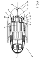
- FIG. 1 an insight into a helicopter cab 0 is shown with main rotor and tail rotor omitted for simplicity.
- S denotes the front tip S of the helicopter cabin 0 and L the longitudinal axis of the helicopter cabin 0.
- L the longitudinal axis of the helicopter cabin 0.
- the configuration in the cockpit area and thus near the tip S of the helicopter cabin 0 is interesting.
- a cabin floor 9 covers a main structure 13 of the helicopter cab 0.
- skid tubes 5 and running boards 14 are arranged on both sides, so that the helicopter cabin 0 can be placed on the skid tubes 5.
- the main structure 13 is at least partially surrounded by an outer skin 17, whereby an at least partially closed helicopter cab 0 is formed.
- the main structure 13 and the outer skin 17 consist essentially of metal or fiber composite struts which form the helicopter cabin 0.
- a pilot's seat 2 is mounted in the direction of the tip S from the interior space on the right side of the helicopter cabin 0.
- the co-pilot seat 3 On the corresponding left side of the helicopter cabin 0 is the co-pilot seat 3 inside the cockpit. If in this application from the right or the right side is mentioned, in each case the side of the pilot seat 3 and thus meant with respect to the tip S from the interior right side meant.
- a Cockpitingabekonsole 8 is arranged, which is operated in the control of the helicopter cabin 0 or the helicopter.
- the collective Blattverstellhebel 6 Directly next to the pilot seat 2 and indeed in the direction of the longitudinal axis L spaced from the pilot seat 2, there is the collective Blattverstellhebel 6, which serves for the collective adjustment of the angle of attack of all rotor blades.
- a pilot's seat 10 as part of the outer skin 17 serves as access to the pilot seat 2 on the right side and correspondingly to a co-pilot's door 12 on the left side as access to the co-pilot seat 3.
- an observation channel 4 is provided, which is arranged between the pilot seat 2 and the co-pilot seat 3.
- FIG. 2 is an inner pane 15 of the observation channel 4 arranged offset left of the pilot seat 2 recognizable.
- This inner pane 15 is accessible from the interior of the helicopter cab 0 and made transparent.
- the opening of the observation channel 4 extends approximately from the instrument cluster 1 to the backrest of the pilot seat 2 and is completely covered with the inner pane 15.
- FIG. 2 shown is the view down through the observation channel 4 unrestricted possible, with no components such as skid tubes 5, running boards 14, Disturb parts of the controller or, for example, wiring below the cabin floor 9.
- a pilot on the pilot's seat 2 has by slight lowering of the head a large viewing angle of the inner pane 15 and the entire observation channel 4 crossing the cabin floor 9.
- the instrument cluster 1 in the cockpit input 8 can by a pilot even during observation of the events almost vertically below of the cabin floor 9 without great effort.
- the interior of the helicopter cabin 0, the observation channel 4 is bounded by the inner pane 15, which is preferably flush with the plane of the cabin floor 9.
- the inner pane 15 is arranged laterally between the pilot seat 2 and the co-pilot seat 3.
- the length of the inner disk 15 corresponds approximately to the depth T of the seat surface and the backrest of the pilot seat 2 in the direction of the longitudinal axis L of the helicopter cabin.
- the clarification of the embodiment of the observation channel 4 is carried out according to a longitudinal section FIG. 4 , which along the section line AA in FIG. 3 is performed.
- the observation channel 4 is located in the main structure 13 of the helicopter cabin 0, the main structure 13 completely crossing. In this case, a corresponding space is recessed in the main structure 13, in which the observation channel 4 is introduced.
- the stability of the inner pane 15 may be formed corresponding to the ground support force of the cabin floor 9, so that it is accessible.
- the inner pane 15 can be covered in passenger transport additionally by a cover, such as a roller shutter 20 or the like.
- a cover such as a roller shutter 20 or the like.
- the ground insert 21 would then be designed to allow 3 seats to be placed in the front row in passenger transports.
- observation channel 4 On the atmospheric side of the observation channel 4 opposite the interior of the helicopter cabin 0, the observation channel 4 is bounded by an outer pane 16, which is preferably flush with the plane of the outer skin 17 of the main structure 13. As a result, the aerodynamic properties of the outer skin 17 remain virtually unchanged.
- the observation channel 4 is thus formed on both sides to the interior of the helicopter canoe 0 and completed to the atmosphere.
- the observation channel 4 is formed by two longitudinal walls 42, wherein in FIG. 5 only one longitudinal wall 42 can be seen. Both longitudinal walls 42 extend at least approximately parallel to the longitudinal axis L and to each other.
- At least a part of at least one of the transverse walls 43, 43 'in an opening angle 7 greater 0 ° between a viewing channel longitudinal axis B and the at least a portion of the respective transverse wall 43, 43' may be arranged.
- the choice of an opening angle 7 of at least about 10 ° between at least one of the transverse walls 43, 43 'and the observation channel longitudinal axis B is advantageous. This is in FIG. 5 shown.
- the cross section of the observation channel 4 is thus increased correspondingly from the interior to the atmosphere side of the helicopter canoe 0.
- the figures shown here show the longitudinal walls 42 and the transverse walls 43, 43 'in each case as part of the main structure 13, which are correspondingly shaped to form the observation channel 4. However, it is also possible to introduce a viewing channel 4 into a recess of the main structure 13. So that the observation channel 4 is removably mounted from the recess in the main structure 13.
- inner pane 15 and outer pane 16 In order to allow optimum visibility, inner pane 15 and outer pane 16 must be made transparent. In order to additionally achieve a certain enlargement effect, the inner pane 15 and / or the outer disk 16 may be concave or convex. Furthermore, mirrors for observing and monitoring the position of the load hook can be introduced directly into the observation channel 4 and fastened there without complex mirror images. By this arrangement of mirrors, the aerodynamic properties of the aircraft are not affected, since they are completely surrounded by the longitudinal walls 42 and transverse walls 43, 43 '.
- the viewing window length 4 can be extended longitudinally in the direction of the cabin as required.
- the observation channel 4 is free of any structural parts 13 and / or control rods. Due to the unrestricted view through the observation channel 4, the underload, or the like, which is connected to the load hook with the length-independent cable load, seen unhindered.
- the pilot who pilots the aircraft on the pilot's seat 2, when using the observation channel 4 occupy an ergonomic position in front of the instrument cluster 1, on which the flight and Motor instruments are placed.
- the observation channel 4 is recessed on the left side of the pilot seat 2, the head rotation is therefore inclined to the left in the center of the helicopter, on the side of the collective Blattverstellhebels 6, which the pilots on the pilot's seat 2 with the controls left hand greatly simplified and additionally increased flight safety.
- a mere eye movement is sufficient to read the underload and / or the instrument data, further providing additional flight safety.
Abstract
Description
Die vorliegende Erfindung beschreibt einen Beobachtungskanal und eine Hubschrauberkabine mit einem Beobachtungskanal.The present invention describes an observation channel and a helicopter cabin with an observation channel.
Die Sicht des Piloten unter ein Drehflügelflugzeug oder einen Drehflügler, insbesondere einen Hubschrauber oder Helikopter, ist in einigen Situationen von sehr grosser Bedeutung.The pilot's view under a rotary wing aircraft or a rotary wing aircraft, especially a helicopter or helicopter, is very important in some situations.
Um Lasten mittels eines Hubschraubers aufnehmen zu können, ist es erwünscht, den Helikopter in eine vertikale Lage über die Last zu manövrieren. Die Position des Lasthakens, welcher mit dem Lastenseil an der Lastenklinke des Helikopters befestigt ist, sollte vertikal möglichst genau über der Stelle der Last gehalten werden, um die Last ohne horizontale Bewegung anheben zu können. Dies ist sehr wichtig, da eine pendelnde Last unterhalb eines Drehflügelflugzeugs sehr gefährlich werden kann und dies aus Gründen der Flugsicherheit unbedingt vermieden werden muss.In order to be able to take up loads by means of a helicopter, it is desirable to maneuver the helicopter in a vertical position over the load. The position of the load hook, which is attached to the load rope on the load pawl of the helicopter, should be vertically held as accurately as possible over the location of the load in order to lift the load without horizontal movement can. This is very important because a swinging load below a rotary wing aircraft can be very dangerous and this must be avoided for safety reasons.
Um die Sicht eines Piloten annähernd vertikal nach unten, unter die Rumpfstruktur eines Helikopters zu gewährleisten werden nach aussen gewölbte Kunstglastüren auf der rechten Pilotenseite, sogenannte "Bubble-Doors" verwendet, wie beispielsweise in
Darin wird eine Glastür beschrieben, welche einfach in einer Seitenwand einer Rumpfstruktur eines Fluggerätes anbringbar ist. Eine Person kann auf einem speziellen Sitz im Bereich der Seitenwand platz nehmen und gemäss einer speziellen Ausführungsform seine Füsse auf einer Fussbodenplatte, im unteren Teil der "bubble door" abstellen. Durch die nach Aussen gewölbte Form der "bubble door" kann ein Beobachter auf dem Sitz sitzend an der Rumpfstruktur des Fluggerätes aussen vorbei teilweise unterhalb die Rumpfstruktur blicken. Der auf dem speziellen Sitz sitzende Passagier greift nicht in die Steuerung des Hubschraubers ein, sondern er beschränkt sich auf die Beobachtung des Raums unterhalb der Rumpfstruktur.In order to ensure the view of a pilot approximately vertically downwards, under the hull structure of a helicopter, curved art glass doors on the right side of the pilot, so-called "bubble doors" are used, such as in
Therein a glass door is described, which is easily attachable in a side wall of a fuselage structure of an aircraft. A person can sit on a special seat in the area of the side wall and, according to a special embodiment, place his feet on a floor plate in the lower part of the "bubble door". Due to the convex shape of the "bubble door", an observer sitting on the seat can look past the fuselage structure of the aircraft outside partially below the fuselage structure. The passenger sitting on the special seat does not interfere with the helicopter's control, but limits himself to observing the space below the fuselage structure.
Würde eine "bubble door" in der Tür auf der rechten Pilotenseite angeordnet, wäre es dem, in einem Hubschrauber auf der rechten Seite sitzenden Piloten möglich unter das Drehflügelflugzeug zu blicken.If a "bubble door" were arranged in the door on the right-hand side of the pilot, it would be possible for the pilot sitting in a helicopter on the right-hand side to look under the rotary-wing aircraft.
Neben den "bubble doors" sind in der Kabinenbodenfläche der Rumpfstruktur anbringbare sogenannte "Vertical reference floor windows" bekannt, welche in diversen Grössen für einige Hubschraubermodelle erhältlich sind. Diese Fenster werden in der Kabinenbodenfläche zwischen Pilotensitz und Tür im Bereich der rechten Pilotenseite angebracht. Damit kann der Pilot den vertikalen Abstand des Hubschraubers einschätzen, wobei er an seiner rechten Körperhälfte vorbei durch das Fenster schauen muss.In addition to the "bubble doors", so-called "vertical reference floor windows" are available in the cabin floor space of the fuselage structure, which are available in various sizes for some helicopter models. These windows are located in the cabin floor area between Pilots seat and door mounted in the area of the right pilot side. This allows the pilot to estimate the vertical distance of the helicopter, having to look past his right half of the body through the window.
Mit den heutigen Hilfsmitteln wie Bubble-Door, und "Vertical reference floor windows", ist es dem Piloten möglich, die Unterlast zu sehen. Jedoch sind grosse Oberkörperbewegungen auf dem Pilotensitz erforderlich um den Kopf in die gewölbte Tür oder über das "Vertical reference floor window" zu bewegen. Vor allem bei kurzen Seillängen muss sich der Pilot noch stärker nach rechts beugen, um die Unterlast zu sehen. Die stark nach rechts gebeugte Position des Piloten, welche vom links liegenden kollektiven Blattverstellhebel weggebeugt ist, bedingt eine Verlängerung des kollektiven Blattverstellhebels.With today's tools such as Bubble-Door, and "Vertical reference floor windows", it is possible for the pilot to see the underload. However, large torso movements on the pilot's seat are required to move the head into the arched door or over the vertical reference floor window. Especially with short pitches, the pilot has to bend even more to the right to see the underload. The heavily bent to the right position of the pilot, which is bent away from the left collective Blattverstellhebel, due to an extension of the collective Blattverstellhebels.
Da der Kopf des Piloten bei Unterlastaufgaben weit nach rechts aus dem Fenster geneigt ist, können die Instrumente welche im Instrumentenpilz mittig eingebaut sind, schlecht, oder nur mit grossen Kopf- und Oberkörperbewegungen überprüft werden.Since the pilot's head is tilted far to the right out of the window during underloading tasks, the instruments which are installed centrally in the instrument cluster can be checked poorly, or only with large head and torso movements.
Sollten beispielsweise elektronische und/oder mechanische Ausfällen der Motorsteuerung auftreten ist der Pilot gezwungen, die Motorparameter über den Gasdrehgriff, welcher auf dem kollektiven Blattverstellhebel sitzt, von Hand zu regeln. Wird nun mit den oben beschriebenen Sicht-Möglichkeiten Unterlast geflogen, umfasst die linke Hand nicht den Gasdrehgriff, was bei einem technischen Motorkontrollproblem einen ganzen Körpereinsatz und natürlich einem Handwechsel, von der kollektiven Blattverstellungsverlängerung zum Gasdrehgriff zur Folge hat.If, for example, electronic and / or mechanical failures of the engine control occur, the pilot is forced to manually control the engine parameters via the throttle twistgrip, which sits on the collective pitch control lever. Now with the view options described above Underload, the left hand does not include the throttle grip, resulting in a technical engine control problem, a whole body use and, of course, a hand change, from the collective blade pitch extension to the throttle grip.
Während bereits im fehlerfreien Zustand der Motorsteuerung hohe Anforderungen an den Piloten gestellt werden, ist die Flugsicherheit bei oben beschriebenen Ausfällen stark reduziert.While high demands are placed on the pilot in error-free condition of the engine control, the flight safety is greatly reduced in the above-described failures.
Um die Sicht nach unten zu verbessern hat man sich bislang mit der Anbringung von Spiegeln behelfen müssen, oder aber der Pilot hat sich auf den linken Sitz positioniert, was nicht bei allen Hubschraubermodellen möglich ist und teilweise nur durch einen umfangreichen Umbau und eine Zusatzzertifizierung erreichbar ist. Da die Sicht unter das Luftfahrzeug durch den Kabinenboden, die Kufen, montierte Trittbretter und auch Skis oftmals stark behindert ist, hat die Sichtverbesserung mittels dieser Hilfsmittel auch ihre Grenzen, wobei der Pilot weiterhin deutlich von einer entspannten Sitz- und Steuerposition abweicht.In order to improve the view downwards, it has been necessary to help with the installation of mirrors, or the pilot has positioned himself on the left seat, which is not possible with all models of helicopters and can only be achieved through extensive modification and additional certification , Since the view under the aircraft through the cabin floor, the skids, mounted running boards and skis is often severely hampered, the visual improvement by means of these tools also has its limits, the pilot still deviates significantly from a relaxed sitting and steering position.
Die vorliegende Erfindung hat sich zur Aufgabe gestellt ein Drehflügelflugzeug bereit zu stellen, in welchem die Sicht auf eine Unterlast derart erreicht wird, dass der Sitz- und Steuerkomfort für den Piloten verbessert ist. Eine weitere Aufgabe besteht in der Erreichung einer verbesserten Flugsicherheit, da der Pilot entspannter und ermüdungsärmer Flugmanöver mit Unterlast fliegen kann.The present invention has for its object to provide a rotary wing aircraft in which the view of an underload is achieved such that the seating and control comfort for the pilot is improved. Another task is to achieve improved flight safety, as the pilot can fly relaxed and fatigue-poor maneuvers with underload.
Durch die Ausgestaltung eines Drehflügelflugzeuges mit einem im Kabinenboden angeordneten Beobachtungskanal, welcher zwischen Pilotensitz und Copilotensitz angeordnet ist in Richtung Front des Drehflügelflugzeugs wird diese Aufgabe gelöst, wobei der Pilot ohne grosse Kopfdrehung eine freie Sicht unter das Luftfahrzeug erhält.Due to the configuration of a rotary-wing aircraft with an observation channel arranged in the cabin floor, which is arranged between pilot seat and copilot seat in the direction of the rotary-wing aircraft, this object is achieved, wherein the pilot receives a clear view under the aircraft without large head rotation.
Die durch die Erfindung erreichten Vorteile sind im wesentlichen darin zu sehen, dass dem Piloten neben einer direkten, ungehinderten und damit wirklichkeitsgetreuen Ansicht des Raumes unterhalb des Helikopters, zu jeder Zeit eine ergonomische Sitzposition erlaubt ist, welche es dem Piloten ermöglicht, die Blickrichtung ohne Oberkörperbewegung einfach zwischen dem Raum unterhalb des Luftfahrzeuges und den Instrumentenparameter zu wechseln.The advantages achieved by the invention are essentially to be seen in the fact that the pilot in addition to a direct, unobstructed and thus realistic view of the space below the helicopter, at any time an ergonomic seating position is allowed, which allows the pilot, the viewing direction without upper body movement simply switch between the space below the aircraft and the instrument parameters.
Die Position des Piloten ist in den Innenraum des Helikopters geneigt, was wiederum die Steuerorgan-Erreichbarkeit begünstigt und damit die Flugsicherheit erhöht.The position of the pilot is inclined in the interior of the helicopter, which in turn favors the control organ accessibility and thus increases flight safety.
Durch die Ausgestaltung des Beobachtungskanals wird eine Sichtmöglichkeit unter den Helikopter geschaffen, wobei die Hauptstruktur und insbesondere der Kabinenboden in seiner Stabilität nicht geschwächt wird. Die Konstruktion des Beobachtungskanals hat eher einen stabilisierenden Einfluss auf die Hauptstruktur.The design of the observation channel creates a view under the helicopter, wherein the main structure and in particular the cabin floor is not weakened in its stability. The construction of the observation channel has more of a stabilizing influence on the main structure.
Ein bevorzugtes Ausführungsbeispiel des Erfindungsgegenstandes wird nachstehend im Zusammenhang mit den anliegenden Zeichnungen beschrieben.
Figur 1- zeigt eine Aufsicht auf eine Hubschrauberkabine, wobei der Hauptrotor und der Heckrotor weggelassen wurden, während
Figur 2- eine perspektivische Teilansicht eines Innenraumes einer Hubschrauberkabine ohne Hauptrotor gemäss
Figur 1 Figur 3- zeigt einen Teil einer Aufsicht auf einen Hubschrauber mit einer geringfügig von der Längsachse abweichenden Schnittlinie A-A, während
Figur 4- einen Längsschnitt gemäss Schnittlinie A-A aus
Figur 3 Figur 5- zeigt einen detaillierten Längsschnitt gemäss rechteckiger Kennzeichnung in
Figur 4
- FIG. 1
- shows a plan view of a helicopter cabin, with the main rotor and the tail rotor have been omitted while
- FIG. 2
- a partial perspective view of an interior of a helicopter cabin without main rotor according
FIG. 1 shows. - FIG. 3
- shows a part of a plan view of a helicopter with a slightly deviating from the longitudinal axis section line AA, while
- FIG. 4
- a longitudinal section along section line AA
FIG. 3 shows. - FIG. 5
- shows a detailed longitudinal section according to rectangular marking in
FIG. 4 ,
In
Ein Kabinenboden 9 überdeckt eine Hauptstruktur 13 der Hubschrauberkabine 0. An der tragenden Hauptstruktur 13 sind Kufenrohre 5 und Trittbretter 14 beidseitig angeordnet, sodass die Hubschrauberkabine 0 auf den Kufenrohren 5 abstellbar ist. Die Hauptstruktur 13 ist zumindest teilweise mit einer Aussenhaut 17 umgeben, wodurch eine mindestens teilweise geschlossene Hubschrauberkabine 0 gebildet wird. Neben Kunstglas besteht die Hauptstruktur 13 und die Aussenhaut 17 im Wesentlichen aus Metall- oder Faserverbundwerkstoff-Streben welche die Hubschrauberkabine 0 bilden.A
Ein Pilotensitz 2 ist bei Blick in Richtung Spitze S aus dem Innenraum auf der rechten Seite der Hubschrauberkabine 0 angebracht. Auf der entsprechenden linken Seite der Hubschrauberkabine 0 befindet sich der Co-Pilotensitz 3 innerhalb des Cockpits. Wenn in dieser Anmeldung von rechts oder der rechten Seite die Rede ist, ist jeweils die Seite des Pilotensitzes 3 und damit die mit Blick auf die Spitze S aus dem Innenraum definierte rechte Seite gemeint. Zwischen dem Pilotensitz 2 und dem Co-Pilotensitz 3 ist eine Cockpiteingabekonsole 8 angeordnet, welche bei der Steuerung der Hubschrauberkabine 0 bzw. des Hubschraubers bedient wird. Direkt neben dem Pilotensitz 2 und zwar in Richtung Längsachse L vom Pilotensitz 2 beabstandet, befindet sich der kollektive Blattverstellhebel 6, welcher zur kollektiven Verstellung des Anstellwinkels aller Rotorblätter dient.A pilot's
Eine Pilotensitztür 10 als Teil der Aussenhaut 17 dient als Zugang zum Pilotensitz 2 auf der rechten Seite und entsprechend eine Co-Pilotensitztür 12 auf der linken Seite als Zugang zum Co-Pilotensitz 3.A pilot's
Um die Sicht unter den Kabinenboden 9 zu erreichen, ist ein Beobachtungskanal 4 vorgesehen, welcher zwischen dem Pilotensitz 2 und dem Co-Pilotensitz 3 angeordnet ist.In order to achieve the view under the
In
Wie in
Zum Innenraum der Hubschrauberkabine 0 wird der Beobachtungskanal 4 von der Innenscheibe 15 begrenzt, welche bevorzugt bündig mit der Ebene des Kabinenbodens 9 ist. Die Innenscheibe 15 ist lateral zwischen dem Pilotensitz 2 und dem Co-Pilotensitz 3 angeordnet. Die Länge der Innenscheibe 15 entspricht in Richtung der Längsachse L der Hubschrauberkabine 0 etwa der Tiefe T der Sitzfläche und der Rückenlehne des Pilotensitzes 2.The interior of the
Die Verdeutlichung der Ausgestaltung des Beobachtungskanals 4 erfolgt an einem Längsschnitt gemäss
Der Beobachtungskanal 4 befindet sich in der Hauptstruktur 13 der Hubschrauberkabine 0, die Hauptstruktur 13 vollständig querend. Dabei ist ein entsprechender Raum in der Hauptstruktur 13 ausgespart, in welchen der Beobachtungskanal 4 eingebracht ist.The
Die Stabilität der Innenscheibe 15 kann der Bodentragkraft des Kabinenbodens 9 entsprechend ausgebildet sein, damit diese begehbar ist. Die Innenscheibe 15 kann bei Personentransporten zusätzlich durch eine Abdeckung, beispielsweise einen Rollladen 20 oder dergleichen abgedeckt werden. Es ist aber auch vorstellbar die Innenscheibe 15 lösbar befestigt auf der Öffnung des Beobachtungskanals 4 zu lagern, sodass die Innenscheibe 15 durch einen entsprechend geformten Bodeneinsatz 21 ausgetauscht werden kann. Der Bodeneinsatz 21 wäre dann derart ausgeführt, dass er bei Personentransporten ermöglicht, dass 3 Sitze in der vorderen Reihe platziert werden können.The stability of the
Auf der dem Innenraum der Hubschrauberkabine 0 entgegengesetzten Atmosphärenseite des Beobachtungskanals 4 wird der Beobachtungskanal 4 durch eine Aussenscheibe 16 begrenzt, welche bevorzugt bündig zur Ebene der Aussenhaut 17 der Hauptstruktur 13 ist. Dadurch bleiben die aerodynamischen Eigenschaften der Aussenhaut 17 nahezu unverändert. Der Beobachtungskanal 4 ist damit beidseitig zum Innenraum der Hubschrauberkanine 0 und zur Atmosphäre abgeschlossen ausgebildet.On the atmospheric side of the
Der Beobachtungskanal 4 wird durch zwei Längswände 42 gebildet, wobei in
Eine vordere Querwand 43 und eine hintere Querwand 43' mindestens annähernd senkrecht zur Längsachse L verlaufend, grenzen den Beobachtungskanal 4 nach vorne und hinten in Richtung der Längsachse L gegen die Hauptstruktur 13 ab.A front
Um die Sichtreferenz auch bei unterschiedlichen Lastenseillängen zu vergrössern, kann mindestens ein Teil mindestens einer der Querwände 43, 43' in einem Öffnungswinkel 7 grösser 0° zwischen einer Beobachtungskanallängsachse B und dem mindestens einen Teil der jeweiligen Querwand 43, 43' angeordnet sein. Insbesondere ist die Wahl eines Öffnungswinkels 7 von mindestens etwa 10° zwischen mindestens einer der Querwände 43, 43' und der Beobachtungskanallängsachse B vorteilhaft. Dies ist in
Die hier dargestellten Figuren zeigen die Längswände 42 und die Querwände 43, 43' jeweils als Teil der Hauptstruktur 13, welche zur Ausbildung des Beobachtungskanals 4 entsprechend geformt sind. Es ist aber auch möglich in eine Aussparung der Hauptstruktur 13 einen Beobachtungskanal 4 einzubringen. Sodass der Beobachtungskanal 4 aus der Aussparung in der Hauptstruktur 13 entfernbar gelagert ist.The figures shown here show the
Um eine optimale Sicht zu ermöglichen müssen Innenscheibe 15 und Aussenscheibe 16 transparent ausgeführt sein. Um zusätzlich einen gewissen Vergrösserungseffekt zu erzielen, kann die Innenscheibe 15 und/oder die Aussenscheibe 16 konkav oder konvex ausgeführt sein.
Im Weiteren können Spiegel zur Beobachtung und Überwachung der Stellung des Lasthakens ohne aufwändige Spiegelaufnahmen direkt in den Beobachtungskanal 4 eingebracht und dort befestigt werden. Durch diese Anordnung von Spiegeln werden die aerodynamischen Eigenschaften des Luftfahrtzeuges nicht beeinträchtigt, da diese von den Längswänden 42 und Querwänden 43, 43' vollständig umgeben sind.In order to allow optimum visibility,
Furthermore, mirrors for observing and monitoring the position of the load hook can be introduced directly into the
Die Sichtfensterlänge 4 ist je nach Bedarf longitudinal in Richtung der Kabine verlängerbar.The
Durch den Beobachtungskanal 4 wird eine vertikale Sichtreferenz unterhalb das Luftfahrtzeug erhalten. Sichteinbussen auf die Unterlast, welche bei Verwendung von "Bubble-Door"-Vorrichtungen durch Kufenrohre 5, wie auch Trittbretter 14 öfters Vorkommen, sind ausgeschlossen.Through the
Der Beobachtungskanal 4 ist frei von jeglichen Strukturteilen 13 und/oder Steuergestängen. Durch die uneingeschränkte Sicht durch den Beobachtungskanal 4, wird die Unterlast, oder Dergleichen, welche am Lasthaken mit dem längenunabhängigen Lastenseil verbunden ist, ungehindert gesehen.The
Der Pilot, welcher auf dem Pilotensitz 2 das Luftfahrzeug pilotiert, kann beim Gebrauch des Beobachtungskanals 4 eine ergonomische Position vor dem Instrumentenpilz 1 einnehmen, auf welchem die Flug- und Motorinstrumente platziert sind. Dadurch, dass der Beobachtungskanal 4 auf der linken Seite des Pilotensitzes 2 eingelassen ist, ist bei Unterlasteinsätzen die Kopfdrehung demnach nach links in die Mitte des Helikopters geneigt, auf die Seite des kollektiven Blattverstellhebels 6, was dem Piloten auf dem Pilotensitz 2 das Steuern mit der linken Hand stark vereinfacht und zusätzlich die Flugsicherheit erhöht. Dadurch, dass der Kopf bei Unterlastmissionen genau vor den Fluginstrumenten platziert ist, genügt eine reine Augenbewegung um die Unterlast und/oder die Instrumentendaten abzulesen, was weiter für zusätzliche Flugsicherheit sorgt.The pilot, who pilots the aircraft on the pilot's
- 00
- Hubschrauberkabinehelicopter cabin
- 11
- Instrumentenpilzinstrument panel
- 22
- Pilotensitzpilot's seat
- 33
- Co-PilotensitzCo-pilot's seat
- 44
- Beobachtungskanalobservation channel
- 1515
- Innenscheibeinner pane
- 1616
- Aussenscheibeouter pane
- 4242
- Längswandlongitudinal wall
- 43, 43'43, 43 '
- Querwand (vordere/hintere)Transverse wall (front / rear)
- 55
- KufenrohrKufenrohr
- 66
- Kollektiver BlattverstellhebelCollective blade adjustment lever
- 77
- Öffnungswinkelopening angle
- 88th
- CockpiteingabekonsoleCockpit input console
- 99
- Kabinenbodencabin floor
- 1010
- PilotensitztürPilot seat door
- 1212
- Co-PilotensitztürCo-pilot's seat door
- 1313
- Hauptstrukturmain structure
- 1414
- Trittbrettrunning board
- 1717
- Aussenhautouter skin
- 2020
- Rolladenshutters
- 2121
- Bodeneinsatzfloor insert
- SS
- Spitzetop
- LL
- Längsachselongitudinal axis
- TT
- Tiefedepth
Claims (11)
wobei die Öffnung des Beobachtungskanals (4) zum Innenraum mit einer Innenscheibe (15) und die Öffnung des Beobachtungskanals (4) zur Atmosphäre mit einer Aussenscheibe (16) lösbar oder unlösbar verbunden bedeckt ist.Observation channel (4) in a main structure (13) of a helicopter cabin (0), which between a pilot seat (2) and a co-pilot seat (3), the main structure (13) from a cabin floor (9) to an outer skin (17) of Helicopter cab (0) can be arranged completely across,
wherein the opening of the observation channel (4) is covered to the interior with an inner pane (15) and the opening of the observation channel (4) to atmosphere with an outer pane (16) releasably or non-detachably connected.
Applications Claiming Priority (1)
| Application Number | Priority Date | Filing Date | Title |
|---|---|---|---|
| CH00346/11A CH704540A2 (en) | 2011-02-28 | 2011-02-28 | Observation channel and helicopter cabin with an observation channel. |
Publications (3)
| Publication Number | Publication Date |
|---|---|
| EP2492189A2 true EP2492189A2 (en) | 2012-08-29 |
| EP2492189A3 EP2492189A3 (en) | 2014-12-24 |
| EP2492189B1 EP2492189B1 (en) | 2016-05-11 |
Family
ID=45656584
Family Applications (1)
| Application Number | Title | Priority Date | Filing Date |
|---|---|---|---|
| EP12156783.8A Active EP2492189B1 (en) | 2011-02-28 | 2012-02-24 | Observation channel and helicopter cabin |
Country Status (3)
| Country | Link |
|---|---|
| US (1) | US8783613B2 (en) |
| EP (1) | EP2492189B1 (en) |
| CH (1) | CH704540A2 (en) |
Cited By (1)
| Publication number | Priority date | Publication date | Assignee | Title |
|---|---|---|---|---|
| CH710657A1 (en) * | 2015-01-28 | 2016-07-29 | Marenco Swisshelicopter Ag | Helicopter cabin. |
Families Citing this family (2)
| Publication number | Priority date | Publication date | Assignee | Title |
|---|---|---|---|---|
| FR3003841B1 (en) | 2013-03-26 | 2015-07-17 | Eurocopter France | AIRCRAFT WITH OPTIMIZED EXTERNAL VISIBILITY COCKPIT AND METHOD. |
| CN112078810A (en) * | 2020-08-20 | 2020-12-15 | 中国南方电网有限责任公司超高压输电公司检修试验中心 | Platform of photoelectric observation system in cabin and installation method thereof |
Citations (2)
| Publication number | Priority date | Publication date | Assignee | Title |
|---|---|---|---|---|
| FR2894561A1 (en) | 2005-12-14 | 2007-06-15 | Eurocopter France | AEROTRANSPORTABLE RESERVOIR FOR STORING A PRODUCT TO LARGUER IN FLIGHT |
| WO2009051711A1 (en) | 2007-10-15 | 2009-04-23 | Woodland Richard L K | A temporarily installed aircraft observer door plug, chair, sonotube ejection and control system |
Family Cites Families (3)
| Publication number | Priority date | Publication date | Assignee | Title |
|---|---|---|---|---|
| US2942811A (en) * | 1958-01-21 | 1960-06-28 | Bell Robert | Airplane with sightseeing lounge floor |
| US3572615A (en) * | 1969-03-07 | 1971-03-30 | Floyd A Firestone | Airplane with spatial panorama |
| DE3629838A1 (en) * | 1986-07-09 | 1988-01-28 | Heinz Martin Hadeball | Aircraft |
-
2011
- 2011-02-28 CH CH00346/11A patent/CH704540A2/en not_active Application Discontinuation
-
2012
- 2012-02-24 EP EP12156783.8A patent/EP2492189B1/en active Active
- 2012-02-27 US US13/405,838 patent/US8783613B2/en active Active
Patent Citations (2)
| Publication number | Priority date | Publication date | Assignee | Title |
|---|---|---|---|---|
| FR2894561A1 (en) | 2005-12-14 | 2007-06-15 | Eurocopter France | AEROTRANSPORTABLE RESERVOIR FOR STORING A PRODUCT TO LARGUER IN FLIGHT |
| WO2009051711A1 (en) | 2007-10-15 | 2009-04-23 | Woodland Richard L K | A temporarily installed aircraft observer door plug, chair, sonotube ejection and control system |
Cited By (2)
| Publication number | Priority date | Publication date | Assignee | Title |
|---|---|---|---|---|
| CH710657A1 (en) * | 2015-01-28 | 2016-07-29 | Marenco Swisshelicopter Ag | Helicopter cabin. |
| EP3050795A1 (en) | 2015-01-28 | 2016-08-03 | Marenco Swisshelicopter AG | Helicopter cabin |
Also Published As
| Publication number | Publication date |
|---|---|
| US20120217345A1 (en) | 2012-08-30 |
| CH704540A2 (en) | 2012-08-31 |
| EP2492189A3 (en) | 2014-12-24 |
| US8783613B2 (en) | 2014-07-22 |
| EP2492189B1 (en) | 2016-05-11 |
Similar Documents
| Publication | Publication Date | Title |
|---|---|---|
| EP3050795B1 (en) | Helicopter cabin | |
| DE60206737T2 (en) | Overhead luggage rack in aircraft | |
| DE102006032003A1 (en) | Trimmable tailplane | |
| EP2492189B1 (en) | Observation channel and helicopter cabin | |
| DE4405975A1 (en) | VTOL swept wing, e.g. canard aircraft | |
| DE60302643T2 (en) | Method and device for controlling aircraft rudders | |
| DE102005048709A1 (en) | Vertically movable corridor for rest rooms in the ceiling area | |
| DE112020005430T5 (en) | ROAD-READY AIRCRAFT | |
| DE202016106543U1 (en) | Dome module with position sensor | |
| EP3708483A1 (en) | Clamping and holding device for wall modules | |
| EP3681797B1 (en) | Autogyro having an instrument panel | |
| EP1820729B1 (en) | Aeroplane seat fastening device | |
| DE102014100027B4 (en) | Helicopter with a H-shaped construction | |
| DE202017106907U1 (en) | Horizon Reference Display to show a horizontal orientation of a vessel | |
| CH664333A5 (en) | Window for helicopter - has extended shape to give pilot view directly under aircraft | |
| DE699158C (en) | Airplane wing with an engine that can be pivoted about the transverse axis | |
| DE434968C (en) | Stabilization device for aircraft by means of pendulum suspended payloads | |
| DE3629838A1 (en) | Aircraft | |
| DE730493C (en) | Twin-engine aircraft with tension and compression screw | |
| WO2016166256A1 (en) | Aircraft | |
| DE379871C (en) | plane | |
| DE473867C (en) | Device for increasing the landing glide angle on aircraft | |
| DE711216C (en) | Airplane with jointly swiveling wing and horizontal stabilizer | |
| DE1199627B (en) | Ground training device for the training of helicopter pilots | |
| DE102011122594A1 (en) | Jet aircraft with at least one jet engine and with pivoting wings |
Legal Events
| Date | Code | Title | Description |
|---|---|---|---|
| PUAI | Public reference made under article 153(3) epc to a published international application that has entered the european phase |
Free format text: ORIGINAL CODE: 0009012 |
|
| AK | Designated contracting states |
Kind code of ref document: A2 Designated state(s): AL AT BE BG CH CY CZ DE DK EE ES FI FR GB GR HR HU IE IS IT LI LT LU LV MC MK MT NL NO PL PT RO RS SE SI SK SM TR |
|
| AX | Request for extension of the european patent |
Extension state: BA ME |
|
| TPAC | Observations filed by third parties |
Free format text: ORIGINAL CODE: EPIDOSNTIPA |
|
| RAP1 | Party data changed (applicant data changed or rights of an application transferred) |
Owner name: MARENCO SWISSHELICOPTER DESIGN AG |
|
| PUAL | Search report despatched |
Free format text: ORIGINAL CODE: 0009013 |
|
| AK | Designated contracting states |
Kind code of ref document: A3 Designated state(s): AL AT BE BG CH CY CZ DE DK EE ES FI FR GB GR HR HU IE IS IT LI LT LU LV MC MK MT NL NO PL PT RO RS SE SI SK SM TR |
|
| AX | Request for extension of the european patent |
Extension state: BA ME |
|
| RIC1 | Information provided on ipc code assigned before grant |
Ipc: B64C 27/04 20060101ALI20141118BHEP Ipc: B64D 7/00 20060101ALI20141118BHEP Ipc: B64C 1/14 20060101AFI20141118BHEP |
|
| RAP1 | Party data changed (applicant data changed or rights of an application transferred) |
Owner name: MARENCO SWISSHELICOPTER AG |
|
| 17P | Request for examination filed |
Effective date: 20150601 |
|
| RBV | Designated contracting states (corrected) |
Designated state(s): AL AT BE BG CH CY CZ DE DK EE ES FI FR GB GR HR HU IE IS IT LI LT LU LV MC MK MT NL NO PL PT RO RS SE SI SK SM TR |
|
| GRAP | Despatch of communication of intention to grant a patent |
Free format text: ORIGINAL CODE: EPIDOSNIGR1 |
|
| INTG | Intention to grant announced |
Effective date: 20151215 |
|
| GRAS | Grant fee paid |
Free format text: ORIGINAL CODE: EPIDOSNIGR3 |
|
| GRAA | (expected) grant |
Free format text: ORIGINAL CODE: 0009210 |
|
| AK | Designated contracting states |
Kind code of ref document: B1 Designated state(s): AL AT BE BG CH CY CZ DE DK EE ES FI FR GB GR HR HU IE IS IT LI LT LU LV MC MK MT NL NO PL PT RO RS SE SI SK SM TR |
|
| REG | Reference to a national code |
Ref country code: GB Ref legal event code: FG4D Free format text: NOT ENGLISH |
|
| REG | Reference to a national code |
Ref country code: CH Ref legal event code: EP |
|
| REG | Reference to a national code |
Ref country code: AT Ref legal event code: REF Ref document number: 798429 Country of ref document: AT Kind code of ref document: T Effective date: 20160515 |
|
| REG | Reference to a national code |
Ref country code: IE Ref legal event code: FG4D Free format text: LANGUAGE OF EP DOCUMENT: GERMAN |
|
| REG | Reference to a national code |
Ref country code: DE Ref legal event code: R096 Ref document number: 502012007042 Country of ref document: DE |
|
| REG | Reference to a national code |
Ref country code: CH Ref legal event code: NV Representative=s name: SCHNEIDER FELDMANN AG PATENT- UND MARKENANWAEL, CH |
|
| REG | Reference to a national code |
Ref country code: LT Ref legal event code: MG4D |
|
| REG | Reference to a national code |
Ref country code: NL Ref legal event code: MP Effective date: 20160511 |
|
| PG25 | Lapsed in a contracting state [announced via postgrant information from national office to epo] |
Ref country code: FI Free format text: LAPSE BECAUSE OF FAILURE TO SUBMIT A TRANSLATION OF THE DESCRIPTION OR TO PAY THE FEE WITHIN THE PRESCRIBED TIME-LIMIT Effective date: 20160511 Ref country code: NL Free format text: LAPSE BECAUSE OF FAILURE TO SUBMIT A TRANSLATION OF THE DESCRIPTION OR TO PAY THE FEE WITHIN THE PRESCRIBED TIME-LIMIT Effective date: 20160511 Ref country code: NO Free format text: LAPSE BECAUSE OF FAILURE TO SUBMIT A TRANSLATION OF THE DESCRIPTION OR TO PAY THE FEE WITHIN THE PRESCRIBED TIME-LIMIT Effective date: 20160811 Ref country code: LT Free format text: LAPSE BECAUSE OF FAILURE TO SUBMIT A TRANSLATION OF THE DESCRIPTION OR TO PAY THE FEE WITHIN THE PRESCRIBED TIME-LIMIT Effective date: 20160511 |
|
| PG25 | Lapsed in a contracting state [announced via postgrant information from national office to epo] |
Ref country code: HR Free format text: LAPSE BECAUSE OF FAILURE TO SUBMIT A TRANSLATION OF THE DESCRIPTION OR TO PAY THE FEE WITHIN THE PRESCRIBED TIME-LIMIT Effective date: 20160511 Ref country code: SE Free format text: LAPSE BECAUSE OF FAILURE TO SUBMIT A TRANSLATION OF THE DESCRIPTION OR TO PAY THE FEE WITHIN THE PRESCRIBED TIME-LIMIT Effective date: 20160511 Ref country code: GR Free format text: LAPSE BECAUSE OF FAILURE TO SUBMIT A TRANSLATION OF THE DESCRIPTION OR TO PAY THE FEE WITHIN THE PRESCRIBED TIME-LIMIT Effective date: 20160812 Ref country code: RS Free format text: LAPSE BECAUSE OF FAILURE TO SUBMIT A TRANSLATION OF THE DESCRIPTION OR TO PAY THE FEE WITHIN THE PRESCRIBED TIME-LIMIT Effective date: 20160511 Ref country code: ES Free format text: LAPSE BECAUSE OF FAILURE TO SUBMIT A TRANSLATION OF THE DESCRIPTION OR TO PAY THE FEE WITHIN THE PRESCRIBED TIME-LIMIT Effective date: 20160511 Ref country code: LV Free format text: LAPSE BECAUSE OF FAILURE TO SUBMIT A TRANSLATION OF THE DESCRIPTION OR TO PAY THE FEE WITHIN THE PRESCRIBED TIME-LIMIT Effective date: 20160511 Ref country code: PT Free format text: LAPSE BECAUSE OF FAILURE TO SUBMIT A TRANSLATION OF THE DESCRIPTION OR TO PAY THE FEE WITHIN THE PRESCRIBED TIME-LIMIT Effective date: 20160912 |
|
| PG25 | Lapsed in a contracting state [announced via postgrant information from national office to epo] |
Ref country code: RO Free format text: LAPSE BECAUSE OF FAILURE TO SUBMIT A TRANSLATION OF THE DESCRIPTION OR TO PAY THE FEE WITHIN THE PRESCRIBED TIME-LIMIT Effective date: 20160511 Ref country code: DK Free format text: LAPSE BECAUSE OF FAILURE TO SUBMIT A TRANSLATION OF THE DESCRIPTION OR TO PAY THE FEE WITHIN THE PRESCRIBED TIME-LIMIT Effective date: 20160511 Ref country code: SK Free format text: LAPSE BECAUSE OF FAILURE TO SUBMIT A TRANSLATION OF THE DESCRIPTION OR TO PAY THE FEE WITHIN THE PRESCRIBED TIME-LIMIT Effective date: 20160511 Ref country code: CZ Free format text: LAPSE BECAUSE OF FAILURE TO SUBMIT A TRANSLATION OF THE DESCRIPTION OR TO PAY THE FEE WITHIN THE PRESCRIBED TIME-LIMIT Effective date: 20160511 Ref country code: EE Free format text: LAPSE BECAUSE OF FAILURE TO SUBMIT A TRANSLATION OF THE DESCRIPTION OR TO PAY THE FEE WITHIN THE PRESCRIBED TIME-LIMIT Effective date: 20160511 |
|
| REG | Reference to a national code |
Ref country code: FR Ref legal event code: PLFP Year of fee payment: 6 |
|
| REG | Reference to a national code |
Ref country code: DE Ref legal event code: R097 Ref document number: 502012007042 Country of ref document: DE |
|
| PG25 | Lapsed in a contracting state [announced via postgrant information from national office to epo] |
Ref country code: PL Free format text: LAPSE BECAUSE OF FAILURE TO SUBMIT A TRANSLATION OF THE DESCRIPTION OR TO PAY THE FEE WITHIN THE PRESCRIBED TIME-LIMIT Effective date: 20160511 Ref country code: SM Free format text: LAPSE BECAUSE OF FAILURE TO SUBMIT A TRANSLATION OF THE DESCRIPTION OR TO PAY THE FEE WITHIN THE PRESCRIBED TIME-LIMIT Effective date: 20160511 |
|
| PLBE | No opposition filed within time limit |
Free format text: ORIGINAL CODE: 0009261 |
|
| STAA | Information on the status of an ep patent application or granted ep patent |
Free format text: STATUS: NO OPPOSITION FILED WITHIN TIME LIMIT |
|
| 26N | No opposition filed |
Effective date: 20170214 |
|
| PG25 | Lapsed in a contracting state [announced via postgrant information from national office to epo] |
Ref country code: BE Free format text: LAPSE BECAUSE OF NON-PAYMENT OF DUE FEES Effective date: 20170228 Ref country code: SI Free format text: LAPSE BECAUSE OF FAILURE TO SUBMIT A TRANSLATION OF THE DESCRIPTION OR TO PAY THE FEE WITHIN THE PRESCRIBED TIME-LIMIT Effective date: 20160511 |
|
| PG25 | Lapsed in a contracting state [announced via postgrant information from national office to epo] |
Ref country code: MC Free format text: LAPSE BECAUSE OF FAILURE TO SUBMIT A TRANSLATION OF THE DESCRIPTION OR TO PAY THE FEE WITHIN THE PRESCRIBED TIME-LIMIT Effective date: 20160511 |
|
| REG | Reference to a national code |
Ref country code: IE Ref legal event code: MM4A |
|
| PG25 | Lapsed in a contracting state [announced via postgrant information from national office to epo] |
Ref country code: LU Free format text: LAPSE BECAUSE OF NON-PAYMENT OF DUE FEES Effective date: 20170224 |
|
| REG | Reference to a national code |
Ref country code: BE Ref legal event code: MM Effective date: 20170228 |
|
| REG | Reference to a national code |
Ref country code: FR Ref legal event code: PLFP Year of fee payment: 7 |
|
| PG25 | Lapsed in a contracting state [announced via postgrant information from national office to epo] |
Ref country code: IE Free format text: LAPSE BECAUSE OF NON-PAYMENT OF DUE FEES Effective date: 20170224 |
|
| REG | Reference to a national code |
Ref country code: AT Ref legal event code: MM01 Ref document number: 798429 Country of ref document: AT Kind code of ref document: T Effective date: 20170224 |
|
| PG25 | Lapsed in a contracting state [announced via postgrant information from national office to epo] |
Ref country code: AT Free format text: LAPSE BECAUSE OF NON-PAYMENT OF DUE FEES Effective date: 20170224 |
|
| PG25 | Lapsed in a contracting state [announced via postgrant information from national office to epo] |
Ref country code: MT Free format text: LAPSE BECAUSE OF FAILURE TO SUBMIT A TRANSLATION OF THE DESCRIPTION OR TO PAY THE FEE WITHIN THE PRESCRIBED TIME-LIMIT Effective date: 20160511 |
|
| REG | Reference to a national code |
Ref country code: DE Ref legal event code: R082 Ref document number: 502012007042 Country of ref document: DE Representative=s name: ZELLENTIN & PARTNER MBB PATENTANWAELTE, DE Ref country code: DE Ref legal event code: R081 Ref document number: 502012007042 Country of ref document: DE Owner name: KOPTER GROUP AG, CH Free format text: FORMER OWNER: MARENCO SWISSHELICOPTER AG, MOLLIS, CH |
|
| PG25 | Lapsed in a contracting state [announced via postgrant information from national office to epo] |
Ref country code: AL Free format text: LAPSE BECAUSE OF FAILURE TO SUBMIT A TRANSLATION OF THE DESCRIPTION OR TO PAY THE FEE WITHIN THE PRESCRIBED TIME-LIMIT Effective date: 20160511 |
|
| REG | Reference to a national code |
Ref country code: CH Ref legal event code: PFA Owner name: KOPTER GROUP AG, CH Free format text: FORMER OWNER: MARENCO SWISSHELICOPTER AG, CH |
|
| PG25 | Lapsed in a contracting state [announced via postgrant information from national office to epo] |
Ref country code: HU Free format text: LAPSE BECAUSE OF FAILURE TO SUBMIT A TRANSLATION OF THE DESCRIPTION OR TO PAY THE FEE WITHIN THE PRESCRIBED TIME-LIMIT; INVALID AB INITIO Effective date: 20120224 |
|
| PG25 | Lapsed in a contracting state [announced via postgrant information from national office to epo] |
Ref country code: BG Free format text: LAPSE BECAUSE OF FAILURE TO SUBMIT A TRANSLATION OF THE DESCRIPTION OR TO PAY THE FEE WITHIN THE PRESCRIBED TIME-LIMIT Effective date: 20160511 |
|
| PG25 | Lapsed in a contracting state [announced via postgrant information from national office to epo] |
Ref country code: CY Free format text: LAPSE BECAUSE OF NON-PAYMENT OF DUE FEES Effective date: 20160511 |
|
| PG25 | Lapsed in a contracting state [announced via postgrant information from national office to epo] |
Ref country code: MK Free format text: LAPSE BECAUSE OF FAILURE TO SUBMIT A TRANSLATION OF THE DESCRIPTION OR TO PAY THE FEE WITHIN THE PRESCRIBED TIME-LIMIT Effective date: 20160511 |
|
| PG25 | Lapsed in a contracting state [announced via postgrant information from national office to epo] |
Ref country code: TR Free format text: LAPSE BECAUSE OF FAILURE TO SUBMIT A TRANSLATION OF THE DESCRIPTION OR TO PAY THE FEE WITHIN THE PRESCRIBED TIME-LIMIT Effective date: 20160511 |
|
| PG25 | Lapsed in a contracting state [announced via postgrant information from national office to epo] |
Ref country code: IS Free format text: LAPSE BECAUSE OF FAILURE TO SUBMIT A TRANSLATION OF THE DESCRIPTION OR TO PAY THE FEE WITHIN THE PRESCRIBED TIME-LIMIT Effective date: 20160911 |
|
| REG | Reference to a national code |
Ref country code: CH Ref legal event code: PFA Owner name: KOPTER GROUP AG, CH Free format text: FORMER OWNER: KOPTER GROUP AG, CH |
|
| PGFP | Annual fee paid to national office [announced via postgrant information from national office to epo] |
Ref country code: FR Payment date: 20230123 Year of fee payment: 12 Ref country code: CH Payment date: 20230330 Year of fee payment: 12 |
|
| PGFP | Annual fee paid to national office [announced via postgrant information from national office to epo] |
Ref country code: IT Payment date: 20230126 Year of fee payment: 12 Ref country code: GB Payment date: 20230112 Year of fee payment: 12 Ref country code: DE Payment date: 20230117 Year of fee payment: 12 |