EP2492071B1 - Fräsmotor mit mehreren Spindeln - Google Patents
Fräsmotor mit mehreren Spindeln Download PDFInfo
- Publication number
- EP2492071B1 EP2492071B1 EP12155932.2A EP12155932A EP2492071B1 EP 2492071 B1 EP2492071 B1 EP 2492071B1 EP 12155932 A EP12155932 A EP 12155932A EP 2492071 B1 EP2492071 B1 EP 2492071B1
- Authority
- EP
- European Patent Office
- Prior art keywords
- milling
- milling device
- profile
- spindle
- tool
- Prior art date
- Legal status (The legal status is an assumption and is not a legal conclusion. Google has not performed a legal analysis and makes no representation as to the accuracy of the status listed.)
- Active
Links
- 238000003801 milling Methods 0.000 title claims description 74
- 238000003754 machining Methods 0.000 claims description 22
- 239000002023 wood Substances 0.000 claims description 5
- 239000004033 plastic Substances 0.000 claims description 3
- 229920003023 plastic Polymers 0.000 claims description 3
- 239000012530 fluid Substances 0.000 description 7
- 230000007935 neutral effect Effects 0.000 description 6
- 238000010276 construction Methods 0.000 description 5
- 238000004804 winding Methods 0.000 description 5
- 238000006073 displacement reaction Methods 0.000 description 4
- 239000000463 material Substances 0.000 description 4
- 230000005540 biological transmission Effects 0.000 description 3
- 238000007789 sealing Methods 0.000 description 3
- 150000001875 compounds Chemical class 0.000 description 2
- 230000000295 complement effect Effects 0.000 description 1
- 230000001419 dependent effect Effects 0.000 description 1
- 239000010720 hydraulic oil Substances 0.000 description 1
Images

Classifications
-
- B—PERFORMING OPERATIONS; TRANSPORTING
- B27—WORKING OR PRESERVING WOOD OR SIMILAR MATERIAL; NAILING OR STAPLING MACHINES IN GENERAL
- B27G—ACCESSORY MACHINES OR APPARATUS FOR WORKING WOOD OR SIMILAR MATERIALS; TOOLS FOR WORKING WOOD OR SIMILAR MATERIALS; SAFETY DEVICES FOR WOOD WORKING MACHINES OR TOOLS
- B27G13/00—Cutter blocks; Other rotary cutting tools
- B27G13/005—Tools composed of two or more rotating discs
- B27G13/007—Tools composed of two or more rotating discs which are adjustable relatively to each other
-
- B—PERFORMING OPERATIONS; TRANSPORTING
- B23—MACHINE TOOLS; METAL-WORKING NOT OTHERWISE PROVIDED FOR
- B23C—MILLING
- B23C3/00—Milling particular work; Special milling operations; Machines therefor
- B23C3/12—Trimming or finishing edges, e.g. deburring welded corners
- B23C3/126—Portable devices or machines for chamfering edges
-
- B—PERFORMING OPERATIONS; TRANSPORTING
- B27—WORKING OR PRESERVING WOOD OR SIMILAR MATERIAL; NAILING OR STAPLING MACHINES IN GENERAL
- B27D—WORKING VENEER OR PLYWOOD
- B27D5/00—Other working of veneer or plywood specially adapted to veneer or plywood
- B27D5/006—Trimming, chamfering or bevelling edgings, e.g. lists
-
- B—PERFORMING OPERATIONS; TRANSPORTING
- B23—MACHINE TOOLS; METAL-WORKING NOT OTHERWISE PROVIDED FOR
- B23C—MILLING
- B23C2270/00—Details of milling machines, milling processes or milling tools not otherwise provided for
- B23C2270/16—Constructions comprising three or more similar components
Definitions
- the invention relates to a Mehrprofilfräsvorraum for machining of preferably plate-shaped workpieces made of wood, wood materials and / or plastics according to the preamble of claim 1.
- a device is known from DE 19915672 known.
- the EP 2 011 614 A1 discloses a milling device comprising two of milling tools with different profiles.
- the first milling tool is in an operating position
- the second milling tool is mounted with a bearing on a sliding cylinder.
- the sliding cylinder is moved forward and the second tool is brought into working position. Since the sliding cylinder does not rotate and the second tool can not be driven independently, the rotation of the first tool is transmitted to the second tool via corresponding surfaces. In such a rotation transmission, there is a risk that the tools could be damaged if the transfer surfaces hit each other at startup.
- the wear is very high, which arises when changing the profiles during the ongoing milling.
- the second tool is connected directly to a ball bearing with the sliding cylinder. Therefore, the second tool must be provided with a corresponding shrink fit, so that a safe operation is guaranteed and the tool can not solve accidentally. Such a type of attachment can be solved usually only by skilled personnel, so replacement of the tools in this construction is also difficult.
- EP 2 363 259 A1 to call Another post-published document is the EP 2 363 259 A1 to call, which relates to a multi-profile milling.
- the movement device is preferably moved electro-pneumatically, electro-hydraulically and / or electromagnetically.
- the device may further comprise a third milling device having a third milling tool with a third machining profile and a third drive spindle, wherein the third milling device is arranged coaxially with the first milling device and the third milling device between the working position and an idle rest position axially to the first milling device is movable.
- a third or even further milling devices due to the improved design by the additional drive spindles, are advantageous in that the processing device as a whole becomes more flexible in the processing of a plurality of different edge shapes.
- the processing device is set up such that the processing profile of the third milling tool superimposes the processing profile of the first and the second milling tool so that the machined workpiece receives the third processing profile when the third milling device is in the working position.
- This further simplifies the construction since the first and second milling devices can remain in the operative position when the third milling device is switched to the working position. This is especially to be seen in comparison to when the second milling device is withdrawn from the working position when the third milling device is brought into working position.
- all drive spindles are designed as hollow shafts, so that material can be saved.
- the rotation of the first drive spindle via a connection with the second and / or third drive spindle, for example.
- top and bottom designates the side of the drive spindles in their axial direction, on which the tools (the tiller) are arranged.
- the opposite direction is called “above”.
- the invention relates to a Mehrprofilfräsvorraum for preferably plate-shaped workpieces made of wood, wood materials and / or plastics, which is provided for the processing of the narrow sides or the edges of the narrow sides.
- the device includes a motor housing 11, 9, in which a winding (not shown) is provided.
- the housing is designed in several parts with the housing parts 11.1 and 11.2 of the main housing 11 and a cover 9, but a corresponding construction can of course also be designed as a single main housing part 11 with cover 9.
- the housing 11 9 is an axially fixed drive spindle 1, preferably a hollow spindle (hollow shaft) mounted on ball bearings 22.
- a rotor 10 is attached corresponding to the stator windings in the housing part 11.1, which is driven by the windings integrated in the housing 11.
- the stator in the housing 11 and the rotor on the drive spindle 1 thus form a motor for the drive spindle 1 from.
- the first drive spindle 1 is a shaft or hollow shaft driven directly by the motor and drives at least the first tool W1.
- the drive spindle 1 is axially fixed relative to the housing 11 by the housing parts 11.1 and 11.2 are formed in conjunction with the drive spindle 1 accordingly (see, for example. FIG. 3 ).
- the bearings 22 may also be secured in the axial direction with snap-rings or other conventional means.
- a first tool W1 is attached, which has a first milling section F1 with a first Profile, for example, has a radius R3 (3mm).
- This tool W1 is preferably fastened with a fastening means 21, in particular screws, on the end face of the axially fixed spindle 1 (see Figures 3 and 4 ).
- the tool W1 is in an operating position and, during operation, mills an edge of the narrow side onto the corresponding workpiece profile on a passing workpiece (in this case, for example, on R3).
- a second spindle 2 (shaft), which is a displaceable hollow spindle (hollow shaft) is mounted on the axially fixed spindle 1 so that it is displaceable in the axial direction relative to the first drive spindle 1.
- a second tool W2 which has a second milling section F2 with a second machining profile, is attached to the second spindle 2 in a torque-proof manner, in the present embodiment a second radius R2 (2 mm).
- the second tool W2 is attached to the end face of the second hollow spindle 2 with fastening means 27, in particular by means of screws.
- the second spindle 2 is rotatably connected to the first drive spindle 1, so that it is in synchronism with the first drive spindle 1.
- such a connection of the second hollow spindle 2 with the first drive spindle 1 is realized via a driver pin 16 (see FIG FIG. 4 ).
- a driver pin 16 see FIG. 4
- the spindle 2 has its own rotor, which is also driven by the stator windings in the housing, possibly also of their own stator windings, which are specially provided for the rotor of the second spindle 2 (which would then also be a drive spindle).
- the axial displaceability is controlled by the moving means.
- this is a sliding cylinder 5 with which the spindle 2 is connected.
- the sliding cylinder 5 for the hollow spindle 2 and thus for the tool W2 is arranged in a sliding space and is in the Figures 3 and 4 to see in its withdrawn position.
- the sliding cylinder 5 is preferably non-rotatably arranged in the housing 11, 9, so that the sliding cylinder can rotate only in the axial direction, but not in the circumferential direction.
- one or more axially extending grooves may be provided in the housing into which engages a projection 5.1 of the sliding cylinder.
- the sliding cylinder 5 is configured rotationally symmetrical, and its friction with the housing wall prevents movement in the circumferential direction (ie, a rotation).
- the projection may in this case be an area with a larger diameter, which is provided around the entire circumference of the cylinder 5.
- the sliding cylinder 5 in the present case is displaced axially by means of compressed air, which is conducted via a pressure line 26 into the displacement chamber.
- a sealing lip 5.2 On the outside of the sliding cylinder 5, therefore, a sealing lip 5.2, for example.
- a rubber ring is provided which seals between the housing 11, 9 (in the present case 11.2) and the sliding cylinder 5 and ensures that no leakage occurs.
- This sealing lip increases the friction in a rotationally symmetrical cylinder, which counteracts a rotation of the sliding cylinder.
- the sliding cylinder 5 for the hollow spindle 2 and thus for the tool W2 is in its sliding space in the Figures 3 and 4 to see in its withdrawn position.
- the sliding cylinder 5 is not, the sliding cylinder is decoupled from the spindle 2 in the circumferential direction via a bearing 23.
- the bearing 23 is fixed in the slide cylinder 5 and with respect to the spindle in the axial direction, so that the displacement force can be transmitted to the spindle 2.
- the storage is realized in the present case by ball bearings, but like all other bearings in this description by others usual storage forms are replaced, which are suitable for the necessary axial force transmission.
- the second spindle is thus preferably arranged between a movement device, preferably the sliding cylinder 5, and the second tool W2.
- the slide cylinder 5 is located at the top of the housing 11, 9, while the spindle 2 for the tool W2 is located at the bottom of the housing 11 with the motor in the axial direction therebetween.
- the sliding cylinder 5 can not be connected directly to the spindle 2 via the bearing 23. Therefore, in the present case, the first axially fixed drive spindle 1 for the first tool W1 is designed as a hollow spindle.
- a further shaft preferably a hollow shaft, is arranged, which is connected at the top with the sliding cylinder 5 via the storage.
- Below the axial movement is preferably transmitted via the or the driving pin (s) 16 to the spindle 2.
- the fluid line 26 may be a spring biasing the slide cylinder so that upon release of the pressure on the slide cylinder 5, this is axially retracted, so that the tool W2 again from the Working position is brought into the neutral position.
- a separate pressure line (not shown) leads into the displacement space under the sliding cylinder 5, which is then subjected to pressure and thus brings the sliding cylinder 5 back into the idling position.
- a generation of vacuum in the overhead fluid channel may be sufficient, so that could be dispensed with an additional element and only the fluid channel 26 is provided.
- the sliding cylinder 5 is controlled by solenoid valves, so that the displacement of the sliding cylinder 5 is magnetic.
- the housing 11, 9 corresponding elements should be provided (not shown in the present embodiment), either two different electromagnetic states are provided for the neutral position and the working position per sliding cylinder, or the sliding cylinders are biased by a spring in neutral position and the electromagnetic force to bring the sliding cylinder, or the tools only in working position and the spring force back into the neutral position.
- the third tool W3 is seated on a displaceable spindle 3, which is designed as a hollow spindle and is different from the displaceable spindle 2.
- the displaceable spindle 3 is arranged in the axial direction over the displaceable spindle 2 and is connected via a sliding cylinder 4 of the. Neutral position brought into the working position (in the FIGS. 3 to 5 the spindle 3 is shown in working position).
- a fluid channel 24 is provided in the present embodiment, which brings the sliding cylinder 4 in the working position (see Figures 3 and 4 ).
- the control and the design of the sliding cylinder 4 is preferably carried out analogously to the above-described control and construction of the sliding cylinder 5, including the Embodiment of the sliding cylinder 4 with a projection 4.1 and sealing lip 4.2.
- a magnetic is also possible.
- the third spindle is thus preferably arranged between a movement device, preferably the sliding cylinder 4, and the third tool W3.
- the displaceable spindle 3 has a driving pin (in one piece or as a separate element), which passes through the axially fixed spindle 1 and thus takes over the rotation of the axially fixed spindle.
- the tool W3 is also preferably fastened with fastening means on the front side of the displaceable spindle 3, wherein the fastening means are preferably screws.
- the displaceable spindles 2 and 3 each rotate with the axially fixed spindle, wherein the sliding cylinders 4 and 5 only move axially and are each connected via ball bearings 23, 25 with the respective spindles 2 and 3.
- the diameter D (shown in FIG. 2 ) of the respective milling sections F1, F2, F3 of the tools W1, W2, W3 (etc.) indicating the distance between the cutting profiles is the same, so that the narrower profile of radius R2 of the tool W2 is the profile of radius R3 of the tool W1 superimposed when both are in working position.
- the multi-profile milling device is thus set up such that the machining profile of the second milling tool superimposes the machining profile of the first tool such that the machined workpiece receives the second machining profile when the second milling device is in the working position. This ensures that, although both tools are working on a workpiece at the same time, only the profile of the tool W2 is transferred to the machined workpiece.
- the tool W3 preferably has a machining profile which superimposes both the machining profile of the tool W1 and the second tool W2.
- the tool W1 In general, depending on the desired machining profile, only the tool W1, and also the tool W2 or, in addition, the tool W3, will be brought into working position. In another preferred embodiment, the tool W2 is retracted when the tool W3 is brought into working position, so that the tool W3 only superimposes the machining profile of the tool W1. It is also advantageous that the tools W2 and W3 in this case always rotate together with the tool W1, so that during processing, the machining profile can be changed without the machine must be stopped. This is made possible, on the one hand, by the sliding cylinders, which are fixed axially together with the displaceable spindles, which, however, are movable in the direction of rotation relative to the hollow spindles, or do not have their own rotation with respect to the housing. On the other hand by the rotationally fixed connection (driving pins 15, 16) of the axially movable spindles 2, 3 with the axially fixed drive spindle. 1
- each drive spindle 1, 2, 3 If, as mentioned above, a separate rotor is provided for each drive spindle 1, 2, 3, then the respective drive spindle does not have to rotate with the first drive spindle 1, and the drive pins can be omitted if they are provided only for receiving the rotation , The respective drive spindles 2, 3 can then be in a rest position and switched to idle if necessary. Afterwards, ie when the drive spindles 2, 3 are in synchronism with the first drive spindle 1, then the corresponding tool W2, W3 can be brought into working position.
- the individual milling tools with different machining profiles are each arranged coaxially and have milling sections F1, F2, F3, with the respective machining profiles.
- the individual tools are each attached to the associated (drive) spindles 1, 2, 3, preferably at their front side.
- the fastening means 21, 27, 28 are preferably screws, wherein the fastening means are preferably arranged off-center, so that by the rotation of the (drive) spindle 1, 2, 3 and the tools W1, W2, W3, the fastening means do not accidentally open can.
- any tool when any tool is to be replaced, first the first tool W1 must be removed so that the second tool W2 can be accessed (see Figures 2 and 3 ). The same applies if the tool W3 is to be replaced, for the tool W2. That is, the tool W2.muss must be removed before the tool W3 can be removed. Then the corresponding tool is exchanged and again attached in reverse order to the processing device respectively to the associated hollow spindles.
- At least one second tool W2 such that it has in its main body a hole with a diameter which is larger than the outer diameter of the first tool (including the milling sections F1). Because the first tool, as in FIG. 2 is formed of a main body H1 and the milling sections F1, which in the present case extend at equal intervals radially outward from the main body H1, could in a tool W2, whose main body H2 has the hole with an inner diameter which is larger than that Outer diameter of the milling sections F1 is, are also removed, without the tool W1 would have to be removed first.
- the third tool W3 (and any other) at least the first or second tool W1, W2 would have to be removed as long as the milling sections, or the cutting profile should have the same diameter D. If this requirement is eliminated, it is possible to form the milling tools W1, W2, W3, etc., each with a main body H1, H2, H3, with a recess or a hole in such a way that they can always be removed individually.
Landscapes
- Life Sciences & Earth Sciences (AREA)
- Engineering & Computer Science (AREA)
- Mechanical Engineering (AREA)
- Wood Science & Technology (AREA)
- Forests & Forestry (AREA)
- Milling Processes (AREA)
- Drilling And Boring (AREA)
- Turning (AREA)
Description
- Die Erfindung betrifft eine Mehrprofilfräsvorrichtung zur spanenden Bearbeitung von bevorzugt plattenförmigen Werkstücken aus Holz, Holzwerkstoffen und/oder Kunststoffen gemäß dem Oberbegriff des Anspruchs 1. Eine solche Vorrichtung ist aus der
DE 19915672 bekannt. - Bei einem gängigen Multifräser, d.h. bei einem Fräswerkzeug mit mehr als einem Profil, sind diese Profile an einem einzelnen Fräskopf ausgebildet und in Axialrichtung übereinander angeordnet. Wird nun gewünscht, einen Profilwechsel vorzunehmen, muss der Fräskopf in axialer Richtung zum Werkstück verstellt werden. Gleichzeitig muss aber auch der radiale Abstand zum Werkstück verändert werden, da die Abschnitte mit den verschiedenen Profilen des Fräswerkzeugs verschiedene Durchmesser aufweisen. Dazu muss wiederum eine Abstandsvorrichtung, wie beispielsweise eine Tastrolle, verstellt oder ausgetauscht werden. Zusätzlich ergibt sich das Problem, dass beim Verschleiß der Schneiden eines einzelnen Profils bei einem solchen Multifräser immer das gesamte Fräswerkzeug ausgetauscht werden muss, da das gesamte Fräswerkzeug einstückig ausgebildet ist. Dadurch werden auch die noch nicht abgenutzten Schneiden getauscht, was einen unnötigen Verbrauch von Material fördert. Eine Lösung für dieses Problem kann darin liegen, die Schneiden an den Werkzeugen jeweils einzeln zu befestigen. Dies erhöht jedoch den Aufwand immens, die einzelnen Schneiden auszutauschen.
- Die
EP 2 011 614 A1 offenbart eine Fräsvorrichtung, die zwei von Fräswerkzeuge mit verschiedenen Profilen umfasst. Das erste Fräswerkzeug ist dabei in einer Arbeitstellung, das zweite Fräswerkzeug ist mit einem Lager auf einem Schiebezylinder gelagert. Wenn das zweite Werkzeug in eine Arbeitstellung bewegt werden soll, wird der Schiebezylinder nach vorne bewegt und das zweite Werkzeug in Arbeitsstellung gebracht. Da der Schiebezylinder nicht rotiert und das zweite Werkzeug nicht unabhängig angetrieben werden kann, wird die Drehung des ersten Werkzeugs über entsprechende Flächen auf das zweite Werkzeug übertragen. Bei einer solchen Rotationsübertragung besteht das Risiko, dass die Werkzeuge beschädigt werden könnten, wenn die Übertragungsflächen beim Anlaufen aufeinander auftreffen. Ferner ist auch der Verschleiß sehr hoch, der beim Wechseln der Profile während der laufenden Fräseinrichtung entsteht. Außerdem ist das zweite Werkzeug direkt auf einem Kugellager mit dem Schiebezylinder verbunden. Deshalb muss das zweite Werkzeug mit einer entsprechenden Schrumpfpassung versehen sein, damit auch ein sicherer Betrieb gewährleistet ist und sich das Werkzeug nicht zufällig lösen kann. Eine solche Befestigungsart kann in der Regel nur von fachkundigem Personal gelöst werden, weswegen ein Austausch der Werkzeuge in dieser Konstruktion auch schwierig ist. - Eine andere Fräsvorrichtung mit zwei unterschiedlich profilierten Werkzeugen ist in der
DE 199 15 672 C2 gezeigt. Hier ist das erste Werkzeug ebenfalls in einer Arbeitsstellung und das zweite Werkzeug wird über einen äußeren Schiebezylinder nach vorne bewegt. Das Werkzeug ist dabei mit der Antriebswelle des ersten Werkzeugs drehfest verbunden. Diese Konstruktion erfordert jedoch ein speziell angefertigtes Werkzeug. Darüber hinaus macht der äußere Schiebezylinder das Austauschen des zweiten Werkzeugs kompliziert, weswegen auch hier fachkundiges Personal notwendig ist. - Als weiteres nachveröffentlichtes Dokument ist die
EP 2 363 259 A1 zu nennen, die eine Mehrprofilfräsvorrichtung betrifft. - Eine Aufgabe der Erfindung ist es daher, eine Fräsvorrichtung bereitzustellen, welche mit einer einfachen Konstruktion eine starke Erhöhung der Flexibilität einer Mehrprofilfräsvorrichtung ermöglicht.
- Diese Aufgabe wird durch eine Vorrichtung gemäß Anspruch 1 gelöst. Weitere, die Erfindung ausgestaltende Merkmale, sind in den abhängigen Ansprüchen enthalten. Dadurch, dass ein zusätzliches Element, nämlich die Antriebsspindel, zwischen Bewegungseinrichtung, vorzugsweise ein Schiebezylinder, und Werkzeug eingefügt wird, erhöhen sich die Möglichkeiten der Ausgestaltung und damit die Flexibilität einer Mehrprofilfräsvorrichtung drastisch.
- Die Bewegungseinrichtung wird dabei bevorzugt elektropneumatisch, elektrohydraulisch und/oder elektromagnetisch bewegt.
- Die Vorrichtung kann ferner eine dritte Fräseinrichtung aufweisen, die ein drittes Fräswerkzeug mit einem dritten Bearbeitungsprofil und eine dritte Antriebsspindel aufweist, wobei die dritte Fräseinrichtung koaxial mit der ersten Fräseinrichtung angeordnet ist und die dritte Fräseinrichtung zwischen der Arbeitsstellung und einer Leerlauf-Ruhestellung axial zur ersten Fräseinrichtung bewegbar ist. Eine dritte oder auch weitere Fräseinrichtungen, sind aufgrund der durch die zusätzlichen Antriebsspindeln verbesserten Konstruktion dahingehend vorteilhaft, dass die Bearbeitungsvorrichtung insgesamt flexibler bei der Bearbeitung von mehreren verschiedenen Kantenformen wird.
- Bevorzugt ist die Bearbeitungsvorrichtung so eingerichtet, dass das Bearbeitungsprofil des dritten Fräswerkzeugs das Bearbeitungsprofil des ersten und des zweiten Fräswerkzeugs überlagert, so dass das bearbeitete Werkstück das dritte Bearbeitungsprofil erhält, wenn sich die dritte Fräseinrichtung in der Arbeitsstellung befindet. Dies vereinfacht weiter die Konstruktion, da die erste und die zweite Fräseinrichtung in Arbeitsstellung verbleiben können, wenn die dritte Fräseinrichtung in die Arbeitsstellung geschaltet wird. Dies ist vor allem im Vergleich dazu zu sehen, wenn die zweite Fräseinrichtung aus der Arbeitsstellung zurückgezogen wird, wenn die dritte Fräseinrichtung in Arbeitsstellung gebracht wird. Vorzugsweise sind alle Antriebsspindeln als Hohlwellen ausgestaltet, so dass Material gespart werden kann.
- Weiter bevorzugt wird die Rotation der ersten Antriebsspindel über eine Verbindung mit der zweiten und/oder dritten Antriebsspindel, bspw. eine Verbindung durch Mitnehmerstifte, auf die jeweiligen Antriebsspindeln der Werkzeuge übertragen.
-
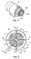
- Figur 1
- zeigt die isometrische Ansicht einer Ausführungsform der vorliegenden Erfindung mit drei FräsWerkzeugen;
- Figur 2
- zeigt die Bearbeitungsvorrichtung aus
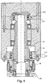
Figur 1 in einer Draufsicht auf die Fräswerkzeuge; - Figur 3
- zeigt die Bearbeitungsvorrichtung aus
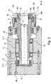
Figur 1 in einer Schnittansicht der Linie vom III - III inFigur 2 ; - Figur 4
- zeigt die Bearbeitungsvorrichtung aus
Figur 1 in einer Schnittansicht der Linie vom IV - IV inFigur 2 ; - Figur 5
- zeigt die Bearbeitungsvorrichtung aus
Figur 1 in einer Schnittansicht der Linie vom V - V inFigur 2 . - Im Folgenden werden die Richtungsangaben "oben" und "unten" verwendet, wobei "unten" die Seite der der Antriebsspindeln in deren Axialrichtung bezeichnet, auf der die Werkzeuge (die Fräse) angeordnet sind. Die gegenüberliegende Richtung wird mit "oben" bezeichnet.
- Die Erfindung betrifft eine Mehrprofilfräsvorrichtung für bevorzugt plattenförmige Werkstücke aus Holz, Holzwerkstoffen und/oder Kunststoffen, die für die Bearbeitung der Schmalseiten bzw. der Kanten der Schmalseiten vorgesehen ist.
- Die Vorrichtung enthält ein Motorgehäuse 11, 9, in dem eine Wicklung (nicht gezeigt) vorgesehen ist. Vorliegend ist das Gehäuse mehrteilig mit den Gehäuseteilen 11.1 und 11.2 des Hauptgehäuses 11 und einem Deckel 9 ausgeführt, jedoch kann eine entsprechende Konstruktion selbstverständlich auch als ein einzelnes Hauptgehäuseteil 11 mit Deckel 9 ausgeführt werden.
- In diesem Gehäuse 11, 9 ist eine axial feste Antriebsspindel 1, bevorzugt eine Hohlspindel (Hohlwelle) an Kugellagern 22 gelagert. An der Antriebsspindel 1 ist entsprechend zu den Statorwicklungen im Gehäuseteil 11.1 ein Rotor 10 befestigt, der durch die im Gehäuse 11 integrierten Wicklungen angetrieben wird. Der Stator im Gehäuse 11 und der Rotor an der Antriebsspindel 1 bilden somit einen Motor aus für die Antriebsspindel 1 aus. Die erste Antriebsspindel 1 ist in dieser Ausführungsform eine direkt vom Motor angetriebene Welle oder Hohlwelle, die zumindest das erste Werkzeug W1 antreibt.
- Die Antriebsspindel 1 ist in Bezug auf das Gehäuse 11 axial fest gelagert, indem die Gehäuseteile 11.1 und 11.2 in Verbindung mit der Antriebsspindel 1 entsprechend ausgebildet sind (siehe bspw.
Figur 3 ). In einer Ausführungsform mit einem einstückigen Gehäuse 11, können die Lager 22 auch mit Sprengringen oder anderen herkömmlichen Mitteln in Axialrichtung befestigt werden. - An dieser axial festen Spindel 1 ist ein erstes Werkzeug W1 befestigt, das einen ersten Fräsabschnitt F1 mit einem ersten Profil, beispielsweise einen Radius R3 (3mm), aufweist. Dieses Werkzeug W1 ist vorzugsweise mit einem Befestigungsmittel 21, insbesondere Schrauben, an der Stirnseite der axial festen Spindel 1 befestigt (siehe
Figuren 3 und4 ). Das Werkzeug W1 befindet sich in einer Arbeitstellung und fräst im Betrieb an einem vorbeilaufenden Werkstück eine Kante der Schmalseite auf das entsprechende Werkstückprofil (vorliegend z.B. auf R3). - Eine zweite Spindel 2 (Welle), die eine verschiebbare Hohlspindel (Hohlwelle) ist, ist an der axial festen Spindel 1 so gelagert, dass sie in Axialrichtung relativ zur ersten Antriebsspindel 1 verschiebbar ist. An der zweiten Spindel 2 ist ein zweites Werkzeug W2 drehfest befestigt, das einen zweiten Fräsabschnitt F2 mit einem zweiten Bearbeitungsprofil aufweist, in der vorliegenden Ausführungsform ein zweiter Radius R2 (2mm). Bevorzugt wird das zweite Werkzeug W2 an der Stirnseite der zweiten Hohlspindel 2 mit Befestigungsmitteln 27 befestigt, insbesondere mittels Schrauben. Vorzugsweise ist die zweite Spindel 2 drehfest mit der ersten Antriebsspindel 1 verbunden, so dass sie sich mit der ersten Antriebsspindel 1 im Gleichlauf befindet. Vorliegend wird eine solche Verbindung der zweiten Hohlspindel 2 mit der ersten Antriebsspindel 1 über einen Mitnehmerstift 16 realisiert (siehe
Figur 4 ). Es sind aber auch andere Verbindungen denkbar, bspw. über ein formschlüssiges Innenoder Außenprofil der (Antriebs-)Spindeln 1 und 2. Ebenfalls wäre denkbar, dass die Spindel 2 einen eigenen Rotor aufweist, der auch von den Statorwicklungen im Gehäuse angetrieben wird, möglicherweise auch von eigenen Statorwicklungen, die extra für den Rotor der zweiten Spindel 2 vorgesehen sind (die dann auch eine Antriebsspindel wäre). - Die axiale Verschiebbarkeit wird über die Bewegungseinrichtungen gesteuert. Vorliegend ist das ein Schiebezylinder 5 mit dem die Spindel 2 verbunden ist. Der Schiebezylinder 5 wird über eine pneumatische Leitung 26 axial verschoben. Der Schiebezylinder 5 für die Hohlspindel 2 und somit für das Werkzeug W2 ist in einem Verschieberaum angeordnet und ist in den
Figuren 3 und4 in seiner zurückgezogenen Position zu sehen. Der Schiebezylinder 5 ist bevorzugt drehfest im Gehäuse 11, 9 angeordnet, so dass sich der Schiebezylinder nur in axialer Richtung, aber nicht in Umfangsrichtung drehen kann. Beispielsweise können eine oder mehrere axial verlaufende Nuten im Gehäuse vorgesehen sein, in die ein Vorsprung 5.1 des Schiebezylinders eingreift. Es ist aber ebenfalls möglich, dass der Schiebezylinder 5 rotationssymmetrisch ausgestaltet ist, und seine Reibung mit der Gehäusewand eine Bewegung in Umfangsrichtung (also eine Drehung) verhindert. Der Vorsprung kann in diesem Fall ein Bereich mit einem größeren Durchmesser sein, der um den gesamten Umfang des Zylinders 5 vorgesehen ist. Wie oben erwähnt wird der Schiebezylinder 5 vorliegend mit Hilfe von Druckluft, die über eine Druckleitung 26 in den Verschieberaum geleitet wird, axial verschoben. An der Außenseite des Schiebezylinders 5 ist daher eine Dichtlippe 5.2, bspw. ein Gummiring, vorgesehen, der zwischen dem Gehäuse 11, 9 (vorliegend im Teilgehäuse 11.2) und dem Schiebezylinder 5 abdichtet und dafür sorgt, dass keine Leckage entsteht. Diese Dichtlippe erhöht auch bei einem rotationssymmetrischen Zylinder die Reibung, die einer Drehung des Schiebezylinders entgegenwirkt. Der Schiebezylinder 5 für die Hohlspindel 2 und somit für das Werkzeug W2 ist in seinem Verschieberaum in denFiguren 3 und4 in seiner zurückgezogenen Position zu sehen. Da sich die Spindel 2 des Werkzeugs W2 dreht, der Schiebezylinder 5 jedoch nicht, ist der Schiebezylinder in Umfangsrichtung über eine Lagerung 23 von der Spindel 2 entkoppelt. Die Lagerung 23 ist jedoch im Schiebezylinder 5 und in Bezug auf die Spindel in Axialrichtung fixiert, so dass die Verschiebekraft an die Spindel 2 übertragen werden kann. Die Lagerung wird vorliegend durch Kugellager realisiert, kann aber wie alle anderen Lagerungen in dieser Beschreibung durch andere übliche Lagerformen ersetzt werden, die für die notwendige Axialkraftübertragung geeignet sind. - Die zweite Spindel ist also bevorzugt zwischen einer Bewegungseinrichtung, bevorzugt dem Schiebezylinder 5, und dem zweiten Werkzeug W2 angeordnet.
- In der vorliegenden Ausführungsform ist der Schiebezylinder 5 oben im Gehäuse 11, 9 angeordnet, während die Spindel 2 für das Werkzeug W2 unten im Gehäuse 11 angeordnet ist, wobei sich in Axialrichtung dazwischen der Motor befindet. Dadurch kann in dieser Ausführungsform der Schiebezylinder 5 nicht direkt über die Lagerung 23 mit der Spindel 2 verbunden werden. Deshalb ist vorliegend die erste axialfeste Antriebsspindel 1 für das erste Werkzeug W1 als Hohlspindel ausgebildet. In dieser Hohlspindel 1 ist eine weitere Welle, vorzugsweise eine Hohlwelle, angeordnet, die oben mit dem Schiebezylinder 5 über die Lagerung verbunden ist. Unten wird die Axialbewegung bevorzugt über den oder die Mitnehmerstift(e) 16 auf die Spindel 2 übertragen. Es können jedoch auch separate Übertragungsmittel vorgesehen sein, oder die Welle 6 einstückig mit der Spindel 2 ausgebildet sein.
- Wird nun über den Kanal 26 Fluid (z.B. Luft oder ein Hydrauliköl) hinter den Schiebezylinder 5 gebracht, wird dessen Kolbenfläche, die sich auf der Seite des Fluidkanals 26 des Vorsprungs 5.1 befindet, des mit Luft beaufschlagt. Dadurch verschiebt sich der Schiebezylinder 5, bis sein Anschlag 5.1 gegen einen komplementären Anschlag im Gehäuse 11, 9 anschlägt (siehe
Figuren 3 bis 5 ). Dadurch wird das Werkzeug W2 von der zurückgezogenen Position in Ruhestellung, in die vorgeschobene Position der Arbeitsstellung gebracht. Um den Schiebezylinder 5 für die Spindel 2 zurückzuziehen, kann auf der gegenüber liegenden Seite der Fluidleitung 26 eine Feder sein, die Schiebezylinder so vorspannt, dass beim Nachlassen des Drucks über dem Schiebezylinder 5 dieser axial zurückgezogen wird, so dass das Werkzeug W2 wieder aus der Arbeitsstellung in die Leerlaufstellung gebracht wird. Bevorzugt ist jedoch, dass eine separate Druckleitung (nicht gezeigt) in den Verschieberaum unter den Schiebezylinder 5 führt, der dann mit Druck beaufschlagt wird und den Schiebezylinder 5 so wieder in Leerlaufstellung bringt. Auch eine Erzeugung von Vakuum im oben liegenden Fluidkanal kann ausreichen, so dass auf ein zusätzliches Element verzichtet werden könnte und nur der Fluidkanal 26 vorgesehen ist. Ebenfalls ist es möglich, dass der Schiebezylinder 5 über Magnetventile gesteuert wird, so dass die Verschiebung des Schiebezylinders 5 magnetisch erfolgt. Dazu sollten dann im Gehäuse 11, 9 entsprechende Elemente vorgesehen werden (in der vorliegenden Ausführungsform nicht gezeigt), wobei entweder zwei verschiedene elektromagnetische Zustände für die Leerlaufstellung und die Arbeitsstellung pro Schiebezylinder vorgesehen sind, oder die Schiebezylinder mit einer Feder in Leerlaufstellung vorgespannt sind und die elektromagnetische Kraft die Schiebezylinder, bzw. die Werkzeuge nur in Arbeitsstellung und die Federkraft wieder zurück in die Leerlaufstellung bringen. - In der vorliegenden Ausführungsform ist es ferner ein drittes Werkzeug W3 mit einem dritten Bearbeitungsprofil, vorliegend Radius R1,5 (1,5mm), vorgesehen. Das dritte Werkzeug W3 sitzt auf einer verschiebbaren Spindel 3, die als Hohlspindel ausgebildet ist und von zur verschiebbaren Spindel 2 verschieden ist. Vorliegend ist die verschiebbare Spindel 3 in Axialrichtung über der verschiebbaren Spindel 2 angeordnet und wird über einen Schiebezylinder 4 von der. Leerlaufstellung in die Arbeitsstellung gebracht (in den
Figuren 3 bis 5 ist die Spindel 3 in Arbeitsstellung gezeigt). Dazu ist in der vorliegenden Ausführungsform ein Fluidkanal 24 vorgesehen, der den Schiebezylinder 4 in die Arbeitsstellung bringt (sieheFiguren 3 und4 ). Die Steuerung und die Ausgestaltung des Schiebezylinders 4 wird bevorzugt analog zur oben beschriebenen Steuerung und Konstruktion des Schiebezylinders 5 durchgeführt, einschließlich der Ausgestaltung des Schiebezylinders 4 mit einem Vorsprung 4.1 und Dichtlippe 4.2. Gleiches gilt für das Zurückführen in die Leerlaufstellung, das entweder durch Unterdruck in der Fluidleitung, durch eine Vorspannfeder, die eine Kraft in Richtung der Leerlaufstellung aufbringen kann, oder durch einen zusätzlichen Druckkanal unter den Schiebezylinder 4 geschehen kann. Eine magnetische ist ebenfalls möglich. Die dritte Spindel ist also bevorzugt zwischen einer Bewegungseinrichtung, bevorzugt dem Schiebezylinder 4, und dem dritten Werkzeug W3 angeordnet. - Die verschiebbare Spindel 3 weist einen Mitnehmerstift auf (einstückig oder als separates Element), der durch die axial feste Spindel 1 hindurchgeht und so die Rotation der axial festen Spindel übernimmt. Das Werkzeug W3 ist ebenfalls bevorzugt mit Befestigungsmitteln an der Stirnseite der verschiebbaren Spindel 3 befestigt, wobei die Befestigungsmittel bevorzugt Schrauben sind.
- Die verschiebbaren Spindeln 2 und 3 drehen sich jeweils mit der axial festen Spindel, wobei die Schiebezylinder 4 und 5 sich nur axial bewegen und jeweils über Kugellager 23, 25 mit den jeweiligen Spindeln 2 und 3 verbunden sind.
- Der Durchmesser D (dargestellt in
Figur 2 ) der jeweiligen Fräsabschnitte F1, F2, F3 der Werkzeuge W1, W2, W3 (usw.), der den Abstand zwischen den Schneidprofilen anzeigt, ist gleich, so dass das engere Profil mit Radius R2 des Werkzeugs W2 das Profil mit Radius R3 des Werkzeugs W1 überlagert, wenn sich beide in Arbeitstellung befinden. Die Mehrprofilfräsvorrichtung ist also derart eingerichtet, dass das Bearbeitungsprofil des zweiten Fräswerkzeugs das Bearbeitungsprofil des ersten Werkzeugs so überlagert, dass das bearbeitete Werkstück das zweite Bearbeitungsprofil erhält, wenn sich die zweite Fräseinrichtung in der Arbeitsstellung befindet. So wird sichergestellt, dass, obwohl beide Werkzeuge gleichzeitig ein Werkstück bearbeiten, nur das Profil des Werkzeugs W2 auf das bearbeitete Werkstück übertragen wird. Das Werkzeug W3 besitzt vorzugsweise ein Bearbeitungsprofil, das sowohl das Bearbeitungsprofil des Werkzeugs W1 als auch des zweiten Werkzeugs W2 überlagert. - Generell wird dann je nach gewünschtem Bearbeitungsprofil nur das Werkzeug W1, auch das Werkzeug W2 oder zusätzlich das Werkzeug W3 in Arbeitsstellung gebracht. In einer anderen bevorzugten Ausführungsform wird das Werkzeug W2 zurückgezogen, wenn das Werkzeug W3 in Arbeitstellung gebracht wird, so dass das Werkzeug W3 nur das Bearbeitungsprofil des Werkzeugs W1 überlagert. Vorteilhaft ist außerdem, dass sich die Werkzeuge W2 and W3 vorliegend immer zusammen mit dem Werkzeug W1 drehen, so dass während der Bearbeitung das Bearbeitungsprofil umgestellt werden kann, ohne das die Maschine angehalten werden muss. Dies wird zum Einen durch die Schiebezylinder ermöglicht, die axial zusammen mit den verschiebbaren Spindeln fixiert sind, die jedoch in Umlaufrichtung relativ zu den Hohlspindeln bewegbar sind, bzw. keine eigene Drehung in Bezug auf das Gehäuse aufweisen. Zum Anderen durch die Drehfeste Verbindung (Mitnehmerstifte 15, 16) der axial beweglichen Spindeln 2, 3 mit der axialfesten Antriebsspindel 1.
- Wenn, wie oben erwähnt, für jede Antriebsspindel 1, 2, 3 ein eigener Rotor vorgesehen ist, dann muss sich die jeweilige Antriebsspindel nicht mit der ersten Antriebsspindel 1 mitdrehen, und die Mitnehmerstifte können weggelassen werden, wenn sie nur zum Aufnehmen der Rotation vorgesehen sind. Die jeweiligen Antriebsspindeln 2, 3 können dann in einer Ruhestellung sein und bei Bedarf in einen Leerlauf geschaltet werden. Danach, also wenn die Antriebsspindeln 2, 3 mit der ersten Antriebsspindel 1 im Gleichlauf sind, kann dann das entsprechende Werkzeug W2, W3 in Arbeitsstellung gebracht werden.
- Die einzelnen Fräswerkzeuge mit unterschiedlichen Bearbeitungsprofilen sind jeweils koaxial angeordnet und weisen Fräsabschnitte F1, F2, F3 auf, mit den jeweiligen Bearbeitungsprofilen. Wie oben erwähnt, sind die einzelnen Werkzeuge jeweils an den zugehörigen (Antriebs-)spindeln 1, 2, 3 befestigt, bevorzugt jeweils an deren Stirnseite. Die Befestigungsmittel 21, 27, 28 sind dabei vorzugsweise Schrauben, wobei die Befestigungsmittel bevorzugt außermittig angeordnet sind, so dass durch die Rotation der (Antriebs) spindel 1, 2, 3 und der Werkzeuge W1, W2, W3 sich die Befestigungsmittel nicht aus Versehen öffnen können.
- Generell muss, wenn ein beliebiges Werkzeug ausgetauscht werden soll, zunächst das erste Werkzeug W1 abgenommen werden, so dass auf das zweite Werkzeug W2 zugegriffen werden kann (siehe
Figuren 2 und3 ). Es gilt dasselbe, wenn das Werkzeug W3 ausgetauscht werden soll, für das Werkzeug W2. Das heißt, das Werkzeug W2.muss entfernt werden, bevor das Werkzeug W3 abgenommen werden kann. Dann wird das entsprechende Werkzeug ausgetauscht und wieder in umgekehrter Reihenfolge an der Bearbeitungsvorrichtung jeweils an den zugehörigen Hohlspindeln befestigt. - Es ist jedoch möglich, zumindest ein zweites Werkzeug W2 so auszubilden, dass es in seinem Hauptkörper ein Loch mit einem Durchmesser aufweist, der größer ist als der Außendurchmesser des ersten Werkzeugs (inkl. der Fräsabschnitte F1). Da das erste Werkzeug, wie in
Figur 2 zu sehen ist, aus einem Hauptkörper H1 und den Fräsabschnitten F1 ausgebildet ist, die sich vorliegend in gleichen Abständen radial nach Außen von dem Hauptkörper H1 erstrecken, könnte bei einem Werkzeug W2, dessen Hauptkörper H2 das Loch mit einem Innendurchmesser aufweist, der größer als der Außendurchmesser der Fräsabschnitte F1 ist, auch abgenommen werden, ohne dass das Werkzeug W1 zuerst abgenommen werden müsste. Lediglich bei drei oder mehr Werkzeugen lässt es sich nicht vermeiden, dass für das dritte Werkzeug W3 (und jedes weitere) zumindest das erste oder zweite Werkzeug W1, W2 abgenommen werden müsste, solange die Fräsabschnitte, bzw. das Schneidprofil den gleichen Durchmesser D aufweisen sollen. Fällt diese Anforderung weg, kann man die Fräswerkzeuge W1, W2, W3, usw. jeweils mit einem Hauptkörper H1, H2, H3 so mit einer Aussparung, bzw. einem Loch ausbilden, dass sie immer einzeln abgenommen werden können.
Claims (7)
- Mehrprofilfräsvorrichtung zur spanenden Bearbeitung von bevorzugt plattenförmigen Werkstücken aus Holz, Holzwerkstoffen und/oder Kunststoffen, insbesondere zur Bearbeitung der Kanten der Schmalseiten der Werkstücke, umfassend:eine erste Fräseinrichtung, die ein erstes Fräswerkzeug (W1) mit einem ersten Bearbeitungsprofil und eine erste Antriebsspindel (1) aufweist, wobei die erste Fräseinrichtung in einer Arbeitsstellung angeordnet ist;zumindest eine zweite Fräseinrichtung, die ein zweites Fräswerkzeug (W2) mit einem zweiten Bearbeitungsprofil aufweist und die zwischen einer Arbeitsstellung und einer Leerlauf-/Ruhestellung bewegbar ist; ein Motor (10) zum Antreiben der ersten Antriebsspindel (1);eine Bewegungseinrichtung (5, 26), welche zum Bewegen zumindest der zweiten Fräseinrichtung zwischen der Arbeitsstellung und der Leerlaufstellung eingerichtet ist;ein Gehäuse (9, 11), in dem die Fräseinrichtungen, die Bewegungseinrichtung (5, 26) und der Motor (10) aufgenommen sind;die zweite Fräseinrichtung, zumindest eine zweite Spindel (2) aufweist, wobei die zweite Fräseinrichtung koaxial mit der ersten Fräseinrichtung angeordnet ist,dadurch gekennzeichnet, dassdie Bewegungseinrichtung (5, 26) in Axialrichtung an der den Fräswerkzeugen (W1, W2) gegenüberliegenden Seite des Motors (10) angeordnet ist und über eine Welle (6), insbesondere Hohlwelle, die in der ersten Antriebsspindel (1) angeordnet ist, mit der Spindel (2) verbunden ist oder die Welle (6) einstückig mit der Spindel (2) ausgebildet ist.
- Mehrprofilfräsvorrichtung nach Anspruch 1, bei der die Bewegungseinrichtung (elektro-)pneumatisch, (elektro-) hydraulisch und/oder (elektro-)magnetisch bewegt wird.
- Mehrprofilfräsvorrichtung nach Anspruch 1 oder 2, die eine dritte Fräseinrichtung aufweist, die ein drittes Fräswerkzeug (W3) mit einem dritten Bearbeitungsprofil und eine dritte Spindel (3) aufweist, wobei die dritte Fräseinrichtung koaxial mit der ersten Fräseinrichtung angeordnet ist und die dritte Fräseinrichtung zwischen der Arbeitsstellung und einer Leerlauf-/Ruhestellung axial zur ersten Fräseinrichtung relativ bewegbar ist.
- Mehrprofilfräsvorrichtung nach Anspruch 3, bei der das Bearbeitungsprofil des dritten Fräswerkzeugs (W3) das Bearbeitungsprofil des ersten und zweiten Fräswerkzeugs (W1, W2) so überlagert, dass das bearbeitete Werkstück das dritte Bearbeitungsprofil erhält, wenn sich die dritte Fräseinrichtung in der Arbeitsstellung befindet.
- Mehrprofilfräsvorrichtung nach einem der Ansprüche 3 oder 4, bei der die zweite und die dritte Fräseinrichtung so eingerichtet sind, dass sie nicht zusammen in der Arbeitsstellung sind oder bei der die zweite und die dritte Fräseinrichtung so eingerichtet sind, dass sie zusammen in der Arbeitsstellung sind.
- Mehrprofilfräsvorrichtung nach einem der vorhergehenden Ansprüche, bei der zumindest eine der (Antriebs-)Spindeln (1, 2, 3) als Hohlprofilwelle ausgestaltet ist.
- Mehrprofilfräsvorrichtung nach einem der vorhergehenden Ansprüche, bei der die Drehung der ersten Antriebsspindel (1) über einen oder mehrere Mitnehmerstift(e) (15, 16) auf die andere(n) Spindel(n) übertragen wird und/oder bei der die andere(n) Antriebsspindel(n) über einen oder mehrere separate Motoren angetrieben werden.
Applications Claiming Priority (1)
| Application Number | Priority Date | Filing Date | Title |
|---|---|---|---|
| DE102011004536A DE102011004536A1 (de) | 2011-02-22 | 2011-02-22 | Fräsmotor mit mehreren Spindeln und einzeln austauschbaren Werkzeugen |
Publications (3)
| Publication Number | Publication Date |
|---|---|
| EP2492071A2 EP2492071A2 (de) | 2012-08-29 |
| EP2492071A3 EP2492071A3 (de) | 2014-06-25 |
| EP2492071B1 true EP2492071B1 (de) | 2016-10-26 |
Family
ID=45656031
Family Applications (1)
| Application Number | Title | Priority Date | Filing Date |
|---|---|---|---|
| EP12155932.2A Active EP2492071B1 (de) | 2011-02-22 | 2012-02-17 | Fräsmotor mit mehreren Spindeln |
Country Status (5)
| Country | Link |
|---|---|
| EP (1) | EP2492071B1 (de) |
| CN (1) | CN102649284B (de) |
| BR (1) | BR102012003854B1 (de) |
| DE (1) | DE102011004536A1 (de) |
| ES (1) | ES2610961T3 (de) |
Cited By (1)
| Publication number | Priority date | Publication date | Assignee | Title |
|---|---|---|---|---|
| EP3944939A1 (de) | 2020-07-31 | 2022-02-02 | Ledermann GmbH & Co. KG | Werkzeugeinheit und schaltbares werkzeugsystem für eine solche werkzeugeinheit |
Families Citing this family (10)
| Publication number | Priority date | Publication date | Assignee | Title |
|---|---|---|---|---|
| DE102013226214A1 (de) | 2013-12-17 | 2015-06-18 | Homag Holzbearbeitungssysteme Gmbh | Bearbeitungsvorrichtung |
| DE202014011134U1 (de) | 2014-06-03 | 2018-01-18 | Leitz Gmbh & Co. Kg | Fräswerkzeug |
| DE102014008033B4 (de) | 2014-06-03 | 2018-03-29 | Leitz Gmbh & Co. Kg | Fräswerkzeug |
| CN104842423A (zh) * | 2015-05-19 | 2015-08-19 | 朱德金 | 一种杆状物料旋切机构 |
| CN104890077A (zh) * | 2015-06-05 | 2015-09-09 | 李广连 | 一种齿轮驱动式木板旋割座 |
| CN105773771A (zh) * | 2016-05-06 | 2016-07-20 | 博艳萍 | 一种手摇式旋切轮驱动机构 |
| PT3354386T (pt) | 2017-01-25 | 2021-03-24 | Ledermann Gmbh & Co Kg | Cabeça porta-ferramenta e sistema de ferramentas com uma cabeça porta-ferramenta |
| DE102017123681C5 (de) * | 2017-10-11 | 2022-01-27 | Leitz Gmbh & Co. Kg | Fräswerkzeug zum Bearbeiten von Holz, Holzwerkstoffen, Kunststoffen oder Leichtmetallen |
| DE202017007479U1 (de) | 2017-10-11 | 2022-01-28 | LEITZ GmbH & Co.KG | Fräswerkzeug zum Bearbeiten von Holz, Holzwerkstoffen, Kunststoffen oder Leichtmetallen |
| CN114523532B (zh) * | 2022-01-20 | 2022-08-19 | 顺德职业技术学院 | 一种木工加工用的刀具定位装置 |
Family Cites Families (10)
| Publication number | Priority date | Publication date | Assignee | Title |
|---|---|---|---|---|
| DE2321292A1 (de) * | 1973-04-27 | 1974-11-14 | Weniger & Co | Vorrichtung zur kantenreinigung von beidseitig beschichteten spanplatten od. dgl |
| US3901295A (en) * | 1974-10-15 | 1975-08-26 | Dart Ind Inc | Trimming apparatus |
| CN2115877U (zh) * | 1992-02-18 | 1992-09-16 | 傅敬中 | 一种香芯机 |
| JPH1128704A (ja) * | 1997-07-09 | 1999-02-02 | Kanefusa Corp | 刃先にランドを有するフライス |
| DE19915672C2 (de) * | 1999-04-07 | 2002-05-29 | Homag Maschinenbau Ag | Vorrichtung zum Bearbeiten von Kanten eines plattenförmigen Werkstückes mit mehreren Spanwerkzeugen |
| DE10341463A1 (de) * | 2003-09-09 | 2005-04-21 | Ledermann & Co | Fräsaggregat und Verfahren zur Kantenbearbeitung von plattenförmigen Werkstücken |
| ITMO20070226A1 (it) | 2007-07-06 | 2009-01-07 | Scm Group Spa | Apparato per fresare |
| CN201309191Y (zh) * | 2008-11-04 | 2009-09-16 | 尤溪县三恒竹木制品有限公司 | 竹木产品外圆铣削机 |
| IT1398754B1 (it) * | 2010-03-02 | 2013-03-18 | Scm Group Spa | Apparato per fresare |
| DE202010010704U1 (de) * | 2010-07-27 | 2011-11-14 | Ledermann Gmbh & Co. Kg | Bearbeitungsvorrichtung |
-
2011
- 2011-02-22 DE DE102011004536A patent/DE102011004536A1/de active Pending
-
2012
- 2012-02-17 ES ES12155932.2T patent/ES2610961T3/es active Active
- 2012-02-17 EP EP12155932.2A patent/EP2492071B1/de active Active
- 2012-02-22 BR BR102012003854-4A patent/BR102012003854B1/pt not_active IP Right Cessation
- 2012-02-22 CN CN201210042115.8A patent/CN102649284B/zh active Active
Non-Patent Citations (1)
| Title |
|---|
| None * |
Cited By (2)
| Publication number | Priority date | Publication date | Assignee | Title |
|---|---|---|---|---|
| EP3944939A1 (de) | 2020-07-31 | 2022-02-02 | Ledermann GmbH & Co. KG | Werkzeugeinheit und schaltbares werkzeugsystem für eine solche werkzeugeinheit |
| US11701718B2 (en) | 2020-07-31 | 2023-07-18 | Ledermann Gmbh & Co. Kg | Tool unit and switchable tool system for a tool unit |
Also Published As
| Publication number | Publication date |
|---|---|
| BR102012003854B1 (pt) | 2021-03-23 |
| EP2492071A3 (de) | 2014-06-25 |
| DE102011004536A1 (de) | 2012-08-23 |
| BR102012003854A2 (pt) | 2013-11-05 |
| EP2492071A2 (de) | 2012-08-29 |
| ES2610961T3 (es) | 2017-05-04 |
| CN102649284A (zh) | 2012-08-29 |
| CN102649284B (zh) | 2016-01-20 |
Similar Documents
| Publication | Publication Date | Title |
|---|---|---|
| EP2492071B1 (de) | Fräsmotor mit mehreren Spindeln | |
| EP2603340B1 (de) | Werkzeughalter | |
| DE102017121294B4 (de) | Spindeleinheit für Werkzeugmaschinen | |
| EP0970770A1 (de) | Einrichtung sowie Verfahren zur Bearbeitung von Bohrungen | |
| DE112007001338T5 (de) | Drehschieberpumpe zum Pumpen von Hydraulikfluid | |
| DE19525343A1 (de) | Vorrichtung zum Überführen von Fluid zwischen relativ zueinander drehbaren Maschinenteilen | |
| EP2349622A1 (de) | Mehrschneidiges spanabhebendes bohrungs-nachbearbeitungswerkzeug | |
| WO2018046036A2 (de) | Mehrschneidiges zerspanungswerkzeug und verfahren zum bearbeiten einer lagergasse | |
| DE4341167A1 (de) | Einrichtung zur Übertragung eines Druckmediums | |
| DE2501020A1 (de) | Klemmkupplung zum starren verbinden einer antriebsbuchse mit einer darin verschiebbar gefuehrten spindel | |
| WO2017140499A1 (de) | Gleichgangzylinder für strangpressanlagen | |
| DE102009033528A1 (de) | Kombinationswerkzeug | |
| EP1360135A1 (de) | Falzmesserzylinder eines falzapparates und ein verfahren zum verstellen eines falzmessers | |
| DE2340125A1 (de) | Maschine zum profilwalzen von ringen | |
| DE2028932A1 (de) | Schaltvorrichtung insbesondere fur Bohr spindeln | |
| EP3509780B1 (de) | Schneidenträger und zerspanungswerkzeug mit einem schneidenträger | |
| DE3613882C1 (de) | Mehrspindel-Drehmaschine | |
| EP0974782B1 (de) | Druckmittelzuführungseinrichtung | |
| EP1163976A1 (de) | Drehantrieb mit einer Drehzahlumschalteinrichtung für eine Werkzeughaltevorrichtung | |
| DE4008204C2 (de) | ||
| EP3357636A1 (de) | Werkzeugmodul zur feinbearbeitung | |
| DE399114C (de) | Flaechenschleifmaschine | |
| EP1574275A2 (de) | Spannzylinder | |
| DE2953287A1 (en) | Motion translation apparatus | |
| DE2709448B2 (de) | Bohrspindeleinheit |
Legal Events
| Date | Code | Title | Description |
|---|---|---|---|
| PUAI | Public reference made under article 153(3) epc to a published international application that has entered the european phase |
Free format text: ORIGINAL CODE: 0009012 |
|
| AK | Designated contracting states |
Kind code of ref document: A2 Designated state(s): AL AT BE BG CH CY CZ DE DK EE ES FI FR GB GR HR HU IE IS IT LI LT LU LV MC MK MT NL NO PL PT RO RS SE SI SK SM TR |
|
| AX | Request for extension of the european patent |
Extension state: BA ME |
|
| PUAL | Search report despatched |
Free format text: ORIGINAL CODE: 0009013 |
|
| AK | Designated contracting states |
Kind code of ref document: A3 Designated state(s): AL AT BE BG CH CY CZ DE DK EE ES FI FR GB GR HR HU IE IS IT LI LT LU LV MC MK MT NL NO PL PT RO RS SE SI SK SM TR |
|
| AX | Request for extension of the european patent |
Extension state: BA ME |
|
| RIC1 | Information provided on ipc code assigned before grant |
Ipc: B27G 13/00 20060101ALI20140522BHEP Ipc: B27D 5/00 20060101AFI20140522BHEP Ipc: B23C 3/12 20060101ALI20140522BHEP |
|
| 17P | Request for examination filed |
Effective date: 20141017 |
|
| RBV | Designated contracting states (corrected) |
Designated state(s): AL AT BE BG CH CY CZ DE DK EE ES FI FR GB GR HR HU IE IS IT LI LT LU LV MC MK MT NL NO PL PT RO RS SE SI SK SM TR |
|
| GRAP | Despatch of communication of intention to grant a patent |
Free format text: ORIGINAL CODE: EPIDOSNIGR1 |
|
| INTG | Intention to grant announced |
Effective date: 20160413 |
|
| GRAJ | Information related to disapproval of communication of intention to grant by the applicant or resumption of examination proceedings by the epo deleted |
Free format text: ORIGINAL CODE: EPIDOSDIGR1 |
|
| GRAR | Information related to intention to grant a patent recorded |
Free format text: ORIGINAL CODE: EPIDOSNIGR71 |
|
| GRAS | Grant fee paid |
Free format text: ORIGINAL CODE: EPIDOSNIGR3 |
|
| GRAA | (expected) grant |
Free format text: ORIGINAL CODE: 0009210 |
|
| INTC | Intention to grant announced (deleted) | ||
| RAP1 | Party data changed (applicant data changed or rights of an application transferred) |
Owner name: HOMAG GMBH |
|
| INTG | Intention to grant announced |
Effective date: 20160913 |
|
| AK | Designated contracting states |
Kind code of ref document: B1 Designated state(s): AL AT BE BG CH CY CZ DE DK EE ES FI FR GB GR HR HU IE IS IT LI LT LU LV MC MK MT NL NO PL PT RO RS SE SI SK SM TR |
|
| REG | Reference to a national code |
Ref country code: GB Ref legal event code: FG4D Free format text: NOT ENGLISH |
|
| REG | Reference to a national code |
Ref country code: CH Ref legal event code: EP |
|
| REG | Reference to a national code |
Ref country code: AT Ref legal event code: REF Ref document number: 839674 Country of ref document: AT Kind code of ref document: T Effective date: 20161115 |
|
| REG | Reference to a national code |
Ref country code: IE Ref legal event code: FG4D Free format text: LANGUAGE OF EP DOCUMENT: GERMAN |
|
| REG | Reference to a national code |
Ref country code: DE Ref legal event code: R096 Ref document number: 502012008611 Country of ref document: DE |
|
| REG | Reference to a national code |
Ref country code: LT Ref legal event code: MG4D |
|
| PG25 | Lapsed in a contracting state [announced via postgrant information from national office to epo] |
Ref country code: LV Free format text: LAPSE BECAUSE OF FAILURE TO SUBMIT A TRANSLATION OF THE DESCRIPTION OR TO PAY THE FEE WITHIN THE PRESCRIBED TIME-LIMIT Effective date: 20161026 |
|
| REG | Reference to a national code |
Ref country code: NL Ref legal event code: MP Effective date: 20161026 |
|
| PG25 | Lapsed in a contracting state [announced via postgrant information from national office to epo] |
Ref country code: NO Free format text: LAPSE BECAUSE OF FAILURE TO SUBMIT A TRANSLATION OF THE DESCRIPTION OR TO PAY THE FEE WITHIN THE PRESCRIBED TIME-LIMIT Effective date: 20170126 Ref country code: SE Free format text: LAPSE BECAUSE OF FAILURE TO SUBMIT A TRANSLATION OF THE DESCRIPTION OR TO PAY THE FEE WITHIN THE PRESCRIBED TIME-LIMIT Effective date: 20161026 Ref country code: GR Free format text: LAPSE BECAUSE OF FAILURE TO SUBMIT A TRANSLATION OF THE DESCRIPTION OR TO PAY THE FEE WITHIN THE PRESCRIBED TIME-LIMIT Effective date: 20170127 Ref country code: LT Free format text: LAPSE BECAUSE OF FAILURE TO SUBMIT A TRANSLATION OF THE DESCRIPTION OR TO PAY THE FEE WITHIN THE PRESCRIBED TIME-LIMIT Effective date: 20161026 |
|
| REG | Reference to a national code |
Ref country code: ES Ref legal event code: FG2A Ref document number: 2610961 Country of ref document: ES Kind code of ref document: T3 Effective date: 20170504 |
|
| PG25 | Lapsed in a contracting state [announced via postgrant information from national office to epo] |
Ref country code: NL Free format text: LAPSE BECAUSE OF FAILURE TO SUBMIT A TRANSLATION OF THE DESCRIPTION OR TO PAY THE FEE WITHIN THE PRESCRIBED TIME-LIMIT Effective date: 20161026 Ref country code: FI Free format text: LAPSE BECAUSE OF FAILURE TO SUBMIT A TRANSLATION OF THE DESCRIPTION OR TO PAY THE FEE WITHIN THE PRESCRIBED TIME-LIMIT Effective date: 20161026 Ref country code: RS Free format text: LAPSE BECAUSE OF FAILURE TO SUBMIT A TRANSLATION OF THE DESCRIPTION OR TO PAY THE FEE WITHIN THE PRESCRIBED TIME-LIMIT Effective date: 20161026 Ref country code: HR Free format text: LAPSE BECAUSE OF FAILURE TO SUBMIT A TRANSLATION OF THE DESCRIPTION OR TO PAY THE FEE WITHIN THE PRESCRIBED TIME-LIMIT Effective date: 20161026 Ref country code: PL Free format text: LAPSE BECAUSE OF FAILURE TO SUBMIT A TRANSLATION OF THE DESCRIPTION OR TO PAY THE FEE WITHIN THE PRESCRIBED TIME-LIMIT Effective date: 20161026 Ref country code: PT Free format text: LAPSE BECAUSE OF FAILURE TO SUBMIT A TRANSLATION OF THE DESCRIPTION OR TO PAY THE FEE WITHIN THE PRESCRIBED TIME-LIMIT Effective date: 20170227 Ref country code: IS Free format text: LAPSE BECAUSE OF FAILURE TO SUBMIT A TRANSLATION OF THE DESCRIPTION OR TO PAY THE FEE WITHIN THE PRESCRIBED TIME-LIMIT Effective date: 20170226 Ref country code: BE Free format text: LAPSE BECAUSE OF NON-PAYMENT OF DUE FEES Effective date: 20170228 |
|
| REG | Reference to a national code |
Ref country code: DE Ref legal event code: R097 Ref document number: 502012008611 Country of ref document: DE |
|
| PG25 | Lapsed in a contracting state [announced via postgrant information from national office to epo] |
Ref country code: CZ Free format text: LAPSE BECAUSE OF FAILURE TO SUBMIT A TRANSLATION OF THE DESCRIPTION OR TO PAY THE FEE WITHIN THE PRESCRIBED TIME-LIMIT Effective date: 20161026 Ref country code: RO Free format text: LAPSE BECAUSE OF FAILURE TO SUBMIT A TRANSLATION OF THE DESCRIPTION OR TO PAY THE FEE WITHIN THE PRESCRIBED TIME-LIMIT Effective date: 20161026 Ref country code: EE Free format text: LAPSE BECAUSE OF FAILURE TO SUBMIT A TRANSLATION OF THE DESCRIPTION OR TO PAY THE FEE WITHIN THE PRESCRIBED TIME-LIMIT Effective date: 20161026 Ref country code: DK Free format text: LAPSE BECAUSE OF FAILURE TO SUBMIT A TRANSLATION OF THE DESCRIPTION OR TO PAY THE FEE WITHIN THE PRESCRIBED TIME-LIMIT Effective date: 20161026 Ref country code: SK Free format text: LAPSE BECAUSE OF FAILURE TO SUBMIT A TRANSLATION OF THE DESCRIPTION OR TO PAY THE FEE WITHIN THE PRESCRIBED TIME-LIMIT Effective date: 20161026 |
|
| PG25 | Lapsed in a contracting state [announced via postgrant information from national office to epo] |
Ref country code: SM Free format text: LAPSE BECAUSE OF FAILURE TO SUBMIT A TRANSLATION OF THE DESCRIPTION OR TO PAY THE FEE WITHIN THE PRESCRIBED TIME-LIMIT Effective date: 20161026 Ref country code: BG Free format text: LAPSE BECAUSE OF FAILURE TO SUBMIT A TRANSLATION OF THE DESCRIPTION OR TO PAY THE FEE WITHIN THE PRESCRIBED TIME-LIMIT Effective date: 20170126 |
|
| PLBE | No opposition filed within time limit |
Free format text: ORIGINAL CODE: 0009261 |
|
| STAA | Information on the status of an ep patent application or granted ep patent |
Free format text: STATUS: NO OPPOSITION FILED WITHIN TIME LIMIT |
|
| PG25 | Lapsed in a contracting state [announced via postgrant information from national office to epo] |
Ref country code: MC Free format text: LAPSE BECAUSE OF FAILURE TO SUBMIT A TRANSLATION OF THE DESCRIPTION OR TO PAY THE FEE WITHIN THE PRESCRIBED TIME-LIMIT Effective date: 20161026 |
|
| REG | Reference to a national code |
Ref country code: CH Ref legal event code: PL |
|
| 26N | No opposition filed |
Effective date: 20170727 |
|
| GBPC | Gb: european patent ceased through non-payment of renewal fee |
Effective date: 20170217 |
|
| PG25 | Lapsed in a contracting state [announced via postgrant information from national office to epo] |
Ref country code: LI Free format text: LAPSE BECAUSE OF NON-PAYMENT OF DUE FEES Effective date: 20170228 Ref country code: CH Free format text: LAPSE BECAUSE OF NON-PAYMENT OF DUE FEES Effective date: 20170228 |
|
| REG | Reference to a national code |
Ref country code: IE Ref legal event code: MM4A |
|
| PG25 | Lapsed in a contracting state [announced via postgrant information from national office to epo] |
Ref country code: SI Free format text: LAPSE BECAUSE OF FAILURE TO SUBMIT A TRANSLATION OF THE DESCRIPTION OR TO PAY THE FEE WITHIN THE PRESCRIBED TIME-LIMIT Effective date: 20161026 |
|
| REG | Reference to a national code |
Ref country code: FR Ref legal event code: ST Effective date: 20171031 |
|
| PG25 | Lapsed in a contracting state [announced via postgrant information from national office to epo] |
Ref country code: LU Free format text: LAPSE BECAUSE OF NON-PAYMENT OF DUE FEES Effective date: 20170217 |
|
| PG25 | Lapsed in a contracting state [announced via postgrant information from national office to epo] |
Ref country code: FR Free format text: LAPSE BECAUSE OF NON-PAYMENT OF DUE FEES Effective date: 20170228 |
|
| REG | Reference to a national code |
Ref country code: BE Ref legal event code: MM Effective date: 20170228 |
|
| PG25 | Lapsed in a contracting state [announced via postgrant information from national office to epo] |
Ref country code: IE Free format text: LAPSE BECAUSE OF NON-PAYMENT OF DUE FEES Effective date: 20170217 Ref country code: GB Free format text: LAPSE BECAUSE OF NON-PAYMENT OF DUE FEES Effective date: 20170217 |
|
| PG25 | Lapsed in a contracting state [announced via postgrant information from national office to epo] |
Ref country code: MT Free format text: LAPSE BECAUSE OF FAILURE TO SUBMIT A TRANSLATION OF THE DESCRIPTION OR TO PAY THE FEE WITHIN THE PRESCRIBED TIME-LIMIT Effective date: 20161026 |
|
| PG25 | Lapsed in a contracting state [announced via postgrant information from national office to epo] |
Ref country code: HU Free format text: LAPSE BECAUSE OF FAILURE TO SUBMIT A TRANSLATION OF THE DESCRIPTION OR TO PAY THE FEE WITHIN THE PRESCRIBED TIME-LIMIT; INVALID AB INITIO Effective date: 20120217 |
|
| PG25 | Lapsed in a contracting state [announced via postgrant information from national office to epo] |
Ref country code: CY Free format text: LAPSE BECAUSE OF NON-PAYMENT OF DUE FEES Effective date: 20161026 |
|
| PG25 | Lapsed in a contracting state [announced via postgrant information from national office to epo] |
Ref country code: MK Free format text: LAPSE BECAUSE OF FAILURE TO SUBMIT A TRANSLATION OF THE DESCRIPTION OR TO PAY THE FEE WITHIN THE PRESCRIBED TIME-LIMIT Effective date: 20161026 |
|
| PG25 | Lapsed in a contracting state [announced via postgrant information from national office to epo] |
Ref country code: TR Free format text: LAPSE BECAUSE OF FAILURE TO SUBMIT A TRANSLATION OF THE DESCRIPTION OR TO PAY THE FEE WITHIN THE PRESCRIBED TIME-LIMIT Effective date: 20161026 |
|
| PG25 | Lapsed in a contracting state [announced via postgrant information from national office to epo] |
Ref country code: AL Free format text: LAPSE BECAUSE OF FAILURE TO SUBMIT A TRANSLATION OF THE DESCRIPTION OR TO PAY THE FEE WITHIN THE PRESCRIBED TIME-LIMIT Effective date: 20161026 |
|
| PGFP | Annual fee paid to national office [announced via postgrant information from national office to epo] |
Ref country code: ES Payment date: 20210303 Year of fee payment: 10 |
|
| REG | Reference to a national code |
Ref country code: ES Ref legal event code: FD2A Effective date: 20230428 |
|
| P01 | Opt-out of the competence of the unified patent court (upc) registered |
Effective date: 20230529 |
|
| PG25 | Lapsed in a contracting state [announced via postgrant information from national office to epo] |
Ref country code: ES Free format text: LAPSE BECAUSE OF NON-PAYMENT OF DUE FEES Effective date: 20220218 |
|
| PGFP | Annual fee paid to national office [announced via postgrant information from national office to epo] |
Ref country code: DE Payment date: 20250212 Year of fee payment: 14 |
|
| PGFP | Annual fee paid to national office [announced via postgrant information from national office to epo] |
Ref country code: AT Payment date: 20250212 Year of fee payment: 14 |
|
| PGFP | Annual fee paid to national office [announced via postgrant information from national office to epo] |
Ref country code: IT Payment date: 20250214 Year of fee payment: 14 |