EP2492051A1 - Shock absorbing mechanism for gear train - Google Patents
Shock absorbing mechanism for gear train Download PDFInfo
- Publication number
- EP2492051A1 EP2492051A1 EP10824799A EP10824799A EP2492051A1 EP 2492051 A1 EP2492051 A1 EP 2492051A1 EP 10824799 A EP10824799 A EP 10824799A EP 10824799 A EP10824799 A EP 10824799A EP 2492051 A1 EP2492051 A1 EP 2492051A1
- Authority
- EP
- European Patent Office
- Prior art keywords
- gear
- displacement member
- axial
- driven gear
- driven
- Prior art date
- Legal status (The legal status is an assumption and is not a legal conclusion. Google has not performed a legal analysis and makes no representation as to the accuracy of the status listed.)
- Withdrawn
Links
- 230000007246 mechanism Effects 0.000 title claims abstract description 67
- 230000035939 shock Effects 0.000 title 1
- 238000006073 displacement reaction Methods 0.000 claims abstract description 169
- 229910000831 Steel Inorganic materials 0.000 claims abstract description 65
- 239000010959 steel Substances 0.000 claims abstract description 65
- 230000009471 action Effects 0.000 claims abstract description 9
- 230000005540 biological transmission Effects 0.000 claims description 9
- 238000004519 manufacturing process Methods 0.000 abstract description 5
- 230000009467 reduction Effects 0.000 abstract description 3
- 230000002093 peripheral effect Effects 0.000 description 21
- 238000010276 construction Methods 0.000 description 4
- 238000001816 cooling Methods 0.000 description 3
- 238000003825 pressing Methods 0.000 description 3
- 238000005299 abrasion Methods 0.000 description 2
- 230000015556 catabolic process Effects 0.000 description 2
- 238000006731 degradation reaction Methods 0.000 description 2
- 230000000694 effects Effects 0.000 description 2
- 230000003993 interaction Effects 0.000 description 2
- 230000002159 abnormal effect Effects 0.000 description 1
- 230000008859 change Effects 0.000 description 1
- 238000006243 chemical reaction Methods 0.000 description 1
- 238000005520 cutting process Methods 0.000 description 1
- 230000005489 elastic deformation Effects 0.000 description 1
- 238000012423 maintenance Methods 0.000 description 1
- 239000002184 metal Substances 0.000 description 1
- 238000000034 method Methods 0.000 description 1
- 230000004048 modification Effects 0.000 description 1
- 238000012986 modification Methods 0.000 description 1
- 239000000843 powder Substances 0.000 description 1
Images





Classifications
-
- B—PERFORMING OPERATIONS; TRANSPORTING
- B24—GRINDING; POLISHING
- B24B—MACHINES, DEVICES, OR PROCESSES FOR GRINDING OR POLISHING; DRESSING OR CONDITIONING OF ABRADING SURFACES; FEEDING OF GRINDING, POLISHING, OR LAPPING AGENTS
- B24B23/00—Portable grinding machines, e.g. hand-guided; Accessories therefor
- B24B23/02—Portable grinding machines, e.g. hand-guided; Accessories therefor with rotating grinding tools; Accessories therefor
- B24B23/028—Angle tools
-
- B—PERFORMING OPERATIONS; TRANSPORTING
- B23—MACHINE TOOLS; METAL-WORKING NOT OTHERWISE PROVIDED FOR
- B23Q—DETAILS, COMPONENTS, OR ACCESSORIES FOR MACHINE TOOLS, e.g. ARRANGEMENTS FOR COPYING OR CONTROLLING; MACHINE TOOLS IN GENERAL CHARACTERISED BY THE CONSTRUCTION OF PARTICULAR DETAILS OR COMPONENTS; COMBINATIONS OR ASSOCIATIONS OF METAL-WORKING MACHINES, NOT DIRECTED TO A PARTICULAR RESULT
- B23Q5/00—Driving or feeding mechanisms; Control arrangements therefor
- B23Q5/54—Arrangements or details not restricted to group B23Q5/02 or group B23Q5/22 respectively, e.g. control handles
- B23Q5/56—Preventing backlash
-
- B—PERFORMING OPERATIONS; TRANSPORTING
- B24—GRINDING; POLISHING
- B24B—MACHINES, DEVICES, OR PROCESSES FOR GRINDING OR POLISHING; DRESSING OR CONDITIONING OF ABRADING SURFACES; FEEDING OF GRINDING, POLISHING, OR LAPPING AGENTS
- B24B47/00—Drives or gearings; Equipment therefor
- B24B47/10—Drives or gearings; Equipment therefor for rotating or reciprocating working-spindles carrying grinding wheels or workpieces
- B24B47/12—Drives or gearings; Equipment therefor for rotating or reciprocating working-spindles carrying grinding wheels or workpieces by mechanical gearing or electric power
-
- B—PERFORMING OPERATIONS; TRANSPORTING
- B24—GRINDING; POLISHING
- B24B—MACHINES, DEVICES, OR PROCESSES FOR GRINDING OR POLISHING; DRESSING OR CONDITIONING OF ABRADING SURFACES; FEEDING OF GRINDING, POLISHING, OR LAPPING AGENTS
- B24B47/00—Drives or gearings; Equipment therefor
- B24B47/28—Equipment for preventing backlash
-
- B—PERFORMING OPERATIONS; TRANSPORTING
- B25—HAND TOOLS; PORTABLE POWER-DRIVEN TOOLS; MANIPULATORS
- B25F—COMBINATION OR MULTI-PURPOSE TOOLS NOT OTHERWISE PROVIDED FOR; DETAILS OR COMPONENTS OF PORTABLE POWER-DRIVEN TOOLS NOT PARTICULARLY RELATED TO THE OPERATIONS PERFORMED AND NOT OTHERWISE PROVIDED FOR
- B25F5/00—Details or components of portable power-driven tools not particularly related to the operations performed and not otherwise provided for
- B25F5/001—Gearings, speed selectors, clutches or the like specially adapted for rotary tools
-
- B—PERFORMING OPERATIONS; TRANSPORTING
- B25—HAND TOOLS; PORTABLE POWER-DRIVEN TOOLS; MANIPULATORS
- B25F—COMBINATION OR MULTI-PURPOSE TOOLS NOT OTHERWISE PROVIDED FOR; DETAILS OR COMPONENTS OF PORTABLE POWER-DRIVEN TOOLS NOT PARTICULARLY RELATED TO THE OPERATIONS PERFORMED AND NOT OTHERWISE PROVIDED FOR
- B25F5/00—Details or components of portable power-driven tools not particularly related to the operations performed and not otherwise provided for
- B25F5/006—Vibration damping means
-
- Y—GENERAL TAGGING OF NEW TECHNOLOGICAL DEVELOPMENTS; GENERAL TAGGING OF CROSS-SECTIONAL TECHNOLOGIES SPANNING OVER SEVERAL SECTIONS OF THE IPC; TECHNICAL SUBJECTS COVERED BY FORMER USPC CROSS-REFERENCE ART COLLECTIONS [XRACs] AND DIGESTS
- Y10—TECHNICAL SUBJECTS COVERED BY FORMER USPC
- Y10T—TECHNICAL SUBJECTS COVERED BY FORMER US CLASSIFICATION
- Y10T74/00—Machine element or mechanism
- Y10T74/19—Gearing
- Y10T74/19633—Yieldability in gear trains
Definitions
- the present invention relates to an impact absorbing mechanism of a gear train that reduces the rotational power of an electric motor and transmits the rotational power to a spindle in, for example, an electric tool such as a disk grinder.
- a disk grinder includes a speed reduction gear train provided in a front portion of a body housing having an electric motor disposed therein. Rotational power of the electric motor is output to a spindle through a gear train through a meshing interaction between a driving-side bevel gear (a pinion gear) mounted to an output shaft and a driven-side bevel gear (a driven gear). For this reason, in general, the output shaft of the electric motor and the spindle are arranged such that their axes intersect each other.
- a threaded shaft portion is provided at the front end portion of the spindle.
- a whetstone may be mounted to the spindle by attaching the whetstone to the threaded shaft portion and fastening a fixing nut.
- the whetstone When the fixing nut is loosened, the whetstone may be removed from the spindle for the purpose of replacement or the like.
- the electric motor When the electric motor is started or in particular when the electric motor with a brake is stopped, it is likely that impact or abnormal sound may be generated upon meshing of the gear train. Further, it is likely that the fixing nut fixing the whetstone to the spindle may be loosened due to the inertia torque of the whetstone generated when the brake is operated. For this reason, efforts have been made for reducing the impact, the inertia torque, or the like (hereinafter, simply referred to as impact).
- the impact absorbing region is set in the relative rotational direction between the driven gear and the spindle, and therefore, a plurality of elastic members are interposed between the driven gear and the spindle.
- each elastic member becomes a small component, which causes problems of degradation in the assembly performance of the driven gear with the spindle and eventually in the assembly performance of the disk grinder and also degradation in the durability of the same.
- the present invention has been made in view of the above-described problems of the related art, and it is an object of the invention to reduce impact generated when starting and stopping an electric motor, while improving the assembling performance and durability over the related art.
- an impact absorbing mechanism of a gear train that transmits rotational power of a driving shaft to a driven shaft
- the gear train includes a drive gear on the side of the driving shaft and a driven gear on the side of the driven shaft, which mesh with each other
- a radial displacement member that is supported by the driven gear so as to be displaceable in a radial direction
- an axial displacement member that is displaced in an axial direction by the displacement of the radial displacement member in a diameter expanding direction
- an axial elastic member that performs an impact absorbing action with respect to the displacement of the axial displacement member in the axial direction
- the axial displacement member is displaced in the axial direction by the rotation of the driven gear relative to the driven shaft, so that impact generated upon meshing between the drive gear and the driven gear is absorbed.
- the driven gear rotates relative to the driven shaft, and hence the radial displacement member is displaced in the diameter expanding direction so that the axial displacement member is displaced in the axial direction.
- the axial displacement member is displaced in the axial direction against the biasing force of the axial elastic member, whereby impact generated by meshing between the drive gear and the driven gear is absorbed.
- the axial elastic member for absorbing the impact of the axial displacement member in the axial direction is only necessary to be interposed at the axial end surface of the axial displacement member without the need of interposing it between the driven gear and the driven shaft as in the rotational direction elastic member of the related art, and therefore, for example, an annular (ring-shaped) or C-shaped elastic member along the periphery of the driven shaft may be used, and hence a sufficient impact absorbing function may be given by using a single elastic member that is larger than in the related art.
- the impact absorbing mechanism according to the first invention it is possible to appropriately set the displacement amount of the diameter-expanding-direction displacement member and the displacement amount of the axial displacement member by the inclination angles of the first inclined surface and the second inclined surface.
- the elastic force (spring constant) of the axial elastic member may be set so as to obtain a sufficient impact absorbing function without causing an increase in the diameter of the driven gear as in the related art, it is possible to improve a degree of freedom in the setting of the gear ratio of the driven gear with respect to the drive gear.
- the radial displacement member is engaged with a first inclined surface provided on the driven shaft and a second inclined surface provided on the axial displacement member, so that the radial displacement member is displaced in the radial direction by the displacement of the radial displacement member about the axis relative to the first inclined surface in association with rotation of the driven gear relative to the driven shaft, and the axial displacement member is displaced in the axial direction by the radial displacement of the radial displacement member relative to the second inclined surface in association with the radial displacement.
- the second invention in addition to the operations and effects of the first invention, it is particularly possible to convert the relative rotation of the driven gear and the driven shaft into the displacement of the axial displacement member in the axial direction, for example, by providing a groove portion with a V-shaped cross-section along the axial direction as the first inclined surface on the driven shaft, providing the second inclined surface that has, for example, a tapered shape at the open end of the inner periphery of the axial displacement member, and configuring such that the radial displacement member is held between both inclined surfaces.
- the impact absorbing mechanism according to the second invention is provided with a steel ball supported by the driven gear so as to be displaceable in the radial direction is provided as the radial displacement member, and the steel ball is held between the first inclined surface and the second inclined surface, so that the steel ball is displaced in the radial direction by the rotation of the driven gear relative to the driven shaft and the axial displacement member is displaced in the axial direction.
- one steel ball or a plurality of steel balls may be provided as the radial displacement member, with the steel ball(s) interposed between the first inclined surface and the second inclined surface, and therefore, making it possible to assuredly displace the axial displacement member in the axial direction to assuredly perform the impact absorbing function with a simple configuration.
- the impact absorbing mechanism according to the third invention, wherein an intermediate roller is interposed between the steel ball and the first inclined surface so as to engage with the first inclined surface in a line-contact relationship therewith, so that the steel ball indirectly engages with the first inclined surface, and the steel ball is displaced in the radial direction by the radial displacement of the intermediate roller, so that the axial displacement member is displaced in the axial direction.
- the steel ball indirectly engages with the first inclined surface via the intermediate roller so as to be held between the first inclined surface and the second inclined surface.
- the steel ball does not directly engage the first inclined surface, but instead, the intermediate roller engages with the first inclined surface in a line-contact relationship therewith, and therefore, stress generated at the first inclined surface is distributed as compared to the configuration in which the steel ball engages in a point-contact relationship. Since the concentration of stress generated at the first inclined surface is reduced, abrasion of the first inclined surface is reduced, and hence the durability of the impact absorbing mechanism may be improved.
- the impact absorbing mechanism according to any one of the first to fourth inventions, wherein the driven gear is biased in a direction, in which the drive gear meshes deeper with the driven gear, by a biasing force of the axial elastic member applied via the axial displacement member.
- the impact absorbing mechanism according to any one of the first to fifth inventions, wherein a single elastic member having an annular shape is used as the axial elastic member.
- a disk grinder comprising the impact absorbing mechanism according to any one of the first to sixth inventions, comprising the drive gear rotated by an electric motor, a bevel gear that serves as the driven gear with which the drive gear meshes, and a spindle serving as the driven shaft and supporting the bevel gear, wherein a circular whetstone is provided on the spindle, a steel ball serving as the radial displacement member is interposed in the rotational power transmission path between the bevel gear and the spindle, so that the axial elastic member is operated with respect to the axial displacement of the axial displacement member associated with the displacement of the steel ball in the diameter expanding direction, thereby absorbing impact generated upon meshing between the drive gear and the bevel gear when starting or stopping the electric motor.
- the seventh invention it is possible to improve the assembling performance and the durability of the impact absorbing mechanism of the gear train.
- an impact absorbing mechanism of a gear train that transmits rotational power of a driving shaft to a driven shaft
- the gear train includes a drive gear on the side of the driving shaft and a driven gear on the side of the driven-shaft, which mesh with each other, wherein, in a rotational power transmission path between the driven gear and the driven shaft, there is provided a radial displacement member that is supported by the driven gear so as to be displaceable in a radial direction, and a radial elastic member that performs an impact absorbing action with respect to the displacement of the radial displacement member in the diameter expanding direction, and wherein the radial displacement member is displaced in the diameter expanding direction by the rotation of the driven gear relative to the driven shaft, so that impact generated upon meshing between the drive gear and the driven gear is absorbed.
- the eighth invention as the drive gear and the driven gear mesh with each other, a relative rotation is generated between the driven gear and the driven shaft, and hence the radial displacement member is displaced in the diameter expanding direction. Then, the radial elastic member is operated with respect to the displacement so as to absorb impact. In this way, since the impact is absorbed by the conversion of the rotation of the driven gear relative to the driven shaft into the displacement of the radial displacement member in the diameter expanding direction, it is possible to eliminate a construction in which a plurality of elastic members (rotation-direction elastic members) that directly absorb impact in the rotation direction are interposed between the driven gear and the spindle as in the related art, and hence it is possible to improve the assembling performance and the durability of the gear train.
- the radial elastic member that absorbs impact of the radial displacement member in the diameter expanding direction is not required to be placed between the driven gear and the driven shaft as in the rotation-direction elastic member of the related art, but instead, it is only necessary that the radial elastic member is placed on the outer peripheral side (the diameter expanding side) of the radial displacement member, and therefore, it is possible to use, for example, an annular (ring-shaped) or C-shaped elastic member along the outer peripheral side of the boss portion of the driven gear which holds the radial displacement member, and therefore, a sufficient impact absorbing ability may be produced using a single elastic member which is larger than in the related art.
- the impact absorbing mechanism according to the eighth invention wherein an inclined surface is provided on the side of the driven gear or the side of the driven shaft, and the radial displacement member is engaged with the inclined surface so that the radial displacement member is displaced in the diameter expanding direction by the rotation of the driven gear relative to the driven shaft.
- the ninth invention in addition to the operations and effects of the eighth invention, it is particularly possible to convert the relative rotation of the driven gear and the driven shaft into the displacement of the radial displacement member in the diameter expanding direction, for example, by providing a groove portion along the axial direction as the first inclined surface on the driven shaft and engaging the radial displacement member with the inclined surface of the groove portion.
- the impact absorbing mechanism according to the ninth invention, wherein a roller serving as the radial displacement member is engaged with the inclined surface on the side of the driven shaft, and a C-shaped radial elastic member is displaced in the diameter expanding direction with respect to the displacement of the roller in the diameter expanding direction so as to create an impact absorbing action.
- one steel ball or a plurality of steel balls may be provided as the radial displacement member, and the steel ball(s) may be fitted into the groove portion (the inclined surface) of the driven shaft, and the C-shaped radial elastic member may be disposed at the periphery of the steel ball(s), and therefore, it is possible to assuredly displace the radial displacement member in the diameter expanding direction to assuredly perform the impact absorbing function using a simple configuration.
- a disk grinder with the impact absorbing mechanism comprising the drive gear rotated by an electric motor, a bevel gear that serves as the driven gear with which the drive gear meshes, and a spindle serving as the driven shaft and supporting the bevel gear, wherein a circular whetstone is provided on the spindle, a roller serving as the radial displacement member is interposed in the rotational power transmission path between the bevel gear and the spindle, so that the radial elastic member is operated with respect to the displacement of the roller in the diameter expanding direction, thereby absorbing impact generated upon meshing between the drive gear and the bevel gear when starting or stopping the electric motor.
- the eleventh invention it is possible to improve the assembling performance and the durability of the impact absorbing mechanism of the gear train.
- FIG. 1 illustrates a disk grinder 1 with an impact absorbing mechanism according to a first embodiment.
- the disk grinder 1 includes a tool body portion 2 and a gear head portion 10.
- the tool body portion 2 has a configuration in which an electric motor 4 serving as a driving source is disposed within a substantially cylindrical tubular body housing 3.
- the thickness of the body housing 3 is set to be easily gripped by one hand of a user.
- a switch lever 5 which is operated by a finger tip of a user is disposed on the upper portion of the body housing. When the switch lever 5 is slid to the front side (the left side in the drawing), the electric motor 4 is started.
- the gear head portion 10 is coupled to the front portion of the tool body portion 2.
- the gear head portion 10 includes a gear housing 11.
- the gear housing 11 is coupled to the front portion of the body housing 3 of the tool body portion 2.
- the output shaft 4a of the electric motor 4 protrudes into the gear housing 11.
- a drive gear 6 is mounted to the output shaft 4a of the electric motor 4.
- a bevel gear (a bevel gear wheel) is used for the drive gear 6.
- the drive gear 6 meshes with a driven gear 12.
- a bevel gear (a bevel gear wheel) is also used as the driven gear 12,.
- the drive gear 6 and the driven gear 12 constitute the term gear train used in the claims.
- the driven gear 12 is supported by a driven shaft 13.
- the upper portion of the driven shaft 13 is rotatably supported by a bearing 14, and the lower portion thereof is rotatably supported by a bearing 15.
- the driven shaft 13 is supported in such a direction that its axis is substantially perpendicular to the axis of the output shaft 4a of the electric motor 4.
- the lower portion of the driven shaft 13 protrudes downward from the lower portion of the gear housing 11.
- a circular whetstone 16 is attached to the protruding portion.
- a threaded shaft portion 13b is formed on the lower end portion of the driven shaft 13.
- the whetstone 16 is fixed to the driven shaft 13 by firmly tightening a fixing nut 18 against the threaded shaft portion 13b with the whetstone 16 interposed between the fixing nut and a fixed flange 17.
- a whetstone cover 19 is attached to the lower portion of the gear housing 11. The whetstone cover 19 covers the rear half circumference range of the whetstone 16, thereby preventing ground powder from scattering backwards (toward the user).
- the driven gear 12 is supported so as to be relatively rotatable about the axis. However, the driven gear 12 is supported by a thrust washer 27, which is fixed onto the driven shaft 13 by a nut 26, so as not to be movable in the axial direction.
- An impact absorbing mechanism 20 according to the first embodiment is interposed on a rotational power transmission path between the driven gear 12 and the driven shaft 13.
- the impact absorbing mechanism 20 of the first embodiment includes three steel balls 21 that are held by the driven gear 12, an axial displacement member 22 displaceable in the axial direction (in the vertical direction in FIG. 1 ) of the driven shaft 13, and an axial elastic member 23.
- a boss portion 12a is integrally formed with the lower surface of the driven gear 12.
- a driven shaft 13 is inserted into the inner periphery of the boss portion 12a so as to be relatively rotatable.
- Holding holes 12b are provided at tri-sectional positions around the boss portion 12a so as to penetrate in the radial direction.
- One steel ball 21 is held inside each holding hole 12b so as to be displaceable in the radial direction.
- the thickness of the boss portion 12a is appropriately set, so that the steel balls 21 protrude from both open end portions of the respective holding holes 12b.
- three groove portions 13a having a V-shaped cross-section and elongated in the axial direction are formed at the tri-sectional positions about the axis.
- each steel ball 21 protruding from the inner periphery of the boss portion 12a is fitted into each groove portion 13a. For this reason, as shown in FIG. 4 , when the driven gear 12 rotates relative to the driven shaft 13, each steel ball 21 is displaced in the diameter expanding direction upward on the inclined surface of the groove portion 13a. Accordingly, each steel ball 21 corresponds to an example of a diameter-expanding-direction displacement member defined in the claims, and the inclined surface of each groove portion 13a corresponds to a first inclined surface.
- the axial displacement member 22 is disposed on the outer peripheral side of the boss portion 12a of the driven gear 12.
- the axial displacement member 22 is formed in a cylindrical tubular shape having a flange portion 22a at its upper portion, and the boss portion 12a of the driven gear 12 is inserted into its inner periphery so as to be relatively rotatable about the axis and to be relatively displaceable in the axial direction.
- a tapered surface 22b is formed at the upper open end portion on the inner peripheral side of the axial displacement member 22.
- Three steel balls 21 protruding toward the outer peripheral side of the boss portion 12a are in contact with the tapered surface 22b.
- the tapered surface 22b corresponds to a second inclined surface defined in the claims.
- the axial elastic member 23 is disposed on the lower surface side of the flange portion 22a on the outer peripheral side of the axial displacement member 22.
- the axial elastic member 23 has an annular shape having a rectangular cross-section as shown in the drawings, and an elastic with an appropriate elasticity in the axial direction is used.
- a receiving flange 24 is disposed on the lower side of the axial displacement member 22.
- the receiving flange 24 is supported by the driven shaft 13 such that it is interposed between the boss portion 12a of the driven gear 12 and the inner race of the bearing 15 so as not to be displaced in the axial direction.
- the axial elastic member 23 is interposed between the receiving flange 24 and the flange portion 22a of the axial displacement member 22.
- the axial displacement member 22 is displaceable downward in the axial direction while the axial displacement member 23 is compressed downward (against its elastic force) when pressed upon.
- a lock button 25 for locking the idle rotation of the driven gear 12 is disposed in the front portion on the upper surface side of the gear head portion 10. When the lock button 25 is pressed by a finger tip, a front end portion 25a protruding into the gear housing 11 is fitted into any one of three stopper holes 12d provided in the upper surface of the driven gear 12, thereby locking the idle rotation of the driven gear 12.
- each steel ball 21 is displaced within the groove portion 13a in the width direction relative thereto. Accordingly, each steel ball 21 is displaced in such a direction that the amount protruding toward the outer peripheral side of the boss portion 12a increases such that the steel ball 21 is removed from the inside of the groove portion 13a (the diameter expanding direction).
- the axial displacement member 22 is displaced downward by the interaction between each steel ball 21 and the tapered surface 22b of the axial displacement member 22. As described previously, the axial displacement member 22 is displaced downward against the elastic force of the axial elastic member 23.
- the driven gear 12 rotates relative to the driven shaft 13 while the axial displacement member 22 is displaced in the axial direction against the elastic force of the axial elastic member 23, whereby impact generated when the drive gear 6 and the driven gear 12 mesh with each other is absorbed.
- the impact absorbing mechanism 20 of the first embodiment is configured to absorb impact by converting the rotation of the driven gear 12 relative to the driven shaft 13 into the displacement of the axial displacement member 22 in the axial direction, and therefore, there is no need to interpose a small elastic component between the driven gear and the driven shaft in order to apply an elastic force in the relative rotation direction as in the related art. Accordingly, it is possible to improve the ease of manufacture and the durability of the impact absorbing mechanism 20 and of the disk grinder 1 overall.
- the displacement amount of the steel balls 21 and the displacement amount of the axial displacement member 22 may be appropriately set by arbitrarily setting the inclination angle of the groove portion 13a as the first inclined surface or the inclination angle of the tapered surface 22b (the first inclined surface) as the second inclined surface, whereby it is possible to appropriately set the displacement amount of the axial elastic member 23. For this reason, it is possible to easily obtain a sufficient cushion function by appropriately setting the displacement amount of the axial elastic member 23 without increasing the diameter of the driven gear as in the related art.
- the first embodiment may be modified in various forms.
- the groove portions 13a having a V-shaped cross-section are exemplified as the first inclined surface, this may be replaced with a construction to provide groove portions having a semi-circular cross-section.
- FIGS. 5 to 8 illustrate an impact absorbing mechanism 30 according to a second embodiment.
- Members similar to those of the first embodiment will be given the same reference numerals as those of the first embodiment, and the description thereof will be omitted.
- the impact absorbing mechanism 20 of the first embodiment the impact is absorbed due to displacement of the axial displacement member 22 in the axial direction as each steel ball 21 serving as the diameter-expanding-direction displacement member is displaced in the diameter expanding direction.
- it is configured such that impact is directly absorbed with respect to movement in each direction of each roller 31 serving as a diameter-expanding-direction displacement member.
- the driven shaft 13 is provided with the groove portions 13a elongated in the axial direction and having a V-shaped cross-section.
- the roller 31 is fitted into each groove portion 13a.
- Each roller 31 is held by the holding hole 12b provided in the boss portion 12a of the driven gear 12 so as to be displaceable in the diameter expanding direction.
- Each roller 31 is pressed against the diameter-expanding-direction elastic member 32 as it is displaced in the diameter expanding direction.
- the diameter-expanding-direction elastic member 32 is a C-shaped metal spring and has a biasing force for displacing each roller 31 in a diameter contracting direction (a direction pressing into the groove portion 13a).
- a holding sleeve 33 is supported on the driven shaft 13 on the lower side of the driven gear 12 so as to be coaxial with the driven gear 12.
- the holding sleeve 33 is supported by the driven shaft 13 while the displacement in the axial direction is restricted as in the case of the receiving flange 24 of the first embodiment.
- a holding cylindrical tubular portion 33a which protrudes with an L-shaped cross-section is integrally formed with the outer periphery of the holding sleeve 33.
- the diameter-expanding-direction elastic member 32 is accommodated in a cylindrical tubular space between the holding cylindrical tubular portion 33a and the boss portion 12a of the driven gear 12. As shown in FIGS. 5 and 6 , while the electric motor 4 is inactive and rotational power is not generated, each roller 31 is pressed into the deepest position inside the groove portion 13a by the biasing force of the diameter-expanding-direction elastic member 32.
- the diameter-expanding-direction elastic member 32 is displaced in the diameter contracting direction so as to substantially closely contact the boss portion 12a of the driven gear 12, so that a gap is formed between the diameter-expanding-direction elastic member and the holding cylindrical tubular portion 33a.
- each roller 31 is displaced in a direction of increasing the protruding amount toward the outer peripheral side of the boss portion 12a in a direction away from the inside of the groove portion 13a (the diameter expanding direction).
- each roller 31 is pressed against the inner peripheral surface of the diameter-expanding-direction elastic member 32.
- the diameter-expanding-direction elastic member 32 becomes elastically deformed in the diameter expanding direction against the biasing force, so that the impact generated upon meshing between the drive gear 6 and the driven gear 12 is absorbed.
- FIG. 7 and 8 illustrate the state where the driven gear 12 has been rotated relative to the driven shaft 13, so that each roller 31 has been displaced to the shallower position of the groove portion 13a (in the diameter expanding direction) and the diameter-expanding-direction elastic member 32 has been pressed and widened in the diameter expanding direction; and as a result, the diameter-expanding-direction elastic member 32 has been pressed and widened to a position where the diameter-expanding-direction elastic member 32 substantially closely contacts the inner peripheral surface of the holding sleeve 33a, so that a gap is formed between the diameter-expanding-direction elastic member and the boss portion 12a.
- a member corresponding to the axial displacement member 22 of the first embodiment is omitted. Accordingly, an inclined surface corresponding to the second inclined surface (the tapered surface 22b) of the first embodiment is omitted.
- the impact absorbing mechanism 30 of the second embodiment impact is absorbed by converting the rotation of the driven gear 12 relative to the driven shaft 13 into the elastic deformation of the diameter-expanding-direction elastic member 32 in the diameter expanding direction, and therefore, there is no need to place small elastic components between the driven gear and the driven shaft in order to create the elastic force in the relative rotation direction as in the related art. Accordingly, it is possible to improve the ease of manufacture and the durability of the impact absorbing mechanism 30 and eventually those of the disk grinder 1.
- the second embodiment also may be modified into various forms. For example, as in the first embodiment, groove portions having a semi-circular cross-section may be used instead of the groove portions 13a having a V-shaped cross-section and serving as the first inclined surface.
- FIGS. 9 to 11 illustrate an impact absorbing mechanism 40 according to a third embodiment.
- the steel balls 21 serving as the diameter-expanding-direction displacement member of the first embodiment are omitted and are replaced with a cam portion provided between a driven gear 41 and an axial displacement member 42, so that, as the driven gear 41 rotates relative to the driven shaft 13, impact is absorbed by displacing the axial displacement member 42 in the axial direction by the action of the cam portion.
- Members and constructions similar to those of the first embodiment will be given the same reference numerals and the description will be omitted.
- the driven gear 41 meshing with the drive gear 6 is relatively rotatably supported on the driven shaft 13.
- the lower end portion of a boss portion of the driven gear 41 is provided with cam convex portions 41 a protruding downward in a V-shape. Both cam convex portions 41a are disposed at the bisection positions about the axis.
- the axial displacement member 42 is disposed on the lower side of the driven gear 41.
- the axial displacement member 42 is axially displaceably supported by the driven shaft 13.
- the upper open end portion of the inner peripheral hole of the axial displacement member 42 is provided with V-shaped cam concave portions 42b which correspond to the cam convex portions 41 a.
- engagement convex portions 42c having a rectangular cross-section are provided at the bisectional positions in the circumferential direction, which are opposed to each other. Both engagement convex portions 42c and 42c are inserted into engagement groove portions 13c which are respectively provided in the driven shaft 13, also have a rectangular cross-section and are elongated in the axial direction. For this reason, the axial displacement member 42 is supported so as to be displaceable in the axial direction relative to the driven shaft 13 while being non-rotatable about the axis. Similar to the first embodiment, the axial displacement member 42 is provided with a flange portion 42a. An axial elastic member 43 is interposed on the lower surface side of the flange portion 42a.
- the receiving flange 24 is supported by the driven shaft 13 as in the first embodiment. Similar to the first embodiment, the receiving flange 24 is supported by the driven shaft 13 in the state that its displacement in the axial direction is restricted.
- the axial displacement member 42 is displaceable in the axial direction between the receiving flange 24 and the driven gear 41.
- the axial elastic member 43 is interposed between the receiving flange 24 and the flange portion 42a of the axial displacement member 42.
- an annular elastic may be used for the axial elastic member.
- impact generated by meshing between the driven gear 6 and the driven gear 41 when starting or stopping the electric motor 4 is absorbed by the displacement of the axial displacement member 42 in the axial direction.
- the driven gear 41 slightly rotates relative to the driven shaft 13.
- the cam convex portions 41a on the side of the driven gear 41 are displaced about the axis relative to the cam concave portions 42b on the side of the axial displacement member 42 that does not rotate relative to the driven shaft 13.
- the cam convex portion 41 a is displaced to a shallower position of the cam concave portion 42b, so that the axial displacement member 42 is displaced downward in the axial direction. Since the axial elastic member 43 is interposed between the flange portion 42a of the axial displacement member 42 and the receiving flange 24, the axial displacement member 42 is displaced downward while pressing and compressing the axial elastic member 43 (against the elastic force), whereby impact generated by meshing between the drive gear 6 and the driven gear 12 is absorbed.
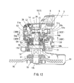
- FIGS. 12 to 17 illustrate an impact absorbing mechanism 50 according to a fourth embodiment.
- the impact absorbing mechanism 50 according to the fourth embodiment is configured to further improve durability of the impact absorbing mechanism 20 of the first embodiment. Members similar to those of the first embodiment will be given the same reference numerals and the description thereof will be omitted.
- steel balls 53 serving as a diameter-expanding-direction displacement member indirectly engage with the first inclined surface 13d of the driven shaft 13 via intermediate rollers 52, and in this respect, this embodiment is different from the first embodiment in which the steel balls 21 directly engage with the first inclined surfaces 13a of the driven shaft 13.
- the driven gear 51 meshing with the drive gear 6 is relatively rotatably supported on the driven shaft 13.
- the movement of the driven gear 51 in the axial direction is restricted as it is held between the thrust washer 27, which is fixed onto the driven shaft 13 by the nut 26, and the receiving flange 56 that is restricted in its movement in the axial direction by the bearing 15.
- the upper portion of the driven shaft 13 provided with the first inclined surfaces 13d is inserted into a support hole 51c of a driven gear 51. As shown in FIG.
- roller holding grooves 51a are provided along the radiating direction at the tri-sectional positions of the support hole 51c in the circumferential direction.
- One intermediate roller 52 is held inside each roller holding groove 51a.
- Each intermediate roller 52 is maintained in a posture in which its axis is positioned so as to be parallel to the axis of the driven shaft 13. Further, each intermediate roller 52 is positioned between the thrust washer 27 and an upper surface of a cylindrical shaft portion 56a of the receiving flange portion 56, so that the displacement in the axial direction is restricted.
- the intermediate rollers 52 respectively slidably contact with the respective first inclined surface 13d of the driven shaft 13 in a line-contact relationship.
- each intermediate roller 52 When the relative rotation between the driven gear 51 and the driven shaft 13 occurs, each intermediate roller 52 is pressed against the first inclined surface 13d and moves in parallel in a direction outward with respect to the radial direction of the spindle (the radiating direction). Each intermediate roller 52 moves in parallel in the radial direction within a movable range inside the roller holding groove 51a.
- steel ball holding grooves 51b are provided along the radiating direction at the tri-sectional positions of the support hole 51c in the circumferential direction.
- the positions of three steel ball holding grooves 51b in the circumferential direction correspond to the positions of the roller holding grooves 51a disposed on the upper surface side. For this reason, the upper portion of each intermediate roller 52 is positioned in the roller holding groove 51a, and the lower portion thereof is positioned inside the steel ball holding groove 51b.
- each intermediate roller 52 moves in parallel outward in the radiating direction while slidably contacting with the first inclined surface 13d, so that each steel ball 53 is pressed in the same direction by the intermediate roller 52.
- Each steel ball 53 protrudes outward from the lower surface (the steel ball holding groove 51b) of the driven gear 51 and is in contact with a second inclined surface 54a of an axial displacement member 54.
- the axial displacement member 54 is supported so as to be displaceable in the axial direction via a cylindrical tubular shaft portion 56a of a receiving flange 56.
- an axial elastic member 55 is interposed around the cylindrical tubular shaft portion 56a of the receiving flange 56.
- the axial elastic member 55 is held between the axial displacement member 54 and the flange portion 56b of the receiving flange 56.
- each steel ball 53 is relatively displaced in a direction of moving upward along the second inclined surface 54a of the axial displacement member 54, so that the axial displacement member 54 is displaced (downward) in a direction away from the lower surface of the driven gear 51 while pressing and compressing the axial elastic member 55 (against the elastic force).
- each steel ball 53 is positioned at the lowest position of the second inclined surface 54a (inward in the radiating direction), and accordingly, the inclination angle of the second inclined surface 54a or the diameter of each steel ball 53, etc. is appropriately set so that the axial displacement member 54 is elastically pressed against the lower surface of the driven gear 51 by the biasing force of the axial elastic member 55.
- the lock button 25 is pressed so that its front end portion 25a is fitted into any one of three stopper holes 51e, and hence the driven gear 51 and the driven shaft 13 can be conveniently locked during replacement of the whetsone or the like.
- each intermediate roller 52 is pressed outward in the radiating direction by the action of inclination of the first inclined surfaces 13d, so that each steel ball 53 is displaced in the same direction inside the steel ball holding groove 51b. Since each steel ball 53 is pressed outward in the radiating direction inside the steel ball holding groove 51b, the axial elastic member 55 is deformed in a direction in which it is pressed and compressed, thereby absorbing impact generated when the power is transmitted or interrupted according to starting or stopping of the electric motor 4.
- the intermediate rollers 52 are pressed against the first inclined surface 13d of the driven shaft 13 in a line-contact relationship therewith, and therefore, it is possible to reduce concentration of stress generated on the first inclined surfaces 13d so as to reduce its abrasion and to eventually improve the durability of the impact absorbing mechanism 50 in comparison with the configuration of the first embodiment in which the steel balls 21 to 21 are pressed in a direct point-contact relationship with the groove portions 13a that serve as the first inclined surface and have a V-shaped cross-section.
- the axial elastic member 55 performs various functions in addition to the impact absorbing function at the time of starting or stopping the electric motor. As shown in FIG.
- each steel ball 53 in the power interrupted state, each steel ball 53 is disposed at the lowest position of the second inclined surface 54a, and therefore, the axial displacement member 54 is elastically pressed against the lower surface of the driven gear 51 by the biasing force of the axial elastic member 55, whereby it is possible to prevent so-called lowering of the driven gear 51 (a phenomenon in which the upper surface moves away from the thrust washer 27 to cause shallow meshing of the drive gear 6), so that a secure meshing state of the drive gear 6 is maintained, and hence impact generated when starting the electric motor 4 is reduced.
- the fourth embodiment it is possible to change the displacement amount of the steel balls 533 and the displacement amount of the axial displacement member 54 by increasing the number of flat chamfered portions serving as the first inclined surface, changing the distance from the axis of the first inclined surface, or changing the inclination angle of the second inclined surface 54a of the axial displacement member 54, and accordingly, it is possible to obtain a sufficient impact absorbing function without an accompanying increase in the diameter of the driven gear 51.
- the fourth embodiment also may be modified into various forms.
- a configuration is exemplified in which three first inclined surfaces 13d are provided at the peripheral surface of the driven shaft 13, four first inclined surfaces or six first inclined surfaces may be provided.
- the combination of one intermediate roller 52 and one steel ball 53 may be disposed at four positions or six portions other than the configuration in which the combination is disposed at three positions in the circumferential direction as exemplified.
- a chamfered flat surface at the periphery of the driven shaft 13 has been exemplified as the first inclined surface 13d
- the V-shaped groove portion may be formed as the first inclined surface as in the first embodiment.
- the upper portion of the cylindrical tubular shaft portion 56a of the receiving flange 56 may have a shape cut to be shortened as shown in the drawing.
- the shape of the thrust washer 27 may be also changed.
- the lower surface of the thrust washer 27 shown in FIG. 18 is provided with a boss portion 27a.
- the boss portion 27a By inserting the boss portion 27a into the support hole 51c of the driven gear 51 and inserting the driven shaft 13 into the inner peripheral side of the boss portion 27a, the external force applied to the driven shaft 13 in the inclining direction of the driven gear 51 may be received by the thrust washer 27, so that the operation of the impact absorbing mechanism 50 can be made stable.
- the above-described embodiments may be further modified into various forms.
- the axial elastic members 23, 43, and 55 are formed of elastics
- other members such as compressive coil springs or disc springs may be used.
- gear trains for speed reduction of the disk grinder 1 have been exemplified as gear trains
- the present invention can be applied to impact absorbing mechanisms of gear trains of the other electric tools, such as a screw tightening machine, an electric drill for forming holes, or a cutting machine such as a circular table saw may be possible.
- the invention is not limited to electric tools but may also be applied to impact absorbing mechanisms of gear trains of various machines and instruments.
Landscapes
- Engineering & Computer Science (AREA)
- Mechanical Engineering (AREA)
- Gear Transmission (AREA)
- Portable Power Tools In General (AREA)
- Finish Polishing, Edge Sharpening, And Grinding By Specific Grinding Devices (AREA)
Abstract
Description
- The present invention relates to an impact absorbing mechanism of a gear train that reduces the rotational power of an electric motor and transmits the rotational power to a spindle in, for example, an electric tool such as a disk grinder.
- For example, a disk grinder includes a speed reduction gear train provided in a front portion of a body housing having an electric motor disposed therein. Rotational power of the electric motor is output to a spindle through a gear train through a meshing interaction between a driving-side bevel gear (a pinion gear) mounted to an output shaft and a driven-side bevel gear (a driven gear). For this reason, in general, the output shaft of the electric motor and the spindle are arranged such that their axes intersect each other. A threaded shaft portion is provided at the front end portion of the spindle. A whetstone may be mounted to the spindle by attaching the whetstone to the threaded shaft portion and fastening a fixing nut. When the fixing nut is loosened, the whetstone may be removed from the spindle for the purpose of replacement or the like.
When the electric motor is started or in particular when the electric motor with a brake is stopped, it is likely that impact or abnormal sound may be generated upon meshing of the gear train. Further, it is likely that the fixing nut fixing the whetstone to the spindle may be loosened due to the inertia torque of the whetstone generated when the brake is operated. For this reason, efforts have been made for reducing the impact, the inertia torque, or the like (hereinafter, simply referred to as impact). Hitherto, for example, in the following patent literature, a technique relating to an impact absorbing mechanism of a gear train in a disk grinder is disclosed. According to the impact absorbing mechanism of this related art, impact produced when starting and stopping an electric motor is reduced by supporting a driven gear and a spindle supporting the driven gear so as to be relatively rotatable with an allowance therebetween within a predetermined angle range and by interposing a plurality of (for example, four) elastic members between both components for setting an impact absorbing region in the rotational direction. -
- [Patent Document 1]
JP-A- 2007-275999 - In this way, with the impact absorbing mechanism of the related art, the impact absorbing region is set in the relative rotational direction between the driven gear and the spindle, and therefore, a plurality of elastic members are interposed between the driven gear and the spindle. As a result, each elastic member becomes a small component, which causes problems of degradation in the assembly performance of the driven gear with the spindle and eventually in the assembly performance of the disk grinder and also degradation in the durability of the same.
The present invention has been made in view of the above-described problems of the related art, and it is an object of the invention to reduce impact generated when starting and stopping an electric motor, while improving the assembling performance and durability over the related art. - This object may be achieved by the following inventions.
According to a first invention, there is provided an impact absorbing mechanism of a gear train that transmits rotational power of a driving shaft to a driven shaft, wherein the gear train includes a drive gear on the side of the driving shaft and a driven gear on the side of the driven shaft, which mesh with each other, wherein, in a rotational power transmission path between the driven gear and the driven shaft, there is provided a radial displacement member that is supported by the driven gear so as to be displaceable in a radial direction, an axial displacement member that is displaced in an axial direction by the displacement of the radial displacement member in a diameter expanding direction, and an axial elastic member that performs an impact absorbing action with respect to the displacement of the axial displacement member in the axial direction, and wherein the axial displacement member is displaced in the axial direction by the rotation of the driven gear relative to the driven shaft, so that impact generated upon meshing between the drive gear and the driven gear is absorbed.
With the first invention, when the drive gear and the driven gear mesh with each other to generate rotational power, the driven gear rotates relative to the driven shaft, and hence the radial displacement member is displaced in the diameter expanding direction so that the axial displacement member is displaced in the axial direction. The axial displacement member is displaced in the axial direction against the biasing force of the axial elastic member, whereby impact generated by meshing between the drive gear and the driven gear is absorbed. In this way, the rotation of the driven gear relative to the driven shaft is converted into the displacement of the axial displacement member in the axial direction via the radial displacement member, so that impact generated by the meshing operation is absorbed by using a single axial elastic member; accordingly, it is possible to eliminate a configuration in which a plurality of elastic members (rotational direction elastic members) are interposed between the driven gear and the spindle for directly absorbing impact in the rotational direction as in the related art, and hence it is possible to improve the assembling performance and the durability of the gear train.
The axial elastic member for absorbing the impact of the axial displacement member in the axial direction is only necessary to be interposed at the axial end surface of the axial displacement member without the need of interposing it between the driven gear and the driven shaft as in the rotational direction elastic member of the related art, and therefore, for example, an annular (ring-shaped) or C-shaped elastic member along the periphery of the driven shaft may be used, and hence a sufficient impact absorbing function may be given by using a single elastic member that is larger than in the related art.
Further, in the case of the configuration of the related art, it is necessary to interpose a plurality of impact absorbing members in the inner peripheral hole of the driven gear in order to obtain a sufficient impact absorbing function, and therefore, the diameter of the driven gear is increased, leading to limitation in terms of the setting of the gear ratio with respect to the drive gear. In contrast, with the impact absorbing mechanism according to the first invention, it is possible to appropriately set the displacement amount of the diameter-expanding-direction displacement member and the displacement amount of the axial displacement member by the inclination angles of the first inclined surface and the second inclined surface. Accordingly, since the elastic force (spring constant) of the axial elastic member may be set so as to obtain a sufficient impact absorbing function without causing an increase in the diameter of the driven gear as in the related art, it is possible to improve a degree of freedom in the setting of the gear ratio of the driven gear with respect to the drive gear. - According to a second invention, in the impact absorbing mechanism according to the first invention, the radial displacement member is engaged with a first inclined surface provided on the driven shaft and a second inclined surface provided on the axial displacement member, so that the radial displacement member is displaced in the radial direction by the displacement of the radial displacement member about the axis relative to the first inclined surface in association with rotation of the driven gear relative to the driven shaft, and the axial displacement member is displaced in the axial direction by the radial displacement of the radial displacement member relative to the second inclined surface in association with the radial displacement.
With the second invention, in addition to the operations and effects of the first invention, it is particularly possible to convert the relative rotation of the driven gear and the driven shaft into the displacement of the axial displacement member in the axial direction, for example, by providing a groove portion with a V-shaped cross-section along the axial direction as the first inclined surface on the driven shaft, providing the second inclined surface that has, for example, a tapered shape at the open end of the inner periphery of the axial displacement member, and configuring such that the radial displacement member is held between both inclined surfaces.
According to a third invention, the impact absorbing mechanism according to the second invention is provided with a steel ball supported by the driven gear so as to be displaceable in the radial direction is provided as the radial displacement member, and the steel ball is held between the first inclined surface and the second inclined surface, so that the steel ball is displaced in the radial direction by the rotation of the driven gear relative to the driven shaft and the axial displacement member is displaced in the axial direction.
With the third invention, one steel ball or a plurality of steel balls may be provided as the radial displacement member, with the steel ball(s) interposed between the first inclined surface and the second inclined surface, and therefore, making it possible to assuredly displace the axial displacement member in the axial direction to assuredly perform the impact absorbing function with a simple configuration. - According to a fourth invention, there is provided the impact absorbing mechanism according to the third invention, wherein an intermediate roller is interposed between the steel ball and the first inclined surface so as to engage with the first inclined surface in a line-contact relationship therewith, so that the steel ball indirectly engages with the first inclined surface, and the steel ball is displaced in the radial direction by the radial displacement of the intermediate roller, so that the axial displacement member is displaced in the axial direction.
With the fourth invention, the steel ball indirectly engages with the first inclined surface via the intermediate roller so as to be held between the first inclined surface and the second inclined surface. The steel ball does not directly engage the first inclined surface, but instead, the intermediate roller engages with the first inclined surface in a line-contact relationship therewith, and therefore, stress generated at the first inclined surface is distributed as compared to the configuration in which the steel ball engages in a point-contact relationship. Since the concentration of stress generated at the first inclined surface is reduced, abrasion of the first inclined surface is reduced, and hence the durability of the impact absorbing mechanism may be improved.
According to a fifth invention, there is provided the impact absorbing mechanism according to any one of the first to fourth inventions, wherein the driven gear is biased in a direction, in which the drive gear meshes deeper with the driven gear, by a biasing force of the axial elastic member applied via the axial displacement member.
With the fifth invention, since the engaging condition of the drive gear with the driven gear is always maintained at an appropriate depth, and therefore, also in this respect, it is possible to reduce the impact generated by meshing of the gears when the electric motor is started.
According to a sixth invention, there is provided the impact absorbing mechanism according to any one of the first to fifth inventions, wherein a single elastic member having an annular shape is used as the axial elastic member.
With the sixth invention, since it is only necessary to affix one annular elastic member to the gear train, it is possible to improve the assembling performance and the durability compared to the related art.
According to a seventh invention, there is provided a disk grinder comprising the impact absorbing mechanism according to any one of the first to sixth inventions, comprising the drive gear rotated by an electric motor, a bevel gear that serves as the driven gear with which the drive gear meshes, and a spindle serving as the driven shaft and supporting the bevel gear, wherein a circular whetstone is provided on the spindle, a steel ball serving as the radial displacement member is interposed in the rotational power transmission path between the bevel gear and the spindle, so that the axial elastic member is operated with respect to the axial displacement of the axial displacement member associated with the displacement of the steel ball in the diameter expanding direction, thereby absorbing impact generated upon meshing between the drive gear and the bevel gear when starting or stopping the electric motor.
With the seventh invention, it is possible to improve the assembling performance and the durability of the impact absorbing mechanism of the gear train. - According to an eighth invention, there is provided an impact absorbing mechanism of a gear train that transmits rotational power of a driving shaft to a driven shaft, wherein the gear train includes a drive gear on the side of the driving shaft and a driven gear on the side of the driven-shaft, which mesh with each other, wherein, in a rotational power transmission path between the driven gear and the driven shaft, there is provided a radial displacement member that is supported by the driven gear so as to be displaceable in a radial direction, and a radial elastic member that performs an impact absorbing action with respect to the displacement of the radial displacement member in the diameter expanding direction, and wherein the radial displacement member is displaced in the diameter expanding direction by the rotation of the driven gear relative to the driven shaft, so that impact generated upon meshing between the drive gear and the driven gear is absorbed.
With the eighth invention, as the drive gear and the driven gear mesh with each other, a relative rotation is generated between the driven gear and the driven shaft, and hence the radial displacement member is displaced in the diameter expanding direction. Then, the radial elastic member is operated with respect to the displacement so as to absorb impact. In this way, since the impact is absorbed by the conversion of the rotation of the driven gear relative to the driven shaft into the displacement of the radial displacement member in the diameter expanding direction, it is possible to eliminate a construction in which a plurality of elastic members (rotation-direction elastic members) that directly absorb impact in the rotation direction are interposed between the driven gear and the spindle as in the related art, and hence it is possible to improve the assembling performance and the durability of the gear train.
The radial elastic member that absorbs impact of the radial displacement member in the diameter expanding direction is not required to be placed between the driven gear and the driven shaft as in the rotation-direction elastic member of the related art, but instead, it is only necessary that the radial elastic member is placed on the outer peripheral side (the diameter expanding side) of the radial displacement member, and therefore, it is possible to use, for example, an annular (ring-shaped) or C-shaped elastic member along the outer peripheral side of the boss portion of the driven gear which holds the radial displacement member, and therefore, a sufficient impact absorbing ability may be produced using a single elastic member which is larger than in the related art.
According to a ninth invention, there is provided the impact absorbing mechanism according to the eighth invention, wherein an inclined surface is provided on the side of the driven gear or the side of the driven shaft, and the radial displacement member is engaged with the inclined surface so that the radial displacement member is displaced in the diameter expanding direction by the rotation of the driven gear relative to the driven shaft.
With the ninth invention, in addition to the operations and effects of the eighth invention, it is particularly possible to convert the relative rotation of the driven gear and the driven shaft into the displacement of the radial displacement member in the diameter expanding direction, for example, by providing a groove portion along the axial direction as the first inclined surface on the driven shaft and engaging the radial displacement member with the inclined surface of the groove portion.
According to a tenth invention, there is provided the impact absorbing mechanism according to the ninth invention, wherein a roller serving as the radial displacement member is engaged with the inclined surface on the side of the driven shaft, and a C-shaped radial elastic member is displaced in the diameter expanding direction with respect to the displacement of the roller in the diameter expanding direction so as to create an impact absorbing action.
With the tenth invention, one steel ball or a plurality of steel balls may be provided as the radial displacement member, and the steel ball(s) may be fitted into the groove portion (the inclined surface) of the driven shaft, and the C-shaped radial elastic member may be disposed at the periphery of the steel ball(s), and therefore, it is possible to assuredly displace the radial displacement member in the diameter expanding direction to assuredly perform the impact absorbing function using a simple configuration.
According to an eleventh invention, there is provided a disk grinder with the impact absorbing mechanism according to any one of the eighth to tenth inventions, comprising the drive gear rotated by an electric motor, a bevel gear that serves as the driven gear with which the drive gear meshes, and a spindle serving as the driven shaft and supporting the bevel gear, wherein a circular whetstone is provided on the spindle, a roller serving as the radial displacement member is interposed in the rotational power transmission path between the bevel gear and the spindle, so that the radial elastic member is operated with respect to the displacement of the roller in the diameter expanding direction, thereby absorbing impact generated upon meshing between the drive gear and the bevel gear when starting or stopping the electric motor.
With the eleventh invention, it is possible to improve the assembling performance and the durability of the impact absorbing mechanism of the gear train. -
-
FIG. 1 is a side view of an entire disk grinder provided with an impact absorbing mechanism according to a first embodiment of the present invention. In this figure, a front portion of a tool body and a gear head portion having a gear train disposed therein are shown in a vertical sectional view. In addition, this figure shows a state where an electric motor is stopped. -
FIG. 2 is sectional view taken along line (II)-(II) inFIG. 1 and showing a horizontal sectional view of the gear train. -
FIG. 3 is a vertical sectional view of the gear head portion with the impact absorbing mechanism of the first embodiment. This figure shows a state where the electric motor is started. -
FIG. 4 is a sectional view taken along line (IV)-(IV) inFIG. 3 and showing a horizontal sectional view of the gear train. -
FIG. 5 is a vertical sectional view of a gear head portion with an impact absorbing mechanism according to a second embodiment of the present invention. This figure shows a state where the electric motor is stopped. -
FIG. 6 is a sectional view taken along line (VI)-(VI) inFIG. 5 and showing a horizontal sectional view of a gear train. -
FIG. 7 is a vertical sectional view of the gear head portion with the impact absorbing mechanism according to the second embodiment. This figure shows a state where the electric motor is started. -
FIG. 8 is a sectional view taken along line (VIII)-(VIII) inFIG. 7 and showing a horizontal sectional view of the gear train. -
FIG. 9 is a vertical sectional view of a gear head portion with an impact absorbing mechanism according to a third embodiment of the present invention. This figure shows a state where an electric motor is stopped. -
FIG. 10 is a sectional view taken along line (X)-(X) inFIG. 9 showing a horizontal sectional view of a gear train. -
FIG. 11 is a vertical sectional view of the gear head portion with the impact absorbing mechanism according to the third embodiment. This figure shows the state where the electric motor is started. -
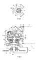
FIG. 12 is a vertical sectional view of a gear head portion with an impact absorbing mechanism according to a fourth embodiment. This figure shows a state where an electric motor is stopped. -
FIG. 13 is a view taken along line (XIII)-(XIII) inFIG. 12 showing a plan view of a driven gear. -
FIG. 14 is a view taken along line (XIV)-(XIV) inFIG. 12 showing a bottom view of the driven gear. -
FIG. 15 is a vertical sectional view of the gear head portion with the impact absorbing mechanism according to the fourth embodiment. This figure shows a state where the electric motor is started. -
FIG. 16 is a sectional view taken along line (XVI)-(XVI) inFIG. 15 showing a plan view of the driven gear. -
FIG. 17 is a view taken along line (XVII)-(XVII) inFIG. 15 showing a bottom view of the driven gear. -
FIG. 18 is vertical sectional view of a gear head portion with modification to the impact absorbing mechanism of the fourth embodiment. This figure shows a state where the electric motor is started. - Next, embodiments of the present invention will be described by referring to
FIGS. 1 to 18 .FIG. 1 illustrates adisk grinder 1 with an impact absorbing mechanism according to a first embodiment. Thedisk grinder 1 includes atool body portion 2 and agear head portion 10. Thetool body portion 2 has a configuration in which anelectric motor 4 serving as a driving source is disposed within a substantially cylindricaltubular body housing 3. The thickness of thebody housing 3 is set to be easily gripped by one hand of a user. Aswitch lever 5 which is operated by a finger tip of a user is disposed on the upper portion of the body housing. When theswitch lever 5 is slid to the front side (the left side in the drawing), theelectric motor 4 is started. When theswitch lever 5 is slid to the rear side (the right side in the drawing), theelectric motor 4 is stopped.
A front portion of anoutput shaft 4a of theelectric motor 4 is rotatably supported by abearing 7 which is mounted to the front end portion of thebody housing 3. Further, amotor cooling fan 8 is mounted to theoutput shaft 4a. By the coolingfan 8 and abaffle plate 9 disposed therearound, external air is introduced from the rear portion of thebody housing 3, and the introduced external air flows forward inside thebody housing 3, thereby efficiently cooling theelectric motor 4.
Thegear head portion 10 is coupled to the front portion of thetool body portion 2. Thegear head portion 10 includes agear housing 11. Thegear housing 11 is coupled to the front portion of thebody housing 3 of thetool body portion 2. Theoutput shaft 4a of theelectric motor 4 protrudes into thegear housing 11. Adrive gear 6 is mounted to theoutput shaft 4a of theelectric motor 4. A bevel gear (a bevel gear wheel) is used for thedrive gear 6. - The
drive gear 6 meshes with a drivengear 12. A bevel gear (a bevel gear wheel) is also used as the drivengear 12,. Thedrive gear 6 and the drivengear 12 constitute the term gear train used in the claims.
The drivengear 12 is supported by a drivenshaft 13. The upper portion of the drivenshaft 13 is rotatably supported by abearing 14, and the lower portion thereof is rotatably supported by abearing 15. The drivenshaft 13 is supported in such a direction that its axis is substantially perpendicular to the axis of theoutput shaft 4a of theelectric motor 4.
The lower portion of the drivenshaft 13 protrudes downward from the lower portion of thegear housing 11. Acircular whetstone 16 is attached to the protruding portion. A threadedshaft portion 13b is formed on the lower end portion of the drivenshaft 13. Thewhetstone 16 is fixed to the drivenshaft 13 by firmly tightening a fixingnut 18 against the threadedshaft portion 13b with thewhetstone 16 interposed between the fixing nut and a fixedflange 17.
Awhetstone cover 19 is attached to the lower portion of thegear housing 11. The whetstone cover 19 covers the rear half circumference range of thewhetstone 16, thereby preventing ground powder from scattering backwards (toward the user). - The driven
gear 12 is supported so as to be relatively rotatable about the axis. However, the drivengear 12 is supported by athrust washer 27, which is fixed onto the drivenshaft 13 by anut 26, so as not to be movable in the axial direction. Animpact absorbing mechanism 20 according to the first embodiment is interposed on a rotational power transmission path between the drivengear 12 and the drivenshaft 13. Theimpact absorbing mechanism 20 of the first embodiment includes threesteel balls 21 that are held by the drivengear 12, anaxial displacement member 22 displaceable in the axial direction (in the vertical direction inFIG. 1 ) of the drivenshaft 13, and an axialelastic member 23.
Aboss portion 12a is integrally formed with the lower surface of the drivengear 12. A drivenshaft 13 is inserted into the inner periphery of theboss portion 12a so as to be relatively rotatable. Holdingholes 12b are provided at tri-sectional positions around theboss portion 12a so as to penetrate in the radial direction. Onesteel ball 21 is held inside each holdinghole 12b so as to be displaceable in the radial direction. The thickness of theboss portion 12a is appropriately set, so that thesteel balls 21 protrude from both open end portions of the respective holdingholes 12b.
In the drivenshaft 13, threegroove portions 13a having a V-shaped cross-section and elongated in the axial direction are formed at the tri-sectional positions about the axis. Onesteel ball 21 protruding from the inner periphery of theboss portion 12a is fitted into eachgroove portion 13a. For this reason, as shown inFIG. 4 , when the drivengear 12 rotates relative to the drivenshaft 13, eachsteel ball 21 is displaced in the diameter expanding direction upward on the inclined surface of thegroove portion 13a. Accordingly, eachsteel ball 21 corresponds to an example of a diameter-expanding-direction displacement member defined in the claims, and the inclined surface of eachgroove portion 13a corresponds to a first inclined surface.
Theaxial displacement member 22 is disposed on the outer peripheral side of theboss portion 12a of the drivengear 12. Theaxial displacement member 22 is formed in a cylindrical tubular shape having aflange portion 22a at its upper portion, and theboss portion 12a of the drivengear 12 is inserted into its inner periphery so as to be relatively rotatable about the axis and to be relatively displaceable in the axial direction. Atapered surface 22b is formed at the upper open end portion on the inner peripheral side of theaxial displacement member 22. Threesteel balls 21 protruding toward the outer peripheral side of theboss portion 12a are in contact with thetapered surface 22b. Thetapered surface 22b corresponds to a second inclined surface defined in the claims. - The axial
elastic member 23 is disposed on the lower surface side of theflange portion 22a on the outer peripheral side of theaxial displacement member 22. The axialelastic member 23 has an annular shape having a rectangular cross-section as shown in the drawings, and an elastic with an appropriate elasticity in the axial direction is used. A receivingflange 24 is disposed on the lower side of theaxial displacement member 22. The receivingflange 24 is supported by the drivenshaft 13 such that it is interposed between theboss portion 12a of the drivengear 12 and the inner race of thebearing 15 so as not to be displaced in the axial direction. The axialelastic member 23 is interposed between the receivingflange 24 and theflange portion 22a of theaxial displacement member 22. Theaxial displacement member 22 is displaceable downward in the axial direction while theaxial displacement member 23 is compressed downward (against its elastic force) when pressed upon.
Alock button 25 for locking the idle rotation of the drivengear 12 is disposed in the front portion on the upper surface side of thegear head portion 10. When thelock button 25 is pressed by a finger tip, afront end portion 25a protruding into thegear housing 11 is fitted into any one of threestopper holes 12d provided in the upper surface of the drivengear 12, thereby locking the idle rotation of the drivengear 12. For this reason, when thelock button 25 is pushed at the time of removing or mounting thewhetstone 16 from or to the drivenshaft 13, the idle rotation of not only the drivengear 12 but also the drivenshaft 13 is locked, so that the fixingnut 18 can be easily loosened or tightened, leading to facilitate the replacement and the maintenance works of thewhetstone 16. - With the
impact absorbing mechanism 20 of the first embodiment configured as described above, impact generated due to meshing between thedrive gear 6 and the drivengear 12 as theelectric motor 4 is started or stopped is absorbed by the displacement of the axialelastic member 23 in the axial direction. When thedrive gear 6 meshes with the drivengear 12 to transmit rotational power thereto as theelectric motor 4 is started, the drivengear 12 rotates slightly relative to the drivenshaft 13. As the drivengear 12 rotates relative to the drivenshaft 13, eachsteel ball 21 is displaced within thegroove portion 13a in the width direction relative thereto. Accordingly, eachsteel ball 21 is displaced in such a direction that the amount protruding toward the outer peripheral side of theboss portion 12a increases such that thesteel ball 21 is removed from the inside of thegroove portion 13a (the diameter expanding direction).
As the protruding amount of eachsteel ball 21 toward the outer peripheral side of theboss portion 12a increases, theaxial displacement member 22 is displaced downward by the interaction between eachsteel ball 21 and thetapered surface 22b of theaxial displacement member 22. As described previously, theaxial displacement member 22 is displaced downward against the elastic force of the axialelastic member 23. Thus, the drivengear 12 rotates relative to the drivenshaft 13 while theaxial displacement member 22 is displaced in the axial direction against the elastic force of the axialelastic member 23, whereby impact generated when thedrive gear 6 and the drivengear 12 mesh with each other is absorbed.
In this way, theimpact absorbing mechanism 20 of the first embodiment is configured to absorb impact by converting the rotation of the drivengear 12 relative to the drivenshaft 13 into the displacement of theaxial displacement member 22 in the axial direction, and therefore, there is no need to interpose a small elastic component between the driven gear and the driven shaft in order to apply an elastic force in the relative rotation direction as in the related art. Accordingly, it is possible to improve the ease of manufacture and the durability of theimpact absorbing mechanism 20 and of thedisk grinder 1 overall.
Further, with theimpact absorbing mechanism 20 of the first embodiment, the displacement amount of thesteel balls 21 and the displacement amount of theaxial displacement member 22 may be appropriately set by arbitrarily setting the inclination angle of thegroove portion 13a as the first inclined surface or the inclination angle of the taperedsurface 22b (the first inclined surface) as the second inclined surface, whereby it is possible to appropriately set the displacement amount of the axialelastic member 23. For this reason, it is possible to easily obtain a sufficient cushion function by appropriately setting the displacement amount of the axialelastic member 23 without increasing the diameter of the driven gear as in the related art.
Furthermore, since the biasing force of the axialelastic member 23 is applied in a direction in which the upper drivengear 12 deeply meshes with thedrive gear 6 through the secondinclined surface 22b and thesteel balls 21, the meshing sate of thedrive gear 6 with the drivengear 12 can be properly maintained. The impact generated at the time of starting theelectric motor 4 may be reduced also in this respect.
The first embodiment may be modified in various forms. For example, although thegroove portions 13a having a V-shaped cross-section are exemplified as the first inclined surface, this may be replaced with a construction to provide groove portions having a semi-circular cross-section. -
FIGS. 5 to 8 illustrate animpact absorbing mechanism 30 according to a second embodiment. Members similar to those of the first embodiment will be given the same reference numerals as those of the first embodiment, and the description thereof will be omitted. In theimpact absorbing mechanism 20 of the first embodiment, the impact is absorbed due to displacement of theaxial displacement member 22 in the axial direction as eachsteel ball 21 serving as the diameter-expanding-direction displacement member is displaced in the diameter expanding direction. However, in a second embodiment to be described later, it is configured such that impact is directly absorbed with respect to movement in each direction of eachroller 31 serving as a diameter-expanding-direction displacement member.
Similar to the first embodiment, at the tri-sectional positions on the axis, the drivenshaft 13 is provided with thegroove portions 13a elongated in the axial direction and having a V-shaped cross-section. Theroller 31 is fitted into eachgroove portion 13a. Eachroller 31 is held by the holdinghole 12b provided in theboss portion 12a of the drivengear 12 so as to be displaceable in the diameter expanding direction. Eachroller 31 is pressed against the diameter-expanding-directionelastic member 32 as it is displaced in the diameter expanding direction. As shown inFIG. 6 , the diameter-expanding-directionelastic member 32 is a C-shaped metal spring and has a biasing force for displacing eachroller 31 in a diameter contracting direction (a direction pressing into thegroove portion 13a).
An engagementconvex portion 12c protruding towards the outer peripheral side of theboss portion 12a of the drivengear 12 enters between opposite end portions of the diameter-expanding-directionelastic member 32. Accordingly, the rotation of the diameter-expanding-directionelastic member 32 is prevented, so that a gap between opposite end portions of the diameter-expanding-directionelastic member 32 does not open up at the outer peripheral side of eachroller 31. For this reason, all of therollers 31 are normally pressed against the inner peripheral surface of the diameter-expanding-directionelastic member 32.
A holdingsleeve 33 is supported on the drivenshaft 13 on the lower side of the drivengear 12 so as to be coaxial with the drivengear 12. The holdingsleeve 33 is supported by the drivenshaft 13 while the displacement in the axial direction is restricted as in the case of the receivingflange 24 of the first embodiment. A holding cylindricaltubular portion 33a which protrudes with an L-shaped cross-section is integrally formed with the outer periphery of the holdingsleeve 33. The diameter-expanding-directionelastic member 32 is accommodated in a cylindrical tubular space between the holding cylindricaltubular portion 33a and theboss portion 12a of the drivengear 12.
As shown inFIGS. 5 and6 , while theelectric motor 4 is inactive and rotational power is not generated, eachroller 31 is pressed into the deepest position inside thegroove portion 13a by the biasing force of the diameter-expanding-directionelastic member 32. As a result, the diameter-expanding-directionelastic member 32 is displaced in the diameter contracting direction so as to substantially closely contact theboss portion 12a of the drivengear 12, so that a gap is formed between the diameter-expanding-direction elastic member and the holding cylindricaltubular portion 33a. - According to the
impact absorbing mechanism 30 of the second embodiment with the above-described configuration, impact generated by meshing between thedrive gear 6 and the drivengear 12 when starting and stopping theelectric motor 4 is absorbed by the diameter-expanding-directionelastic member 32. When thedrive gear 6 meshes with the drivengear 12 to transmit rotational power there to due to the starting of theelectric motor 4, the drivengear 12 slightly rotates relative to the drivenshaft 13. As the drivengear 12 rotates relative to the drivenshaft 13, eachroller 31 is relatively displaced inside thegroove portion 13a in the width direction to ascend along the first inclined surface toward the shallower position as shown inFIGS. 7 and8 , and therefore, eachroller 31 is displaced in a direction of increasing the protruding amount toward the outer peripheral side of theboss portion 12a in a direction away from the inside of thegroove portion 13a (the diameter expanding direction).
As the amount of eachroller 31 protruding towards the outer peripheral side of theboss portion 12a increases, eachroller 31 is pressed against the inner peripheral surface of the diameter-expanding-directionelastic member 32. As a result, the diameter-expanding-directionelastic member 32 becomes elastically deformed in the diameter expanding direction against the biasing force, so that the impact generated upon meshing between thedrive gear 6 and the drivengear 12 is absorbed. For this reason, the displacement of eachroller 31 in the diameter expanding direction acts against the biasing force of the diameter-expanding-directionelastic member 32, so that the rotation of the drivengear 12 relative to the drivenshaft 13 acts against the biasing force of the diameter-expanding-directionelastic member 32.
FIGS. 7 and8 illustrate the state where the drivengear 12 has been rotated relative to the drivenshaft 13, so that eachroller 31 has been displaced to the shallower position of thegroove portion 13a (in the diameter expanding direction) and the diameter-expanding-directionelastic member 32 has been pressed and widened in the diameter expanding direction; and as a result, the diameter-expanding-directionelastic member 32 has been pressed and widened to a position where the diameter-expanding-directionelastic member 32 substantially closely contacts the inner peripheral surface of the holdingsleeve 33a, so that a gap is formed between the diameter-expanding-direction elastic member and theboss portion 12a.
Furthermore, in the second embodiment, a member corresponding to theaxial displacement member 22 of the first embodiment is omitted. Accordingly, an inclined surface corresponding to the second inclined surface (thetapered surface 22b) of the first embodiment is omitted.
In this way, in theimpact absorbing mechanism 30 of the second embodiment, impact is absorbed by converting the rotation of the drivengear 12 relative to the drivenshaft 13 into the elastic deformation of the diameter-expanding-directionelastic member 32 in the diameter expanding direction, and therefore, there is no need to place small elastic components between the driven gear and the driven shaft in order to create the elastic force in the relative rotation direction as in the related art. Accordingly, it is possible to improve the ease of manufacture and the durability of theimpact absorbing mechanism 30 and eventually those of thedisk grinder 1.
The second embodiment also may be modified into various forms. For example, as in the first embodiment, groove portions having a semi-circular cross-section may be used instead of thegroove portions 13a having a V-shaped cross-section and serving as the first inclined surface. - Next,
FIGS. 9 to 11 illustrate animpact absorbing mechanism 40 according to a third embodiment. In the third embodiment, thesteel balls 21 serving as the diameter-expanding-direction displacement member of the first embodiment are omitted and are replaced with a cam portion provided between a drivengear 41 and anaxial displacement member 42, so that, as the drivengear 41 rotates relative to the drivenshaft 13, impact is absorbed by displacing theaxial displacement member 42 in the axial direction by the action of the cam portion. Members and constructions similar to those of the first embodiment will be given the same reference numerals and the description will be omitted.
The drivengear 41 meshing with thedrive gear 6 is relatively rotatably supported on the drivenshaft 13. The lower end portion of a boss portion of the drivengear 41 is provided with camconvex portions 41 a protruding downward in a V-shape. Both camconvex portions 41a are disposed at the bisection positions about the axis.
Theaxial displacement member 42 is disposed on the lower side of the drivengear 41. Theaxial displacement member 42 is axially displaceably supported by the drivenshaft 13. The upper open end portion of the inner peripheral hole of theaxial displacement member 42 is provided with V-shaped camconcave portions 42b which correspond to the camconvex portions 41 a. Further, in the inner peripheral hole of theaxial displacement member 42, engagementconvex portions 42c having a rectangular cross-section are provided at the bisectional positions in the circumferential direction, which are opposed to each other. Both engagementconvex portions engagement groove portions 13c which are respectively provided in the drivenshaft 13, also have a rectangular cross-section and are elongated in the axial direction. For this reason, theaxial displacement member 42 is supported so as to be displaceable in the axial direction relative to the drivenshaft 13 while being non-rotatable about the axis.
Similar to the first embodiment, theaxial displacement member 42 is provided with aflange portion 42a. An axialelastic member 43 is interposed on the lower surface side of theflange portion 42a. On the lower side of theaxial displacement member 42, the receivingflange 24 is supported by the drivenshaft 13 as in the first embodiment. Similar to the first embodiment, the receivingflange 24 is supported by the drivenshaft 13 in the state that its displacement in the axial direction is restricted. Theaxial displacement member 42 is displaceable in the axial direction between the receivingflange 24 and the drivengear 41.
The axialelastic member 43 is interposed between the receivingflange 24 and theflange portion 42a of theaxial displacement member 42. As in the first embodiment, an annular elastic may be used for the axial elastic member. - In the
impact absorbing mechanism 40 of the third embodiment with the above-described configuration, impact generated by meshing between the drivengear 6 and the drivengear 41 when starting or stopping theelectric motor 4 is absorbed by the displacement of theaxial displacement member 42 in the axial direction. When thedrive gear 6 meshes with the drivengear 41 to transmit rotational power due to the starting of theelectric motor 4, the drivengear 41 slightly rotates relative to the drivenshaft 13. As the drivengear 41 rotates relative to the drivenshaft 13, the camconvex portions 41a on the side of the drivengear 41 are displaced about the axis relative to the camconcave portions 42b on the side of theaxial displacement member 42 that does not rotate relative to the drivenshaft 13. As a result, the camconvex portion 41 a is displaced to a shallower position of the camconcave portion 42b, so that theaxial displacement member 42 is displaced downward in the axial direction. Since the axialelastic member 43 is interposed between theflange portion 42a of theaxial displacement member 42 and the receivingflange 24, theaxial displacement member 42 is displaced downward while pressing and compressing the axial elastic member 43 (against the elastic force), whereby impact generated by meshing between thedrive gear 6 and the drivengear 12 is absorbed. In this way, as also occurs with the construction of theimpact absorbing mechanism 40 of the third embodiment, impact is absorbed by converting the rotation of the drivengear 41 relative to the drivenshaft 13 into the displacement of theaxial displacement member 42 in the axial direction, and therefore, there is no need to interpose small elastic components between the driven gear and the driven shaft for applying an elastic force in the relative rotation direction as in the related art. Accordingly, it is possible to improve the ease of manufacture and the durability of theimpact absorbing mechanism 40 and eventually of thedisk grinder 1.
Further, since the biasing force of the axialelastic member 43 is applied through theaxial displacement member 42 in an upward direction in which the drivengear 41 deeply meshes with thedrive gear 6, the meshing state of thedrive gear 6 with the drivengear 41 can be properly maintained. Impact generated when starting theelectric motor 4 may be reduced also in this respect. -
FIGS. 12 to 17 illustrate animpact absorbing mechanism 50 according to a fourth embodiment. Theimpact absorbing mechanism 50 according to the fourth embodiment is configured to further improve durability of theimpact absorbing mechanism 20 of the first embodiment. Members similar to those of the first embodiment will be given the same reference numerals and the description thereof will be omitted. In theimpact absorbing mechanism 50 of the fourth embodiment,steel balls 53 serving as a diameter-expanding-direction displacement member indirectly engage with the firstinclined surface 13d of the drivenshaft 13 viaintermediate rollers 52, and in this respect, this embodiment is different from the first embodiment in which thesteel balls 21 directly engage with the firstinclined surfaces 13a of the drivenshaft 13.
Similar to the first embodiment, the drivengear 51 meshing with thedrive gear 6 is relatively rotatably supported on the drivenshaft 13. However, the movement of the drivengear 51 in the axial direction is restricted as it is held between thethrust washer 27, which is fixed onto the drivenshaft 13 by thenut 26, and the receivingflange 56 that is restricted in its movement in the axial direction by thebearing 15.
On the upper portion of the drivenshaft 13, three firstinclined surfaces 13d are provided and are different from thegroove portions 13a of the first embodiment in that they are formed by being flatly chamfered at tri-sectional positions about the axis. The upper portion of the drivenshaft 13 provided with the firstinclined surfaces 13d is inserted into asupport hole 51c of a drivengear 51. As shown inFIG. 13 , on the upper surface side of the drivengear 51,roller holding grooves 51a are provided along the radiating direction at the tri-sectional positions of thesupport hole 51c in the circumferential direction. Oneintermediate roller 52 is held inside eachroller holding groove 51a. Eachintermediate roller 52 is maintained in a posture in which its axis is positioned so as to be parallel to the axis of the drivenshaft 13. Further, eachintermediate roller 52 is positioned between thethrust washer 27 and an upper surface of acylindrical shaft portion 56a of the receivingflange portion 56, so that the displacement in the axial direction is restricted.
Theintermediate rollers 52 respectively slidably contact with the respective firstinclined surface 13d of the drivenshaft 13 in a line-contact relationship. When the relative rotation between the drivengear 51 and the drivenshaft 13 occurs, eachintermediate roller 52 is pressed against the firstinclined surface 13d and moves in parallel in a direction outward with respect to the radial direction of the spindle (the radiating direction). Eachintermediate roller 52 moves in parallel in the radial direction within a movable range inside theroller holding groove 51a.
As shown inFIG. 14 , on the lower surface side of the drivengear 51, steelball holding grooves 51b are provided along the radiating direction at the tri-sectional positions of thesupport hole 51c in the circumferential direction. The positions of three steelball holding grooves 51b in the circumferential direction correspond to the positions of theroller holding grooves 51a disposed on the upper surface side. For this reason, the upper portion of eachintermediate roller 52 is positioned in theroller holding groove 51a, and the lower portion thereof is positioned inside the steelball holding groove 51b. - One
steel ball 53 is movably held inside each steelball holding groove 51b. When relative rotation is caused between the drivengear 51 and the drivenshaft 13, eachintermediate roller 52 moves in parallel outward in the radiating direction while slidably contacting with the firstinclined surface 13d, so that eachsteel ball 53 is pressed in the same direction by theintermediate roller 52.
Eachsteel ball 53 protrudes outward from the lower surface (the steelball holding groove 51b) of the drivengear 51 and is in contact with a secondinclined surface 54a of anaxial displacement member 54. Theaxial displacement member 54 is supported so as to be displaceable in the axial direction via a cylindricaltubular shaft portion 56a of a receivingflange 56. On a lower surface side of theaxial displacement member 54, an axialelastic member 55 is interposed around the cylindricaltubular shaft portion 56a of the receivingflange 56. The axialelastic member 55 is held between theaxial displacement member 54 and theflange portion 56b of the receivingflange 56.
As relative rotation occurs between the drivengear 51 and the drivenshaft 13 to press eachsteel ball 53 outward in the radiating direction by theintermediate roller 52, as described above, eachsteel ball 53 is relatively displaced in a direction of moving upward along the secondinclined surface 54a of theaxial displacement member 54, so that theaxial displacement member 54 is displaced (downward) in a direction away from the lower surface of the drivengear 51 while pressing and compressing the axial elastic member 55 (against the elastic force). For this reason, the rotation of the drivengear 51 relative to the drivenshaft 13 is performed against the elastic force of the axialelastic member 55 as in the first embodiment, so that impact generated upon transmitting a driving force between the drivengear 51 and the drivenshaft 13 is absorbed.
Further, as shown inFIG. 12 , in a state where a driving force is interrupted, eachsteel ball 53 is positioned at the lowest position of the secondinclined surface 54a (inward in the radiating direction), and accordingly, the inclination angle of the secondinclined surface 54a or the diameter of eachsteel ball 53, etc. is appropriately set so that theaxial displacement member 54 is elastically pressed against the lower surface of the drivengear 51 by the biasing force of the axialelastic member 55.
On the upper surface of the drivengear 51, threestopper holes 51e to 51e are provided at the tri-sectional positions in the circumferential direction. Similar to the above embodiments, thelock button 25 is pressed so that itsfront end portion 25a is fitted into any one of threestopper holes 51e, and hence the drivengear 51 and the drivenshaft 13 can be conveniently locked during replacement of the whetsone or the like. - Also with the
impact absorbing mechanism 50 of the fourth embodiment with the above-described configuration, as rotation occurs between the drivenshaft 13 and the drivengear 51 when starting or stopping the electric motor 4 (when transmitting or interrupting the driving force), eachintermediate roller 52 is pressed outward in the radiating direction by the action of inclination of the firstinclined surfaces 13d, so that eachsteel ball 53 is displaced in the same direction inside the steelball holding groove 51b. Since eachsteel ball 53 is pressed outward in the radiating direction inside the steelball holding groove 51b, the axialelastic member 55 is deformed in a direction in which it is pressed and compressed, thereby absorbing impact generated when the power is transmitted or interrupted according to starting or stopping of theelectric motor 4. Further, in the case of the fourth embodiment, since theintermediate rollers 52 are pressed against the firstinclined surface 13d of the drivenshaft 13 in a line-contact relationship therewith, and therefore, it is possible to reduce concentration of stress generated on the firstinclined surfaces 13d so as to reduce its abrasion and to eventually improve the durability of theimpact absorbing mechanism 50 in comparison with the configuration of the first embodiment in which thesteel balls 21 to 21 are pressed in a direct point-contact relationship with thegroove portions 13a that serve as the first inclined surface and have a V-shaped cross-section. Furthermore, the axialelastic member 55 performs various functions in addition to the impact absorbing function at the time of starting or stopping the electric motor. As shown inFIG. 12 , in the power interrupted state, eachsteel ball 53 is disposed at the lowest position of the secondinclined surface 54a, and therefore, theaxial displacement member 54 is elastically pressed against the lower surface of the drivengear 51 by the biasing force of the axialelastic member 55, whereby it is possible to prevent so-called lowering of the driven gear 51 (a phenomenon in which the upper surface moves away from thethrust washer 27 to cause shallow meshing of the drive gear 6), so that a secure meshing state of thedrive gear 6 is maintained, and hence impact generated when starting theelectric motor 4 is reduced. Further, in the fourth embodiment, it is possible to change the displacement amount of the steel balls 533 and the displacement amount of theaxial displacement member 54 by increasing the number of flat chamfered portions serving as the first inclined surface, changing the distance from the axis of the first inclined surface, or changing the inclination angle of the secondinclined surface 54a of theaxial displacement member 54, and accordingly, it is possible to obtain a sufficient impact absorbing function without an accompanying increase in the diameter of the drivengear 51. - The fourth embodiment also may be modified into various forms. Although a configuration is exemplified in which three first
inclined surfaces 13d are provided at the peripheral surface of the drivenshaft 13, four first inclined surfaces or six first inclined surfaces may be provided. Accordingly, the combination of oneintermediate roller 52 and onesteel ball 53 may be disposed at four positions or six portions other than the configuration in which the combination is disposed at three positions in the circumferential direction as exemplified.
Further, although a chamfered flat surface at the periphery of the drivenshaft 13 has been exemplified as the firstinclined surface 13d, the V-shaped groove portion may be formed as the first inclined surface as in the first embodiment. In this case, it may be possible to configure such that the intermediate roller slidably contacts the V-shaped groove portion as the first inclined surface in a line-contact relationship.
Furthermore, in the fourth embodiment, a configuration has been exemplified in which the displacement of eachintermediate roller 52 in the axial direction (the vertical direction) is restricted by thethrust washer 27 and the upper surface of the cylindricaltubular shaft portion 56a of the receivingflange 56. However, similar to the first embodiment, it may be possible to configure it such that the downward displacement is restricted by aboss portion 51d of the drivengear 51 extending downward for holding eachintermediate roller 52 as shown inFIG. 18 . In this case, it may be possible to configure it such that theaxial displacement member 54 and the axialelastic member 55 are supported on the outer peripheral side of theboss portion 51d that extends downward. Accordingly, in this case, the upper portion of the cylindricaltubular shaft portion 56a of the receivingflange 56 may have a shape cut to be shortened as shown in the drawing.
Further, as shown inFIG. 18 , the shape of thethrust washer 27 may be also changed. The lower surface of thethrust washer 27 shown inFIG. 18 is provided with aboss portion 27a. By inserting theboss portion 27a into thesupport hole 51c of the drivengear 51 and inserting the drivenshaft 13 into the inner peripheral side of theboss portion 27a, the external force applied to the drivenshaft 13 in the inclining direction of the drivengear 51 may be received by thethrust washer 27, so that the operation of theimpact absorbing mechanism 50 can be made stable.
The above-described embodiments may be further modified into various forms. For example, although a configuration has been exemplified in which the axialelastic members
Further, although the gear trains for speed reduction of thedisk grinder 1 have been exemplified as gear trains, the present invention can be applied to impact absorbing mechanisms of gear trains of the other electric tools, such as a screw tightening machine, an electric drill for forming holes, or a cutting machine such as a circular table saw may be possible. Furthermore, the invention is not limited to electric tools but may also be applied to impact absorbing mechanisms of gear trains of various machines and instruments.
Claims (11)
- An impact absorbing mechanism of a gear train that transmits the rotational power of a driving shaft to a driven shaft, wherein the gear train includes a drive gear on the side of the driving shaft and a driven gear on the side of the driven shaft, which mesh with each other, wherein, in a rotational power transmission path between the driven gear and the driven shaft, there is provided a radial displacement member that is supported by the driven gear so as to be displaceable in a radial direction, an axial displacement member that displaces in an axial direction by the displacement of the radial displacement member in a diameter expanding direction, and an axial elastic member that performs an impact absorbing action with respect to the displacement of the axial displacement member in the axial direction, and wherein the axial displacement member is displaced in the axial direction by the rotation of the driven gear relative to the driven shaft, so that impact generated upon meshing between the drive gear and the driven gear is absorbed.
- The impact absorbing mechanism according to claim 1, wherein the radial displacement member is engaged with a first inclined surface provided on the driven shaft and a second inclined surface provided on the axial displacement member, so that the radial displacement member is displaced in the radial direction by the displacement of the radial displacement member about the axis relative to the first inclined surface in association with rotation of the driven gear relative to the driven shaft, and the axial displacement member is displaced in the axial direction by the radial displacement of the radial displacement member relative to the second inclined surface in association with the radial displacement.
- The impact absorbing mechanism according to claim 2, wherein a steel ball supported by the driven gear so as to be displaceable in the radial direction is provided as the radial displacement member, and the steel ball is held between the first inclined surface and the second inclined surface, so that the steel ball is displaced in the radial direction by the rotation of the driven gear relative to the driven shaft; and the axial displacement member is displaced in the axial direction.
- The impact absorbing mechanism according to claim 3, wherein an intermediate roller is interposed between the steel ball and the first inclined surface so as to engage with the first inclined surface in a line-contact relationship therewith, so that the steel ball indirectly engages with the first inclined surface, and the steel ball is displaced in the radial direction by the radial displacement of the intermediate roller, so that the axial displacement member is displaced in the axial direction.
- The impact absorbing mechanism according to any one of claims 1 to 4, wherein the driven gear is biased in a direction, in which the drive gear meshes deeper with the driven gear, by a biasing force of the axial elastic member applied via the axial displacement member.
- The impact absorbing mechanism according to any one of claims 1 to 5, wherein a single elastic member having an annular shape is used as the axial elastic member.
- A disk grinder comprising the impact absorbing mechanism according to any one of claims 1 to 6, comprising the drive gear rotated by an electric motor, a bevel gear that serves as the driven gear with which the drive gear meshes, and a spindle that serves as the driven shaft and supporting the bevel gear, wherein a circular whetstone is provided on the spindle, a steel ball serving as the radial displacement member is interposed in the rotational power transmission path between the bevel gear and the spindle, so that the axial elastic member operates with respect to the axial displacement of the axial displacement member associated with the displacement of the steel ball in the diameter expanding direction, thereby absorbing impact generated upon meshing between the drive gear and the bevel gear when starting or stopping the electric motor.
- An impact absorbing mechanism of a gear train that transmits rotational power of a driving shaft to a driven shaft, wherein the gear train includes a drive gear on the side of the driving shaft and a driven gear on the side of the driven shaft, which mesh with each other, wherein, in a rotational power transmission path between the driven gear and the driven shaft, there is provided a radial displacement member that is supported by the driven gear so as to be displaceable in a radial direction, and a radial elastic member that performs an impact absorbing action with respect to the displacement of the radial displacement member in the diameter expanding direction, wherein the radial displacement member is displaced in the diameter expanding direction by the rotation of the driven gear relative to the driven shaft, so that impact generated upon meshing between the drive gear and the driven gear is absorbed.
- The impact absorbing mechanism according to claim 8, wherein an inclined surface is provided on the side of the driven gear or the side of the driven shaft, and the radial displacement member is engaged with the inclined surface so that the radial displacement member is displaced in the diameter expanding direction by the rotation of the driven gear relative to the driven shaft.
- The impact absorbing mechanism according to claim 9, wherein a roller serving as the radial displacement member is engaged with the inclined surface on the side of the driven shaft, and a C-shaped radial elastic member is displaced in the diameter expanding direction with respect to the displacement of the roller in the diameter expanding direction so as to perform an impact absorbing action.
- A disk grinder with the impact absorbing mechanism according to any one of claims 8 to 10, comprising the drive gear rotated by an electric motor, a bevel gear that serves as the driven gear with which the drive gear meshes, and a spindle serving as the driven shaft and supporting the bevel gear, wherein a circular whetstone is provided on the spindle, a roller serving as the radial displacement member is interposed in the rotational power transmission path between the bevel gear and the spindle, so that the radial elastic member is operated with respect to the displacement of the roller in the diameter expanding direction, thereby absorbing impact generated upon meshing between the drive gear and the bevel gear when starting or stopping the electric motor.
Applications Claiming Priority (3)
| Application Number | Priority Date | Filing Date | Title |
|---|---|---|---|
| JP2009244118 | 2009-10-23 | ||
| JP2010174541A JP5501891B2 (en) | 2009-10-23 | 2010-08-03 | Gear train shock absorber |
| PCT/JP2010/067536 WO2011048950A1 (en) | 2009-10-23 | 2010-10-06 | Shock absorbing mechanism for gear train |
Publications (2)
| Publication Number | Publication Date |
|---|---|
| EP2492051A1 true EP2492051A1 (en) | 2012-08-29 |
| EP2492051A4 EP2492051A4 (en) | 2015-09-09 |
Family
ID=43900181
Family Applications (1)
| Application Number | Title | Priority Date | Filing Date |
|---|---|---|---|
| EP10824799.0A Withdrawn EP2492051A4 (en) | 2009-10-23 | 2010-10-06 | Shock absorbing mechanism for gear train |
Country Status (6)
| Country | Link |
|---|---|
| US (1) | US8882568B2 (en) |
| EP (1) | EP2492051A4 (en) |
| JP (1) | JP5501891B2 (en) |
| CN (1) | CN102712075B (en) |
| RU (1) | RU2524019C2 (en) |
| WO (1) | WO2011048950A1 (en) |
Cited By (2)
| Publication number | Priority date | Publication date | Assignee | Title |
|---|---|---|---|---|
| CN103640734A (en) * | 2013-12-04 | 2014-03-19 | 苏州凯欧机械科技有限公司 | Multi-patch film winding driving mechanism |
| US12415222B2 (en) | 2018-06-25 | 2025-09-16 | Gerima Holding Gmbh | Milling machine, in particular hand-held milling machine, for milling bevels and fillets |
Families Citing this family (9)
| Publication number | Priority date | Publication date | Assignee | Title |
|---|---|---|---|---|
| JP5836621B2 (en) * | 2011-03-31 | 2015-12-24 | 株式会社マキタ | Power tools |
| JP5752492B2 (en) * | 2011-06-07 | 2015-07-22 | リョービ株式会社 | Electric tool |
| JP5783847B2 (en) * | 2011-08-25 | 2015-09-24 | 株式会社マキタ | Work tools |
| CN102615599B (en) * | 2012-04-24 | 2014-12-10 | 奉化市环宇砂轮有限公司 | Grinding device with improved structure |
| EP2674180A1 (en) * | 2012-06-15 | 2013-12-18 | Ares Trading S.A. | Injection device |
| US9630310B2 (en) * | 2013-02-01 | 2017-04-25 | Makita Corporation | Electric tool |
| US10702932B2 (en) * | 2015-03-31 | 2020-07-07 | Koki Holdings Co., Ltd. | Power tool having first elastic member and second elastic member accommodated in first gear |
| US11691262B2 (en) | 2019-09-26 | 2023-07-04 | Makita Corporation | Electric power tool |
| JP7365834B2 (en) * | 2019-09-26 | 2023-10-20 | 株式会社マキタ | Electric tool |
Family Cites Families (21)
| Publication number | Priority date | Publication date | Assignee | Title |
|---|---|---|---|---|
| US2412199A (en) * | 1945-11-02 | 1946-12-10 | Joel S Blood | Surface grinding machine |
| IT8353144V0 (en) * | 1983-03-30 | 1983-03-30 | Ferrero Snc | TAPPING TOOL HOLDER SPINDLE |
| FR2589766B1 (en) * | 1985-09-19 | 1994-03-25 | Etudes Realisa Outillage Ste Fse | QUICK CHANGE ADAPTER AND TORQUE LIMITER FOR TAPPING CHUCK. |
| SU1537450A1 (en) * | 1988-04-11 | 1990-01-23 | Ленинградское Инструментальное Производственное Объединение Им.С.П.Воскова | Drive for machine work-performing member |
| DE4411516B4 (en) * | 1994-04-02 | 2005-12-22 | Carl Zeiss Ag | Play-free cam mechanism |
| JP2910599B2 (en) * | 1995-01-26 | 1999-06-23 | ノーリツ鋼機株式会社 | Torque control device |
| RU2176183C2 (en) * | 1998-01-26 | 2001-11-27 | Орловский государственный технический университет | Grinding wheel driving mechanism |
| JP3932322B2 (en) * | 1998-03-04 | 2007-06-20 | 独立行政法人 宇宙航空研究開発機構 | Rotary joint |
| JP2001254784A (en) * | 2000-03-09 | 2001-09-21 | Nidec Shibaura Corp | Hypoid gear type speed reducer |
| US6813459B2 (en) * | 2002-01-11 | 2004-11-02 | Seiko Epson Corporation | Rotary developing device |
| DE10259519A1 (en) * | 2002-12-19 | 2004-07-01 | Robert Bosch Gmbh | Gearboxes, in particular for electric hand machine tools |
| JP4174820B2 (en) * | 2003-03-11 | 2008-11-05 | 株式会社デンソー | Starter |
| US8172003B2 (en) * | 2004-10-15 | 2012-05-08 | Atlas Copco Electric Tools Gmbh | Overload protection device and machine tool having such overload protection device |
| JP2006130591A (en) * | 2004-11-05 | 2006-05-25 | Hitachi Koki Co Ltd | Electric tool and gear device for electric tool |
| JP2006170398A (en) * | 2004-12-20 | 2006-06-29 | Sanden Corp | Power transmission device |
| JP4731162B2 (en) * | 2004-12-27 | 2011-07-20 | 株式会社マキタ | Electric tool |
| JP2007275999A (en) * | 2006-04-03 | 2007-10-25 | Hitachi Koki Co Ltd | Electric tool and gear device for electric tool |
| DE102006030559A1 (en) * | 2006-07-03 | 2008-01-10 | Robert Bosch Gmbh | Electric hand tool |
| CN201026597Y (en) * | 2007-04-16 | 2008-02-27 | 俞志辉 | Electric driven spanners |
| JP5184035B2 (en) * | 2007-10-05 | 2013-04-17 | 株式会社マキタ | Reduction mechanism for power tools |
| JP5214484B2 (en) * | 2009-02-09 | 2013-06-19 | 株式会社マキタ | Electric tool |
-
2010
- 2010-08-03 JP JP2010174541A patent/JP5501891B2/en not_active Expired - Fee Related
- 2010-10-06 CN CN201080054465.5A patent/CN102712075B/en not_active Expired - Fee Related
- 2010-10-06 US US13/503,170 patent/US8882568B2/en not_active Expired - Fee Related
- 2010-10-06 WO PCT/JP2010/067536 patent/WO2011048950A1/en not_active Ceased
- 2010-10-06 EP EP10824799.0A patent/EP2492051A4/en not_active Withdrawn
- 2010-10-06 RU RU2012121157/02A patent/RU2524019C2/en not_active IP Right Cessation
Non-Patent Citations (1)
| Title |
|---|
| See references of WO2011048950A1 * |
Cited By (3)
| Publication number | Priority date | Publication date | Assignee | Title |
|---|---|---|---|---|
| CN103640734A (en) * | 2013-12-04 | 2014-03-19 | 苏州凯欧机械科技有限公司 | Multi-patch film winding driving mechanism |
| CN103640734B (en) * | 2013-12-04 | 2015-10-28 | 苏州凯欧机械科技有限公司 | A kind of multichannel volume film driver train |
| US12415222B2 (en) | 2018-06-25 | 2025-09-16 | Gerima Holding Gmbh | Milling machine, in particular hand-held milling machine, for milling bevels and fillets |
Also Published As
| Publication number | Publication date |
|---|---|
| RU2524019C2 (en) | 2014-07-27 |
| CN102712075A (en) | 2012-10-03 |
| JP2011104765A (en) | 2011-06-02 |
| EP2492051A4 (en) | 2015-09-09 |
| US20120227527A1 (en) | 2012-09-13 |
| JP5501891B2 (en) | 2014-05-28 |
| RU2012121157A (en) | 2013-11-27 |
| CN102712075B (en) | 2014-11-19 |
| WO2011048950A1 (en) | 2011-04-28 |
| US8882568B2 (en) | 2014-11-11 |
Similar Documents
| Publication | Publication Date | Title |
|---|---|---|
| EP2492051A1 (en) | Shock absorbing mechanism for gear train | |
| EP2436484B1 (en) | Rotary tools | |
| US8316959B2 (en) | Hand-held power tool, in particular cordless power tool | |
| EP1702723B1 (en) | Power tool torque overload clutch | |
| JP5693211B2 (en) | Work tools | |
| US9162349B2 (en) | Torque limiter for a power tool | |
| US20150128429A1 (en) | Power Tool and Transmission Thereof | |
| JP2010194697A (en) | Speed reduction mechanism of power tool | |
| CN102458738B (en) | Hand-held power tool | |
| US8534378B2 (en) | Transmission, in particular for electric hand-held power tools | |
| EP2599592B1 (en) | Electric tools | |
| WO2007091354A1 (en) | Electric cutting tool | |
| US20060219036A1 (en) | Hypoid gear device | |
| CA2786088C (en) | Saw blade clamping device and the operation method thereof | |
| JP2009012173A (en) | Hand tool device | |
| JP2020055070A (en) | Electric tool | |
| EP1872905B1 (en) | Working tool | |
| JP2014065109A (en) | Power tool | |
| JP2013075345A (en) | Rotary tool | |
| JP2014233811A (en) | Rotary tool | |
| WO2013027825A1 (en) | Grinder |
Legal Events
| Date | Code | Title | Description |
|---|---|---|---|
| PUAI | Public reference made under article 153(3) epc to a published international application that has entered the european phase |
Free format text: ORIGINAL CODE: 0009012 |
|
| 17P | Request for examination filed |
Effective date: 20120425 |
|
| AK | Designated contracting states |
Kind code of ref document: A1 Designated state(s): AL AT BE BG CH CY CZ DE DK EE ES FI FR GB GR HR HU IE IS IT LI LT LU LV MC MK MT NL NO PL PT RO RS SE SI SK SM TR |
|
| DAX | Request for extension of the european patent (deleted) | ||
| RA4 | Supplementary search report drawn up and despatched (corrected) |
Effective date: 20150812 |
|
| RIC1 | Information provided on ipc code assigned before grant |
Ipc: B24B 23/02 20060101ALI20150806BHEP Ipc: B24B 47/12 20060101AFI20150806BHEP |
|
| STAA | Information on the status of an ep patent application or granted ep patent |
Free format text: STATUS: THE APPLICATION HAS BEEN WITHDRAWN |
|
| 18W | Application withdrawn |
Effective date: 20180730 |