EP2491846A2 - Haushaltsgerät - Google Patents
Haushaltsgerät Download PDFInfo
- Publication number
- EP2491846A2 EP2491846A2 EP12153593A EP12153593A EP2491846A2 EP 2491846 A2 EP2491846 A2 EP 2491846A2 EP 12153593 A EP12153593 A EP 12153593A EP 12153593 A EP12153593 A EP 12153593A EP 2491846 A2 EP2491846 A2 EP 2491846A2
- Authority
- EP
- European Patent Office
- Prior art keywords
- support structure
- damping
- damping element
- domestic appliance
- abdeckflächenelement
- Prior art date
- Legal status (The legal status is an assumption and is not a legal conclusion. Google has not performed a legal analysis and makes no representation as to the accuracy of the status listed.)
- Withdrawn
Links
- 238000013016 damping Methods 0.000 claims abstract description 110
- 238000001746 injection moulding Methods 0.000 claims abstract description 9
- 239000002184 metal Substances 0.000 claims abstract description 7
- 239000000463 material Substances 0.000 claims description 18
- 229920001971 elastomer Polymers 0.000 claims description 4
- 239000000806 elastomer Substances 0.000 claims description 4
- 239000002984 plastic foam Substances 0.000 claims description 4
- 229920002725 thermoplastic elastomer Polymers 0.000 claims description 4
- 239000004743 Polypropylene Substances 0.000 claims description 3
- 229920005830 Polyurethane Foam Polymers 0.000 claims description 3
- 229920002323 Silicone foam Polymers 0.000 claims description 3
- 239000004033 plastic Substances 0.000 claims description 3
- 229920003023 plastic Polymers 0.000 claims description 3
- -1 polypropylene Polymers 0.000 claims description 3
- 229920001155 polypropylene Polymers 0.000 claims description 3
- 239000011496 polyurethane foam Substances 0.000 claims description 3
- 239000013514 silicone foam Substances 0.000 claims description 3
- 238000002347 injection Methods 0.000 claims description 2
- 239000007924 injection Substances 0.000 claims description 2
- 229920001169 thermoplastic Polymers 0.000 claims description 2
- 239000004416 thermosoftening plastic Substances 0.000 claims description 2
- 230000003247 decreasing effect Effects 0.000 claims 1
- 230000010355 oscillation Effects 0.000 description 28
- 230000000694 effects Effects 0.000 description 7
- 239000004793 Polystyrene Substances 0.000 description 3
- 239000010426 asphalt Substances 0.000 description 3
- 229920002223 polystyrene Polymers 0.000 description 3
- 230000002238 attenuated effect Effects 0.000 description 2
- 230000005284 excitation Effects 0.000 description 2
- 238000004519 manufacturing process Methods 0.000 description 2
- 239000013013 elastic material Substances 0.000 description 1
- 239000006260 foam Substances 0.000 description 1
- 230000003534 oscillatory effect Effects 0.000 description 1
- 239000007779 soft material Substances 0.000 description 1
- 239000007787 solid Substances 0.000 description 1
- XLYOFNOQVPJJNP-UHFFFAOYSA-N water Substances O XLYOFNOQVPJJNP-UHFFFAOYSA-N 0.000 description 1
Images


Classifications
-
- D—TEXTILES; PAPER
- D06—TREATMENT OF TEXTILES OR THE LIKE; LAUNDERING; FLEXIBLE MATERIALS NOT OTHERWISE PROVIDED FOR
- D06F—LAUNDERING, DRYING, IRONING, PRESSING OR FOLDING TEXTILE ARTICLES
- D06F39/00—Details of washing machines not specific to a single type of machines covered by groups D06F9/00 - D06F27/00
- D06F39/12—Casings; Tubs
-
- A—HUMAN NECESSITIES
- A47—FURNITURE; DOMESTIC ARTICLES OR APPLIANCES; COFFEE MILLS; SPICE MILLS; SUCTION CLEANERS IN GENERAL
- A47L—DOMESTIC WASHING OR CLEANING; SUCTION CLEANERS IN GENERAL
- A47L15/00—Washing or rinsing machines for crockery or tableware
- A47L15/42—Details
- A47L15/4209—Insulation arrangements, e.g. for sound damping or heat insulation
-
- A—HUMAN NECESSITIES
- A47—FURNITURE; DOMESTIC ARTICLES OR APPLIANCES; COFFEE MILLS; SPICE MILLS; SUCTION CLEANERS IN GENERAL
- A47L—DOMESTIC WASHING OR CLEANING; SUCTION CLEANERS IN GENERAL
- A47L15/00—Washing or rinsing machines for crockery or tableware
- A47L15/42—Details
- A47L15/4251—Details of the casing
-
- A—HUMAN NECESSITIES
- A47—FURNITURE; DOMESTIC ARTICLES OR APPLIANCES; COFFEE MILLS; SPICE MILLS; SUCTION CLEANERS IN GENERAL
- A47L—DOMESTIC WASHING OR CLEANING; SUCTION CLEANERS IN GENERAL
- A47L15/00—Washing or rinsing machines for crockery or tableware
- A47L15/42—Details
- A47L15/4251—Details of the casing
- A47L15/4272—Supporting arrangements for the tub
-
- D—TEXTILES; PAPER
- D06—TREATMENT OF TEXTILES OR THE LIKE; LAUNDERING; FLEXIBLE MATERIALS NOT OTHERWISE PROVIDED FOR
- D06F—LAUNDERING, DRYING, IRONING, PRESSING OR FOLDING TEXTILE ARTICLES
- D06F37/00—Details specific to washing machines covered by groups D06F21/00 - D06F25/00
- D06F37/20—Mountings, e.g. resilient mountings, for the rotary receptacle, motor, tub or casing; Preventing or damping vibrations
Definitions
- the invention relates to a household appliance, in particular a water-conducting domestic appliance, with a housing which has a support structure and at least one cover surface element held and / or supported by the support structure.
- the housing of a household appliance usually has a support structure.
- the at least one covering surface element e.g. in the form of a side wall, held or supported.
- the cover surface element is fastened to the support structure.
- the support structure essentially defines the outer shape of the household appliance. It represents virtually the skeleton of the household appliance, to which the at least one covering surface element is applied, wherein at least one side of the covering surface element is visible from outside the household appliance.
- the cover surface element thus has at least one visible surface of the household appliance.
- the cover surface element is often held or supported only on the edge side by the support structure. This is the case in particular when the support structure is designed like a frame.
- a vibratory surface - hereinafter referred to briefly as the vibration surface - formed.
- the support structure is preferably solid or stiff so that it is not or only slightly capable of vibrating.
- the vibration surface can be vibrated, for example, by vibrations of the household appliance or similar influences.
- the cover surface element or its oscillation surface begins to oscillate more or less strongly with slight manual call waiting by a potential buyer, depending on the tolerance position of the oscillation surface and the support structure.
- the resulting tinny noise creates a negative impression regarding the quality of the household appliance and thus has a negative effect on a purchase decision.
- an additional element for example a fleece, is arranged in the area of the oscillation surface, which serves to dampen the noise.
- it is provided between a surface of the support structure and the vibration surface or on the vibration surface attached, for example glued to this.
- the use of such a web is costly. Therefore, it is often omitted especially in household appliances of the lower and middle noise class.
- the support structure has at least one elastic damping element, which bears against the cover surface element in a vibration-damping manner.
- the damping element is provided on the support structure.
- the damping element may for example be formed integrally with the support structure.
- the damping element serves to dampen the noise of the water-conducting household appliance or to change the vibration behavior of the vibration surface, for example by such a rests on the Abdeck perennialelement that the oscillation surface is reduced, but not reduced to zero, ie there is a reduced oscillation surface with altered vibration behavior.
- the oscillation surface designates the projectable partial region of the covering surface element, ie, in essence, that surface which does not rest directly on the supporting structure or is held on it or supported by it.
- the vibration surface can be vibrated by an external influence and / or by vibrations generated by the household appliance.
- the greater the vibrations the more pronounced is the negative effect of the oscillation of the oscillation surface.
- the vibrations are damped.
- the vibration properties can be modified and in particular the vibration capability of the vibration surface can be reduced.
- the vibration characteristics describe, for example, at what frequency and / or amplitude the vibration surface vibrates at a certain excitation.
- the damping element or the concern of the damping element at a certain point of the oscillation surface thus occurring at the specific excitation frequency or amplitude of the oscillation of the oscillation surface can be selectively influenced. In this way, for example, the amplitude of the oscillation can be reduced and / or an unfavorable frequency of the oscillation can be damped or completely avoided.
- the household appliance known from the prior art must be provided with at least one additional element in order to achieve a similar vibration damping effect on the vibration surface.
- the additional element may be, for example, a bitumen mat, which is applied to the cover surface element or its vibration surface.
- a development of the invention provides that the damping element rests, for example, with a bias on the vibration surface or the Abdeck lakeelement, so that it, should the Abdeck lakeelement describe a movement of the damping element fort, this follows and continue to rest against the Abdeck perennialelement.
- a further development of the invention provides that the cover surface element is held in a fastening region on the support structure and that the damping element bears against the cover surface element outside the attachment region.
- a fastening element is provided with which the cover surface element is fastened to the support structure.
- the fastening element may for example be a Einschzapfen, which is provided on the Abdeck perennial element and which engages in a counter-element of the support structure.
- the fastening element can be designed such that the connection between the cover surface element and the support structure is releasable.
- the cover surface member and the support structure are in contact with each other to hold the cover surface member to the support structure.
- the covering surface element is not able to oscillate in the fastening region, that is, there is no vibration surface at this point.
- the vibrating surface of the Abdeck perennial insectelements is therefore outside of the mounting area.
- the damping element should rest against the cover surface element outside the attachment region. In this way, the oscillation surface, which is present in particular between a plurality of attachment regions of the cover surface element, is reduced.
- a development of the invention provides that the damping element is formed integrally with the support structure.
- the damping element is particularly cost feasible.
- no additional step is necessary to provide the damping element, in particular to connect to the support structure.
- the damping element is initially present separately from the support structure and is attached to the support structure on the support structure only before the cover surface element is mounted.
- a development of the invention provides that the damping element is injection-molded in an injection molding process to the support structure.
- the damping element is particularly easy integrally formed with the support structure.
- the injection molding process can be both a one-component and a multi-component injection molding process.
- the damping element for example, consists of the same material as the support structure, so it is made of the same material, or alternatively may consist of a different material.
- the damping element is formed of the same material with the support structure.
- the damping element can be provided if it consists of the same material as the Support structure, so it is formed with the same material.
- an elastomer or a plastic foam can be used.
- the elastomer is, for example, a thermoplastic elastomer.
- the plastic foam is for example a silicone foam or a polyurethane foam. With these materials, a particularly good damping effect at the same time low cost can be achieved.
- the damping element has a smaller in the direction of Abdeck lakeelements cross-section.
- the damping element extends from the support structure to the cover surface element or its oscillation surface.
- the cross-section of the damping element in the region of the support structure should have larger dimensions than in the region of the cover surface element.
- a continuously smaller cross-section is provided.
- the covering surface element can be comparatively rigid in the region of the supporting structure, while there is elasticity in the region of the covering surface element. In this way, a bias of the damping element can be realized even with simple means.
- the damping element extends in one direction over the entire side of the cover surface element, in particular in the vertical direction of the household appliance. Particularly effective is the damping element with respect to its damping effect when it is not only partially applied to the Abdeck perennialelement along the page. Therefore, it is provided according to an embodiment of the invention that the damping element extends along the entire side of the Abdeck perennialelements. In this way, not only selectively a damping effect is achieved on the vibration surface, but prevented over the entire side of the Abdeck perennialelements the vibration of the vibration surface or at least damped. It is provided in particular that the damping element extends in the vertical direction of the household appliance over the entire side of the Abdeckvidelements. Of course, however, another direction, for example, horizontal direction, possible.
- a development of the invention provides that a plurality of mutually spaced damping elements are provided, which abut in damping regions on the cover surface element, wherein the damping regions are arranged in particular according to the vibration characteristics of the Abdeck lakeelements.
- the goal is to keep the cost of materials for the damping element or the damping elements as low as possible. For this reason, it may be provided not to provide a large damping element, that is to say with a large extent, but a plurality of mutually spaced damping elements, in particular with a smaller extent.
- a waiver of damping elements is particularly useful in areas of Abdeck perennial insectelements or its vibration surface, in which the expected vibrations are not very pronounced and / or not disturbing.
- the damping elements are arranged according to the vibration characteristics of the Abdeck lakeelements is particularly advantageous.
- at least one of the damping elements is provided at a location of the vibration surface on which the maximum deflection occurs in the case of vibration.
- the damping element is thus arranged in the region of maximum interference (oscillation maxima) and can thus very effectively prevent or dampen the oscillation of the oscillation surface of the covering surface element, at low cost.
- the support structure at least partially made of plastic, in particular a thermoplastic, preferably polypropylene, and / or the Abdeck lakeelement made of metal, in particular sheet metal.
- both the support structure and the cover surface element can be made of any materials.
- the support structure made of plastic and the Abdeck perennial insectass is for example a sheet. This sheet is often made relatively thin for cost reasons and weight reasons, but with which the vibration characteristics of the Abdeck perennialelements be degraded, the vibration surface of the Abdeckvidelements thus can be easily excited to vibrate.
- the support structure has a base support and at least one frame element arranged on the base support.
- the supporting structure is therefore executed at least in two parts and consists of the base support and the at least one frame element.
- the base support represents, for example, a foot of the household appliance or has this on.
- On the base support the frame element is arranged.
- the cover surface element is usually held or supported by the frame element, wherein it may alternatively also be provided that the cover surface element is held or supported both by the frame element and by the base support.
- the damping element may be provided either on the base support or a frame member or both.
- the FIG. 1 shows a view of a household appliance, such. B. a water-conducting household appliance, which is formed in the present embodiment as a dishwasher.
- the water-conducting domestic appliance 1 has a housing 2, which consists of a support structure 3 and at least one covering surface element 4.
- the household appliance 1 on several Abdeck Jerusalemiana 4; the FIG. 1 However, only one of these Abdeck Jerusalemiana shows 4.
- the Abdeck lakeelement 4 has at least one visible surface, which is visible from outside the household appliance 1 and z.
- B. the side panel of the water-conducting household appliance 1 is used.
- the cover surface element 4 accordingly forms an outer side or outer surface of the household appliance 1.
- the support structure 3 consists of a base support 5, on which also a foot of the household appliance 1, not shown here, can be formed.
- the support structure 3 has at least one frame element 6.
- the base support 5 forms a lower side of the household appliance 1.
- the frame element 6 is usually arranged on the base carrier 5.
- the cover surface element 4 is held or supported by the support structure 3, which is formed by the base support 5 and the frame element 6.
- the Abdeck lakeelement 4 is held in two attachment areas 7 on the support structure 3 and the base support 5.
- the cover surface element 4 in each case has a fastening pin 8, which cooperates with a counter element 9 or engages in this.
- the counter element 9 is present here as a recess in the base support 5.
- FIG. 1 shows that the combination of fastening pin 8 and counter element 9 has a certain play, so that the fastening pins 8 are movable in the normal direction of the Abdeck lakeelements 4. This is necessary because an assembly of Abdeck perennial insectelements 4 otherwise would not be possible.
- the assembly is carried out by the fixing pins 8 are inserted into the counter-elements 9, the Abdeck lakeelement 4 is pivoted upwards or in the direction of the support structure 3 and then locked with a means not shown here on the support structure 3. Even after locking a certain game of Abdeck perennials 4 or its mounting pin 8 is thus often possible.
- an additional element is frequently used, for example a fleece, a bitumen mat and / or a polystyrene element with which the covering surface element 4 should be better fixed or fixed with respect to the support structure 3.
- the support structure 3 therefore has a frame-like structure.
- the covering surface element 4 in which the covering surface element 4 does not rest on the supporting structure 3 or rests directly on, there is at least one oscillatory vibration surface 11 capable of vibrating. This can be excited for example by vibrations of the household appliance 1 or external influences to a vibration. Thus, in this case, noise may be generated which may produce a negative impression on the quality of the household appliance 1.
- a damping element 12 is provided on the supporting structure 3, which minimizes the oscillation surface 11 and thus bears against the covering surface element 4 in a vibration-damping manner.
- the support structure 3 with the damping element 12 is in the FIG. 2 shown.
- the damping element 12 is to be formed integrally with the support structure 3.
- the damping element 12 is molded onto the support structure 3 in an injection molding process.
- the damping element 12 may be formed of the same material with the support structure 3. Alternatively, it can also be made of a different material.
- the damping element 12 is made of an elastomer or a plastic foam.
- the FIG. 2 makes it clear again that the cover surface element 4 is held in a mounting region 7 on the support structure 3. Because the cover surface element 4 rests on the support structure 3 in the attachment region 7 in any case, no oscillation surface 11 is present here. This is usually located in a partial area in which the cover surface element 4 does not rest on the support structure 3.
- the FIG. 2 shows that the damping element 12 rests outside of the mounting portion 7 on the Abdeckzinelement 4. In this way it is achieved that the oscillation surface 11 is reduced in size.
- the damping element 12 is designed such that it bears elastically on the cover surface element 4 or the oscillation surface 11. It can be provided that this concern takes place with a bias. This means that the damping element 12 is also in a rest position of the cover surface element 4, So if this is not deflected by a vibration, with a certain force on the Abdeck lakeelement 4 rests. In this way, the Abdeck lakeelement 4 not only can not be moved in the direction of the damping element 12, but it is achieved that even with a vibration of the Abdeck perennialelements 4 or the oscillation surface 11, the damping element 12 follows the movement of the vibrating surface 11 and is always applied to this. In this way, the oscillation of the oscillation surface 11 is attenuated at the latest during a movement of the oscillation surface 11 on the damping element 12.
- the damping element 12 has a smaller in the direction of Abdeck lakeelements 4 cross-section. It is therefore available as a damping lip. In this way, it can be achieved in a particularly simple manner that the damping element 12 is elastic and possibly counteracts the covering surface element 4 with prestressing. If the damping element 12 is designed as a damping lip, then it can be molded from the base material of the support structure 3 to this. The required undercut can be forcedly demoulded in a production tool.
- the damping element 12 may extend in one direction over the entire side of the covering surface element 4. This is especially true for a vertical direction of the household appliance 1. In this way it can be additionally achieved that a working noise of the household appliance 1 is reduced because the sound is not passed by the damping element 12 or attenuated by this. This applies in particular if the damping element 12 is arranged on the front of the household appliance 1, that is to say in the region of a door (not shown) of the domestic appliance 1.
- damping elements 12 are provided. These are in damping areas on the Abdeck lakeelement 4. These damping regions can advantageously be arranged in accordance with the vibration characteristics of the covering surface element 4. In this way, for example, only individual frequencies of the vibration can be cost-effectively damped, or only regions of the covering surface element 4 that are particularly susceptible to vibration are acted upon by the damping element 12.
- the FIG. 3 shows a further embodiment of the damping element 12.
- the eleastician damping element 12 is injection molded in an injection molding process to the support structure 3.
- the damping element 12 is preferably made of a different material than the support structure 3, so that the injection molding process is a multi-component injection molding process.
- the material used for the damping element 12 is a soft or elastic material.
- a thermoplastic elastomer (TPE) may be molded onto the support structure 3, or a foam (eg, silicone foam or polyurethane foam) may be applied.
- the support structure 3 is preferably made of polypropylene.
- the FIG. 4 shows a further embodiment of the damping element 12.
- the damping elements 12 provided here are molded onto the base support 5 and designed to be elastic. In this case, the damping elements 12 ensure that the play of the fastening pins 8 in the counter-elements 9 (as in FIG FIG. 1 shown) is reduced because the damping elements 12 always push the cover surface element 4 to the outside.
- the damping elements 12 are elastically deformed and then try to return to their original position. In doing so, they urge the covering surface element 4 away from the base support 5 or the support structure 3. Together with the mounting pin 8 and the counter-elements 9, they thus hold the cover surface element 4 at a defined distance from the support structure 3, so that no movement of the cover surface element 4 is possible.
- the elasticity of the damping element 12 is sufficiently high to prevent damage to the Abdeck perennialelements 4 during transport of the household appliance 1.
- the vibration of the Abdeck perennial insectelements 4 can be avoided or reduced.
- the household appliance 1 thus acts more valuable or has a much higher quality impression. Clattering or clattering of Abdeck perennial insectelements 4 is avoided. This is done with a cost-effective compared to known measures approach, namely the provision of the at least one damping element 12 on the support structure 3.
- existing tools can be used. If the damping element 12 formed of the same material with the support structure 3, so no additional material is required.
- the damping element 12 also allows greater tolerances in the production of the support structure 3 and the Abdeck perennial insectelements 4.
Landscapes
- Engineering & Computer Science (AREA)
- Textile Engineering (AREA)
- Vibration Prevention Devices (AREA)
- Cookers (AREA)
Abstract
Description
- Die Erfindung betrifft ein Haushaltsgerät, insbesondere ein wasserführendes Haushaltsgerät, mit einem Gehäuse, welches eine Tragstruktur und mindestens ein von der Tragstruktur gehaltenes und/oder abgestütztes Abdeckflächenelement aufweist.
- Das Gehäuse eines Haushaltsgeräts verfügt üblicher Weise über eine Tragstruktur. An der Tragstruktur ist das mindestens eine Abdeckflächenelement, z.B. in Form einer Seitenwand, gehalten beziehungsweise abgestützt. Insbesondere ist das Abdeckflächenelement an der Tragstruktur befestigt. Die Tragstruktur definiert dabei im Wesentlichen die äußere Form des Haushaltsgeräts. Sie stellt quasi das Skelett des Haushaltsgeräts dar, auf welches das mindestens eine Abdeckflächenelement aufgebracht wird, wobei mindestens eine Seite des Abdeckflächenelements von außerhalb des Haushaltsgeräts sichtbar ist. Das Abdeckflächenelement weist also zumindest eine Sichtfläche des Haushaltsgeräts auf. Das Abdeckflächenelement ist häufig lediglich randseitig von der Tragstruktur gehalten beziehungsweise abgestützt. Dies ist insbesondere dann der Fall, wenn die Tragstruktur rahmenartig ausgebildet ist. Somit wird in einem oder mehreren Teilbereichen des Abdeckflächenelements, welche nicht unmittelbar mit der Tragstruktur in Berührkontakt stehen, eine schwingungsfähige Fläche - im Folgenden kurz als Schwingungsfläche bezeichnet - ausgebildet. Die Tragstruktur ist dagegen vorzugsweise massiv beziehungsweise derart steif ausgebildet, dass sie nicht oder nur geringfügig schwingungsfähig ist.
- Die Schwingungsfläche kann beispielsweise durch Vibrationen des Haushaltsgeräts oder ähnliche Einflüsse, in Schwingung versetzt werden. Beispielsweise fängt das Abdeckflächenelement beziehungsweise dessen Schwingungsfläche bei leichtem manuellem Anklopfen durch einen potentiellen Käufer je nach Toleranzlage der Schwingungsfläche und der Tragstruktur mehr oder weniger stark zu schwingen an. Das dabei entstehende blecherne Geräusch erzeugt einen negativen Eindruck hinsichtlich der Qualität des Haushaltsgeräts und wirkt sich somit negativ auf eine Kaufentscheidung aus. Teilweise wird im Bereich der Schwingungsfläche ein zusätzliches Element, beispielsweise ein Vlies, angeordnet, welches der Geräuschdämmung dient. Hierzu wird es zwischen einer Fläche der Tragstruktur und der Schwingungsfläche vorgesehen oder an der Schwingungsfläche befestigt, beispielsweise mit dieser verklebt. Die Verwendung eines solchen Vlieses ist jedoch kostenintensiv. Daher wird es insbesondere bei Haushaltsgeräten der unteren und mittleren Geräuschklasse häufig weggelassen.
- Es ist daher Aufgabe der Erfindung, ein Haushaltsgerät, insbesondere ein wasserführendes Haushaltsgerät bereitzustellen, welches die eingangs genannten Nachteile nicht aufweist, sondern insbesondere bei geringem Kostenaufwand einen hochwertigen Eindruck erzeugt.
- Erfindungsgemäß ist vorgesehen, dass die Tragstruktur mindestens ein elastisches Dämpfungselement aufweist, welches schwingungsdämpfend an dem Abdeckflächenelement anliegt. Auf diese Weise wird kein zusätzliches Element benötigt, welches bei oder nach einer Montage des Abdeckflächenelements an der Tragstruktur an dem wasserführenden Haushaltsgerät vorgesehen werden muss. Vielmehr ist das Dämpfungselement an der Tragstruktur vorgesehen. Insbesondere wird es von dieser ausgebildet. Dabei kann das Dämpfungselement beispielsweise einstückig mit der Tragstruktur ausgebildet sein. Das Dämpfungselement dient der Geräuschdämmung des wasserführenden Haushaltsgeräts beziehungsweise zur Veränderung des Schwingungsverhaltens der Schwingungsfläche, indem es z.B. derart an dem Abdeckflächenelement anliegt, dass die Schwingungsfläche verkleinert wird, jedoch nicht auf Null reduziert wird, d. h. es entsteht eine verkleinerte Schwingungsfläche mit verändertem Schwingungsverhalten. Die Schwingungsfläche bezeichnet dabei den schingungsfähigen Teilbereich des Abdeckflächenelements, im Wesentlichen also diejenige Fläche, welche nicht unmittelbar an der Tragstruktur anliegt beziehungsweise an dieser gehalten oder von dieser abgestützt ist. Das bedeutet, dass die Schwingungsfläche durch einen äußeren Einfluss und/oder durch Vibrationen, welche von dem Haushaltsgerät erzeugt werden, in Schwingung versetzt werden kann. Dabei ist der negative Effekt der Schwingung der Schwingungsfläche umso ausgeprägter, je größer die Schwingungen sind. Durch das Anliegen des Dämpfungselements an der Schwingungsfläche werden die Schwingungen gedämpft. Außerdem können mit Hilfe des Dämpfungselements die Schwingungseigenschaften modifiziert und insbesondere die Schwingungsfähigkeit der Schwingungsfläche verringert werden.
- Die Schwingungseigenschaften beschreiben beispielsweise, mit welcher Frequenz und/oder Amplitude die Schwingungsfläche bei einer bestimmten Anregung schwingt. Bei entsprechender Platzierung des Dämpfungselements beziehungsweise dem Anliegen des Dämpfungselements an einer bestimmten Stelle der Schwingungsfläche, kann somit die bei der bestimmten Anregung auftretende Frequenz beziehungsweise Amplitude der Schwingung der Schwingungsfläche gezielt beeinflusst werden. Auf diese Weise kann beispielsweise die Amplitude der Schwingung verringert und/oder eine ungünstige Frequenz der Schwingung gedämpft beziehungsweise gänzlich vermieden werden. Das aus dem Stand der Technik bekannte Haushaltsgerät muss mit mindestens einem zusätzlichen Element versehen werden, um einen ähnlichen schwingungsdämpfenden Effekt an der Schwingungsfläche zu erzielen. Das zusätzliche Element kann dabei beispielsweise eine Bitumenmatte sein, welche auf das Abdeckflächenelement beziehungsweise dessen Schwingungsfläche aufgebracht ist. Auch der Einsatz eines Dämpfvlieses oder eines Styroporelements ist bekannt. Ebenfalls bekannt ist es, diese Maßnahmen miteinander zu kombinieren, so dass beispielsweise sowohl eine Bitumenmatte als auch ein Styroporelement vorgesehen sind. Wie vorstehend bereits erläutert, ist dies jedoch kostenaufwändig. Durch das an der Tragstruktur vorgesehene Dämpfungselement wird dieser Nachteil vermieden, weil insbesondere kein zusätzlicher Schritt bei der Montage des Abdeckflächenelements an der Tragstruktur notwendig ist, um das zusätzliche Element anzubringen beziehungsweise zu befestigen.
- Eine Weiterbildung der Erfindung sieht vor, dass das Dämpfungselement beispielsweise mit einer Vorspannung an der Schwingungsfläche beziehungsweise dem Abdeckflächenelement anliegt, so dass es, sollte das Abdeckflächenelement eine Bewegung von dem Dämpfungselement fort beschreiben, diesem folgt und weiterhin an dem Abdeckflächenelement anliegen kann.
- Eine Weiterbildung der Erfindung sieht vor, dass das Abdeckflächenelement in einem Befestigungsbereich an der Tragstruktur gehalten ist und dass das Dämpfungselement außerhalb des Befestigungsbereichs an dem Abdeckflächenelement anliegt. In dem Befestigungsbereich ist beispielsweise ein Befestigungselement vorgesehen, mit welchem das Abdeckflächenelement an der Tragstruktur befestigt ist. Das Befestigungselement kann beispielsweise ein Einhängezapfen sein, welcher an dem Abdeckflächenelement vorgesehen ist und welcher in ein Gegenelement der Tragstruktur eingreift. Auf diese Weise kann eine Rast- und/oder Hintergriffsverbindung des Abdeckflächenelements mit der Tragstruktur realisiert sein, so dass das Abdeckflächenelement sicher an der Tragstruktur gehalten ist. Das Befestigungselement kann dabei derart ausgelegt sein, dass die Verbindung zwischen dem Abdeckflächenelement und der Tragstruktur lösbar ist. In dem Befestigungsbereich stehen das Abdeckflächenelement und die Tragstruktur miteinander in Verbindung beziehungsweise Berührkontakt, um das Abdeckflächenelement an der Tragstruktur zu halten. Das bedeutet, dass idealer Weise das Abdeckflächenelement in dem Befestigungsbereich nicht schwingungsfähig ist, also an dieser Stelle keine Schwingungsfläche vorliegt. Die Schwingungsfläche des Abdeckflächenelements liegt daher außerhalb des Befestigungsbereichs vor. Aus diesem Grund soll das Dämpfungselement außerhalb des Befestigungsbereichs an dem Abdeckflächenelements anliegen. Auf diese Weise wird die Schwingungsfläche, welche insbesondere zwischen mehreren Befestigungsbereichen des Abdeckflächenelements vorliegt, verkleinert.
- Eine Weiterbildung der Erfindung sieht vor, dass das Dämpfungselement einstückig mit der Tragstruktur ausgebildet ist. Auf diese Weise ist das Dämpfungselement besonders kostengünstig realisierbar. Insbesondere ist bei der Montage des Abdeckflächenelements an der Tragstruktur kein zusätzlicher Arbeitsschritt notwendig, um das Dämpfungselement vorzusehen, insbesondere mit der Tragstruktur zu verbinden. Alternativ kann es selbstständig auch vorgesehen sein, dass das Dämpfungselement zunächst getrennt von der Tragstruktur vorliegt und erst vor der Montage des Abdeckflächenelements an der Tragstruktur an der Tragstruktur angebracht wird.
- Eine Weiterbildung der Erfindung sieht vor, dass das Dämpfungselement in einem Spritzgussverfahren an die Tragstruktur angespritzt ist. Auf diese Weise ist das Dämpfungselement besonders einfach einstückig mit der Tragstruktur ausbildbar. Das Spritzgussverfahren kann sowohl ein Einkomponenten- als auch ein Mehrkomponenten-Spritzgussverfahren sein. Das bedeutet, dass das Dämpfungselement beispielsweise aus demselben Material besteht wie die Tragstruktur, mit dieser also materialeinheitlich ausgeführt ist, oder alternativ aus einem anderen Material bestehen kann.
- Eine Weiterbildung der Erfindung sieht vor, dass das Dämpfungselement materialeinheitlich mit der Tragstruktur ausgebildet ist. Besonders kostengünstig kann das Dämpfungselement vorgesehen werden, wenn es aus demselben Material besteht wie die Tragstruktur, mit dieser also materialeinheitlich ausgebildet ist. Um die Dämpfungswirkung des Dämpfungselements zu verbessern, kann es jedoch notwendig sein, das Dämpfungselement aus einem anderen Material herzustellen. Dabei kann beispielsweise ein Elastomer oder ein Kunststoffschaum zum Einsatz kommen. Das Elastomer ist beispielsweise ein thermoplastisches Elastomer. Der Kunststoffschaum ist beispielsweise ein Silikonschaum oder ein Polyurethanschaum. Mit diesen Materialien ist eine besonders gute Dämpfungswirkung bei gleichzeitig geringen Kosten erzielbar.
- Eine Weiterbildung der Erfindung sieht vor, dass das Dämpfungselement einen in Richtung des Abdeckflächenelements kleiner werdenden Querschnitt aufweist. Das Dämpfungselement erstreckt sich von der Tragstruktur bis zu dem Abdeckflächenelement beziehungsweise dessen Schwingungsfläche. Dabei soll der Querschnitt des Dämpfungselements im Bereich der Tragstruktur größere Abmessungen aufweisen, als im Bereich des Abdeckflächenelements. Insbesondere ist ein kontinuierlich kleiner werdender Querschnitt vorgesehen. Auf diese Weise kann das Abdeckflächenelement im Bereich der Tragstruktur vergleichsweise starr ausgebildet sein, während im Bereich des Abdeckflächenelements Elastizität vorliegt. Auf diese Weise ist auch mit einfachen Mitteln eine Vorspannung des Dämpfungselements realisierbar.
- Eine Weiterbildung der Erfindung sieht vor, dass sich das Dämpfungselement in einer Richtung über die gesamte Seite des Abdeckflächenelements, insbesondere in vertikaler Richtung des Haushaltsgeräts, erstreckt. Besonders wirksam ist das Dämpfungselement hinsichtlich seiner Dämpfungswirkung, wenn es entlang der Seite nicht lediglich bereichsweise an dem Abdeckflächenelement anliegt. Daher ist es gemäß einer Ausführungsform der Erfindung vorgesehen, dass das Dämpfungselement entlang der gesamten Seite des Abdeckflächenelements verläuft. Auf diese Weise wird nicht nur punktuell eine Dämpfungswirkung auf die Schwingungsfläche erzielt, sondern über die gesamte Seite des Abdeckflächenelements das Schwingen der Schwingungsfläche verhindert beziehungsweise zumindest gedämpft. Dabei ist es insbesondere vorgesehen, dass sich das Dämpfungselement in vertikaler Richtung des Haushaltsgeräts über die gesamte Seite des Abdeckflächenelements erstreckt. Selbstverständlich ist jedoch auch eine andere Richtung, beispielsweise horizontale Richtung, möglich.
- Eine Weiterbildung der Erfindung sieht vor, dass mehrere, voneinander beabstandete Dämpfungselemente vorgesehen sind, die in Dämpfungsbereichen an dem Abdeckflächenelement anliegen, wobei die Dämpfungsbereiche insbesondere entsprechend der Schwingungseigenschaften des Abdeckflächenelements angeordnet sind. Um das Haushaltsgerät möglichst kostengünstig herzustellen, ist es das Ziel, den Materialaufwand für das Dämpfungselement beziehungsweise die Dämpfungselemente möglichst gering zu halten. Aus diesem Grund kann es vorgesehen sein, nicht ein großes Dämpfungselement, also mit einer großen Erstreckung, vorzusehen, sondern mehrere, voneinander beabstandete Dämpfungselemente, insbesondere mit kleinerer Erstreckung. Ein Verzicht auf Dämpfungselemente bietet sich insbesondere in Bereichen des Abdeckflächenelements beziehungsweise dessen Schwingungsfläche an, in welchen die zu erwartenden Schwingungen nicht sehr stark ausgeprägt und/oder nicht störend sind. Besonders vorteilhaft ist es, wenn die Dämpfungselemente entsprechend der Schwingungseigenschaften des Abdeckflächenelements angeordnet werden. Beispielsweise wird zumindest eines der Dämpfungselemente an einer Stelle der Schwingungsfläche vorgesehen, an welcher bei einer Schwingung die maximale Auslenkung auftritt. Das Dämpfungselement ist also im Bereich der maximalen Interferenzen (Schwingungsmaxima) angeordnet und kann so, mit geringem Kostenaufwand, die Schwingung der Schwingungsfläche des Abdeckflächenelements sehr wirksam verhindern oder dämpfen.
- Eine Weiterbildung der Erfindung sieht vor, dass die Tragstruktur zumindest bereichsweise aus Kunststoff, insbesondere einem Thermoplast, bevorzugt Polypropylen, und/oder das Abdeckflächenelement aus Metall, insbesondere Blech, bestehen. Prinzipiell können sowohl die Tragstruktur als auch das Abdeckflächenelement aus beliebigen Materialien hergestellt sein. Üblicherweise bestehen jedoch die Tragstruktur aus Kunststoff und das Abdeckflächenelement aus Metall. Das Metall des Abdeckflächenelements ist beispielsweise ein Blech. Dieses Blech wird häufig aus Kostengründen und Gewichtsgründen relativ dünn gefertigt, womit jedoch die Schwingungseigenschaften des Abdeckflächenelements verschlechtert werden, die Schwingungsfläche des Abdeckflächenelements also einfacher zu einem Schwingen angeregt werden kann.
- Eine Weiterbildung der Erfindung sieht vor, dass die Tragstruktur einen Basisträger und mindestens ein an dem Basisträger angeordnetes Rahmenelement aufweist. Die Tragstruktur ist demnach zumindest zweiteilig ausgeführt und besteht aus dem Basisträger und dem mindestens einen Rahmenelement. Der Basisträger stellt dabei beispielsweise einen Fuß des Haushaltsgeräts dar beziehungsweise weist diesen auf. Auf dem Basisträger wird das Rahmenelement angeordnet. Das Abdeckflächenelement wird üblicherweise von dem Rahmenelement gehalten beziehungsweise abgestützt, wobei es alternativ auch vorgesehen sein kann, dass das Abdeckflächenelement sowohl von dem Rahmenelement als auch von dem Basisträger gehalten beziehungsweise abgestützt ist. Das Dämpfungselement kann entweder an dem Basisträger oder einen Rahmenelement oder an beiden vorgesehen sein.
- Die Erfindung wird nachfolgend anhand der in der Zeichnung dargestellten Ausführungsbeispiele erläutert, ohne dass eine Beschränkung der Erfindung erfolgt. Es zeigen:
-
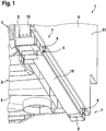
Figur 1 eine Ansicht eines Haushaltsgeräts mit einem Gehäuse, welches eine aus einem Basisträger und mindestens einem Rahmenelement bestehende Tragstruktur und mindestens ein von der Tragstruktur gehaltenes Abdeckflächenelement aufweist, -
Figur 2 eine Detailschnittansicht der Tragstruktur, wobei diese ein Dämpfungselement in einer ersten Ausführungsform aufweist, -
Figur 3 die Tragstruktur mit einem Dämpfungselement in einer zweiten Ausführungsform, und -
Figur 4 der Basisträger der Tragstruktur des Haushaltsgeräts, wobei an dem Basisträger das Dämpfungselement vorgesehen ist. - Die
Figur 1 zeigt eine Ansicht eines Haushaltsgeräts, wie z. B. eines wasserführenden Haushaltsgeräts, das im vorliegenden Ausführungsbeispiel als Geschirrspülmaschine ausgebildet ist. Das wasserführende Haushaltsgerät 1 weist ein Gehäuse 2 auf, das aus einer Tragstruktur 3 und mindestens einem Abdeckflächenelement 4 besteht. Üblicherweise weist das Haushaltsgerät 1 mehrere Abdeckflächenelemente 4 auf; dieFigur 1 zeigt jedoch lediglich eines dieser Abdeckflächenelemente 4. Das Abdeckflächenelement 4 weist mindestens eine Sichtfläche auf, welche von außerhalb des Haushaltsgeräts 1 sichtbar ist und z. B. der Seitenverkleidung des wasserführenden Haushaltsgeräts 1 dient. Das Abdeckflächenelement 4 bildet demnach eine Außenseite beziehungsweise Außenfläche des Haushaltsgeräts 1. - Die Tragstruktur 3 besteht aus einem Basisträger 5, an welchem auch ein hier nicht dargestellter Fuß des Haushaltsgeräts 1 ausgebildet sein kann. Neben dem Basisträger 5 weist die Tragstruktur 3 mindestens ein Rahmenelement 6 auf. Der Basisträger 5 bildet eine Unterseite des Haushaltsgeräts 1. Das Rahmenelement 6 ist üblicherweise auf dem Basisträger 5 angeordnet. Das Abdeckflächenelement 4 wird von der Tragstruktur 3, welche von dem Basisträger 5 und dem Rahmenelement 6 gebildet ist, gehalten beziehungsweise abgestützt. In dem in der
Figur 1 dargestellten Ausführungsbeispiel ist das Abdeckflächenelement 4 in zwei Befestigungsbereichen 7 an der Tragstruktur 3 beziehungsweise dem Basisträger 5 gehalten. Selbstverständlich können neben den beiden dargestellten Befestigungsbereichen 7 weitere, hier nicht dargestellte Befestigungsbereiche 7 vorliegen, um das Abdeckflächenelement 4 sicher an der Tragstruktur 3 zu halten. In dem Befestigungsbereich 7 weist das Abdeckflächenelement 4 jeweils einen Befestigungszapfen 8 auf, welcher mit einem Gegenelement 9 zusammenwirkt beziehungsweise in dieses eingreift. Das Gegenelement 9 liegt hier als Ausnehmung in dem Basisträger 5 vor. - Die
Figur 1 zeigt, dass die Kombination aus Befestigungszapfen 8 und Gegenelement 9 ein gewisses Spiel aufweist, so dass die Befestigungszapfen 8 in Normalenrichtung des Abdeckflächenelements 4 beweglich sind. Dies ist notwendig, da eine Montage des Abdeckflächenelements 4 ansonsten nicht möglich wäre. Die Montage erfolgt, indem die Befestigungszapfen 8 in die Gegenelemente 9 eingesetzt werden, das Abdeckflächenelement 4 nach oben beziehungsweise in Richtung der Tragstruktur 3 geschwenkt und anschließend mit einem hier nicht dargestellte Mittel an der Tragstruktur 3 verrastet wird. Auch nach dem Verrasten ist somit häufig ein gewisses Spiel des Abdeckflächenelements 4 beziehungsweise dessen Befestigungszapfen 8 möglich. Daher wird bei den aus dem Stand der Technik bekannten Haushaltsgeräten 1 häufig ein zusätzliches Element verwendet, beispielsweise ein Vlies, eine Bitumenmatte und/oder ein Styroporelement, mit welchem das Abdeckflächenelement 4 in Bezug auf die Tragstruktur 3 besser fixiert beziehungsweise festgesetzt werden soll. - Dies ist insbesondere notwendig, weil das Abdeckflächenelement 4 nicht flächig auf der Tragstruktur 3 aufliegt, sondern lediglich auf Streben 10, welche in der
Figur 1 angedeutet sind. Die Tragstruktur 3 weist demnach einen rahmenartigen Aufbau auf. In dem Teilbereich des Abdeckflächenelements 4, in welchem das Abdeckflächenelement 4 nicht auf der Tragstruktur 3 aufliegt beziehungsweise unmittelbar aufliegt, liegt mindestens eine schwingungsfähige Schwingungsfläche 11 vor. Diese kann beispielsweise durch Vibrationen des Haushaltsgeräts 1 oder äußere Einflüsse zu einer Schwingung angeregt werden. Somit können in diesem Fall Geräusche entstehen, welche einen negativen Eindruck hinsichtlich der Qualität des Haushaltsgeräts 1 erzeugen können. - Um die Schwingung der Schwingungsfläche 11 des Abdeckflächenelements 4 möglichst kostengünstig zu unterbinden beziehungsweise zu dämpfen, wird ein Dämpfungselement 12 an der Tragstruktur 3 vorgesehen, welches die Schwingungsfläche 11 verkleinernd und damit schwingungsdämpfend an dem Abdeckflächenelement 4 anliegt. Die Tragstruktur 3 mit dem Dämpfungselement 12 ist in der
Figur 2 gezeigt. Anhand derFigur 2 wird deutlich, dass das Dämpfungselement 12 einstückig mit der Tragstruktur 3 ausgebildet sein soll. Beispielsweise ist das Dämpfungselement 12 in einem Spritzgussverfahren an die Tragstruktur 3 angespritzt. Dabei kann das Dämpfungselement 12 materialeinheitlich mit der Tragstruktur 3 ausgebildet sein. Alternativ kann es jedoch auch aus einem anderen Material bestehen. Beispielsweise ist das Dämpfungselement 12 aus einem Elastomer oder einem Kunststoffschaum hergestellt. DieFigur 2 macht nochmals deutlich, dass das Abdeckflächenelement 4 in einem Befestigungsbereich 7 an der Tragstruktur 3 gehalten ist. Weil das Abdeckflächenelement 4 in dem Befestigungsbereich 7 ohnehin auf der Tragstruktur 3 aufliegt, liegt hier keine Schwingungsfläche 11 vor. Diese befindet sich üblicherweise in einem Teilbereich, in welchem das Abdeckflächenelement 4 nicht auf der Tragstruktur 3 aufliegt. DieFigur 2 zeigt, dass das Dämpfungselement 12 außerhalb des Befestigungsbereichs 7 an dem Abdeckflächenelement 4 anliegt. Auf diese Weise wird erreicht, dass die Schwingungsfläche 11 verkleinert ist. - Das Dämpfungselement 12 ist derart ausgebildet, dass es elastisch an dem Abdeckflächenelement 4 beziehungsweise der Schwingungsfläche 11 anliegt. Dabei kann es vorgesehen sein, dass dieses Anliegen mit einer Vorspannung erfolgt. Das bedeutet, dass das Dämpfungselement 12 auch in einer Ruhestellung des Abdeckflächenelements 4, also wenn dieses nicht durch eine Schwingung ausgelenkt ist, mit einer bestimmten Kraft an dem Abdeckflächenelement 4 anliegt. Auf diese Weise kann das Abdeckflächenelement 4 nicht nur nicht in Richtung des Dämpfungselements 12 bewegt werden, es wird vielmehr erreicht, dass auch bei einer Schwingung des Abdeckflächenelements 4 beziehungsweise der Schwingungsfläche 11 das Dämpfungselement 12 der Bewegung der Schwingungsfläche 11 folgt und stets an dieser anliegt. Auf diese Weise wird die Schwingung der Schwingungsfläche 11 spätestens bei einer Bewegung der Schwingungsfläche 11 auf das Dämpfungselement 12 zu gedämpft.
- Das Dämpfungselement 12 weist einen in Richtung des Abdeckflächenelements 4 kleiner werdenden Querschnitt auf. Es liegt demnach als Dämpfungslippe vor. Auf diese Weise kann besonders einfach erreicht werden, dass das Dämpfungselement 12 elastisch ist und ggf. mit Vorspannung dem Abdeckflächenelement 4 entgegentritt. Wenn das Dämpfungselement 12 als Dämpfungslippe ausgeführt ist, so kann es aus dem Grundmaterial der Tragstruktur 3 an diese angespritzt werden. Der benötigte Hinterschnitt kann in einem Herstellungswerkzeug zwangsentformt werden.
- Generell kann es vorgesehen sein, dass sich das Dämpfungselement 12 in einer Richtung über die gesamte Seite des Abdeckflächenelements 4 erstreckt. Dies gilt insbesondere für eine vertikale Richtung des Haushaltsgeräts 1. Auf diese Weise kann zusätzlich erreicht werden, dass ein Arbeitsgeräusch des Haushaltsgeräts 1 reduziert wird, weil der Schall nicht an dem Dämpfungselement 12 vorbei gelangt beziehungsweise von diesem gedämpft wird. Dies gilt insbesondere, wenn das Dämpfungselement 12 vorne an dem Haushaltsgerät 1, also im Bereich einer Türe (nicht dargestellt) des Haushaltsgeräts 1 angeordnet ist.
- Alternativ kann es selbstverständlich auch vorgesehen sein, dass mehrere voneinander beabstandete Dämpfungselemente 12 vorgesehen sind. Diese liegen in Dämpfungsbereichen an dem Abdeckflächenelement 4 an. Diese Dämpfungsbereiche können vorteilhafterweise entsprechend den Schwingungseigenschaften des Abdeckflächenelements 4 angeordnet sein. Auf diese Weise können beispielsweise kostengünstig lediglich einzelne Frequenzen der Schwingung gedämpft werden oder lediglich besonders schwingungsanfällige Bereiche des Abdeckflächenelements 4 von dem Dämpfungselement 12 beaufschlagt werden.
- Die
Figur 3 zeigt eine weitere Ausführungsform des Dämpfungselements 12. Hier ist gezeigt, dass das eleastische Dämpfungselement 12 in einem Spritzgussverfahren an die Tragstruktur 3 angespritzt ist. Dabei besteht das Dämpfungselement 12 vorzugsweise aus einem anderen Material als die Tragstruktur 3, so dass das Spritzgussverfahren ein Mehrkomponenten-Spritzgussverfahren ist. Das für das Dämpfungselement 12 verwendete Material ist ein weiches beziehungsweise elastisches Material. Beispielsweise kann ein thermoplastisches Elastomer (TPE) an die Tragstruktur 3 angespritzt werden oder es kann ein Schaum (beispielsweise Silikonschaum oder Polyurethanschaum) aufgebracht werden. Die Tragstruktur 3 besteht vorzugsweise aus Polypropylen. - Die
Figur 4 zeigt eine weitere Ausführungsform des Dämpfungselements 12. Die hier vorgesehenen Dämpfungselemente 12 sind an dem Basisträger 5 angespritzt und elastisch ausgeführt. Die Dämpfungselemente 12 sorgen in diesem Fall dafür, dass das Spiel der Befestigungszapfen 8 in den Gegenelementen 9 (wie inFigur 1 dargestellt) verringert wird, weil die Dämpfungselemente 12 stets das Abdeckflächenelement 4 nach außen drücken. Beim Montieren des Abdeckflächenelements 4 werden die Dämpfungselemente 12 elastisch deformiert und versuchen anschließend in ihre Ausgangslage zurückzukehren. Dabei drängen sie das Abdeckflächenelement 4 von dem Basisträger 5 beziehungsweise der Tragstruktur 3 fort. Zusammen mit dem Befestigungszapfen 8 und dem Gegenelementen 9 halten sie somit das Abdeckflächenelement 4 in einem definierten Abstand zu der Tragstruktur 3, so dass keine Bewegung des Abdeckflächenelements 4 mehr möglich ist. Bei einer solchen Ausführungsform ist zu beachten, dass die Elastizität des Dämpfungselements 12 ausreichend hoch ist, um eine Beschädigung des Abdeckflächenelements 4 während eines Transports des Haushaltsgeräts 1 zu verhindern. - Mit dem vorgeschlagenen Haushaltsgerät 1 kann das Vibrieren des Abdeckflächenelements 4 vermieden beziehungsweise verringert werden. Das Haushaltsgerät 1 wirkt also wertiger beziehungsweise weist einen deutlich höheren Qualitätseindruck auf. Klappern beziehungsweise Scheppern des Abdeckflächenelements 4 wird vermieden. Dies erfolgt dabei mit einer im Vergleich zu bekannten Maßnahmen kostengünstigen Vorgehensweise, nämlich dem Vorsehen des mindestens einen Dämpfungselements 12 an der Tragstruktur 3. Insbesondere wenn das Dämpfungselement 12 einstückig mit der Tragstruktur 3 ausgebildet ist, können bereits vorhandene Werkzeuge verwendet werden. Ist das Dämpfungselement 12 materialeinheitlich mit der Tragstruktur 3 ausgebildet, so wird außerdem kein zusätzlicher Werkstoff benötigt. Das Dämpfungselement 12 erlaubt zudem größere Toleranzen bei der Herstellung der Tragstruktur 3 und des Abdeckflächenelements 4. Bei der Montage des Abdeckflächenelements 4 an der Tragstruktur 3 können folglich größere Spalte zugelassen werden, weil das Dämpfungselement 12 das Abdeckflächenelement 4 stets nach außen drückt und somit in eine definierte Position bringen. Insgesamt wird der Qualitätseindruck des Haushaltsgeräts 1 merklich verbessert, weil die Haptik allgemein verbessert wird.
Claims (11)
- Haushaltsgerät (1), insbesondere wasserführendes Haushaltsgerät (1), mit einem Gehäuse (2), welches eine Tragstruktur (3) und mindestens ein von der Tragstruktur (3) gehaltenes und/oder abgestütztes Abdeckflächenelement (4) aufweist, dadurch gekennzeichnet, dass die Tragstruktur (3) mindestens ein elastisches Dämpfungselement (12) aufweist, welches schwingungsdämpfend an dem Abdeckflächenelement (4) anliegt.
- Haushaltsgerät nach Anspruch 1, dadurch gekennzeichnet, dass das Dämpfungselement (12) mit einer Vorspannung an dem Abdeckflächenelement (4) anliegt.
- Haushaltsgerät (1) nach einem der Ansprüche 1 oder2, dadurch gekennzeichnet, dass das Abdeckflächenelement (4) in einem Befestigungsbereich (7) an der Tragstruktur (3) gehalten und/oder abgestützt ist und dass das Dämpfungselement (12) außerhalb des Befestigungsbereichs (7) an dem Abdeckflächenelement (4) anliegt.
- Haushaltsgerät (1) nach einem der Ansprüche 1 bis 3, dadurch gekennzeichnet, dass das Dämpfungselement (12) einstückig mit der Tragstruktur (3) ausgebildet ist.
- Haushaltsgerät (1) nach Anspruch 4, dadurch gekennzeichnet, dass das Dämpfungselement (12) in einem Spritzgussverfahren an die Tragstruktur (3) angespritzt ist.
- Haushaltsgerät (1) nach einem der vorhergehenden Ansprüche, dadurch gekennzeichnet, dass das Dämpfungselement (12) materialeinheitlich mit der Tragstruktur (3) ausgebildet ist und/oder aus einem Elastomer, insbesondere thermoplastischen Elastomer, oder einem Kunststoffschaum, insbesondere Silikonschaum oder Polyurethanschaum, besteht.
- Haushaltsgerät (1) nach einem der vorhergehenden Ansprüche, dadurch gekennzeichnet, dass das Dämpfungselement (12) einen in Richtung des Abdeckflächenelements (4) kleiner werdenden Querschnitt aufweist.
- Haushaltsgerät (1) nach einem der vorhergehenden Ansprüche, dadurch gekennzeichnet, dass sich das Dämpfungselement (12) in einer Richtung über die gesamte Seite des Abdeckflächenelements (4), insbesondere in vertikaler Richtung des Haushaltsgeräts (1), erstreckt.
- Haushaltsgerät (1) nach einem der vorhergehenden Ansprüche, dadurch gekennzeichnet, dass mehrere, voneinander beabstandete Dämpfungselemente (12) vorgesehen sind, die in Dämpfungsbereichen an dem Abdeckflächenelement (4) anliegen, wobei die Dämpfungsbereiche insbesondere entsprechend der Schwingungseigenschaften des Abdeckflächenelements (4) angeordnet sind.
- Haushaltsgerät (1) nach einem der vorhergehenden Ansprüche, dadurch gekennzeichnet, dass die Tragstruktur (3) zumindest bereichsweise aus Kunststoff, insbesondere einem Thermoplast, bevorzugt Polypropylen, und/oder das Abdeckflächenelement (4) aus Metall, insbesondere Blech, bestehen.
- Haushaltsgerät (1) nach einem der vorhergehenden Ansprüche, dadurch gekennzeichnet, dass die Tragstruktur (3) einen Basisträger (5) und mindestens ein an dem Basisträger (5) angeordnetes Rahmenelement (6) aufweist.
Applications Claiming Priority (1)
| Application Number | Priority Date | Filing Date | Title |
|---|---|---|---|
| DE102011004555A DE102011004555A1 (de) | 2011-02-23 | 2011-02-23 | Haushaltsgerät |
Publications (2)
| Publication Number | Publication Date |
|---|---|
| EP2491846A2 true EP2491846A2 (de) | 2012-08-29 |
| EP2491846A3 EP2491846A3 (de) | 2017-12-27 |
Family
ID=45560761
Family Applications (1)
| Application Number | Title | Priority Date | Filing Date |
|---|---|---|---|
| EP12153593.4A Withdrawn EP2491846A3 (de) | 2011-02-23 | 2012-02-02 | Haushaltsgerät |
Country Status (2)
| Country | Link |
|---|---|
| EP (1) | EP2491846A3 (de) |
| DE (1) | DE102011004555A1 (de) |
Cited By (1)
| Publication number | Priority date | Publication date | Assignee | Title |
|---|---|---|---|---|
| WO2014056721A1 (en) * | 2012-10-08 | 2014-04-17 | Arcelik Anonim Sirketi | Dishwasher with improved leak-proofing |
Families Citing this family (1)
| Publication number | Priority date | Publication date | Assignee | Title |
|---|---|---|---|---|
| CN111277073B (zh) * | 2018-12-04 | 2022-10-04 | 青岛海尔洗碗机有限公司 | 一种减振电机安装结构及洗碗机 |
Family Cites Families (4)
| Publication number | Priority date | Publication date | Assignee | Title |
|---|---|---|---|---|
| DE4443918C2 (de) * | 1994-12-09 | 2000-05-18 | Bsh Bosch Siemens Hausgeraete | Haushaltgerät mit einem Rahmen |
| DE10003185C1 (de) * | 2000-01-25 | 2001-03-15 | Miele & Cie | Haushaltgerät mit einem Lärmdämmelement |
| KR20090028032A (ko) * | 2007-09-13 | 2009-03-18 | 엘지전자 주식회사 | 세탁 장치 |
| US20090205378A1 (en) * | 2008-02-15 | 2009-08-20 | Electrolux Home Products, Inc. | Washing appliance and associated method |
-
2011
- 2011-02-23 DE DE102011004555A patent/DE102011004555A1/de not_active Withdrawn
-
2012
- 2012-02-02 EP EP12153593.4A patent/EP2491846A3/de not_active Withdrawn
Non-Patent Citations (1)
| Title |
|---|
| None |
Cited By (2)
| Publication number | Priority date | Publication date | Assignee | Title |
|---|---|---|---|---|
| WO2014056721A1 (en) * | 2012-10-08 | 2014-04-17 | Arcelik Anonim Sirketi | Dishwasher with improved leak-proofing |
| US9332888B2 (en) | 2012-10-08 | 2016-05-10 | Arcelik Anonim Sirketi | Dishwasher with improved leak-proofing |
Also Published As
| Publication number | Publication date |
|---|---|
| DE102011004555A1 (de) | 2012-08-23 |
| EP2491846A3 (de) | 2017-12-27 |
Similar Documents
| Publication | Publication Date | Title |
|---|---|---|
| DE19925944C2 (de) | Lautsprecher mit einem frontseitig aufgesetzten Dichtelement und Verfahren zur Herstellung eines solchen Lautsprechers | |
| DE202010002297U1 (de) | Schwingungsdämpfer | |
| DE10228395C1 (de) | Schall-Absorber | |
| DE102015116350A1 (de) | Befestigungsmodul zur Befestigung eines Gebläsemotors sowie Heizungs-, Lüftungs- und/oder Klimaanlagenmodul | |
| DE10245816B4 (de) | Keder | |
| DE102011004555A1 (de) | Haushaltsgerät | |
| EP0042909A2 (de) | Hydraulisch dämpfendes Einkammerlager | |
| EP4125530A1 (de) | Isolationsvorrichtung, haushaltsgerät und verfahren | |
| DE4228169C1 (de) | Schall absorbierendes Verkleidungselement | |
| DE202010007559U1 (de) | Vorrichtung zur Halterung einer eine Haltestange aufweisenden Komponente | |
| WO2008043563A1 (de) | A blaue fach für ein kraftfahrzeug und verfahren zu dessen herstellung | |
| DE102017203417B4 (de) | Gurtaufroller mit einem geräuschgedämpften Beschleunigungssensor | |
| DE19928812C2 (de) | Lautsprecher zum Einbau in Kraftfahrzeugen | |
| DE10008565A1 (de) | Befestigungsclip | |
| EP3138688A1 (de) | Verfahren zum herstellen eines formteils zur schalldämmung einer einbauvorrichtung | |
| DE102017108429B4 (de) | Lenkrad für ein Kraftfahrzeug und Verfahren zum Herstellen eines Lenkrades für ein Kraftfahrzeug | |
| WO2019110627A1 (de) | Trägerbaugruppe mit anbringungsbereich zum dämpfen einer akustischen anregung | |
| DE10211631B4 (de) | Ausstattungsteil, insbesondere zur Innenausstattung in Fahrzeugen | |
| EP2129933B1 (de) | Träger zur halterung eines schwingungserzeugenden bauteils | |
| DE3926572C2 (de) | ||
| WO2009106115A1 (de) | Vorrichtung zur befestigung eines lautsprechers | |
| EP1133413A1 (de) | Steuergerät für den insassenschutz in einem fahrzeug sowie verfahren zum herstellen eines steuergeräts | |
| DE19902874C1 (de) | Badewanne | |
| DE102010003621A1 (de) | Gehäuseelement für eine Heizungs-, Lüftungs- und/oder Klima-Anlage | |
| DE102016120731A1 (de) | Interieurteil mit einem Träger und einem starren Verkleidungsteil |
Legal Events
| Date | Code | Title | Description |
|---|---|---|---|
| PUAI | Public reference made under article 153(3) epc to a published international application that has entered the european phase |
Free format text: ORIGINAL CODE: 0009012 |
|
| AK | Designated contracting states |
Kind code of ref document: A2 Designated state(s): AL AT BE BG CH CY CZ DE DK EE ES FI FR GB GR HR HU IE IS IT LI LT LU LV MC MK MT NL NO PL PT RO RS SE SI SK SM TR |
|
| AX | Request for extension of the european patent |
Extension state: BA ME |
|
| RAP1 | Party data changed (applicant data changed or rights of an application transferred) |
Owner name: BSH HAUSGERAETE GMBH |
|
| PUAL | Search report despatched |
Free format text: ORIGINAL CODE: 0009013 |
|
| AK | Designated contracting states |
Kind code of ref document: A3 Designated state(s): AL AT BE BG CH CY CZ DE DK EE ES FI FR GB GR HR HU IE IS IT LI LT LU LV MC MK MT NL NO PL PT RO RS SE SI SK SM TR |
|
| AX | Request for extension of the european patent |
Extension state: BA ME |
|
| RIC1 | Information provided on ipc code assigned before grant |
Ipc: A47L 15/42 20060101AFI20171117BHEP Ipc: D06F 39/12 20060101ALI20171117BHEP |
|
| 17P | Request for examination filed |
Effective date: 20180627 |
|
| RBV | Designated contracting states (corrected) |
Designated state(s): AL AT BE BG CH CY CZ DE DK EE ES FI FR GB GR HR HU IE IS IT LI LT LU LV MC MK MT NL NO PL PT RO RS SE SI SK SM TR |
|
| RIC1 | Information provided on ipc code assigned before grant |
Ipc: D06F 39/12 20060101ALI20191227BHEP Ipc: A47L 15/42 20060101AFI20191227BHEP |
|
| GRAP | Despatch of communication of intention to grant a patent |
Free format text: ORIGINAL CODE: EPIDOSNIGR1 |
|
| INTG | Intention to grant announced |
Effective date: 20200210 |
|
| STAA | Information on the status of an ep patent application or granted ep patent |
Free format text: STATUS: THE APPLICATION IS DEEMED TO BE WITHDRAWN |
|
| 18D | Application deemed to be withdrawn |
Effective date: 20200623 |