EP2491757B1 - Method and apparatus for a two-way relaying scheme with physical layer network coding - Google Patents
Method and apparatus for a two-way relaying scheme with physical layer network coding Download PDFInfo
- Publication number
- EP2491757B1 EP2491757B1 EP10775991.2A EP10775991A EP2491757B1 EP 2491757 B1 EP2491757 B1 EP 2491757B1 EP 10775991 A EP10775991 A EP 10775991A EP 2491757 B1 EP2491757 B1 EP 2491757B1
- Authority
- EP
- European Patent Office
- Prior art keywords
- wtru
- bits
- signal
- received
- time slot
- Prior art date
- Legal status (The legal status is an assumption and is not a legal conclusion. Google has not performed a legal analysis and makes no representation as to the accuracy of the status listed.)
- Not-in-force
Links
Images


Classifications
-
- H—ELECTRICITY
- H04—ELECTRIC COMMUNICATION TECHNIQUE
- H04L—TRANSMISSION OF DIGITAL INFORMATION, e.g. TELEGRAPHIC COMMUNICATION
- H04L27/00—Modulated-carrier systems
- H04L27/32—Carrier systems characterised by combinations of two or more of the types covered by groups H04L27/02, H04L27/10, H04L27/18 or H04L27/26
- H04L27/34—Amplitude- and phase-modulated carrier systems, e.g. quadrature-amplitude modulated carrier systems
-
- H—ELECTRICITY
- H04—ELECTRIC COMMUNICATION TECHNIQUE
- H04B—TRANSMISSION
- H04B7/00—Radio transmission systems, i.e. using radiation field
- H04B7/14—Relay systems
- H04B7/15—Active relay systems
- H04B7/155—Ground-based stations
- H04B7/15521—Ground-based stations combining by calculations packets received from different stations before transmitting the combined packets as part of network coding
-
- H—ELECTRICITY
- H04—ELECTRIC COMMUNICATION TECHNIQUE
- H04B—TRANSMISSION
- H04B7/00—Radio transmission systems, i.e. using radiation field
- H04B7/24—Radio transmission systems, i.e. using radiation field for communication between two or more posts
- H04B7/26—Radio transmission systems, i.e. using radiation field for communication between two or more posts at least one of which is mobile
- H04B7/2603—Arrangements for wireless physical layer control
- H04B7/2606—Arrangements for base station coverage control, e.g. by using relays in tunnels
-
- H—ELECTRICITY
- H04—ELECTRIC COMMUNICATION TECHNIQUE
- H04L—TRANSMISSION OF DIGITAL INFORMATION, e.g. TELEGRAPHIC COMMUNICATION
- H04L1/00—Arrangements for detecting or preventing errors in the information received
- H04L1/12—Arrangements for detecting or preventing errors in the information received by using return channel
- H04L1/16—Arrangements for detecting or preventing errors in the information received by using return channel in which the return channel carries supervisory signals, e.g. repetition request signals
- H04L1/1607—Details of the supervisory signal
-
- H—ELECTRICITY
- H04—ELECTRIC COMMUNICATION TECHNIQUE
- H04B—TRANSMISSION
- H04B7/00—Radio transmission systems, i.e. using radiation field
- H04B7/24—Radio transmission systems, i.e. using radiation field for communication between two or more posts
- H04B7/26—Radio transmission systems, i.e. using radiation field for communication between two or more posts at least one of which is mobile
- H04B7/2643—Radio transmission systems, i.e. using radiation field for communication between two or more posts at least one of which is mobile using time-division multiple access [TDMA]
- H04B7/2656—Radio transmission systems, i.e. using radiation field for communication between two or more posts at least one of which is mobile using time-division multiple access [TDMA] for structure of frame, burst
-
- H—ELECTRICITY
- H04—ELECTRIC COMMUNICATION TECHNIQUE
- H04L—TRANSMISSION OF DIGITAL INFORMATION, e.g. TELEGRAPHIC COMMUNICATION
- H04L1/00—Arrangements for detecting or preventing errors in the information received
- H04L2001/0092—Error control systems characterised by the topology of the transmission link
- H04L2001/0097—Relays
Definitions
- a relay node may create new cells, distinguishable and separate from the cells of a donor-evolved NodeB (eNB), where the donor-eNB may support a Un interface to support eNB to RN communication.
- eNB donor-evolved NodeB
- an RN may appear as an eNB. That is, the presence of an RN in its communication path to the donor-eNB may be transparent to the WTRU.
- An RN may be an eNB that has a wireless in-band backhaul link back to the donor-eNB by using an LTE or LTE-A air interface within the International Mobile Telecommunications (IMT) spectrum allocation.
- IMT International Mobile Telecommunications
- a two-way communications system with two transceivers and one relay node may take four time slots to complete a message exchange, assuming time division duplex (TDD) half duplex mode and no direct link between two transceivers. It would be desirable to have a method and apparatus for implementing a relay scheme that may use a lower number of time slots and may also have a low level of complexity.
- TDD time division duplex
- the patent document US2010/0246708 discloses a method and system wherein a relay node combines, hierarchically modulates and broadcasts decoded signals previously received from different mobile stations.
- a two-way relay wireless communication method and device may combine multiple bit steams, for one source node and two target nodes, and broadcasting a network coded combined bit sequence to reduce the number of time slots for transmission.
- a first device may receive a signal from the source node and a target node simultaneously in a time slot.
- the first device may receive subsequent signals from the source node and multiple target nodes simultaneously in successive time slots.
- Hierarchical modulation may be applied to the received signals.
- the first device may decode the received signals and generate a plurality of intermediate bit sequences (IBS)s for a broadcast transmission.
- the generated IBSs may be grouped according to a channel condition.
- a second device may transmit a signal in a first time slot and receive a broadcast signal in a second time slot.
- the broadcast signal may include network coded data for one or more target nodes.
- the second device may be configured to decode a portion of the broadcast signal that is intended for the
- the present Invention relates to a wireless communication method, to a relay node and to a wireless transmit and receive unit according to the accompanying claims.
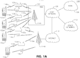
- FIG. 1A is a diagram of an example communications system 100 in which one or more disclosed embodiments may be implemented.
- the communications system 100 may be a multiple access system that provides content, such as voice, data, video, messaging, broadcast, etc., to multiple wireless users.
- the communications system 100 may enable multiple wireless users to access such content through the sharing of system resources, including wireless bandwidth.
- the communications system 100 may employ one or more channel access methods, such as code division multiple access (CDMA), time division multiple access (TDMA), frequency division multiple access (FDMA), orthogonal FDMA (OFDMA), single-carrier FDMA (SC-FDMA), and the like.
- CDMA code division multiple access
- TDMA time division multiple access
- FDMA frequency division multiple access
- OFDMA orthogonal FDMA
- SC-FDMA single-carrier FDMA
- the communications system 100 may include wireless transmit/receive units (WTRU)s 102a, 102b, 102c, 102d, relay nodes (RN)s 103a, 103b, 103c, 103d, a radio access network (RAN) 104, a core network 106, a public switched telephone network (PSTN) 108, the Internet 110, and other networks 112, though it will be appreciated that the disclosed embodiments contemplate any number of WTRUs, base stations, networks, and/or network elements.
- Each of the WTRUs 102a, 102b, 102c, 102d may be any type of device configured to operate and/or communicate in a wireless environment.
- the WTRUs 102a, 102b, 102c, 102d may be configured to transmit and/or receive wireless signals and may include user equipment (UE), a mobile station, a fixed or mobile subscriber unit, a pager, a cellular telephone, a personal digital assistant (PDA), a smartphone, a laptop, a netbook, a personal computer, a wireless sensor, consumer electronics, and the like.
- UE user equipment
- PDA personal digital assistant
- smartphone a laptop
- a netbook a personal computer
- the communication system 100 may comprise of all WTRUs, BSs, RNs, or any wireless device that may receive and transmit data.
- the communications system 100 may also include a base station 114a and a base station 114b.
- Each of the base stations 114a, 114b may be any type of device configured to wirelessly interface with at least one of the WTRUs 102a, 102b, 102c, 102d to facilitate access to one or more communication networks, such as the core network 106, the Internet 110, and/or the networks 112.
- the base stations 114a, 114b may be a base transceiver station (BTS), a Node-B, an eNode B, a Home Node B, a Home eNode B, a site controller, an access point (AP), a wireless router, and the like. While the base stations 114a, 114b are each depicted as a single element, it will be appreciated that the base stations 114a, 114b may include any number of interconnected base stations and/or network elements.
- the base station 114a may be part of the RAN 104, which may also include other base stations and/or network elements (not shown), such as a base station controller (BSC), a radio network controller (RNC), relay nodes, etc.
- BSC base station controller
- RNC radio network controller
- the base station 114a and/or the base station 114b may be configured to transmit and/or receive wireless signals within a particular geographic region, which may be referred to as a cell (not shown).
- the cell may further be divided into cell sectors.
- the cell associated with the base station 114a may be divided into three sectors.
- the base station 114a may include three transceivers, i.e., one for each sector of the cell.
- the base station 114a may employ multiple-input multiple output (MIMO) technology and, therefore, may utilize multiple transceivers for each sector of the cell.
- MIMO multiple-input multiple output
- the base stations 114a, 114b may communicate with one or more of the RNs 103a, 103b, 103c, 103d over an air interface 116a, which may be any suitable wireless communication link (e.g., radio frequency (RF), microwave, infrared (IR), ultraviolet (UV), visible light, etc.).
- the air interface 116a may be established using any suitable radio access technology (RAT).
- RAT radio access technology
- the RNs 103a, 103b, 103c, 103d may communicate with one or more of the WTRUs 102a, 102b, 102c, 102d over an air interface 116b, which may be any suitable wireless communication link (e.g., radio frequency (RF), microwave, infrared (IR), ultraviolet (UV), visible light, etc.).
- the air interface 116b may be established using any suitable radio access technology (RAT).
- RAT radio access technology
- the base stations 114a, 114b may communicate with one or more of the WTRUs 102a, 102b, 102c, 102d over an air interface 116c, which may be any suitable wireless communication link (e.g., radio frequency (RF), microwave, infrared (IR), ultraviolet (UV), visible light, etc.).
- the air interface 116c may be established using any suitable radio access technology (RAT).
- RAT radio access technology
- the communications system 100 may be a multiple access system and may employ one or more channel access schemes, such as CDMA, TDMA, FDMA, OFDMA, SC-FDMA, and the like.
- the base station 114a in the RAN 104, the WTRUs 102a, 102b, 102c, and the RNs 103a, 103b, 103c may implement a radio technology such as Universal Mobile Telecommunications System (UMTS) Terrestrial Radio Access (UTRA), which may establish the air interfaces 116a, 116b, 116c using wideband CDMA (WCDMA).
- UMTS Universal Mobile Telecommunications System
- UTRA Wideband CDMA
- WCDMA may include communication protocols such as High-Speed Packet Access (HSPA) and/or Evolved HSPA (HSPA+).
- HSPA may include High-Speed Downlink Packet Access (HSDPA) and/or High-Speed Uplink Packet Access (HSUPA).
- HSPA High-Speed Packet Access
- HSDPA High-Speed Downlink Packet Access
- HSUPA High-Speed Uplink Packet Access
- the base station 114a, the WTRUs 102a, 102b, 102c, and the RNs 103a, 103b, 103c may implement a radio technology such as Evolved UMTS Terrestrial Radio Access (E-UTRA), which may establish the air interfaces 116a, 116b, 116c using Long Term Evolution (LTE) and/or LTE-Advanced (LTE-A).
- E-UTRA Evolved UMTS Terrestrial Radio Access
- LTE Long Term Evolution
- LTE-A LTE-Advanced
- the base station 114a, the WTRUs 102a, 102b, 102c, and the RNs 103a, 103b, 103c may implement radio technologies such as IEEE 802.16 (i.e., Worldwide Interoperability for Microwave Access (WiMAX)), CDMA2000, CDMA2000 1X, CDMA2000 EV-DO, Interim Standard 2000 (IS-2000), Interim Standard 95 (IS-95), Interim Standard 856 (IS-856), Global System for Mobile communications (GSM), Enhanced Data rates for GSM Evolution (EDGE), GSM EDGE (GERAN), and the like.
- IEEE 802.16 i.e., Worldwide Interoperability for Microwave Access (WiMAX)
- CDMA2000, CDMA2000 1X, CDMA2000 EV-DO Code Division Multiple Access 2000
- IS-95 Interim Standard 95
- IS-856 Interim Standard 856
- GSM Global System for Mobile communications
- GSM Global System for Mobile communications
- EDGE Enhanced Data rates for GSM Evolution
- the base station 114b in FIG. 1A is a source node and may be a wireless router, a Home Node B, a WTRU, a Home eNode B, or an access point, for example, and may utilize any suitable RAT for facilitating wireless connectivity in a localized area, such as a place of business, a home, a vehicle, a campus, and the like.
- the base station 114b and the WTRUs 102c, 102d may implement a radio technology such as IEEE 802.11 to establish a wireless local area network (WLAN).
- WLAN wireless local area network
- the base station 114b, the WTRUs 102c, 102d, and the RNs 103c, 103d may implement a radio technology such as IEEE 802.15 to establish a wireless personal area network (WPAN).
- the base station 114b, the WTRUs 102c, 102d, and the RNs 103c, 103d may utilize a cellular-based RAT (e.g., WCDMA, CDMA2000, GSM, LTE, LTE-A, etc.) to establish a picocell or femtocell.
- the base station 114b may have a direct connection to the Internet 110.
- the base station 114b may not be required to access the Internet 110 via the core network 106.
- the RAN 104 may be in communication with the core network 106, which may be any type of network configured to provide voice, data, applications, and/or voice over internet protocol (VoIP) services to one or more of the WTRUs 102a, 102b, 102c, 102d.
- the core network 106 may provide call control, billing services, mobile location-based services, pre-paid calling, Internet connectivity, video distribution, etc., and/or perform high-level security functions, such as user authentication.
- the RAN 104 and/or the core network 106 may be in direct or indirect communication with other RANs that employ the same RAT as the RAN 104 or a different RAT.
- the core network 106 may also be in communication with another RAN (not shown) employing a GSM radio technology.
- the core network 106 may also serve as a gateway for the WTRUs 102a, 102b, 102c, 102d to access the PSTN 108, the Internet 110, and/or other networks 112.
- the PSTN 108 may include circuit-switched telephone networks that provide plain old telephone service (POTS).
- POTS plain old telephone service
- the Internet 110 may include a global system of interconnected computer networks and devices that use common communication protocols, such as the transmission control protocol (TCP), user datagram protocol (UDP) and the internet protocol (IP) in the TCP/IP internet protocol suite.
- the networks 112 may include wired or wireless communications networks owned and/or operated by other service providers.
- the networks 112 may include another core network connected to one or more RANs, which may employ the same RAT as the RAN 104 or a different RAT.
- the WTRUs 102a, 102b, 102c, 102d in the communications system 100 may include multi-mode capabilities, i.e., the WTRUs 102a, 102b, 102c, 102d may include multiple transceivers for communicating with different wireless networks over different wireless links.
- the WTRU 102c shown in FIG. 1A may be configured to communicate with the base station 114a, which may employ a cellular-based radio technology, and with the base station 114b, which may employ an IEEE 802 radio technology.
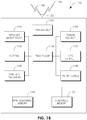
- FIG. 1B is a system diagram of an example WTRU 102.
- the WTRU 102 may include a processor 118, a transceiver 120, a transmit/receive element 122, a speaker/microphone 124, a keypad 126, a display/touchpad 128, non-removable memory 130, removable memory 132, a power source 134, a global positioning system (GPS) chipset 136, and other peripherals 138.
- the WTRU 102 may include any sub-combination of the foregoing elements while remaining consistent with an embodiment.
- the processor 118 may be a general purpose processor, a special purpose processor, a conventional processor, a digital signal processor (DSP), a plurality of microprocessors, one or more microprocessors in association with a DSP core, a controller, a microcontroller, Application Specific Integrated Circuits (ASICs), Field Programmable Gate Array (FPGAs) circuits, any other type of integrated circuit (IC), a state machine, and the like.
- the processor 118 may perform signal coding, data processing, power control, input/output processing, and/or any other functionality that enables the WTRU 102 to operate in a wireless environment.
- the processor 118 may be coupled to the transceiver 120, which may be coupled to the transmit/receive element 122. While FIG. 1B depicts the processor 118 and the transceiver 120 as separate components, it will be appreciated that the processor 118 and the transceiver 120 may be integrated together in an electronic package or chip.
- the transmit/receive element 122 may be configured to transmit signals to, or receive signals from, a base station (e.g., the base station 114a) or an RN over the air interfaces 116b, 116c.
- the transmit/receive element 122 may be an antenna configured to transmit and/or receive RF signals.
- the transmit/receive element 122 may be an emitter/detector configured to transmit and/or receive IR, UV, or visible light signals, for example.
- the transmit/receive element 122 may be configured to transmit and receive both RF and light signals. It will be appreciated that the transmit/receive element 122 may be configured to transmit and/or receive any combination of wireless signals.
- the WTRU 102 may include any number of transmit/receive elements 122. More specifically, the WTRU 102 may employ MIMO technology. Thus, in one embodiment, the WTRU 102 may include two or more transmit/receive elements 122 (e.g., multiple antennas) for transmitting and receiving wireless signals over the air interfaces 116b, 116c.
- the WTRU 102 may include two or more transmit/receive elements 122 (e.g., multiple antennas) for transmitting and receiving wireless signals over the air interfaces 116b, 116c.
- the transceiver 120 may be configured to modulate the signals that are to be transmitted by the transmit/receive element 122 and to demodulate the signals that are received by the transmit/receive element 122.
- the WTRU 102 may have multi-mode capabilities.
- the transceiver 120 may include multiple transceivers for enabling the WTRU 102 to communicate via multiple RATs, such as UTRA and IEEE 802.11, for example.
- the processor 118 of the WTRU 102 may be coupled to, and may receive user input data from, the speaker/microphone 124, the keypad 126, and/or the display/touchpad 128 (e.g., a liquid crystal display (LCD) display unit or organic light-emitting diode (OLED) display unit).
- the processor 118 may also output user data to the speaker/microphone 124, the keypad 126, and/or the display/touchpad 128.
- the processor 118 may access information from, and store data in, any type of suitable memory, such as the non-removable memory 130 and/or the removable memory 132.
- the non-removable memory 130 may include random-access memory (RAM), read-only memory (ROM), a hard disk, or any other type of memory storage device.
- the removable memory 132 may include a subscriber identity module (SIM) card, a memory stick, a secure digital (SD) memory card, and the like.
- SIM subscriber identity module
- SD secure digital
- the processor 118 may access information from, and store data in, memory that is not physically located on the WTRU 102, such as on a server or a home computer (not shown).
- the processor 118 may receive power from the power source 134, and may be configured to distribute and/or control the power to the other components in the WTRU 102.
- the power source 134 may be any suitable device for powering the WTRU 102.
- the power source 134 may include one or more dry cell batteries (e.g., nickel-cadmium (NiCd), nickel-zinc (NiZn), nickel metal hydride (NiMH), lithium-ion (Li-ion), etc.), solar cells, fuel cells, and the like.
- the processor 118 may also be coupled to the GPS chipset 136, which may be configured to provide location information (e.g., longitude and latitude) regarding the current location of the WTRU 102.
- location information e.g., longitude and latitude
- the WTRU 102 may receive location information over the air interface 116 from a base station (e.g., base stations 114a, 114b) and/or determine its location based on the timing of the signals being received from two or more nearby base stations. It will be appreciated that the WTRU 102 may acquire location information by way of any suitable location-determination method while remaining consistent with an embodiment.
- the processor 118 may further be coupled to other peripherals 138, which may include one or more software and/or hardware modules that provide additional features, functionality and/or wired or wireless connectivity.
- the peripherals 138 may include an accelerometer, an e-compass, a satellite transceiver, a digital camera (for photographs or video), a universal serial bus (USB) port, a vibration device, a television transceiver, a hands free headset, a Bluetooth® module, a frequency modulated (FM) radio unit, a digital music player, a media player, a video game player module, an Internet browser, and the like.
- the peripherals 138 may include an accelerometer, an e-compass, a satellite transceiver, a digital camera (for photographs or video), a universal serial bus (USB) port, a vibration device, a television transceiver, a hands free headset, a Bluetooth® module, a frequency modulated (FM) radio unit, a digital music player, a media player, a video game player
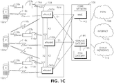
- FIG. 1C is a system diagram of the RAN 104 and the core network 106 according to an embodiment.
- the RAN 104 may employ an E-UTRA radio technology to communicate with the WTRUs 102a, 102b, 102c over the air interface 116c and/or with RNs 103a, 103b, 103c over the air interface 116a.
- the RAN 104 may also be in communication with the core network 106.
- the RAN 104 may include eNode-Bs 140a, 140b, 140c, though it will be appreciated that the RAN 104 may include any number of eNode-Bs while remaining consistent with an embodiment.
- the eNode-Bs 140a, 140b, 140c may each include one or more transceivers for communicating with the WTRUs 102a, 102b, 102c over the air interface 116c and/or with RNs 103a, 103b, 103c over the air interface 116a.
- the eNode-Bs 140a, 140b, 140c may implement MIMO technology.
- the eNode-B 140a for example, may use multiple antennas to transmit wireless signals to, and receive wireless signals from, the WTRU 102a.
- Each of the eNode-Bs 140a, 140b, 140c may be associated with a particular cell (not shown) and may be configured to handle radio resource management decisions, handover decisions, scheduling of users in the uplink and/or downlink, and the like. As shown in FIG. 1C , the eNode-Bs 140a, 140b, 140c may communicate with one another over an X2 interface.
- the RNs 103a, 103b, 103c may communicate with one or more of the WTRUs 102a, 102b, 102c, over an air interface 116b, which may be any suitable wireless communication link (e.g., radio frequency (RF), microwave, infrared (IR), ultraviolet (UV), visible light, etc.).
- the air interface 116b may be established using any suitable radio access technology (RAT).
- RAT radio access technology
- the MME 142 may be connected to each of the eNode-Bs 142a, 142b, 142c in the RAN 104 via an S1 interface and may serve as a control node.
- the MME 142 may be responsible for authenticating users of the WTRUs 102a, 102b, 102c, bearer activation/deactivation, selecting a particular serving gateway during an initial attach of the WTRUs 102a, 102b, 102c, and the like.
- the MME 142 may also provide a control plane function for switching between the RAN 104 and other RANs (not shown) that employ other radio technologies, such as GSM or WCDMA.
- the serving gateway 144 may be connected to each of the eNode Bs 140a, 140b, 140c in the RAN 104 via the S1 interface.
- the serving gateway 144 may generally route and forward user data packets to/from the WTRUs 102a, 102b, 102c.
- the serving gateway 144 may also perform other functions, such as anchoring user planes during inter-eNode B handovers, triggering paging when downlink data is available for the WTRUs 102a, 102b, 102c, managing and storing contexts of the WTRUs 102a, 102b, 102c, and the like.
- the serving gateway 144 may also be connected to the PDN gateway 146, which may provide the WTRUs 102a, 102b, 102c with access to packet-switched networks, such as the Internet 110, to facilitate communications between the WTRUs 102a, 102b, 102c and IP-enabled devices.
- the PDN gateway 146 may provide the WTRUs 102a, 102b, 102c with access to packet-switched networks, such as the Internet 110, to facilitate communications between the WTRUs 102a, 102b, 102c and IP-enabled devices.
- the core network 106 may facilitate communications with other networks.
- the core network 106 may provide the WTRUs 102a, 102b, 102c with access to circuit-switched networks, such as the PSTN 108, to facilitate communications between the WTRUs 102a, 102b, 102c and traditional land-line communications devices.
- the core network 106 may include, or may communicate with, an IP gateway (e.g., an IP multimedia subsystem (IMS) server) that serves as an interface between the core network 106 and the PSTN 108.
- IMS IP multimedia subsystem
- the core network 106 may provide the WTRUs 102a, 102b, 102c with access to the networks 112, which may include other wired or wireless networks that are owned and/or operated by other service providers.
- downlink may refer to a transmission from any tranceiver to an RN.
- uplink may refer to a transmission from an RN to any transceiver.
- An example two-way relaying scheme may employ a single antenna at each receiver and perform half-duplex transmission in time. For each transceiver, transmission and reception of data may occur in different time slots.
- the example two-way relaying scheme may not have direct links between the BS and the WTRUs, or among the WTRUs themselves.
- the BS and the WTRUs may all use the same frequency band, in the UL and the DL, without code or space multiplexing.
- the BS and the WTRUs may transmit data packets of the same size, and have perfect knowledge of channel state information (CSI) for maximum-likelihood (ML) and hierarchical modulation (HM) decoding.
- CSI channel state information
- ML maximum-likelihood
- HM hierarchical modulation
- a two-way relaying scheme may use physical-layer network coding (PNC) that includes a decode-and-forward scheme, where bits from different sources may be hard-decoded at the receiver of the RN.
- Network coding may be performed at the bit level using exclusive-OR (XOR) network coding.
- the PNC scheme may use N + 1 time slots for N WTRUs. In this example, one slot may be used for each BS-WTRU pair and one slot for broadcast by the RN.
- Quadrature Amplitude Modulation QAM
- QAM Quadrature Amplitude Modulation
- HM may be used in the RN broadcast phase based on relative SINRs, for example, where bits may be destined for a high SINR node are coded as LSBs, and bits destined for a low SINR node may be coded as MSBs.
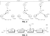
- Figure 2 is a diagram of an example two-way relaying scheme 200 that may combine multiple bit steams, for one BS 210 and two WTRUs 220a, 220b, using HM and broadcasting a network coded combined bit sequence to reduce the number of time slots for transmission.
- Three time slots may be used for each relaying cycle.
- a relaying cycle may begin when an RN broadcasts a beacon and end when the RN broadcasts a subsequent beacon.
- X AB may be used to describe the signal transmitted from node A to node B, and b AB as the bit sequence of signal X AB .
- time slot 1 the BS 210 and WTRU1 220a may transmit simultaneously to the RN 230.
- ML maximum-likelihood
- the BS 210 and WTRU2 220b may simultaneously transmit to the RN 230.
- SINR Signal to Interference plus Noise Ratios
- a modulation order generally higher than that for X nB and X Bn may be used for X R .
- X R may be transmitted using 16-QAM.
- b R 1 may be assigned to the LSB, and b R 2 may be assigned to the MSB, and vice versa.
- the RN 230 may broadcast X R to all parties, for example the BS 210, WTRU1 220a, and WTRU2 220b, by hierarchically modulating ( b R 1 , b R 2 ) or hierarchically modulating ( b R 2 , b R 1 ).
- b R 2 may be undecipherable to WTRU1 220a.
- b R 1 may be undecipherable to WTRU2 220b even if the SINR is acceptable for WTRU2 220b to decode it.
- the BS 210 and one WTRU may transmit to the RN 230 simultaneously.
- This direction is designated as DL, and it may involve the transmitters at the BS 210, WTRUs 220a, 220b, and the receiver at the RN 230.
- FIG. 3 is a diagram of an example WTRU1 transmitter 300.
- the transmitter 300 may comprise a CRC attachment unit 310, a channel encoding unit 320, a rate matching unit 330, a modulation unit 340, and an antenna 350.
- the transmitters in the BS and other WTRUs may be identical, except for the signal notations.
- the bit stream 360 destined to the BS from WTRU1 may be denoted as b 1 B , and the signal after modulation may be X 1 B . Note that it may be possible to select only a portion of the encoded bits to be transmitted, as specified by a Redundancy Version (RV) 370.
- RV Redundancy Version
- the CRC attachment unit 310 may receive a bit stream 360 and attach CRC bits to the bit stream 360.
- the bit stream 360 may be forwarded to the channel encoding unit 320 before being forwarded to the rate matching unit 330.
- the rate matching unit 330 may forward a coded bit sequence to the modulation unit 340.
- the modulation unit 340 may modulate the coded bit sequence and generate a packet X 1 B comprising of k symbols. Each symbol may be modulated, for example, using M-ary modulation.
- An example of a BS transmitter may be shown by modifying Figure 3 to replace the signal subscript 1B with B1 when transmitting to WTRU1, and B2 when transmitting to WTRU2, etc.
- An example of a WTRU2 transmitter may be shown by modifying Figure 3 to replace the signal subscript 1B with 2B.
- FIG. 4 is a diagram of a general structure of an RN receiver 400.
- the RN receiver 400 may include an ML detector 410, a Successive Interference Cancellation (SIC) detector (not shown), and/or any other detector that may enable the detection of multiple signals, one or more rate dematching/soft combining units 420, one or more channel decoding units 430, one or more CRC verification and removal units 440, an IBS generator 450, and an antenna 460.
- the downlink transmissions X B 1 and X 1 B from the BS and WTRU1 may be superimposed on each other and received by the RN as Y B 1 465.
- the RN may decode Y B 1 465 using the ML detector 410 to produce the soft bit estimate of c B 1 and c 1 B , denoted as ⁇ B 1 468 and ⁇ 1 B 469, which may be combined with those from one or more previous transmissions, if any, before being rate-dematched and decoded.
- the RN may generate estimates of two packets, and the corresponding bit sequences.
- a rate dematching/soft combining unit 420 and channel decoding unit 430 may then be applied to the corresponding bit sequences separately, and the resulting bit sequences, may be fed to the CRC verification and removal unit 440.
- the accumulated soft bits ê B 1 480 and ê 1 B 482 may also be preserved if the corresponding CRC is not valid.
- the first IBS may be generated and processed for transmission.
- the outputs from the RN may be an ACK/NACK B 1 470, an ACK/NACK 1 B 472, and an intermediate bit stream b R 1 474.
- the same transmitting and receiving processes may occur in the BS, WTRU2, and the RN.
- the RN may produce an ACK/NACK B 2 , an ACK/NACK 2 B , and intermediate bit stream b R 2 .
- the RN may combine bit streams b R 2 and b R 1 using the reference model illustrated in Figure 5 .
- the RN transmitter 500 may include one or more CRC attachment units 510, one or more channel encoding units 520, one or more rate matching units 530, an HM unit 540, and an antenna 550.
- the RN may broadcast the hierarchically modulated signal X R to the BS and all WTRUs.
- Hierarchical modulation may be applied in the RN transmitter at the HM unit 540.
- b R 2 and b R 1 may be coded into a combined constellation, at the channel encoding unit 520, such that the WTRU with the higher channel quality will have its data coded into the least significant bits (LSB)s of the constellation while the WTRU with the lower channel quality will have its data coded into the most significant bits (MSB)s.
- LSB least significant bits
- MSB most significant bits
- RVs may be selected for b R 2 and b R 1 independently.
- HM When retransmission is performed by the RN, HM may or may not be needed. In examples where a single packet, or paired packets ( b 1 B and b B 1 or b 2 B and b B 2 ), are received in error, only the intermediate bits b R 1 or b R 2 may be retransmitted. The chance for successful retransmission, therefore, may improve due to the absence of hierarchical transmission.
- CSR Control Signals at Relay
- the CSRs may serve as ACK/NACK signals for transmissions occurring in time slots 1 and 2, and RN operation status as well.
- the BS and WTRUs may demodulate the signals and process the information bits from the RN in time slot 3.
- the CSRs may be assumed to be received by the BS and WTRUs perfectly.
- CSR The definition of CSR is described in Table 1.
- Table 1 CSR [0] 0: b B 1 received unsuccessfully, 1: b B 1 received successfully; CSR [1] 0: b 1 B received unsuccessfully, 1: b 1 B received successfully; CSR [2] 0: b B 2 received unsuccessfully, 1: b B 2 received successfully; CSR [3] 0: b 2 B received unsuccessfully, 1: b 2 B received successfully; CSR [4] 1: Hierarchical modulation is applied if at least 1 packet in each time slot is successfully received and ⁇ 1,3 > ⁇ 2,3 , where ⁇ 1,3 and ⁇ 2,3 are the instantaneous received SINRs at WTRU1 and WTRU2, respectively. 0: No hierarchical modulation is applied.
- the RN may generate two intermediate bit sequences (IBS)s, b R 1 and b R 2 .
- IBS intermediate bit sequences
- b R 1 may be used as an example for illustration.
- HM may be 2M.
- QPSK QPSK
- 16-QAM 16-QAM will be adopted for hierarchical modulation.
- the RN may group g R, 3 l +1 and g R ,3 l +2 according to the instantaneous received SINRs at WTRU1 and WTRU2, ⁇ 1,3 and ⁇ 2,3 .
- the k th symbol, x R k may be determined by the bit sequence, b R , 1 kM ⁇ M + 1 , ... , b R , 1 kM , b R , 2 kM ⁇ M + 1 , ... , b R , 2 kM if ⁇ 1,3 ⁇ ⁇ 2,3 , or b R , 2 kM ⁇ M + 1 , ... , b R , 2 kM , b R , 1 kM ⁇ M + 1 , ... , b R , 1 kM if ⁇ 1,3 ⁇ ⁇ 2,3 .
- the grouping may be performed such that a sequence with a low SINR may be easily modulated.
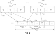
- the RN may apply HM based on an SNR level.
- the RN may group the IBSs based on an SINR level.
- IBS [1] 610 may have the lowest SINR 620 and IBS [N] 630 may have the highest SINR 640.
- the RN may generate an IBS R 650 for broadcast by arranging the received bits from IBS [1] ...IBS [N] into symbols.
- the RN may use the first bit 662 of IBS [1] for the first bit 664 in symbol 1 660 and the first bit 666 in IBS [N] for the last bit 668 in symbol 1 660.
- the RN may use the second bit 672 of IBS [1] for the first bit 674 in symbol 2 670 and the second bit 676 of IBS [N] for the last bit 678 in symbol 2 670.
- FIG. 7 is a diagram of an example BS receiver 700.
- the BS receiver may include an HM detector 710, one or more rate dematching/soft combining units 720, one or more channel decoding units 730, one or more CRC verification and removal units 740, one or more IBS generators 750, and an antenna 760.
- the HM detector 710 may estimate corresponding bit sequences, and apply them to a rate dematching/soft combining unit 720 and channel decoding unit 730 separately.
- the resulting bit sequences may be fed to the CRC verification and removal unit 740.
- the CRC verification and removal unit 740 may be configured to generate an ACK/NACK 770 that may be transmitted to one or more WTRUs via an RN.
- the IBS generators 750 may generate corresponding IBSs process them for transmission.
- the BS may decode the entire hierarchically modulated signal from the RN broadcast and extract b R 1 and b R 2 . By performing an XOR operation on one or more previously transmitted bit streams, the BS may decode the bit streams intended for it. The output of the XOR operation between the received bits and the bits it transmitted may be the bit stream intended for the BS. If the bit stream was not received successfully by the RN, as indicated by an NACK from the RN, all zero bits or a pseudo random bit sequence may be used in the XOR operation. The BS may not know whether a particular downlink transmission had been successful if an ACK or a NACK is not received for any downlink transmission. In this scenario, the BS may blindly decode for both cases, and may deem whichever yields a valid CRC to be the desired data packet.
- FIG. 8 is a diagram of a general structure of a WTRU receiver 800.
- the WTRU receiver 800 may include an HM detector 810, a rate dematching/soft combining unit 820, a channel decoding unit 830, a CRC verification and removal unit 840, an IBS generator 850, and an antenna 860.
- the HM detector 810 may estimate corresponding bit sequences, and apply them to a rate dematching/soft combining unit 820 and channel decoding unit 830.
- the resulting bit sequences may be fed to the CRC verification and removal unit 840.
- the CRC verification and removal unit 840 may be configured to generate an ACK/NACK 870 that may be transmitted to the BS via an RN.
- the IBS generator 850 may generate an IBS and process it for transmission.
- Bit streams from the hierarchically modulated RN broadcast may be decoded by the WTRUs to which each of the bit streams may be intended.
- WTRU1 may only need to decode b R 1
- WTRU2 may only need to decode b R 2 .
- the WTRU may decode the bits intended for it. If its downlink bit stream was received successfully by the RN, as may be indicated by a NACK from the RN, all zero bits or a pseudo random bit sequence may be used in the XOR operation.
- the WTRU may not know whether its downlink transmission had been successful if an ACK or a NACK is not received. In this scenario, the WTRU may blindly decode for both cases, and may deem whichever yields a valid CRC to be the desired data packet.
- the WTRU 1 may process y 1,3 and generate b B 1 .
- the BS and WTRU2 may remain idle.
- CSR [00100]
- WTRU2 may process y 2,3 and generate b B 2 .
- the BS and WTRU1 may remain idle.
- CSR [00010] or [01000]
- the BS may process y B ,3 and generate b 1 B or b 2 B .
- WTRU1 and WTRU2 may remain idle.
- the BS may process y B, 3 and generate b 1 B by XOR ( b B 1 , b ⁇ R 1 ), WTRU1 may process y 1,3 and generate b B 1 by XOR ( b 1 B , b ⁇ R 2 ), and WTRU2 may remain idle.
- the receiver 700 may be configured for full demodulation in a double stream scenario.
- the receiver 800 may be configured for partial demodulation in a double stream scenario, where the HM detector 810 may be configured to only determine the quadrant of received signals.
- the WTRU with a larger instantaneous SINR may adopt the receiver structure depicted in Figure 7 .
- the WTRU with the smaller instantaneous SINR may adopt the receiver structure as depicted in Figure 8 .
- the BS may process y B ,3 and generate b 2 B by XOR ( b B 2 , b ⁇ R 2 ).
- WTRU2 may process y 2,3 and generate b B 2 by XOR ( b 2 B , b ⁇ R 2 ), and WTRU1 may remain idle.
- CSR [x0101]
- WTRU1 may determine the quadrant of y 1,3 and generate b B 1
- WTRU2 may demodulate y 2,3 and generate b B 2 .
- CSR [4] 1
- WTRU2 may determine the quadrant of y 2,3 and generate b B 2
- WTRU1 may demodulate y 1,3 and generate b B 1
- the BS may remain idle.
- the BS may demodulate y B ,3 and generate b 1 B and b 2 B .
- WTRU1 and WTRU2 may remain idle.
- the WTRU1 may then generate b B 1 by XOR(b 1 B , b ⁇ R ,1 ) .
- the BS then may generate b 1 B by XOR ( b B 1 , b ⁇ R ,1 ).
- the BS may demodulate y B,3 and generate b ⁇ R, 1 and b 2 B .
- the BS may generate b 1 B by XOR(b B 1 , b ⁇ R ,1 ), and WTRU2 may remain idle.
- the WTRU2 then may generate b B 2 by XOR(b 2 B , b ⁇ R ,2 ) .
- the BS may generate b 2 B by XOR ( b B 2 , b ⁇ R ,2 ).
- the BS may demodulate y B ,3 and generate b ⁇ R ,2 and b 1 B .
- the BS may generate b 2 B by XOR ( b B 2 , b ⁇ R ,2 ), and WTRU1 may remain idle.
- the BS may demodulate y B ,3 and generate b ⁇ R ,1 and b ⁇ R ,2 .
- the BS may generate b 1 B by XOR(b B 1 , b ⁇ R ,1 ), and b 2 B by XOR ( b B 2 , b ⁇ R ,2 ).
- User pairing may be performed by either applying Random Pairing or Pairing by Ordering.
- Random Pairing two WTRUs may be randomly selected from N WTRUs to perform the HM scheme. The random pairing may continue until all WTRUs are selected.
- the user pairing by ordering may be described as follows.
- Index [i] may be used to denote the sorted version of SINRs.
- WTRU [i] may denote the WTRU with the i th largest SINR.
- the RN receiver may have SIC or ML detection capability to enable decoding of distinct data received simultaneously.
- Each node may be equipped with a single antenna. All communication links may be allocated to a single carrier frequency in TDD fashion (i.e., the channels between node pairs may be reciprocal). The same modulation scheme and coded packet size may be used at the BS and the WTRUs.
- the message exchange in the N WTRU example may be performed in two phases, a MAC phase and broadcast (BC) phase.
- the MAC phase may consists of N time slots.
- the WTRU i may transmit coded data packets for the BS to the RN simultaneously.
- the RN may use SIC or ML to recover the messages of the BS and WTRU i .
- the RN may perform an XOR operation on both messages, and generate a new data bit sequence, denoted, for example, by the i th intermediate bit sequence, IBS i .
- N different IBS may be generated by the RN at the end of the N time slots, and the RN may begin the BC phase.
- the RN may transmit the N IBSs in one time slot using a modulation scheme with an N- times larger constellation size.
- the RN may use HM and opportunistically exploit the differing channel qualities for each destination node by ordering the layers of the HM.
- Two benefits may be achieved by using HM in this way.
- HM may not only enable carrying multiple IBSs simultaneously, it may also protect data destined for the WTRUs with poorer channel conditions by mapping their data to lower data rates.
- Some channel quality information may be known at the RN to enable the implementation of HM in this way.
- Various parameters may be used to support this, such as the channel quality indicator (CQI) or WTRU instantaneous SNR, for example.
- CQI channel quality indicator
- WTRU instantaneous SNR for example.
- the N IBSs generated at the end of the MAC phase may be grouped together to create a new intermediate bit sequence (IBS R ) at the RN for the purpose of HM transmission in the BC phase.
- IBS R intermediate bit sequence
- the RN may order the SNRs of N RN-to-WTRU channels in an ascending order, such that SNR [i] ⁇ SNR [2] ⁇ ... ⁇ SNR [N] .
- IBS [i] may denote a bit sequence associated to the RN-to-WTRU channel with SNR [i] .
- the bits of each sequence IBS [i] may be rearranged at the RN into Q symbols, where Q is the sequence length of each of the IBSs.
- Each symbol may consist of N bits drawn from the N IBS sequences, such that the k th bit of each sequence may be in the k th symbol.
- the bits of each symbol may be ordered the same as their corresponding SNR.
- the BS may demodulate and decode the received signal and, assuming successful decoding, it may dismantle IBS R to recover all of the N original IBSs. The BS may then perform an XOR operation on the i th IBS, with its own data transmitted in the same time slot, to retrieve the message intended for WTRU i .
- the WTRUs may demodulate and decode the received signal partially or fully depending on the order of their IBSs. Assuming successful decoding, WTRU i may only perform an XOR operation on the i th IBS, with its own data, to retrieve the BS message for WTRU i .
- the general two-way relaying schemes described above may implement a HARQ process.
- HARQ is a form of implicit link adaptation and may improve the overall throughput in wireless communications.
- the HARQ design for the two-way relaying scheme may use physical-layer network coding.
- the example embodiments described herein may enable each BS or WTRU to know whether the data it transmits has reached the end destination. Since each data packet may go over two hops through the RN, an ACK on each link may not necessarily imply that the data has reached the destination.
- the example embodiments may employ a retransmission strategy so that the efficiency of the relaying scheme is not severely or unnecessarily impaired when a single transmission fails. These embodiments may also apply HARQ and other link adaptation techniques to the relaying scheme. Since the RN broadcasts XOR'ed data, a determination may be performed on how to decode the broadcast if any downlink data packet is received in error.
- the proposed design may involve elements in a wireless communication device and system that may be considered to be the PHY and MAC layers.
- the RN may be in control of the relaying operation, responsible for scheduling the BS and WTRUs for their time slots for transmission and reception.
- Each physical link may be treated as an independent wireless link employing HARQ.
- the ACKs and NACKs across the two hops may be combined into a destination ACK/NACK so that source and destination, for example the RLC, are informed of the overall relay link success or failure.
- Unsuccessful DL transmissions may not be retransmitted until the next relaying cycle, such that they do not interrupt the relaying cycle.
- Any unsuccessful UL transmission (broadcast by the RN), however, may trigger the RN to retransmit the broadcast, thereby extending the relaying cycle.
- the modulation for the retransmission may change depending on the NACK(s) received.
- the example two-way relaying schemes described herein may use a stop-and-wait HARQ process.
- Acknowledgements over individual links may be transmitted over a control channel which is orthogonal with, or independent of, the data channel. Acknowledgements may not be perfectly reliable.
- a beacon may be transmitted by the RN to indicate the start of the relay cycle and to inform each party of their time slots to transmit and receive. Alternatively, a beacon may be transmitted periodically at every slot.
- a special beacon may contain an indicator, and may be transmitted at the beginning of the first slot to indicate the beginning of each relaying cycle.
- the HARQ of the two-way relay scheme using network coding may be characterized by the following examples.
- the RN may send a NACK to the sender, which could be either a BS or WTRU.
- the RN may use zero to represent failed-to-receive bits in network coding (XOR). XOR with all zeroes may keep the bits unchanged.
- XOR network coding
- a pseudo random bit stream previously agreed upon between the transmitter and receiver, may be used to preserve data privacy.
- the transmitting node of the link for example the BS or the WTRU, may assume all-zero bits or a previously agreed upon pseudo random bit stream.
- the transmitting node of the link may decode the network coding in the RN broadcast with all zeroes or the pseudo random bits. If neither an ACK nor a NACK is received, the transmitting node of the link, without knowing whether its downlink has been correctly received by the RN, may blindly decode the RN broadcast by XORing with either its downlink data, a zero, or pseudo random bits. Whichever option results in a valid CRC may be used to decode the desired data.
- the RN may decide not to use hierarchical modulation at all in the broadcast phase. In this example, the RN may inform these two nodes of the modulation used for the broadcast.
- an RN may not wait for a DL failure. Unsuccessfully transmitted data may be retransmitted in the next relaying cycle. In the case of multiple pipelined HARQ processes, the retransmission may be scheduled for the next available opportunity.
- the RN may retransmit the broadcast, thereby extending the relaying cycle.
- the relaying cycle may be extended until all ACKs are received or until the retransmission times out.
- the retransmission may not necessarily transmit the same X R signal. Instead, hierarchical modulation may be modified to transmit X' R , that may contain only the necessary bit streams, as discussed below.
- Hierarchical modulation in the retransmission may be applied when the unpaired bit streams are received in error.
- the intermediate bits b R 1 , b R 2 may be retransmitted.
- the original bit streams b 1 B , b B 1 , b 2 B or b B 2 may not be retransmitted.
- the 2 nd and subsequent retransmissions may transmit the same intermediate bits or hierarchical modulation as the 1 st retransmission. This may be performed to preserve data privacy at the link level without sacrificing performance. For example, the number of bits to be transmitted may be the same, and only the intended recipients may decode them.
- transmitting the same intermediate bits or hierarchical modulation as the 1 st transmission may allow for soft combining of retransmissions.
- the format of retransmissions may be communicated to the intended recipient through control channels.
- soft combining and redundancy versions may be used.
- any retransmission may be combined with one or more previous transmissions to improve the chance for decoding success.
- Chase combining for example, all the encoded bits may be transmitted at each retransmission.
- incremental redundancy for example, as a form of implicit link adaptation, different encoded bits may be transmitted at each retransmission.
- the systematic bits (S) may be transmitted the first time, the first parity bits (P1) the 2 nd time, and the second parity bits (P2) the 3 rd time, etc.
- Each set of bits transmitted may be designated a redundancy version (RV).
- the receiver may request a specific set of bits to be retransmitted based on measurements, such as SINR. This approach may require more acknowledgement overhead.
- modulation order may be used as a form of explicit link adaptation. It may be possible to change the coding rate and therefore modulation order for one or more retransmissions. Changing the modulation order may require all parties involved to be informed. For the downlink, only the RN may need to know of the change. For the uplink, all receivers may need to be informed of the change.
- Hierarchical demodulation at the BS or WTRU may not be needed if the RN does not need to use hierarchical modulation.
- the receiver may use one indicator bit through the control channel whether a different modulation is expected.
- the BS and the WTRU may use 4QAM, and the RN may use 16QAM with HM.
- the RN may use 4QAM without HM for a retransmission, or it may use another modulation that is different than 16QAM with HM.
- the change in modulation may be indicated by the RN.
- the BS and WTRUs may maintain their soft bit buffers if the CRC is not valid.
- beacon transmitted by the RN to indicate the start of the relaying cycle.
- the beacon may also contain instructions to the BS and WTRUs about their assignment of times slots for transmission and reception.
- a beacon may be transmitted to indicate the beginning of every time slot, and that a special beacon, containing an indicator, may be transmitted at the beginning of the first time slot in each relaying cycle to serve the above-mentioned purposes.
- Per-link acknowledgements may be transmitted over control channels that are orthogonal to the data traffic channels. Acknowledgements may be perfectly reliable. For example, they may always be received successfully with no missing ACKs or NACKs. In other words, a transmitter may always know whether its data has been successfully decoded by the receiver. Knowing whether the data has been successfully decoded by the receiver may be necessary in order for the network-coded transmissions to be decoded correctly.
- a mechanism for implementing a destination-ACK and a destination-NACK may be used for transmission over relays.
- the destination-ACK and destination-NACK may be used to confirmation whether a data packet has successfully arrived at the receiving end of the second hop.
- This information may be provided to the upper layers, for example, the radio link controller (RLC) layer of the transmitting node.
- the transmitting node may receive an acknowledgement from the RN to indicate whether the first hop packet has arrived at the RN.
- the transmitting node may only know whether the packet has arrived at the receiving end of the second hop after receiving a destination-ACK or destination-NACK.
- a destination-ACK may be transmitted by the RN after its broadcast transmission has been acknowledged by the destination.
- a destination-NACK may be transmitted by the RN after its broadcast transmission has failed to reach the destination at least once and has timed out.
- DL transmission failures from the BS to the RN and from the WTRU to the RN may not interrupt the relay cycle.
- a DL error occurs, as indicated by a NACK from the RN
- a retransmission may be performed in the next relay cycle.
- the RN may assume all zero bits are received and use all zeroes in the network coding by performing an XOR operation with all zeroes and keeping the bit stream unchanged.
- the corresponding DL transmitter may decode the RN broadcast based on that assumption.
- the received soft bits may be preserved for combining with one or more subsequent retransmissions.
- the two parties may use a previously agreed pseudo random bit sequence. If only the two parties involved area aware of what this random sequence is, data privacy may be preserved in the case of DL transmission failure.
- Any UL transmission failure may trigger a retransmission by the RN in the immediate next time slot, thereby extending the relaying cycle by one time slot for each retransmission.
- the retransmission may or may not transmit the hierarchically modulated bit stream based on one or more UL transmission failures. As long as the intermediate bit stream remains the same for retransmissions, it may be possible to perform soft combining. For both DL and UL, a retransmission may time out if the number of transmissions has exceeded some predefined constant, and the DL and UL may have different time-outs.
- the transmitter may have several choices in selecting the encoded bits to transmit.
- the soft combining may be performed through puncturing.
- the transmitter may also change the modulation and coding scheme (MCS) for each particular transmission or retransmission.
- MCS modulation and coding scheme
- the RV used in the HARQ process may include both puncturing and MCS.
- Soft combining may be used in HARQ.
- conventional ARQ when a block error occurs, the decoded bits may be discarded, and the information may be retransmitted until all the bits are received and decoded correctly.
- the errored bits may not be discarded, but rather their soft bits may be combined with those from one or more subsequent retransmissions, thereby improving the chances of correct decoding.
- Soft combining There are two basic forms of soft combining: Chase combining and incremental redundancy. The actual combining method used in relay scenarios may be some combination of both forms.
- Soft combining may be part of rate dematching, where the received soft bits may be matched with what the channel decoder expects.
- the rate dematcher may fill the void with a neutral soft value.
- some form of combining may be needed.
- the following example illustrates a mechanism for soft combining using the WTRU1 transmitter from Figure 3 and the RN receiver from Figure 4 .
- data may be encoded through FEC.
- the transmitter may choose to transmit c 1 B i , which may be a subset of e 1 B .
- the choice of the subset may be based on Chase combining incremental redundancy considerations.
- Y B 1 i p e 1 B k 0
- Y B 1 i , for k 1 , 2 , 3 , ... , N .
- LLR log likelihood ratio
- the LLR value for a neutral bit may be 0, such that there is an equal likelihood the bit transmitted was 0 or 1.
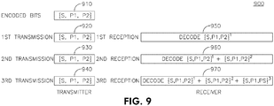
- Figure 9 is a diagram of an example mechanism 900 for Chase combining.
- the encoded bits 910 may be partitioned into S bits, P1 bits, and P2 bits. All the encoded bits 910 may be transmitted in a first transmission 920, a second transmission 930, and a third transmission 940.
- the receiver may be configured to receive the soft bits, sum the soft bits, and channel-decode the soft bits. For example, in the first reception 950, the receiver may decode ⁇ S, P1, P2 ⁇ 1 . In the second reception 960, the receiver may decode ⁇ S, P1, P2 ⁇ 1 + ⁇ S, P1, P2 ⁇ 2 .
- the receiver may decode ⁇ S, P1, P2 ⁇ 1 + ⁇ S, P1, P2 ⁇ 2 + ⁇ S, P1, P2 ⁇ 3 .
- the soft bits may become increasingly reliable, and the chance for successful decoding may be improved.
- Chase combining may also be used in retransmission.
- Figure 10 is a diagram of an example incremental redundancy mechanism 1000.
- the encoded bits may be partitioned into S bits 1010, P1 bits 1020, and P2 bits 1030.
- the transmitter 1040 may transmit the S bits 1010 in a first transmission 1015, the P1 bits 1020 in a second transmission 1025, and the P2 bits 1030 in a third transmission 1035.
- the receiver 1050 may receive and decode ⁇ S 1 ⁇ 1060 in the first reception 1065, ⁇ S 1 , P1 2 ⁇ 1070 in the second reception 1075, and ⁇ S 1 , P1 2 , P2 3 ⁇ 1080 in the third reception 1085.
- a second transmission may be requested.
- a 3 rd transmission may be requested.
- the transmitter may only transmit a portion of the FEC-encoded bits in each time slot. If the receiver is able to successfully decode the FEC-encoded bits, additional transmissions may not be needed. If the receiver fails to decode the data correctly the first time, additional encoded bits may be transmitted to provide the receiver additional information for decoding. For turbo coding, incremental redundancy, as a form of implicit channel adaptation, may achieve higher spectral efficiency than Chase combining.
- the RVs may not be partitioned exactly along the lines of systematic and parity bits. Including some parity bits in the systematic RV and having some systematic bits in the parity RVs may improve performance.
- the number of transmissions may exceed 3, in which case there may be more than 3 RVs, or certain RVs may be reused in retransmissions.
- the number of coded bits in each transmission may not be the same as in the previous transmissions. This may not be an issue with network coding, as only the hard bits, those decoded from the coded bits, may be involved in the XOR operation.
- a HARQ may use a retransmission strategy that is somewhere between Chase combining and incremental redundancy. Since a retransmission may be based on the ACK/NACK received by the transmitter, the particular soft combining method may be selected regardless of how the acknowledgement scheme is designed. For example, the soft combining method may be selected regardless of the acknowledgement scheme as long as the soft bits may be combined and the transmitters and receivers involved are following the same protocol.
- State machines are actions that may be performed on each node based on the input each node receives.
- Each node may act independently and have no direct control or knowledge on the state of, or actions by, other nodes, other than the input it may receive and an assumption that other nodes are following the protocol.
- HARQ actions may be performed in the PHY and MAC layers.
- the state machines for the BS and WTRUs are similar, but not identical, since the BS may transmit in every downlink time slot while each WTRU may transmit in only one, or not all, of the downlink slots.
- Example state machines for WTRU1 and the BS are illustrated in Figures 11 and 13 , respectively.
- the state machines for other WTRUs may be analogous to that of WTRU1.
- WTRU1 may blindly decode b B 1 by setting u 1 B ( i ) to: b 1 B ( i ), zero, or a pseudo random bit sequence for preserving data privacy. WTRU1 may base its decoding strategy on whichever case yields a valid CRC that results in the desired b B 1 .
- the BS may employ the same blind process in XOR decoding.
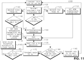
- FIG 11 is a flow diagram of an example HARQ state machine 1100 for a WTRU.
- a WTRU may transmit 1105 data for a BS via an RN.
- the WTRU may also transmit 1110 and ACK/NACK for a previous transmission block (TB).
- TB transmission block
- the WTRU may receive 1120 an ACK from the RN and set 1125 a new transmission parameter.
- the new transmission parameter may be set based on a channel condition of each of the involved links and may involve new data.
- the WTRU may end transmission 1130 and wait 1135 for an RN broadcast.
- the WTRU may receive 1140 a NACK from the RN. If a retransmission has not timed out 1145, the WTRU may set 1150 a retransmission parameter, end transmission 1130, and wait 1135 for an RN broadcast. If a retransmission has timed out 1145, the WTRU may set 1155 new transmission parameters and indicate a NACK to higher layers, end transmission 1130, and wait 1135 for an RN broadcast.
- the WTRU may determine 1160 whether the RN broadcast includes a valid CRC. If the RN broadcast includes a valid CRC, the WTRU may transmit 1165 an ACK to the relay and recover its intended data. If the RN broadcast does not include a valid CRC, the WTRU may transmit 1170 a NACK to the RN. If the reception has not timed out 1175, the WTRU may wait 1135 for an RN broadcast. If the reception has timed out 1175, the WTRU may send 1180 a failed reception indication to higher layers and return to transmitting data 1105.
- FIG. 12 is a flow diagram of an example HARQ state machine 1200 for a BS.
- the BS may transmit 1205 data for a WTRU via an RN.
- the BS may transmit 1210 an ACK/NACK for a previous TB. If a link to the RN is successfully established 1215, the BS may receive 1220 an ACK from the RN and set 1225 a new transmission parameter.
- the new transmission parameter may be set based on a channel condition and may include new data.
- the BS may determine 1230 whether there are additional WTRUs awaiting transmission. If there are additional WTRUs awaiting transmission, the BS may resume transmitting data 1205. If there are no WTRUs awaiting transmission, the BS may wait 1260 for an RN broadcast.
- the BS may receive 1240 a NACK from the RN. If a retransmission has not timed out 1245, the BS may set 1250 a retransmission parameter, and determine 1230 whether there are additional WTRUs awaiting transmission. If a retransmission has timed out 1245, the BS may set 1255 new transmission parameters and indicate a NACK to higher layers, and determine 1230 whether there are additional WTRUs awaiting transmission. The new transmission parameters may include the same data, or it may include different data. If there are additional WTRUs awaiting transmission, the BS may resume transmitting data 1205. If there are no WTRUs awaiting transmission, the BS may wait 1260 for an RN broadcast.
- the WTRU may determine 1265 whether the RN broadcast includes a valid CRC. If the RN broadcast includes a valid CRC, the BS may transmit 1270 an ACK to the relay and recovers its data. If the RN broadcast does not include a valid CRC, the BS may transmit 1275 a NACK to the RN. If the reception has not timed out 1280, the BS may wait 1260 for an RN broadcast. If the reception has timed out 1280, the BS may send 1285 a failed reception indication to higher layers and return to transmitting data 1205.
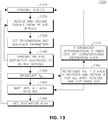
- Figure 13 is a flow diagram of an example HARQ state machine 1300 for an RN.
- the RN may transmit 1310 a beacon and receive and decode 1320 signals from a BS and one or more WTRUs.
- the RN may then set 1330 transmission and ACK/NACK parameters, and transmit 1340 RN and destination ACK/NACKs to the BS and one or more WTRUs.
- the RN may wait to receive all the signals from the BS and one or more WTRUs before broadcasting 1350 X R data.
- the RN may retransmit the data X' R and repeat if not all ACKs are received and the broadcast retransmission is not timed out. If the broadcast retransmission is timed out 1370, the RN may set the corresponding destination NACKs and resume transmitting 1310 the beacon. When all the ACKs are received 1380, the RN may set 1390 the destination ACKs and resume transmitting 1310 the beacon.
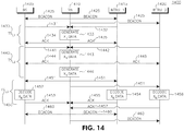
- FIG 14 is a signal diagram 1400 of an example two-way relay transmission where all downlink and uplink transmissions are successful.
- This example relay scheme may involve a BS 1405, an RN 1410, a first WTRU (WTRU1) 1415, and a second WTRU (WTRU2) 1420, where the RN 1410 may transmit a beacon 1425.
- WTRU1 WTRU
- WTRU2 WTRU2
- the RN 1410 may receive a signal 1431 from the BS 1405 and a signal 1432 from WTRU1 1415. The RN 1410 may receive these signals simultaneously. The RN 1410 may then generate X R data 1433 and transmit an ACK 1434 to the BS 1405 and an ACK 1435 to WTRU1 1415.
- the RN may adopt a transmitter structure, as shown in Figure 5 , to generate the X R data 1433.
- the RN 1410 may receive a signal 1441 from the BS 1405 and a signal 1442 from WTRU2 1420. The RN 1410 may receive these signals simultaneously. The RN 1410 may then generate X R data 1443 and transmit an ACK 1444 to the BS 1405 and an ACK 1445 to WTRU2 1420. The RN 1410 may then generate X R data 1446.
- the RN 1410 may broadcast X R data 1451.
- the BS 1405 may decode 1452 a portion of the X R data 1451 that was intended for the BS 1405 and transmit an ACK 1453 to the RN 1410.
- WTRU1 1415 may decode 1454 a portion of the X R data 1451 that was intended for WTRU1 1415 and transmit an ACK 1455 to the RN 1410.
- WTRU2 1420 may decode 1456 a portion of the X R data 1451 that was intended for WTRU2 1420 and transmit an ACK 1457 to the RN 1410.
- the RN 1410 may transmit a beacon 1460.
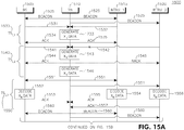
- Figures 15a and 15b are a signal diagram 1500 of an example two-way relay transmission where one downlink transmission fails.
- This example relay scheme may involve a BS 1505, an RN 1510, a first WTRU (WTRU1) 1515, and a second WTRU (WTRU2) 1520, where the RN 1510 may transmit a beacon 1525.
- WTRU1 WTRU
- WTRU2 WTRU2
- the RN 1510 may receive a signal 1531 from the BS 1505 and a signal 1532 from WTRU1 1515.
- the RN 1510 may receive these signals simultaneously.
- the RN 1510 may then generate X R data 1533 and transmit an ACK 1534 to the BS 1505 and an ACK 1535 to WTRU1 1515.
- the RN may adopt a transmitter structure, as shown in Figure 5 , to generate the X R data 1533.
- the RN 1510 may receive a signal 1541 from the BS 1505, however a signal 1542 from WTRU2 1520 may not be received. The RN 1510 may then generate X R data 1543 and transmit an ACK 1544 to the BS 1505 and an NACK 1545 to WTRU2 1520. The RN 1510 may then generate X R data 1546.
- the RN 1510 may broadcast X R data 1551.
- the BS 1505 may decode 1552 a portion of the X R data 1551 that was intended for the BS 1505 and transmit an ACK 1553 to the RN 1510.
- WTRU1 1515 may decode 1554 a portion of the X R data 1551 that was intended for WTRU1 1515 and transmit an ACK 1555 to the RN 1510.
- WTRU2 1520 may decode 1556 a portion of the X R data 1551 that was intended for WTRU2 1520 and transmit an ACK 1557 to the RN 1510. Once all the ACKs are received, the RN 1510 may transmit a beacon 1560.
- the RN 1510 may receive a signal 1571 from the BS 1505 and a signal 1572 from WTRU1 1515.
- the RN 1510 may receive these signals simultaneously.
- the RN 1510 may then generate X R data 1573 and transmit an ACK 1574 to the BS 1505 and an ACK 1575 to WTRU1 1515.
- the RN 1510 may receive a signal 1581 from the BS 1505 and a retransmission signal 1582 from WTRU2 1520. These signals may be received simultaneously. The RN 1510 may then generate X R data 1583 and transmit an ACK 1584 to the BS 1505 and an ACK 1585 to WTRU2 1520. The RN 1510 may then generate X R data 1586.
- the RN 1510 may broadcast X R data 1591.
- the BS 1505 may decode 1592 a portion of the X R data 1591 that was intended for the BS 1505 and transmit an ACK 1593 to the RN 1510.
- WTRU1 1515 may decode 1594 a portion of the X R data 1591 that was intended for WTRU1 1515 and transmit an ACK 1595 to the RN 1510.
- WTRU2 1520 may decode 1596 a portion of the X R data 1591 that was intended for WTRU2 1520 and transmit an ACK 1597 to the RN 1510. Once all the ACKs are received, the RN 1510 may transmit a beacon 1598.
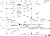
- FIG 16 is a signal diagram 1600 of an example two-way relay transmission where one uplink transmission fails.
- This example relay scheme may involve a BS 1605, an RN 1610, a first WTRU (WTRU1) 1615, and a second WTRU (WTRU2) 1620, where the RN 1610 may transmit a beacon 1625.
- WTRU1 WTRU
- WTRU2 WTRU2
- the RN 1610 may receive a signal 1631 from the BS 1605 and a signal 1632 from WTRU1 1615. The RN 1610 may receive these signals simultaneously. The RN 1610 may then generate X R data 1633 and transmit an ACK 1634 to the BS 1605 and an ACK 1635 to WTRU1 1615.
- the RN 1610 may receive a signal 1641 from the BS 1605 and a signal 1642 from WTRU2 1620. The RN 1610 may receive these signals simultaneously. The RN 1610 may then generate X R data 1643 and transmit an ACK 1644 to the BS 1605 and an ACK 1645 to WTRU2 1620. The RN 1610 may then generate X R data 1646.
- the RN 1610 may broadcast X R data 1651.
- the BS 1605 may not receive X R data 1651, and may decode 1652 in error and transmit a NACK 1653 to the RN 1610.
- WTRU1 1615 may decode 1654 a portion of the X R data 1651 that was intended for WTRU1 1615 and transmit an ACK 1655 to the RN 1610.
- WTRU2 1620 may decode 1656 a portion of the X R data 1651 that was intended for WTRU2 1620 and transmit an ACK 1657 to the RN 1610.
- the RN 1610 may broadcast a retransmission of the X R data 1661.
- the BS 1605 may decode the retransmitted X R data 1661 and transmit and ACK 1663 to the RN 1610.
- WTRU1 1615 may take no action 1664 and wait for a beacon 1670 transmission from the RN 1610.
- WTRU2 1620 may take no action 1666 and wait for a beacon 1670 transmission from the RN 1610.
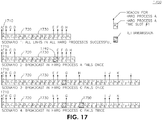
- acknowledgements may be immediately available before the next time slot, and retransmissions may be scheduled for predetermined, in some cases immediately next, time slots.
- retransmission opportunities and ACK/NACKs may only become available after several time slots due to processing delay.
- ACK/NACKs may become available after a fixed number of time slots, and retransmission opportunities may be scheduled a fixed number of time slots later. This may be an efficient mode of operation since there is no need to attach an address or process ID to the acknowledgement and retransmission, and that the receivers may know when to expect data. Multiple relaying cycles and their HARQ processes may be pipelined to accommodate the number of slots needed for acknowledgements and retransmission.
- Each relaying cycle may include 3 time slots, for example, A 1 1710, A 2 1720, and A 3 1730, and each uplink retransmission may extend the cycle with another time slot, for example, A 4 1740, C 5 1750, etc.
- the proposed HARQ scheme may also be applied in asynchronous applications.
- acknowledgement or retransmission may not arrive at expected RTT time slots.
- the receiver may continuously monitor the data and the messages, or the data may have a process ID attached to them.
- Table 3 summarizes the information related to HARQ that may be carried in the control channels. Some of the information may be carried in the beacon for RN. Table 3.
- the network coding scheme may assume that the data packets from all nodes are of the same size in order to perform the XOR operation.
- the payload data may be padded with dummy bits to form data packets of identical size.
- the redundant bits from a Reed-Solomon encoder may be used as the padding bits.
- Such a design may utilize the extra coding gain of a Reed-Solomon code to achieve better reliability for the payload data.
- the data packet may be recovered for use in the XOR network coding as long as the payload data can be correctly decoded.
- ROM read only memory
- RAM random access memory
- register cache memory
- semiconductor memory devices magnetic media such as internal hard disks and removable disks, magneto-optical media, and optical media such as CD-ROM disks, and digital versatile disks (DVDs).
- a processor in association with software may be used to implement a radio frequency transceiver for use in a WTRU, UE, terminal, base station, RNC, or any host computer.
Applications Claiming Priority (2)
| Application Number | Priority Date | Filing Date | Title |
|---|---|---|---|
| US25417809P | 2009-10-22 | 2009-10-22 | |
| PCT/US2010/053819 WO2011050301A2 (en) | 2009-10-22 | 2010-10-22 | Method and apparatus for a two-way relaying scheme with physical layer network coding |
Publications (2)
| Publication Number | Publication Date |
|---|---|
| EP2491757A2 EP2491757A2 (en) | 2012-08-29 |
| EP2491757B1 true EP2491757B1 (en) | 2016-12-14 |
Family
ID=43770543
Family Applications (1)
| Application Number | Title | Priority Date | Filing Date |
|---|---|---|---|
| EP10775991.2A Not-in-force EP2491757B1 (en) | 2009-10-22 | 2010-10-22 | Method and apparatus for a two-way relaying scheme with physical layer network coding |
Country Status (6)
| Country | Link |
|---|---|
| US (1) | US8908624B2 (ko) |
| EP (1) | EP2491757B1 (ko) |
| JP (2) | JP5519798B2 (ko) |
| KR (1) | KR101753926B1 (ko) |
| CN (1) | CN102907169B (ko) |
| WO (1) | WO2011050301A2 (ko) |
Families Citing this family (52)
| Publication number | Priority date | Publication date | Assignee | Title |
|---|---|---|---|---|
| CN102792727B (zh) * | 2010-01-20 | 2016-05-25 | 诺基亚技术有限公司 | 在多无线电接入环境中提供上行链路控制信令的方法和设备 |
| EP2533468B1 (en) * | 2010-02-05 | 2019-04-10 | Electronics And Telecommunications Research Institute | Communication method among a source device, a destination device and a relay device |
| WO2011119909A1 (en) | 2010-03-25 | 2011-09-29 | Massachusetts Institute Of Technology | Secure network coding for multi-resolution wireless video streaming |
| US10530574B2 (en) | 2010-03-25 | 2020-01-07 | Massachusetts Institute Of Technology | Secure network coding for multi-description wireless transmission |
| WO2013006697A2 (en) | 2011-07-05 | 2013-01-10 | Massachusetts Institute Of Technology | Energy-efficient time-stampless adaptive nonuniform sampling |
| US9143274B2 (en) | 2011-10-31 | 2015-09-22 | Massachusetts Institute Of Technology | Traffic backfilling via network coding in a multi-packet reception network |
| ES2884092T3 (es) | 2011-11-05 | 2021-12-10 | Massachusetts Inst Technology | Método y aparato para una transmisión eficaz de información a múltiples nodos |
| US8780693B2 (en) | 2011-11-08 | 2014-07-15 | Massachusetts Institute Of Technology | Coding approach for a robust and flexible communication protocol |
| US9537759B2 (en) | 2012-01-31 | 2017-01-03 | Massachusetts Institute Of Technology | Multi-path data transfer using network coding |
| US9160687B2 (en) | 2012-02-15 | 2015-10-13 | Massachusetts Institute Of Technology | Method and apparatus for performing finite memory network coding in an arbitrary network |
| WO2013137620A1 (ko) | 2012-03-12 | 2013-09-19 | 엘지전자 주식회사 | 제어 정보를 전송하는 방법 및 이를 위한 장치 |
| KR101758845B1 (ko) * | 2012-04-02 | 2017-07-17 | 삼성전자주식회사 | 양방향 트래픽을 위한 물리 계층 네트워크 코딩에 기반한 스케줄링 방법 및 장치 |
| CN102708445A (zh) * | 2012-04-26 | 2012-10-03 | 江苏航泰电子科技有限公司 | 银行营业厅互动系统及其操作方法 |
| US9253785B2 (en) * | 2012-05-04 | 2016-02-02 | Broadcom Corporation | Multi-cell incremental redundancy |
| CN102833048A (zh) * | 2012-09-19 | 2012-12-19 | 上海交通大学 | 双向中继传输系统及其传输方法 |
| US9369255B2 (en) | 2012-10-18 | 2016-06-14 | Massachusetts Institute Of Technology | Method and apparatus for reducing feedback and enhancing message dissemination efficiency in a multicast network |
| US20150333876A1 (en) * | 2012-12-13 | 2015-11-19 | Zte Wistron Telecom Ab | Method and apparatus for a modified harq procedure after a receiver outage event |
| US20140226547A1 (en) * | 2013-02-11 | 2014-08-14 | Telefonaktiebolaget L M Ericsson (Publ) | Selection of a transmission mode for wireless communications with a mobile device |
| US9094994B2 (en) * | 2013-02-27 | 2015-07-28 | The Chinese University Of Hong Kong | Network-coding building blocks and decomposition scheduling based thereon |
| JP2016513825A (ja) | 2013-03-14 | 2016-05-16 | マサチューセッツ インスティテュート オブ テクノロジー | 安全通信方法および装置 |
| US9607003B2 (en) | 2013-03-14 | 2017-03-28 | Massachusetts Institute Of Technology | Network coded storage with multi-resolution codes |
| US9369541B2 (en) | 2013-03-14 | 2016-06-14 | Massachusetts Institute Of Technology | Method and apparatus for implementing distributed content caching in a content delivery network |
| US9185529B2 (en) | 2013-03-15 | 2015-11-10 | Massachusetts Institute Of Technology | Wireless reliability architecture and methods using network coding |
| US9019643B2 (en) | 2013-03-15 | 2015-04-28 | Massachusetts Institute Of Technology | Method and apparatus to reduce access time in a data storage device using coded seeking |
| KR20140134561A (ko) * | 2013-05-14 | 2014-11-24 | 주식회사 팬택 | 차동자원할당 정보를 포함하는 제어채널의 송수신 장치 및 방법 |
| CN103326423B (zh) * | 2013-05-29 | 2015-03-25 | 西南交通大学 | 非均衡管理光伏锂电储能模组节点组网通信与控制系统 |
| CN103281271B (zh) * | 2013-05-29 | 2016-08-10 | 中国空间技术研究院 | 在中继系统中通过信道量化进行物理层网络编码的方法 |
| US9007984B1 (en) | 2013-11-19 | 2015-04-14 | The Aerospace Corporation | Network coding for satellite communications |
| CN103634083A (zh) * | 2013-12-20 | 2014-03-12 | 哈尔滨工业大学 | 一种适用于传感器网络的动态网络编码丢包重传方法 |
| CN104301279B (zh) * | 2014-10-08 | 2017-11-03 | 南京航空航天大学 | 一种双向中继信道物理层网络编码的时钟估计方法 |
| US10338996B2 (en) * | 2015-01-27 | 2019-07-02 | Nxp Usa, Inc. | Pipelined decoder and method for conditional storage |
| CN104811277B (zh) * | 2015-05-12 | 2018-03-09 | 合肥工业大学 | 基于信道排序和网络编码的中继通信系统及其信道排序方法 |
| US9991989B2 (en) | 2015-06-26 | 2018-06-05 | Qualcomm Incorporated | Soft hybrid automatic repeat request |
| ES2895949T3 (es) | 2015-09-24 | 2022-02-23 | Sony Group Corp | Aparato, método y programa |
| EP3335345B1 (en) | 2015-11-23 | 2021-05-26 | Ozyegin Universitesi | Random network coding in orthogonal frequency division multiple access (ofdma) networks using control signaling |
| US10992411B2 (en) * | 2016-03-31 | 2021-04-27 | Idac Holdings, Inc. | System and method for high reliability transmission with superposition modulation aided network coding |
| EP3602871B1 (en) | 2017-03-29 | 2022-07-06 | Massachusetts Institute Of Technology | System and technique for sliding window network coding-based packet generation |
| US10707988B2 (en) * | 2017-09-11 | 2020-07-07 | Mediatek Singapore Pte. Ltd | Transport block size determination in mobile communications |
| GB201804479D0 (en) * | 2018-03-21 | 2018-05-02 | Nchain Holdings Ltd | Computer-implemented system and method |
| WO2019209784A1 (en) * | 2018-04-23 | 2019-10-31 | Kyocera Corporation | Method of determining number of repetitions for multiuser broadcast in iot deployments |
| CN112385159A (zh) | 2018-05-16 | 2021-02-19 | 网络编码代码有限责任公司 | 多路径编码装置及相关技术 |
| US10517092B1 (en) | 2018-06-04 | 2019-12-24 | SparkMeter, Inc. | Wireless mesh data network with increased transmission capacity |
| EP3861817A1 (en) * | 2018-10-05 | 2021-08-11 | IDAC Holdings, Inc. | Autonomous low latency communication |
| CN109688060B (zh) * | 2018-12-29 | 2021-06-29 | 杭州迪普科技股份有限公司 | 链路分组配置方法、装置及路由器 |
| CN109728843A (zh) * | 2019-03-10 | 2019-05-07 | 西安电子科技大学 | 基于物理层网络编码中继模型的数据无线安全传输方法 |
| CN110198204B (zh) * | 2019-05-16 | 2021-09-24 | 中国联合网络通信集团有限公司 | 一种低时延重传方法及装置 |
| CN110855403B (zh) * | 2019-11-12 | 2022-05-31 | 哈尔滨工业大学(深圳) | 空间信息网的高能效网络编码arq双向中继传输机制 |
| US11924846B2 (en) * | 2020-07-27 | 2024-03-05 | Samsung Electronics Co., Ltd. | HARQ process identification and soft buffer management for non-terrestrial networks |
| US11743907B2 (en) * | 2020-10-23 | 2023-08-29 | Qualcomm Incorporated | Direct transport block (TB) forwarding in relaying operations |
| CN112532293B (zh) * | 2020-12-01 | 2022-03-08 | 电子科技大学 | 一种适用于多个中继节点的双向无线中继传输方法 |
| CN113630175B (zh) * | 2021-09-08 | 2022-07-05 | 西北工业大学 | 一种中继网络的接入方法 |
| CN116346224B (zh) * | 2023-03-09 | 2023-11-17 | 中国科学院空间应用工程与技术中心 | 一种基于rgb-led的双向可见光通信方法及系统 |
Family Cites Families (15)
| Publication number | Priority date | Publication date | Assignee | Title |
|---|---|---|---|---|
| JPH05259956A (ja) * | 1992-03-11 | 1993-10-08 | Nec Corp | 無線中継器 |
| US5790606A (en) * | 1994-01-11 | 1998-08-04 | Ericsson Inc. | Joint demodulation using spatial maximum likelihood |
| WO2005113133A1 (ja) | 2004-05-20 | 2005-12-01 | National Institute Of Advanced Industrial Science And Technology | 冷却式マイクロ波化学反応装置 |
| KR100950637B1 (ko) * | 2004-12-06 | 2010-04-01 | 삼성전자주식회사 | 반복에 의한 부호어 생성 방법 |
| KR100922960B1 (ko) * | 2005-12-27 | 2009-10-22 | 삼성전자주식회사 | 다중 안테나들을 이용하는 무선 통신 시스템에서 전송 효율증대를 위한 신호 송수신 방법 및 그 시스템 |
| JP4790544B2 (ja) | 2006-08-31 | 2011-10-12 | 富士通株式会社 | リレー通信システムにおける再送制御方法及びリレー局装置 |
| GB2442783A (en) * | 2006-10-13 | 2008-04-16 | Fujitsu Ltd | Wireless communication systems |
| JP2008154242A (ja) * | 2006-11-21 | 2008-07-03 | Yokogawa Electric Corp | Mimoメッシュネットワーク |
| WO2009026695A1 (en) * | 2007-08-27 | 2009-03-05 | Nortel Networks Limited | Communication system using mimo based network coding |
| CN101843008B (zh) * | 2007-11-02 | 2014-06-04 | 富士通株式会社 | 网络编码方法和网络编码装置 |
| US20100246708A1 (en) | 2007-11-21 | 2010-09-30 | Panasonic Corporation | Radio communication apparatus, radio communication method, and radio communication system |
| CN101453800B (zh) | 2007-11-30 | 2012-08-08 | 株式会社Ntt都科摩 | 多跳接力系统中的双向数据传输处理方法及通信中间装置 |
| US20100278153A1 (en) * | 2008-01-17 | 2010-11-04 | Panasonic Corporation | Wireless communication appparatus, wireless communication method and wireless communication system |
| JP2008312227A (ja) * | 2008-07-11 | 2008-12-25 | Mitsubishi Electric Corp | 基地局および通信システム |
| US8358608B2 (en) * | 2008-11-14 | 2013-01-22 | Samsung Electronics Co., Ltd. | Method and apparatus for HARQ operation with network coding |
-
2010
- 2010-10-22 WO PCT/US2010/053819 patent/WO2011050301A2/en active Application Filing
- 2010-10-22 CN CN201080056435.8A patent/CN102907169B/zh not_active Expired - Fee Related
- 2010-10-22 US US13/503,258 patent/US8908624B2/en not_active Expired - Fee Related
- 2010-10-22 KR KR1020127013116A patent/KR101753926B1/ko active IP Right Grant
- 2010-10-22 JP JP2012535425A patent/JP5519798B2/ja not_active Expired - Fee Related
- 2010-10-22 EP EP10775991.2A patent/EP2491757B1/en not_active Not-in-force
-
2014
- 2014-04-03 JP JP2014077309A patent/JP5802789B2/ja not_active Expired - Fee Related
Non-Patent Citations (1)
| Title |
|---|
| None * |
Also Published As
| Publication number | Publication date |
|---|---|
| US8908624B2 (en) | 2014-12-09 |
| JP5519798B2 (ja) | 2014-06-11 |
| CN102907169A (zh) | 2013-01-30 |
| WO2011050301A2 (en) | 2011-04-28 |
| KR20120099691A (ko) | 2012-09-11 |
| JP5802789B2 (ja) | 2015-11-04 |
| KR101753926B1 (ko) | 2017-07-04 |
| EP2491757A2 (en) | 2012-08-29 |
| US20120300692A1 (en) | 2012-11-29 |
| WO2011050301A3 (en) | 2015-09-24 |
| JP2014179997A (ja) | 2014-09-25 |
| JP2013514676A (ja) | 2013-04-25 |
| CN102907169B (zh) | 2015-11-25 |
Similar Documents
| Publication | Publication Date | Title |
|---|---|---|
| EP2491757B1 (en) | Method and apparatus for a two-way relaying scheme with physical layer network coding | |
| US11888612B2 (en) | Methods for enhanced multiplexing in wireless systems | |
| Ahmed et al. | Hybrid automatic repeat request (HARQ) in wireless communications systems and standards: A contemporary survey | |
| US10826539B2 (en) | Method and system for advanced outer coding | |
| US8667357B2 (en) | Method for conducting HARQ with a wireless communications system | |
| EP2416518B1 (en) | Method for transmission of data in a radio communication system, first network node and second network node thereof | |
| US8964688B2 (en) | Method and device for effecting uplink HARQ on a wireless communications system | |
| US20240048283A1 (en) | Hybrid automatic repeat request (harq) techniques for non-terrestrial networks | |
| Cipriano et al. | Overview of ARQ and HARQ in beyond 3G systems | |
| KR101718163B1 (ko) | 무선 통신 시스템에서 상향링크 harq를 수행하는 장치 및 방법 | |
| WO2012141103A1 (ja) | 送信側通信装置及び再送制御方法 | |
| WO2010048747A1 (zh) | 用于多通道harq接收反馈的方法、装置和设备 | |
| EP2525522A1 (en) | Method for retransmitting data from a first network to a second network node in a radio communication system, first network node and second network node thereof | |
| KR20100134023A (ko) | 무선통신 시스템에서 harq 수행 방법 | |
| US9148260B2 (en) | Method and apparatus relating to HARQ processes | |
| KR101486080B1 (ko) | 다중안테나를 이용한 데이터 전송방법 | |
| WO2013147663A1 (en) | Method and apparatus relating to bundled harq processes |
Legal Events
| Date | Code | Title | Description |
|---|---|---|---|
| PUAI | Public reference made under article 153(3) epc to a published international application that has entered the european phase |
Free format text: ORIGINAL CODE: 0009012 |
|
| 17P | Request for examination filed |
Effective date: 20120516 |
|
| AK | Designated contracting states |
Kind code of ref document: A2 Designated state(s): AL AT BE BG CH CY CZ DE DK EE ES FI FR GB GR HR HU IE IS IT LI LT LU LV MC MK MT NL NO PL PT RO RS SE SI SK SM TR |
|
| DAX | Request for extension of the european patent (deleted) | ||
| RAP1 | Party data changed (applicant data changed or rights of an application transferred) |
Owner name: INTERDIGITAL PATENT HOLDINGS, INC. |
|
| R17D | Deferred search report published (corrected) |
Effective date: 20150924 |
|
| GRAP | Despatch of communication of intention to grant a patent |
Free format text: ORIGINAL CODE: EPIDOSNIGR1 |
|
| RIC1 | Information provided on ipc code assigned before grant |
Ipc: H04W 88/14 20090101AFI20160623BHEP Ipc: H04B 7/155 20060101ALI20160623BHEP Ipc: H04L 1/16 20060101ALI20160623BHEP Ipc: H04L 27/34 20060101ALI20160623BHEP |
|
| INTG | Intention to grant announced |
Effective date: 20160707 |
|
| STAA | Information on the status of an ep patent application or granted ep patent |
Free format text: STATUS: GRANT OF PATENT IS INTENDED |
|
| GRAS | Grant fee paid |
Free format text: ORIGINAL CODE: EPIDOSNIGR3 |
|
| GRAA | (expected) grant |
Free format text: ORIGINAL CODE: 0009210 |
|
| STAA | Information on the status of an ep patent application or granted ep patent |
Free format text: STATUS: THE PATENT HAS BEEN GRANTED |
|
| AK | Designated contracting states |
Kind code of ref document: B1 Designated state(s): AL AT BE BG CH CY CZ DE DK EE ES FI FR GB GR HR HU IE IS IT LI LT LU LV MC MK MT NL NO PL PT RO RS SE SI SK SM TR |
|
| REG | Reference to a national code |
Ref country code: GB Ref legal event code: FG4D |
|
| REG | Reference to a national code |
Ref country code: CH Ref legal event code: EP |
|
| REG | Reference to a national code |
Ref country code: IE Ref legal event code: FG4D |
|
| REG | Reference to a national code |
Ref country code: AT Ref legal event code: REF Ref document number: 854583 Country of ref document: AT Kind code of ref document: T Effective date: 20170115 |
|
| REG | Reference to a national code |
Ref country code: DE Ref legal event code: R096 Ref document number: 602010038830 Country of ref document: DE |
|
| PG25 | Lapsed in a contracting state [announced via postgrant information from national office to epo] |
Ref country code: LV Free format text: LAPSE BECAUSE OF FAILURE TO SUBMIT A TRANSLATION OF THE DESCRIPTION OR TO PAY THE FEE WITHIN THE PRESCRIBED TIME-LIMIT Effective date: 20161214 |
|
| REG | Reference to a national code |
Ref country code: NL Ref legal event code: FP |
|
| REG | Reference to a national code |
Ref country code: LT Ref legal event code: MG4D |
|
| PG25 | Lapsed in a contracting state [announced via postgrant information from national office to epo] |
Ref country code: LT Free format text: LAPSE BECAUSE OF FAILURE TO SUBMIT A TRANSLATION OF THE DESCRIPTION OR TO PAY THE FEE WITHIN THE PRESCRIBED TIME-LIMIT Effective date: 20161214 Ref country code: SE Free format text: LAPSE BECAUSE OF FAILURE TO SUBMIT A TRANSLATION OF THE DESCRIPTION OR TO PAY THE FEE WITHIN THE PRESCRIBED TIME-LIMIT Effective date: 20161214 Ref country code: NO Free format text: LAPSE BECAUSE OF FAILURE TO SUBMIT A TRANSLATION OF THE DESCRIPTION OR TO PAY THE FEE WITHIN THE PRESCRIBED TIME-LIMIT Effective date: 20170314 Ref country code: GR Free format text: LAPSE BECAUSE OF FAILURE TO SUBMIT A TRANSLATION OF THE DESCRIPTION OR TO PAY THE FEE WITHIN THE PRESCRIBED TIME-LIMIT Effective date: 20170315 |
|
| REG | Reference to a national code |
Ref country code: AT Ref legal event code: MK05 Ref document number: 854583 Country of ref document: AT Kind code of ref document: T Effective date: 20161214 |
|
| PG25 | Lapsed in a contracting state [announced via postgrant information from national office to epo] |
Ref country code: HR Free format text: LAPSE BECAUSE OF FAILURE TO SUBMIT A TRANSLATION OF THE DESCRIPTION OR TO PAY THE FEE WITHIN THE PRESCRIBED TIME-LIMIT Effective date: 20161214 Ref country code: FI Free format text: LAPSE BECAUSE OF FAILURE TO SUBMIT A TRANSLATION OF THE DESCRIPTION OR TO PAY THE FEE WITHIN THE PRESCRIBED TIME-LIMIT Effective date: 20161214 Ref country code: RS Free format text: LAPSE BECAUSE OF FAILURE TO SUBMIT A TRANSLATION OF THE DESCRIPTION OR TO PAY THE FEE WITHIN THE PRESCRIBED TIME-LIMIT Effective date: 20161214 |
|
| PG25 | Lapsed in a contracting state [announced via postgrant information from national office to epo] |
Ref country code: EE Free format text: LAPSE BECAUSE OF FAILURE TO SUBMIT A TRANSLATION OF THE DESCRIPTION OR TO PAY THE FEE WITHIN THE PRESCRIBED TIME-LIMIT Effective date: 20161214 Ref country code: IS Free format text: LAPSE BECAUSE OF FAILURE TO SUBMIT A TRANSLATION OF THE DESCRIPTION OR TO PAY THE FEE WITHIN THE PRESCRIBED TIME-LIMIT Effective date: 20170414 Ref country code: SK Free format text: LAPSE BECAUSE OF FAILURE TO SUBMIT A TRANSLATION OF THE DESCRIPTION OR TO PAY THE FEE WITHIN THE PRESCRIBED TIME-LIMIT Effective date: 20161214 Ref country code: CZ Free format text: LAPSE BECAUSE OF FAILURE TO SUBMIT A TRANSLATION OF THE DESCRIPTION OR TO PAY THE FEE WITHIN THE PRESCRIBED TIME-LIMIT Effective date: 20161214 Ref country code: RO Free format text: LAPSE BECAUSE OF FAILURE TO SUBMIT A TRANSLATION OF THE DESCRIPTION OR TO PAY THE FEE WITHIN THE PRESCRIBED TIME-LIMIT Effective date: 20161214 |
|
| PG25 | Lapsed in a contracting state [announced via postgrant information from national office to epo] |
Ref country code: AT Free format text: LAPSE BECAUSE OF FAILURE TO SUBMIT A TRANSLATION OF THE DESCRIPTION OR TO PAY THE FEE WITHIN THE PRESCRIBED TIME-LIMIT Effective date: 20161214 Ref country code: BG Free format text: LAPSE BECAUSE OF FAILURE TO SUBMIT A TRANSLATION OF THE DESCRIPTION OR TO PAY THE FEE WITHIN THE PRESCRIBED TIME-LIMIT Effective date: 20170314 Ref country code: SM Free format text: LAPSE BECAUSE OF FAILURE TO SUBMIT A TRANSLATION OF THE DESCRIPTION OR TO PAY THE FEE WITHIN THE PRESCRIBED TIME-LIMIT Effective date: 20161214 Ref country code: IT Free format text: LAPSE BECAUSE OF FAILURE TO SUBMIT A TRANSLATION OF THE DESCRIPTION OR TO PAY THE FEE WITHIN THE PRESCRIBED TIME-LIMIT Effective date: 20161214 Ref country code: PL Free format text: LAPSE BECAUSE OF FAILURE TO SUBMIT A TRANSLATION OF THE DESCRIPTION OR TO PAY THE FEE WITHIN THE PRESCRIBED TIME-LIMIT Effective date: 20161214 Ref country code: PT Free format text: LAPSE BECAUSE OF FAILURE TO SUBMIT A TRANSLATION OF THE DESCRIPTION OR TO PAY THE FEE WITHIN THE PRESCRIBED TIME-LIMIT Effective date: 20170414 Ref country code: BE Free format text: LAPSE BECAUSE OF FAILURE TO SUBMIT A TRANSLATION OF THE DESCRIPTION OR TO PAY THE FEE WITHIN THE PRESCRIBED TIME-LIMIT Effective date: 20161214 Ref country code: ES Free format text: LAPSE BECAUSE OF FAILURE TO SUBMIT A TRANSLATION OF THE DESCRIPTION OR TO PAY THE FEE WITHIN THE PRESCRIBED TIME-LIMIT Effective date: 20161214 |
|
| REG | Reference to a national code |
Ref country code: DE Ref legal event code: R097 Ref document number: 602010038830 Country of ref document: DE |
|
| REG | Reference to a national code |
Ref country code: FR Ref legal event code: PLFP Year of fee payment: 8 |
|
| PLBE | No opposition filed within time limit |
Free format text: ORIGINAL CODE: 0009261 |
|
| STAA | Information on the status of an ep patent application or granted ep patent |
Free format text: STATUS: NO OPPOSITION FILED WITHIN TIME LIMIT |
|
| PGFP | Annual fee paid to national office [announced via postgrant information from national office to epo] |
Ref country code: FR Payment date: 20170921 Year of fee payment: 8 Ref country code: GB Payment date: 20170925 Year of fee payment: 8 |
|
| 26N | No opposition filed |
Effective date: 20170915 |
|
| PG25 | Lapsed in a contracting state [announced via postgrant information from national office to epo] |
Ref country code: DK Free format text: LAPSE BECAUSE OF FAILURE TO SUBMIT A TRANSLATION OF THE DESCRIPTION OR TO PAY THE FEE WITHIN THE PRESCRIBED TIME-LIMIT Effective date: 20161214 |
|
| PGFP | Annual fee paid to national office [announced via postgrant information from national office to epo] |
Ref country code: NL Payment date: 20170925 Year of fee payment: 8 |
|
| PGFP | Annual fee paid to national office [announced via postgrant information from national office to epo] |
Ref country code: DE Payment date: 20170920 Year of fee payment: 8 |
|
| PG25 | Lapsed in a contracting state [announced via postgrant information from national office to epo] |
Ref country code: SI Free format text: LAPSE BECAUSE OF FAILURE TO SUBMIT A TRANSLATION OF THE DESCRIPTION OR TO PAY THE FEE WITHIN THE PRESCRIBED TIME-LIMIT Effective date: 20161214 |
|
| PG25 | Lapsed in a contracting state [announced via postgrant information from national office to epo] |
Ref country code: MC Free format text: LAPSE BECAUSE OF FAILURE TO SUBMIT A TRANSLATION OF THE DESCRIPTION OR TO PAY THE FEE WITHIN THE PRESCRIBED TIME-LIMIT Effective date: 20161214 |
|
| REG | Reference to a national code |
Ref country code: CH Ref legal event code: PL |
|
| REG | Reference to a national code |
Ref country code: IE Ref legal event code: MM4A |
|
| PG25 | Lapsed in a contracting state [announced via postgrant information from national office to epo] |
Ref country code: CH Free format text: LAPSE BECAUSE OF NON-PAYMENT OF DUE FEES Effective date: 20171031 Ref country code: LU Free format text: LAPSE BECAUSE OF NON-PAYMENT OF DUE FEES Effective date: 20171022 Ref country code: LI Free format text: LAPSE BECAUSE OF NON-PAYMENT OF DUE FEES Effective date: 20171031 |
|
| PG25 | Lapsed in a contracting state [announced via postgrant information from national office to epo] |
Ref country code: MT Free format text: LAPSE BECAUSE OF NON-PAYMENT OF DUE FEES Effective date: 20171022 |
|
| PG25 | Lapsed in a contracting state [announced via postgrant information from national office to epo] |
Ref country code: IE Free format text: LAPSE BECAUSE OF NON-PAYMENT OF DUE FEES Effective date: 20171022 |
|
| REG | Reference to a national code |
Ref country code: DE Ref legal event code: R119 Ref document number: 602010038830 Country of ref document: DE |
|
| REG | Reference to a national code |
Ref country code: NL Ref legal event code: MM Effective date: 20181101 |
|
| GBPC | Gb: european patent ceased through non-payment of renewal fee |
Effective date: 20181022 |
|
| PG25 | Lapsed in a contracting state [announced via postgrant information from national office to epo] |
Ref country code: HU Free format text: LAPSE BECAUSE OF FAILURE TO SUBMIT A TRANSLATION OF THE DESCRIPTION OR TO PAY THE FEE WITHIN THE PRESCRIBED TIME-LIMIT; INVALID AB INITIO Effective date: 20101022 |
|
| PG25 | Lapsed in a contracting state [announced via postgrant information from national office to epo] |
Ref country code: DE Free format text: LAPSE BECAUSE OF NON-PAYMENT OF DUE FEES Effective date: 20190501 Ref country code: NL Free format text: LAPSE BECAUSE OF NON-PAYMENT OF DUE FEES Effective date: 20181101 |
|
| PG25 | Lapsed in a contracting state [announced via postgrant information from national office to epo] |
Ref country code: FR Free format text: LAPSE BECAUSE OF NON-PAYMENT OF DUE FEES Effective date: 20181031 |
|
| PG25 | Lapsed in a contracting state [announced via postgrant information from national office to epo] |
Ref country code: CY Free format text: LAPSE BECAUSE OF NON-PAYMENT OF DUE FEES Effective date: 20161214 Ref country code: GB Free format text: LAPSE BECAUSE OF NON-PAYMENT OF DUE FEES Effective date: 20181022 |
|
| PG25 | Lapsed in a contracting state [announced via postgrant information from national office to epo] |
Ref country code: MK Free format text: LAPSE BECAUSE OF FAILURE TO SUBMIT A TRANSLATION OF THE DESCRIPTION OR TO PAY THE FEE WITHIN THE PRESCRIBED TIME-LIMIT Effective date: 20161214 |
|
| PG25 | Lapsed in a contracting state [announced via postgrant information from national office to epo] |
Ref country code: TR Free format text: LAPSE BECAUSE OF FAILURE TO SUBMIT A TRANSLATION OF THE DESCRIPTION OR TO PAY THE FEE WITHIN THE PRESCRIBED TIME-LIMIT Effective date: 20161214 |
|
| PG25 | Lapsed in a contracting state [announced via postgrant information from national office to epo] |
Ref country code: AL Free format text: LAPSE BECAUSE OF FAILURE TO SUBMIT A TRANSLATION OF THE DESCRIPTION OR TO PAY THE FEE WITHIN THE PRESCRIBED TIME-LIMIT Effective date: 20161214 |