EP2491663B1 - Training sequence indication for WLAN - Google Patents
Training sequence indication for WLAN Download PDFInfo
- Publication number
- EP2491663B1 EP2491663B1 EP10776468.0A EP10776468A EP2491663B1 EP 2491663 B1 EP2491663 B1 EP 2491663B1 EP 10776468 A EP10776468 A EP 10776468A EP 2491663 B1 EP2491663 B1 EP 2491663B1
- Authority
- EP
- European Patent Office
- Prior art keywords
- subfield
- preamble
- vht
- data unit
- field
- Prior art date
- Legal status (The legal status is an assumption and is not a legal conclusion. Google has not performed a legal analysis and makes no representation as to the accuracy of the status listed.)
- Active
Links
- 238000012549 training Methods 0.000 title claims description 84
- 238000000034 method Methods 0.000 claims description 76
- 230000005540 biological transmission Effects 0.000 claims description 67
- 238000004891 communication Methods 0.000 claims description 42
- 238000010586 diagram Methods 0.000 description 34
- 238000007726 management method Methods 0.000 description 13
- 239000011159 matrix material Substances 0.000 description 12
- 230000008569 process Effects 0.000 description 11
- 230000001186 cumulative effect Effects 0.000 description 7
- 238000009499 grossing Methods 0.000 description 6
- 238000013507 mapping Methods 0.000 description 6
- 230000000116 mitigating effect Effects 0.000 description 5
- 230000004044 response Effects 0.000 description 4
- 238000012545 processing Methods 0.000 description 3
- 230000008901 benefit Effects 0.000 description 2
- 230000003139 buffering effect Effects 0.000 description 2
- 125000004122 cyclic group Chemical group 0.000 description 2
- 238000005259 measurement Methods 0.000 description 2
- 230000003287 optical effect Effects 0.000 description 2
- 230000002087 whitening effect Effects 0.000 description 2
- 101100172132 Mus musculus Eif3a gene Proteins 0.000 description 1
- 238000007792 addition Methods 0.000 description 1
- 230000008859 change Effects 0.000 description 1
- 230000003111 delayed effect Effects 0.000 description 1
- 238000012217 deletion Methods 0.000 description 1
- 230000037430 deletion Effects 0.000 description 1
- 238000002716 delivery method Methods 0.000 description 1
- 238000013461 design Methods 0.000 description 1
- 238000001514 detection method Methods 0.000 description 1
- 238000011161 development Methods 0.000 description 1
- 230000004069 differentiation Effects 0.000 description 1
- 238000005516 engineering process Methods 0.000 description 1
- 239000000835 fiber Substances 0.000 description 1
- 230000007246 mechanism Effects 0.000 description 1
- 238000009877 rendering Methods 0.000 description 1
- 230000011664 signaling Effects 0.000 description 1
- 230000007723 transport mechanism Effects 0.000 description 1
Images


Classifications
-
- H—ELECTRICITY
- H04—ELECTRIC COMMUNICATION TECHNIQUE
- H04B—TRANSMISSION
- H04B7/00—Radio transmission systems, i.e. using radiation field
- H04B7/02—Diversity systems; Multi-antenna system, i.e. transmission or reception using multiple antennas
- H04B7/04—Diversity systems; Multi-antenna system, i.e. transmission or reception using multiple antennas using two or more spaced independent antennas
- H04B7/0413—MIMO systems
- H04B7/0452—Multi-user MIMO systems
-
- H—ELECTRICITY
- H04—ELECTRIC COMMUNICATION TECHNIQUE
- H04L—TRANSMISSION OF DIGITAL INFORMATION, e.g. TELEGRAPHIC COMMUNICATION
- H04L5/00—Arrangements affording multiple use of the transmission path
- H04L5/003—Arrangements for allocating sub-channels of the transmission path
- H04L5/0048—Allocation of pilot signals, i.e. of signals known to the receiver
-
- H—ELECTRICITY
- H04—ELECTRIC COMMUNICATION TECHNIQUE
- H04B—TRANSMISSION
- H04B7/00—Radio transmission systems, i.e. using radiation field
- H04B7/02—Diversity systems; Multi-antenna system, i.e. transmission or reception using multiple antennas
- H04B7/04—Diversity systems; Multi-antenna system, i.e. transmission or reception using multiple antennas using two or more spaced independent antennas
- H04B7/06—Diversity systems; Multi-antenna system, i.e. transmission or reception using multiple antennas using two or more spaced independent antennas at the transmitting station
- H04B7/0613—Diversity systems; Multi-antenna system, i.e. transmission or reception using multiple antennas using two or more spaced independent antennas at the transmitting station using simultaneous transmission
- H04B7/0667—Diversity systems; Multi-antenna system, i.e. transmission or reception using multiple antennas using two or more spaced independent antennas at the transmitting station using simultaneous transmission of delayed versions of same signal
- H04B7/0669—Diversity systems; Multi-antenna system, i.e. transmission or reception using multiple antennas using two or more spaced independent antennas at the transmitting station using simultaneous transmission of delayed versions of same signal using different channel coding between antennas
-
- H—ELECTRICITY
- H04—ELECTRIC COMMUNICATION TECHNIQUE
- H04B—TRANSMISSION
- H04B7/00—Radio transmission systems, i.e. using radiation field
- H04B7/02—Diversity systems; Multi-antenna system, i.e. transmission or reception using multiple antennas
- H04B7/04—Diversity systems; Multi-antenna system, i.e. transmission or reception using multiple antennas using two or more spaced independent antennas
- H04B7/0413—MIMO systems
-
- H—ELECTRICITY
- H04—ELECTRIC COMMUNICATION TECHNIQUE
- H04B—TRANSMISSION
- H04B7/00—Radio transmission systems, i.e. using radiation field
- H04B7/02—Diversity systems; Multi-antenna system, i.e. transmission or reception using multiple antennas
- H04B7/04—Diversity systems; Multi-antenna system, i.e. transmission or reception using multiple antennas using two or more spaced independent antennas
- H04B7/06—Diversity systems; Multi-antenna system, i.e. transmission or reception using multiple antennas using two or more spaced independent antennas at the transmitting station
- H04B7/0613—Diversity systems; Multi-antenna system, i.e. transmission or reception using multiple antennas using two or more spaced independent antennas at the transmitting station using simultaneous transmission
- H04B7/0684—Diversity systems; Multi-antenna system, i.e. transmission or reception using multiple antennas using two or more spaced independent antennas at the transmitting station using simultaneous transmission using different training sequences per antenna
-
- H—ELECTRICITY
- H04—ELECTRIC COMMUNICATION TECHNIQUE
- H04L—TRANSMISSION OF DIGITAL INFORMATION, e.g. TELEGRAPHIC COMMUNICATION
- H04L1/00—Arrangements for detecting or preventing errors in the information received
- H04L1/02—Arrangements for detecting or preventing errors in the information received by diversity reception
- H04L1/06—Arrangements for detecting or preventing errors in the information received by diversity reception using space diversity
- H04L1/0618—Space-time coding
-
- H—ELECTRICITY
- H04—ELECTRIC COMMUNICATION TECHNIQUE
- H04L—TRANSMISSION OF DIGITAL INFORMATION, e.g. TELEGRAPHIC COMMUNICATION
- H04L25/00—Baseband systems
- H04L25/02—Details ; arrangements for supplying electrical power along data transmission lines
- H04L25/0202—Channel estimation
- H04L25/0224—Channel estimation using sounding signals
- H04L25/0226—Channel estimation using sounding signals sounding signals per se
-
- H—ELECTRICITY
- H04—ELECTRIC COMMUNICATION TECHNIQUE
- H04L—TRANSMISSION OF DIGITAL INFORMATION, e.g. TELEGRAPHIC COMMUNICATION
- H04L5/00—Arrangements affording multiple use of the transmission path
- H04L5/0001—Arrangements for dividing the transmission path
- H04L5/0014—Three-dimensional division
- H04L5/0023—Time-frequency-space
-
- H—ELECTRICITY
- H04—ELECTRIC COMMUNICATION TECHNIQUE
- H04L—TRANSMISSION OF DIGITAL INFORMATION, e.g. TELEGRAPHIC COMMUNICATION
- H04L5/00—Arrangements affording multiple use of the transmission path
- H04L5/003—Arrangements for allocating sub-channels of the transmission path
- H04L5/0048—Allocation of pilot signals, i.e. of signals known to the receiver
- H04L5/005—Allocation of pilot signals, i.e. of signals known to the receiver of common pilots, i.e. pilots destined for multiple users or terminals
-
- H—ELECTRICITY
- H04—ELECTRIC COMMUNICATION TECHNIQUE
- H04L—TRANSMISSION OF DIGITAL INFORMATION, e.g. TELEGRAPHIC COMMUNICATION
- H04L5/00—Arrangements affording multiple use of the transmission path
- H04L5/003—Arrangements for allocating sub-channels of the transmission path
- H04L5/0053—Allocation of signaling, i.e. of overhead other than pilot signals
-
- H—ELECTRICITY
- H04—ELECTRIC COMMUNICATION TECHNIQUE
- H04W—WIRELESS COMMUNICATION NETWORKS
- H04W84/00—Network topologies
- H04W84/02—Hierarchically pre-organised networks, e.g. paging networks, cellular networks, WLAN [Wireless Local Area Network] or WLL [Wireless Local Loop]
- H04W84/10—Small scale networks; Flat hierarchical networks
- H04W84/12—WLAN [Wireless Local Area Networks]
Definitions
- the present disclosure relates generally to communication networks and, more particularly, to a physical layer preamble format for transmissions in a multiple input, multiple output (MIMO) communications system.
- MIMO multiple input, multiple output
- WLANs have evolved rapidly over the past decade.
- Development of WLAN standards such as the Institute for Electrical and Electronics Engineers (IEEE) 802.11a, 802.11b, 802.11g, and 802.11n Standards has improved single-user peak data throughput.
- IEEE 802.11b Standard specifies a single-user peak throughput of 11 megabits per second (Mbps)
- the IEEE 802.11 a and 802.11g Standards specify a single-user peak throughput of 54 Mbps
- the IEEE 802.11n Standard specifies a single-user peak throughput of 600 Mbps.
- Work has begun on a new standard, IEEE 802.11ac, that promises to provide even greater throughput.
- US 2007/104089 A discloses an IEEE 802.11n preamblecomprising legacy and HT fields.
- An HT-SIG field is followed by an HT-training field.
- a method for generating a preamble of a data unit for transmission via a multiple input, multiple output (MIMO) communication channel includes generating a first field of the preamble that provides a plurality of indicators to a plurality of receivers. Each one of the plurality of indicators indicates a set of a plurality of training sequences that corresponds to transmission of the data unit to a corresponding one of the plurality of receivers. The method also includes including the plurality of training sequences in a second field of the preamble. The method further includes formatting the preamble such that the first field of the preamble will be transmitted prior to the second field of the preamble being transmitted.
- MIMO multiple input, multiple output
- an apparatus in another embodiment, includes a physical layer (PHY) unit configured to generate a preamble of a data unit for transmission via a MIMO communication channel.
- the first field of the preamble provides a plurality of indicators to a plurality of receivers. Each one of the plurality of indicators indicates a set of a plurality of training sequences that corresponds to transmission of the data unit to a corresponding one of the plurality of receivers.
- the preamble includes a second field having the plurality of training sequences.
- the PHY unit is further configured to cause the first field of the preamble to be transmitted prior to the second field of the preamble being transmitted.
- a method for receiving a preamble of a data unit via a MIMO communication channel using a first receiver includes receiving a first field of the preamble.
- the first field of the preamble provides a plurality of indicators.
- Each one of the plurality of indicators indicates a set of a plurality of training sequences that corresponds to transmission of the data unit to a corresponding one of a plurality of receivers.
- the first receiver is one of the plurality of receivers.
- the method also includes determining that a first set of the plurality of training sequences corresponds to the first receiver based on the one of the plurality of indicators that corresponds to the first receiver.
- the method further includes receiving a second field of the preamble after receiving the first field of the preamble.
- the second field of the preamble comprises the plurality of training sequences.
- the method still further includes utilizing the first set of the plurality of training sequences to generate an estimate of at least a portion of the MIMO communication channel.
- an apparatus in still another embodiment, includes a physical layer (PHY) unit configured to receive a first field of a preamble of a data unit via a MIMO communication channel.
- the first field of the preamble provides a plurality of indicators.
- a first one of the plurality of receivers comprises the apparatus.
- Each one of the plurality of indicators indicates a set of a plurality of training sequences that corresponds to transmission of the data unit to a corresponding one of a plurality of receivers.
- the PHY unit is also configured to determine that a first set of the plurality of training sequences corresponds to the first receiver based on the one of the plurality of indicators that corresponds to the first receiver.
- the PHY unit is further configured to receive a second field of the preamble after receiving the first field of the preamble.
- the second field of the preamble includes the plurality of training sequences.
- the PHY unit is still further configured to utilize the first set of the plurality of training sequences to generate an estimate of at least a portion of the MIMO communication channel.
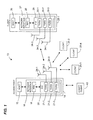
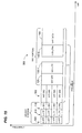
- Fig. 1 is a block diagram of an example wireless local area network (WLAN) 10, according to an embodiment.
- the WLAN 10 supports downlink (DL) multiuser (MU) multiple-input and multiple-output (MIMO) communication between an access point (AP) and a plurality of client stations. Additionally, the WLAN 10 supports DL single-user (SU) communication between the AP and each of a plurality of client stations.
- the AP 14 includes a host processor 15 coupled to a network interface 16.
- the network interface 16 includes a medium access control (MAC) unit 18 and a physical layer (PHY) unit 20.
- the PHY unit 20 includes a plurality of transceivers 21, and the transceivers 21 are coupled to a plurality of antennas 24.
- the AP 14 can include different numbers (e.g., 1, 2, 4, 5, etc.) of transceivers 21 and antennas 24 in other embodiments.
- the MAC unit 18 and the PHY unit 20 are configured to operate according to a first communication protocol (e.g., the IEEE 802.11ac Standard, now in the process of being standardized).
- the MAC unit 18 and the PHY unit 20 are also configured to operate according to a second communication protocol (e.g., the IEEE 802.11n Standard, the IEEE 802.1 la Standard, the IEEE 802.11g Standard, etc.).
- the first communication protocol is referred to herein as a very high throughput (VHT) protocol
- the second communication protocol is referred to herein as a legacy protocol.
- VHT very high throughput
- the WLAN 10 includes a plurality of client stations 25. Although four client stations 25 are illustrated in Fig. 1 , the WLAN 10 includes different numbers (e.g., 1, 2, 3, 5, 6, etc.) of client stations 25 in various scenarios and embodiments. At least one of the client stations 25 (e.g., client station 25-1) is configured to operate at least according to the VHT protocol.
- the WLAN 10 also includes a client station 40 that is not configured to operate according to the VHT protocol but is configured to operate according to the legacy protocol, in some embodiments. Such a client station 40 is referred to herein as a "legacy client station".
- the WLAN 10 includes more than one legacy client station. In other embodiments, the WLAN 10 includes no legacy client stations.
- the client station 25-1 includes a host processor 26 coupled to a network interface 27.
- the network interface 27 includes a MAC unit 28 and a PHY unit 29.
- the PHY unit 29 includes a plurality of transceivers 30, and the transceivers 30 are coupled to a plurality of antennas 34.
- three transceivers 30 and three antennas 34 are illustrated in Fig. 1 , the client station 25-1 includes different numbers (e.g., 1, 2, 4, 5, etc.) of transceivers 30 and antennas 34 in other embodiments.
- one or more of the client stations 25-2, 25-3, and 25-4 have a structure the same as or similar to the client station 25-1.
- the client stations 25 structured the same as or similar to the client station 25-1 have the same or a different number of transceivers and antennas.
- the client station 25-2 has only two transceivers and two antennas, according to an embodiment.
- the PHY unit 20 of the AP 14 is configured to generate data units conforming to the VHT protocol and having formats described hereinafter.
- the transceiver(s) 21 is/are configured to transmit the generated data units via the antenna(s) 24.
- the transceiver(s) 21 is/are configured to receive data units conforming to the VHT protocol via the antenna(s) 24.
- the PHY unit 20 of the AP 14 is configured to process received data units conforming to the VHT protocol and having formats described hereinafter.
- the PHY unit 29 of the client station 25-1 is configured to generate data units conforming to the VHT protocol and having formats described hereinafter.
- the transceiver(s) 30 is/are configured to transmit the generated data units via the antenna(s) 34.
- the transceiver(s) 30 is/are configured to receive data units conforming to the VHT protocol via the antenna(s) 34.
- the PHY unit 29 of the client station 25-1 is configured to process received data units conforming to the VHT protocol and having formats described hereinafter, according to various embodiments.
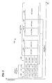
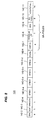
- Fig. 2 is a diagram of a data unit 100 that the AP 14 is configured to transmit data units to the client station 25-1 using orthogonal frequency division multiplexing (OFDM) modulation, according to an embodiment.
- the data unit 100 conforms to the VHT protocol and occupies an 80 MHz band. In other embodiments, data units similar to the data unit 100 occupy different bandwidths such as 20 MHz, 40 MHz, 120 MHz, 160 MHz, or any suitable bandwidth.
- the data unit 100 is suitable for "mixed mode" situations, such as when the WLAN 10 includes a client station (e.g., the legacy client station 40) that conforms to the legacy protocol, but not the VHT protocol.
- the data unit 100 can be utilized in other situations as well.
- the data unit 100 includes a preamble having four legacy short training fields (L-STFs) 105; four legacy long training fields (L-LTFs) 110; four legacy signal fields (L-SIGs) 115; four first very high throughput signal fields (VHT-SIG1s) 120; a very high throughput short training field (VHT-STF) 125; N very high throughput long training fields (VHT-LTFs) 130, where N is an integer; and a second very high throughput signal field (VHT-SIG2) 135.
- the data unit 100 also includes a very high throughput data portion (VHT-DATA) 140.
- the L-STFs 105, the L-LTFs 110, and the L-SIGs 115 form a legacy portion.
- the VHT-STF 125, the VHT-LTFs 130, the VHT-SIG2 135, and the VHT-DATA 140 form a very high throughput (VHT) portion.
- Each of the L-STFs 105, each of the L-LTFs 110, each of the L-SIGs 115, and each of the VHT-SIG1s 120 occupy a 20 MHz band, in one embodiment.
- several example data units, including the data unit 100, having an 80 MHz contiguous bandwidth are described for the purposes of illustrating embodiments of frame formats, but these frame format embodiments and other embodiments are applicable to other suitable bandwidths (including noncontiguous bandwidths).
- the preamble of the data unit 100 includes four of each of the L-STFs 105, the L-LTFs 110, the L-SIGs 115, and the VHT-SIG1s 120
- an OFDM data unit occupies a cumulative bandwidth other than 80 MHz, such as 20 MHz, 40 MHz, 120 MHz, 160 MHz, etc.
- a different suitable number of the L-STFs 105, the L-LTFs 110, the L-SIGs 115, and the VHT-SIG1s 120 are utilized accordingly.
- the data unit includes one of each of the L-STFs 105, the L-LTFs 110, the L-SIGs 115, and the VHT-SIG1s 120; a 40 MHz bandwidth OFDM data unit includes two of each of the fields 105, 110, 115, and 120; a 120 MHz bandwidth OFDM data unit includes six of each of the fields 105, 110, 115, and 120; a 160 MHz bandwidth OFDM data unit includes eight of each of the fields 105, 110, 115, and 120, and so on, according to some embodiments.
- each of the VHT-STF 125, the VHT-LTFs 130, the VHT-SIG2 135, and the VHT-DATA 140 occupy the entire 80 MHz cumulative bandwidth of the data unit 100.
- each of the VHT-STF 125, the VHT-LTFs 130, the VHT-SIG2 135, and the VHT-DATA 140 occupy the corresponding entire cumulative bandwidth of the data unit, in some embodiments.
- the 80 MHz band of the data unit 100 is not contiguous, but includes two or more smaller bands, such as two 40 MHz bands, separated in frequency.
- the band is not contiguous in frequency.
- the L-STFs 105, the L-LTFs 110, the L-SIGs 115, and the VHT-SIG1s 120 occupy two or more bands that are separated from each other in frequency, and adjacent bands are separated in frequency by at least one MHz, at least five MHz, at least 10 MHz, at least 20 MHz, for example, in some embodiments.
- each of the L-STFs 105 and each of the L-LTFs 110 have a format as specified in a legacy protocol such as the IEEE 802.11 a Standard and/or the IEEE 802.11n Standard.
- each of the L-SIGs 115 has a format at least substantially as specified in legacy protocol (e.g., the IEEE 802.11a Standard and/or the IEEE 802.11n Standard).
- the length and rate subfields in the L-SIGs 115 is set to indicate the duration T corresponding to the remainder of the data unit 100 after the legacy portion. This permits client stations that are not configured according to the VHT protocol to determine an end of the data unit 100 for carrier sense multiple access/collision avoidance (CSMA/CA) purposes, for example.
- CSMA/CA carrier sense multiple access/collision avoidance
- a legacy client station configured according to the IEEE 802.11a Standard detects a data error from the VHT-SIG1s 120, according to the receiver state machine specified in the IEEE 802.11a Standard. In this situation, the legacy client station waits until the end of the duration T before performing clear channel assessment (CCA).
- CCA clear channel assessment
- a legacy client station configured according to the IEEE 802.11n Standard will detect an error in response to receiving the VHT-SIG1s 120 and/or the VHT-SIG2 135, such as a cyclic redundancy check (CRC) error. In this situation, the legacy client station waits until the energy of the data unit 100 drops out before switching to CCA idle mode.
- CCA cyclic redundancy check
- the frequency domain symbols of the legacy portion are repeated over four 20 MHz subbands of the 80 MHz band.
- Legacy client stations that are configured according to the IEEE 802.11 a Standard and/or the IEEE 802.11n Standard with 20 MHz bandwidth will recognize a legacy IEEE 802.11 a Standard preamble in any of the 20 MHz subbands.
- the modulations of the different 20 MHz subband signals are rotated by different angles. In one example, a first subband is rotated 0 degrees, a second subband is rotated 90 degrees, a third subband is rotated 180 degrees, and a fourth subband is rotated 270 degrees, in an embodiment. In other examples, different suitable rotations are utilized. As just one example, a first subband is rotated 45 degrees, a second subband is rotated 90 degrees, a third subband is rotated -45 degrees, and a fourth subband is rotated -90 degrees, in an embodiment.
- the modulations of the VHT-SIG1s 120 in the different 20 MHz subbands is rotated by different angles.
- a first subband is rotated 0 degrees
- a second subband is rotated 90 degrees
- a third subband is rotated 180 degrees
- a fourth subband is rotated 270 degrees, in an embodiment.
- different suitable rotations are utilized.
- a first subband is rotated 45 degrees
- a second subband is rotated 90 degrees
- a third subband is rotated -45 degrees
- a fourth subband is rotated -90 degrees, in an embodiment.
- the same rotations utilized in the legacy portion are utilized for the VHT-SIG1s 120.
- the VHT-SIG1s 120 are collectively referred to as a single first very high throughput signal field (VHT-SIG1) 120.
- the VHT-SIG2 135 are included after one or more of the VHT-LTFs 130 and are spatially mapped the same way as one of the one or more VHT-LTFs 130.
- the VHT-SIG2 135 are spatially mapped by a vector QP 1 , where Q is an antenna map or spatial mapping matrix that maps spatial streams, or space-time streams if space-time encoding is utilized, to transmit antennas, and P 1 is a first column in a spatial stream mapping matrix P , which is a Hadamard matrix in which each element of P is +1 or -1, in an embodiment.
- each element of P is a complex number (e.g., a Discrete Fourier Transform matrix is used as P ).
- some elements of P are integers other than +1 or -1.
- P 1 corresponds to a first spatial stream.
- each VHT-LTF is generated, a separate column of the matrix P is used to map the values to spatial streams.
- the first column of the matrix P i.e., P 1
- the second column of the matrix P i.e., P 2
- a client station 25 may use the channel estimation from the VHT-LTF1 to decode the VHT-SIG2 135, in an embodiment.
- the VHT-SIG2 is spatially mapped by a vector QP N so that a client station 25 may use the channel estimation from the VHT-LTFN 130-N to decode the VHT-SIG2 135, in another embodiment.
- Various other suitable embodiments of the data unit 100, including various suitable positions of the VHT-SIG2 135, are described in U.S. Patent Application No. 12/758,603 , entitled "Physical Layer Frame Format for WLAN," filed on April 12, 201 0.
- the PHY unit 20, the transceivers 21, and the antennas 24 may implement space-division multiple access (SDMA) downlink transmissions which differentiate the VHT-SIG2 135 for different users by beam-steering, while the L-STFs 105, the L-LTFs 110, the L-SIGs 115, and the VHT-SIG1s 120 remain unsteered (or "omnidirectional" or "pseudo-omnidirectional"; the terms "unsteered” and “omnidirectional” as used herein are intended to also encompass the term “pseudo-omnidirectional") and contain PHY information that is common to each of the client stations 25.
- SDMA space-division multiple access
- the VHT-SIG2 135 includes different data for different clients 25 that are simultaneously transmitted, via the antennas 24, over different spatial channels to carry different (or "user-specific") content to each of the client stations 25.
- the VHT-SIG2 135 illustrated in Fig. 2 represents different information being transmitted to different clients via different spatial streams, in some embodiments.
- the VHT-SIG2 135, and other steered portions of the various data units disclosed herein may at times be illustrated and/or described herein in this manner.
- the VHT-SIG2 135 and other such steered portions may include different information being transmitted to different clients via different spatial streams, in some embodiments as discussed above, for example.
- the VHT-SIG1 120 comprises two OFDM symbols, according to an embodiment.
- the VHT-SIG2 135 comprises one OFDM symbol, according to an embodiment.
- the preamble of the data unit 100 allows each client station 25 to estimate at least a portion of the signal channel from the AP 14 to the client station 25, and based on this estimation, equalize the channel to decode data (e.g., within the VHT-DATA 140) transmitted from the AP 14 to the client station 25 (e.g., the client station 25-1).
- the client station 25-1 determines a number of channel dimensions from the AP 14 to the client station 25-1 and estimates each of the channel dimensions using one or more of the VHT-LTFs 130, in an embodiment.
- the data unit 100 indicates a number of spatial streams, or space-time streams if space-time encoding is utilized, transmitted from the AP 14 to each of the client stations 25, and the client station 25-1 may further determine which particular spatial streams or space-time streams transmitted from the AP 14 include information for the client station 25-1.
- the AP 14 transmits a corresponding number of the VHT-LTFs 130 to the client station 25-1, in an embodiment.
- one or more of the VHT-LTFs 130 that are allocated to a particular client station 25 for channel estimation are not allocated to one or more of the other client stations 25 for channel estimation.
- the PHY unit 20 generates at least enough VHT-LTFs 130 to jointly train all of the client stations 25 to estimate the signal channels corresponding thereto.
- the data unit 100 indicates the number of spatial streams, or space-time streams if space-time encoding is utilized, transmitted from the AP 14 to each of the client stations 25.
- each client station 25 receives all of the VHT-LTFs 130 and uses the indication of the number of spatial or space-time streams to determine which ones of the VHT-LTFs 130 to use for its own channel estimation, in advance of receiving the VHT-LTFs 130.
- the indications of the number of spatial/space-time streams corresponding to a particular client station 25 are included in the VHT-SIG2 135.
- the data unit 100 also or alternatively includes a suitable indication of the corresponding number of spatial/space-time streams in the VHT-SIG1 120, in an embodiment. Several examples of such an indication are described in detail below.
- each client station 25 avoids buffering other ones of the VHT-LTFs 130 in memory that are not needed for channel estimation, in an embodiment.
- Such an advance determination also allows the client station 25 to begin channel estimation substantially contemporaneously with receipt of the VHT-LTFs 130, in an embodiment. For instance, if the beginning of channel estimation is delayed beyond receipt of the VHT-LTFs 130 corresponding to the spatial/space-time streams for the client station 25, the client station 25 may need to be able to rapidly perform channel estimation and determine an equalizer for the channel in time to accurately decode the data in the VHT-DATA 140. Such rapid channel estimation may create an undesirable processing load on the PHY unit 29, in some embodiments.
- each client station 25 also attempts to mitigate, or "whiten", interference resulting from the spatial/space-time streams sent to other ones of the client stations 25. Therefore, the data unit 100 enables each client station 25 to determine not only the number of spatial/space-time streams from the AP 14 to the client station 25, but also the numbers of spatial/space-time streams from the AP 14 to each other one of the client stations 25, in an embodiment.
- the data unit 100 also enables each client station 25 to determine which ones of the VHT-LTFs 130 each other client station 25 needs to use for channel estimation.
- Each client station 25 uses the channel training information for the other client stations 25 to mitigate received interference from the spatial/space-time streams sent to each of the other client stations 25.
- the data unit 100 advantageously allows each client station 25 to make an advance determination of which ones of the VHT-LTFs 130 to use for channel estimation, even though others of the VHT-LTFs 130 are used for interference mitigation or whitening.
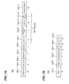
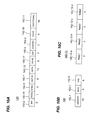
- Figs. 3A and 3B are diagrams of example bit allocations for the VHT-SIG1 120 and VHT-SIG2 135, respectively, according to an embodiment.
- the example bit allocations of Figs. 3A and 3B are used when the AP 14 is supporting downlink multiuser MIMO (DL-MUMIMO) communication, in an embodiment.
- DL-MUMIMO downlink multiuser MIMO
- the VHT-SIG1 120 includes a plurality of subfields 142.
- the plurality of subfields 142 includes a duration subfield 142-1, a bandwidth subfield 142-2, a short guard interval (SGI) subfield 142-3, a smoothing subfield 142-4, a space-time block coding (STBC) subfield 142-5, a multi-user (MU)/single-user (SU) subfield 142-6, a group ID subfield 142-7, a resolvable LTF subfield 142-8, a number of spatial streams (Nss) subfield 142-9, and an MU reserved subfield 142-10 which may be for implementing MU features developed in the future, etc.
- the VHT-SIG1 120 also includes one or more additional subfields which are collectively referred to as additional subfields 142-11.
- the additional subfields 142-11 include, for example, one or more of a cyclic redundancy check (CRC) subfield, a subfield including tail bits, a reserved subfield for implementing features developed in the future, etc., in
- the MU/SU subfield 142-6 includes a single bit which is set to a logic "1" to indicate that the AP 14 is operating in MU mode.
- the single bit in the MU/SU subfield 142-6 is set to a logic "0" to indicate that the AP 14 is operating in MU mode.
- the group ID subfield 142-7 indicates an MU group to which the data unit 100 is directed, in an embodiment. In some other embodiments, the MU/SU subfield 142-6 is removed, and one of the possible bit sequences of the group ID subfield 142-7 is reserved for the purpose of indicating that the data unit 100 is an SU data unit.
- every bit in the group ID subfield 142-7 is set to a logic "1" to indicate SU mode, in an embodiment.
- every bit in the group ID subfield 142-7 is set to a logic "0" to indicate SU mode, in an embodiment.
- one possible bit sequence of the group ID subfield 142-7 is used to indicate that the data unit 100 is a broadcast frame, in addition to or instead of using one possible bit sequence of the group ID subfield 142-7 to indicate that the data unit 100 is an SU data unit.
- the bit sequence of the group ID subfield 142-7 used to indicate that the data unit 100 is a broadcast frame is the same bit sequence which is used when the data unit 100 is an SU data unit.
- the bit sequence of the group ID subfield 142-7 which is used when the data unit 100 is an SU data unit is also used when the data unit 100 is an MU data unit but one or more of the client stations 25 have not been assigned to an MU group, according to an embodiment.
- the STBC subfield 142-5 and the Nss subfield 142-9 provide indications of numbers of space-time streams for each of the client stations 25.
- the number of space-time streams corresponding to a client station 25 is a number of spatial streams transmitted to the client station 25 via the antennas 24 when STBC is not used. Accordingly, for purposes of the present disclosure, a spatial stream that is not encoded using STBC may at times be referred to herein as a space-time stream for ease of explanation.
- the number of space-time streams corresponding to the client station 25 are determined by the number of spatial streams corresponding to the client station 25 and by a particular space-time block code being used, such as an Alamouti code. For example, encoding a single spatial stream with an Alamouti code results in two space-time streams.
- the STBC setting is the same for each of the client stations 25, and as such only a single bit is required in the STBC subfield 142-5 to indicate whether STBC is being used.
- the STBC subfield 142-5 includes one bit, which is, for example, set to "1" if STBC is being used and "0" if STBC is not being used, or vice versa.
- the number of spatial streams corresponding to each of the client stations 25 is different. Each of the client stations 25 determines its corresponding number of spatial streams using a unique index value assigned to that client station 25 using a management frame or control frame, such as a sounding frame.
- the AP 14 assigns a unique index value to each of the client stations 25 prior to transmission of the data unit 100 by first transmitting a sounding frame to each of the client stations 25.
- the sounding frame includes one or more group definition fields.
- Fig. 4 is a diagram of an example group definition field 160.
- the group definition field 160 includes a group identifier (group ID) subfield 162 and one or more association identifier (AID) sub fields 164.
- the AID subfields 164 include as many subfields as there are MU-MIMO users assigned to a group identified by the group ID subfield 162 (i.e., an "MU group"). For example, as shown in Fig.
- the AID subfields 164 include a first AID (AID1) subfield 164-1, a second AID (AID2) subfield 164-2, a third AID (AID3) subfield 164-3, and a fourth AID (AID4) subfield 164-4.
- the group definition field 160 is generated by the PHY unit 20.
- at least one of the AID subfields 164, and/or information included therein, are generated at least in part by the MAC unit 18.
- Each of the AID subfields 164 includes an AID of one of the client stations 25 that the AP 14 has assigned to the MU group identified by the group ID subfield 162.
- Each one of the client stations 25 is configured to receive the entire group definition field 160 and, after detecting its own AID within one of the AID subfields 164, determine that the particular client station 25 is a member of the MU group identified by the group ID subfield 162.
- Each client station 25 further determines, based on the placement of its own AID relative to the AIDs of the other client stations 25 in the AID subfields 164, the order in which the indication of its own number of spatial streams is transmitted in the Nss subfield 142-9, relative to the indications for the other client stations 25.
- the group definition field 160 does not include the AID of a particular client station 25
- that client station 25 determines that it is not a member of the MU group identified by the group ID subfield 162 and, for example, monitors subsequent group definition fields within the same or a different sounding frame until the client station 25 determines an MU group to which it belongs, in an embodiment.
- the client station 25-2 detects the first AID subfield 164-1 and determines that the AID in the first AID subfield 164-1 does not match the AID of the client station 25-2.
- the client station 25-2 detects the second AID subfield 164-2 and determines that the AID in the second AID subfield 164-2 matches the AID of the client station 25-2.
- the client station 25-2 therefore determines that it is a member of the MU group identified by the group ID subfield 162, and further determines that its unique index value is the number two, i.e., that the indication of its own number of spatial streams will be the second indication within the Nss subfield 142-9 in order of receipt.
- the second client station 25-2 Based on detection of the AIDs in the other AID subfields 164-1, 164-3, and 164-4, the second client station 25-2 also determines the unique index values assigned to the other client stations 25-1, 25-3, and 25-4.
- the AID of a particular client station such as the client station 25-2, is included in any other suitable one of the AID subfields 164 (e.g., the subfield 164-1, the subfield 164-3, etc.), in some embodiments.
- the AP 14 is configured to transmit a sounding frame including the group definition field 160 to each of the client stations 25.
- the sounding frame also is used to request an acknowledgement from each one of the client stations 25 of the user index value associated therewith, and to request channel measurement feedback, in an embodiment.
- the AP 14 determines the spatial mapping Q matrix for the client stations 25 by processing responsive feedback frames.
- the PHY unit 20 is configured to use the Q matrix to generate the VHT-SIG2 135, which the transceivers 21 and the antennas 24 transmits to the different client stations 25 simultaneously over a plurality of different spatial channels.
- VHT-SIG2 135 Various example implementations of beam-steering of signal fields such as the VHT-SIG2 135 are described in U.S. Patent Application No.
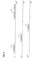
- Fig. 5 is an example timing diagram that shows a sounding frame 170 being transmitted from the AP 14 to each of the client stations 25, according to an embodiment.
- the AP 14 broadcasts the sounding frame 170 to the client stations 25.
- the AP 14 transmits multiple sounding frames to the client stations 25, where a different one of the sounding frames is transmitted to each one of the client stations 25.
- the disclosure herein will refer to the sounding frame 170 being transmitted to each of the client stations 25 (e.g., the client stations 25-1 and 25-2).
- the sounding frame 170 includes a payload portion, which includes the group definition field 160, according to an embodiment.
- the sounding frame 170 omits a payload portion, and the group definition field 160 is included in a PHY preamble portion.
- the PHY unit 29 of the client station 25-1 in response to the client station 25-1 receiving the sounding frame 170 and receiving and recording its associated user index value contained therein, the PHY unit 29 of the client station 25-1 generates a feedback frame 172 for transmission to the AP 14 during a first time slot.
- the PHY unit 29 of the client station 25-2 in response to the client station 25-2 receiving the sounding frame 170 and receiving and recording its associated user index value contained therein, the PHY unit 29 of the client station 25-2 generates a feedback frame 174 for transmission to the AP 14 during a second time slot, and so on for any other ones of the client stations 25.
- Each of the feedback frames 172 and 174 includes a suitable acknowledgement that the corresponding one of the client stations 25 has received and recorded its associated user index value.
- the AP 14 verifies that each of the client station 25-1 and the client station 25-2 correctly recorded its assigned user index value.
- the AP 14 also uses the feedback frames 172 and 174 to determine the spatial mapping Q matrix, as discussed above.
- the group definition field 160 is transmitted within a non-sounding management frame, according to an embodiment.
- the AP 14 uses a non-sounding management frame to implement a "stand-alone" MAC or AID exchange, e.g., an association of MAC addresses or AIDs of the client stations 25 with group IDs and user index values without a request for channel measurement feedback, in an embodiment.
- the MAC unit 18 generates at least part of the non-sounding management frame and/or the information therein.
- the PHY unit 20 generates the non-sounding management frame.
- a payload portion of the management frame associates a MAC address or AID of the client station 25-1 with a group ID and a first index value, such as the number one, according to an embodiment.
- the data portion further associates a MAC address or AID of the client station 25-2 with the same group ID and a second index value, a MAC address or AID of the client station 25-3 with the same group ID and a third index value, and a MAC address or AID of the client station 25-4 with the same group ID and a fourth index value, according to an embodiment.
- the non-sounding management frame is a unicast frame that assigns multiple group IDs and associated unique index values for each group ID to a single client station 25.
- the non-sounding management frame is a multicast frame that is transmitted to an entire MU group. The multicast frame assigns multiple group IDs, and associated unique index values for each group ID, to one or more client stations 25 in the MU group to which the multicast frame is transmitted.
- the unique index values assigned to the client stations 25 are refreshed each time the AP 14 transmits a sounding frame or other management frame. According to another embodiment, the unique index values assigned to the client stations 25 are refreshed less frequently. For example, the unique index values are refreshed every second time the AP 14 transmits a sounding frame or other management frame, every third time, etc., according to other embodiments. The frequency with which the unique index values are refreshed depends on a degree and/or rate of change of the characteristics of the signal channels between the AP 14 and the client stations 25, according to an embodiment.
- the client station 25 determines, upon receipt of the group ID subfield 142-7, whether the group ID subfield 142-7 matches the group ID subfield 162 or an ID of any other MU group to which the client station 25 belongs. For example, the client station 25 is assigned to multiple MU groups using multiple group definition fields 160, or other suitable management frames or control frames, in some embodiments. If the client station 25 determines that the group ID subfield 142-7 matches the group ID subfield 162 or the group ID of any other MU group to which the client station 25 belongs, the client station 25 processes the entire VHT-SIG1 120.
- the client station 25 thereby determines its corresponding number of space-time streams. According to an embodiment, if the group ID subfield 142-7 does not match the group ID subfield 162 or the group ID of any other MU group to which the client station 25 belongs, the client station 25 determines that it is not a member of the MU group to which the data unit 100 is directed and disregards the remainder of the data unit 100. By disregarding the remainder of the data unit 100, the client station 25 conserves power by, for example, not attempting to receive and/or decode the remainder of the data unit 100.
- one possible bit sequence of the group ID subfield 142-7 is reserved for the purpose of indicating that the data unit 100 is an SU data unit. Therefore, if the group ID subfield 142-7 does not match the group ID subfield 162 pertaining to a previous MU transmission, but the group ID 142-7 does match the reserved bit sequence, the client station 25 determines that the data unit 100 is an SU data unit, in some embodiments,
- the Nss subfield 142-9 itself includes a plurality of subfields. Each one of the plurality of Nss sub-subfields includes information for one of each of the client stations 25.
- Fig. 6 is a diagram of Nss subfield 142-9 showing that Nss subfield 142-9 is formed from four Nss sub-subfields 142-9-a, 142-9-b, 142-9-c, and 142-9-d, according to an embodiment.
- the Nss sub-subfields 142-9-a, 142-9-b, 142-9-c, and 142-9-d are labeled Nss1, Nss2, Nss3, and Nss4, respectively, and each includes an indication of the number of spatial streams allocated to the corresponding client, according to an embodiment.
- the Nss subfield 142-9 includes a total of eight bits, such that two bits are allocated to each of the Nss sub-subfields 142-9-a, 142-9-b, 142-9-c, and 142-9-d as shown in Fig. 6 , in an embodiment.
- Each client station 25 each receives the entire Nss subfield 142-9, but determines which of the Nss sub-subfields 142-9-a, 142-9-b, 142-9-c, and 142-9-d corresponds to the client station 25 by using the unique index value assigned to the client station 25 (during the group definition process or other process of assigning a group ID and unique index value, as described above) in conjunction with prior knowledge of the number of bits in each of the Nss sub-subfields 142-9-a, 142-9-b, 142-9-c, and 142-9-d.
- the client station 25 performs interference mitigation
- the client station 25 also determines the number of space-time streams for the other client stations 25 using the STBC subfield 142-5 in conjunction with knowledge of the unique index values assigned to the other client stations 25.
- the Nss subfield 142-9 indicates whether 0, 1, 2, or 3 spatial streams are allocated to each of the client stations 25-1, 25-2, 25-3, and 25-4 of the WLAN 10, according to an embodiment.
- the Nss subfield 142-9 indicates another suitable range of numbers of spatial streams, in other embodiments.
- the VHT-SIG2 135 indicates a modulation and coding scheme (MCS) for each of the client stations 25 using a sequence of bits for each client station 25, where one such sequence indicates that no data is being transmitted to the corresponding client station 25, in an embodiment.
- MCS modulation and coding scheme
- the two bits in each Nss sub-subfield are used to indicate whether 1, 2, 3, or 4 spatial streams are allocated to each of the client stations 25-1, 25-2, 25-3, and 25-4, according to an embodiment.
- different numbers of bits are allocated to the Nss subfield 142-9.
- the Nss subfield 142-9 indicates the numbers of spatial streams for more or less than four client stations 25, according to some embodiments.
- the example bit allocation for VHT-SIG2 135 of Fig. 3B is implemented in conjunction with the example bit allocation shown in Fig. 3A , and/or with any other suitable bit allocation for the VHT-SIG1 120.
- the VHT-SIG2 135 includes a plurality of subfields 152.
- the plurality of subfields 152 includes an MCS subfield 152-1, a coding type subfield 152-2, a reserved subfield 152-3 (e.g., for implementing features developed in the future), a CRC subfield 152-4, and a subfield 152-5 including tail bits.
- the MCS subfield 152-1 specifies a modulation and coding scheme (MCS) that the AP 14 uses in generating and transmitting the space-time streams corresponding to each client station 25.
- MCS modulation and coding scheme
- the data unit 100 allows the indications of the MCS for each client station 25 to be included within the VHT-SIG2 135, while advantageously providing complete indications of the numbers of space-time streams for each client station 25 in the VHT-SIG1 120 using the STBC subfield 142-5 and the Nss subfield 142-9.
- Each of the client stations 25 processes the STBC subfield 142-5 and the Nss subfield 142-9 before receiving the VHT-LTFs 130. Therefore, each client station 25 is enabled to process, without buffering, only those ones of the received VHT-LTFs 130 that the client station 25 needs to determine the equalizer for its own space-time streams, according to an embodiment.
- the client station 25 processes VHT-LTFs 130 that correspond to other stations for interference mitigation purposes, for example.
- the client stations 25 each determines which ones of the space-time streams, and which ones of the VHT-LTFs 130, to process based on the unique index values assigned by the AP 14. According to an embodiment, the client stations 25 use the unique index values in conjunction with knowledge of a spatial mapping Q matrix in order to determine which space-time streams and which ones of the VHT-LTFs 130 to process.
- the Nss subfield 142-9 specifies an index value which in turn specifies an entry in a lookup table (LUT).
- the LUT has a plurality of entries, and each entry indicates numbers of spatial streams for one or more client stations 25.
- the LUT therefore specifies suitable combinations of numbers of spatial streams that are allocated to the various client stations 25.
- the Nss subfield 142-9 includes eight bits and therefore specifies any of 256 different index values corresponding to 256 entries in the LUT, according to an embodiment.
- other suitable indications of a number of space-time streams are utilized in other embodiments.
- Figs. 7A and 7B are diagrams of example bit allocations for the VHT-SIG1 120 and the VHT-SIG2 135, according to an embodiment.
- the bit allocations of Figs. 7A and 7B are similar to those of Figs. 3A and 3B , except that the STBC subfield 142-5 is removed from the VHT-SIG1 120 and an STBC subfield 152-6 is included in the VHT-SIG2 135.
- the Nss subfield 142-9 is replaced with an Nsts subfield 142-12, which indicates a number of space-time streams for each client station 25.
- the Nsts subfield 142-12 indicates an index to a LUT having different combinations of space-time streams.
- the Nsts subfield 142-12 includes nine bits, according to the embodiment illustrated in Fig. 7A .
- the STBC subfield 142-5 is not needed to determine the number of space-time streams for a particular client station 25. Because the PHY unit 20 is configured to generate different VHT-SIG2 135 data for simultaneous transmission to different client stations 25, including the STBC subfield 152-6, the VHT-SIG2 135 allows user-specific control of STBC settings. Therefore, in an embodiment, STBC may be used for the spatial streams corresponding to some of the client stations 25 but not for the spatial streams corresponding to other ones of the client stations 25.
- each client station 25 determines an equalizer for its space-time streams based on its number of space-time streams, and not based on the number of spatial streams corresponding to the client station 25. If the Nsts subfield 142-12 indicates, for example, that two space-time streams correspond to the client station 25, the same equalizer is determined regardless of whether STBC is not used and the number of spatial streams is two, or STBC is used and the number of spatial streams is one, according to an embodiment.
- the client station 25 groups OFDM symbols together in pairs (e.g., one OFDM symbol from each space-time stream), for example, and performs STBC decoding after at least a portion of the equalization has been performed, according to an embodiment.
- use of the Nsts subfield 142-12 allows more bits in the VHT-SIG1 120 to be utilized for purposes other than indicating numbers of space-time streams.
- the Nsts subfield 142-12 is implemented with eight or fewer bits, according to an embodiment. In such an embodiment, removing the STBC subfield 142-5 from the VHT-SIG1 120 results in fewer total bits in the VHT-SIG1 120 being used to indicate the numbers of space-time streams for the client stations 25 as compared to, for example, the bit allocation of Fig. 3A .
- the Nsts subfield 142-12 or a similar subfield is included in the VHT-SIG1 120 along with the STBC subfield 142-5 or a similar subfield.
- Fig. 8 is a diagram of still another example bit allocation for the VHT-SIG1 120 which is used when, for example, the L-SIGs 115 indicate the duration T of the data unit 100 after the legacy portion, in another embodiment.
- the rate subfield in the L-SIGs 115 is set to 6 Mbps
- the length subfield is set such that the rate and length subfields together indicate the duration T.
- the VHT-SIG1 120 therefore is implemented without the duration subfield 142-1, which thus frees twelve bits of the VHT-SIG1 120 for other uses, according to an embodiment. For example, as shown in Fig.
- the STBC subfield 142-5 is implemented as a plurality of STBC sub-subfields 142-5-a, 142-5-b, 142-5-c, and 142-5-d, which are denoted STBC1, STBC2, STBC3, and STBC4, respectively.
- the STBC sub-subfields 142-5-a, 142-5-b, 142-5-c, and 142-5-d each corresponds to one of the client stations 25-1, 25-2, 25-3, and 25-4, according to an embodiment.
- Each of the STBC sub-subfields 142-5-a, 142-5-b, 142-5-c, and 142-5-d includes a single bit that indicates whether space-time streams for the corresponding client station 25 are encoded, using an Alamouti code for example, or whether STBC is not being used with the spatial streams for the corresponding client station 25, according to an embodiment.
- the example bit allocation of Fig. 8 therefore is used to indicate user-specific STBC settings in the VHT-SIG1 120 so that the STBC setting need not be the same for all of the client stations 25.
- the other excess bits in the example of Fig. 8 are included in the MU reserved subfield 142-10.
- One of ordinary skill in the art will also recognize additional and/or alternative suitable uses for the excess bits in light of the teachings and disclosure herein.
- the AP 14 also operates in single-user (SU) mode, where the AP 14 supports downlink single-user wireless communication.
- the data unit 100 also is used to transmit information to a client station 25 in SU mode, in some embodiments.
- SU mode the VHT-SIG1 120 is implemented without some of the subfields 142 described above with respect to various embodiments in MU mode.
- the VHT-SIG2 135 is implemented without some of the subfields 152 in SU mode, or is removed altogether.
- Figs. 9A and 9B are diagrams of example bit allocations for the VHT-SIG1 120 and VHT-SIG2 135, respectively, for SU mode.
- the VHT-SIG1 120 includes the duration subfield 142-1, the bandwidth subfield 142-2, the SGI subfield 142-3, the smoothing subfield 142-4, the MU/SU subfield 142-6, the MCS subfield 152-1, an STBC subfield 142-13, the coding type subfield 152-2, a non-sounding subfield 142-14, an AID subfield 142-15, and the additional subfields 142-11 (such as a CRC subfield and a subfield including tail bits), in an embodiment.
- the AP 14 indicates that the data unit 100 is being transmitted in SU mode by way of setting the bit in the MU/SU subfield 142-6 to a logic "0", according to an embodiment.
- the MU/SU subfield 142-6 is removed, and the VHT-SIG1 120 includes the group ID subfield 142-7 in both MU mode and SU mode. Therefore, the group ID subfield 142-7 is set to a reserved bit sequence to indicate that the data unit 100 is an SU data unit, in an embodiment.
- the VHT-SIG1 120 is implemented without the group ID subfield 142-7, the resolvable LTF subfield 142-8, and the Nss subfield 142-9, according to an embodiment. That is, the data unit 100 does not specify an MU group when supporting SU communication, and enough bits are then freed in the VHT-SIG1 120 to indicate the number of space-time streams for the single client station 25 using the MCS subfield 152-1, thus rendering the Nss subfield 142-9 unnecessary.
- the MCS subfield 152-1 is implemented so that it indicates a number of spatial streams for a client station 25 involved in SU communication, according to an embodiment.
- This indication is used together with an STBC setting indicated by the STBC subfield 142-13 to provide a complete indication of the number of space-time streams transmitted from the AP 14 to the client 25.
- one or more embodiments enable the client station 25 to begin estimating the signal channel between the AP 14 and the client station 25 substantially contemporaneously with receipt of the VHT-LTFs 130.
- the client station 25 determines that the AP 14 is communicating in SU mode based on the group ID subfield 142-7 or any other suitable aspect of the structure of the data unit 100, such as the MU/SU subfield 142-6, in some embodiments.
- the client station 25 then performs signal channel estimation using all or a portion of the VHT-LTFs 130. For example, some of the VHT-LTFs 130 may be repeated, and the client station 25 may therefore perform signal channel estimation using less than all of the VHT-LTFs 130, according to an embodiment.
- the Nss subfield 142-9 is not removed, and the VHT-SIG1 120 therefore includes indications of each of the number of spatial streams, the MCS, and the STBC setting in separate subfields.
- the AID subfield 142-15 or one or more bits from any other suitable subfield or subfields, is/are removed from the example bit allocation of Fig. 9A to allow a sufficient number of bits for the Nss subfield 142-9.
- the Nss subfield 142-9 is replaced with the Nsts subfield 142-12.
- the AP 14 may have more options for implementing STBC in SU mode. For example, in Fig. 9A , the VHT-SIG1 120 has enough otherwise-unused bits such that the STBC subfield 142-13 includes two bits instead of the single bit in the STBC subfield 142-5. With two bits identifying up to four possible STBC settings, the AP 14 is able to choose between no STBC at all, an Alamouti code, and two higher-order codes, according to an embodiment.
- the VHT-SIG1 120 also has enough otherwise-unused bits to include PHY information that is not included in either the VHT-SIG1 120 or the VHT-SIG2 135 in MU mode, in an embodiment.
- the bit allocation of Fig. 9A includes one bit for the not-sounding subfield 142-14 and three bits for the AID subfield 142-15.
- the not-sounding subfield 142-14 indicates whether the data unit 100 is a sounding packet, for example.
- the AID subfield 142-15 includes the last three bits of the MAC ID or AID of a client station to which the data unit 100 is being transmitted, in some embodiments.
- the PHY unit 29 of a client station 25 stops attempting to receive and decode for the duration of the data unit 100 if the PHY unit 29 determines that the AID subfield 142-15 does not match the last three bits of the AID of the client station 25. In this manner, the PHY unit 29 of the client station 25 determines early in the reception of the data unit 100 that the SU transmission is not intended for the client station 25, and conserves power, for example, by not attempting to receive and decode.
- the VHT-SIG2 135 includes the reserved subfield 152-3, the CRC subfield 152-4, and the subfield 152-5 including tail bits. Alternatively, if the reserved subfield 152-3 is not needed to implement any additional features, the VHT-SIG2 135 is simply eliminated from the data unit 100, according to an embodiment.
- Figs. 10A-10C are diagrams of example bit allocations for the VHT-SIG1 120 and the VHT-SIG2 135 for use in MU mode, according to yet another embodiment.
- the VHT-SIG1 120 includes the bandwidth subfield 142-2, a reserved subfield 142-16, the STBC subfield 142-5, the group ID subfield 142-7, the Nsts subfield 142-12, another reserved subfield 142-17, the SGI subfield 142-3, the coding subfield 152-2, still another reserved subfield 142-18, and the additional subfields 142-11.
- the VHT-SIG1 120 does not include the duration subfield 142-1, for example.
- the duration T of the data unit 100 after the legacy portion is indicated by the rate and length subfields in the L-SIGs 115, such as in the manner described with respect to Fig. 8 .
- the bandwidth subfield 142-2 includes two bits to indicate one of four possibilities for the bandwidth of the data unit 100.
- the bandwidth subfield 142-2 indicates that the bandwidth of the data unit 100 is 20 MHz, 40 MHz, 80 MHz, or 160 MHz (either contiguous or two 80 MHz bands), in an embodiment.
- the reserved subfield 142-16 includes a single bit set to a logic "1", according to an embodiment.
- the reserved subfield 142-16 is, for example, reserved for possible expansion of the bandwidth subfield 142-2.
- the STBC subfield 142-5 includes a single bit indicating whether or not the data unit 100 is encoded using STBC, as described above, in an embodiment.
- the group ID subfield 142-7 is implemented using six bits, and is used to indicate that the data unit 100 is, for example, an SU data unit, as described further below.
- the reserved subfields 142-17 and 142-18 include two bits and six bits, respectively, all of which are set to a logic "1", according to an embodiment.
- the SGI subfield 142-3 includes two bits, one of which is used to indicate whether the guard interval of the data unit 100 is long or short, and one of which is used for short GI packet length ambiguity mitigation, according to an embodiment.
- the coding subfield 152-2 includes two bits, at least one of which is used to indicate a coding type used for the data unit 100, such as a binary convolutional code (BCC) or a low-density parity-check (LDPC) code, in an embodiment.
- BCC binary convolutional code
- LDPC low-density parity-check
- the Nsts subfield 142-12 is implemented using twelve bits, and includes Nsts sub-subfields 142-12-a, 142-12-b, 142-12-c, and 142-12-d to provide an indication of up to four numbers of space-time streams for up to four respective client stations 25, as shown in Fig. 10C .
- Each of the Nsts sub-subfields 142-12-a, 142-12-b, 142-12-c, and 142-12-d includes, for example, three bits.
- five possible combinations of the three bits in each of the Nsts sub-subfields 142-12-a, 142-12-b, 142-12-c, and 142-12-d are used to indicate that either zero, one, two, three, or four space-time streams correspond to the respective client station 25.
- other numbers of possible combinations are used in the Nsts sub-subfields 142-12-a, 142-12-b, 142-12-c, and 142-12-d in other embodiments, such as six possible combinations, seven possible combinations, eight possible combinations, four possible combinations, etc.
- the VHT-SIG2 135 includes a length subfield 152-7, the MCS subfield 152-1, and the subfield 152-5 including tail bits.
- the length subfield 152-7 specifies the length of useful data in the physical layer service data unit (PSDU) in units of four octets.
- PSDU physical layer service data unit
- Figs. 11A and 11B are diagrams of example bit allocations for the VHT-SIG1 120 and the VHT-SIG2 135 for use in SU mode, according to still another embodiment.
- the VHT-SIG1 120 includes the bandwidth subfield 142-2, the reserved subfield 142-16, the STBC subfield 142-5, the group ID subfield 142-7, the Nsts subfield 142-12, the AID subfield 142-15, the reserved subfield 142-17, the SGI subfield 142-3, the coding subfield 152-2, the MCS subfield 152-1, a beamforming subfield 142-19, the reserved subfield 142-18, and the additional subfields 142-11.
- the VHT-SIG2 135 includes the length subfield 152-7, the reserved subfield 152-3, and the subfield 152-5 including tail bits.
- VHT-SIG1 120 and the VHT-SIG2 135 have bit allocations similar to the MU mode bit allocations of Figs. 10A and 10B , with several differences which, among other benefits, exploit the increased number of available bits, particularly in the VHT-SIG1 120.
- the Nsts subfield 142-12 in the VHT-SIG1 120 includes only three bits, compared to the twelve bits allocated in the example of Fig. 10A .
- the nine bits that are freed up by the smaller size of the Nsts subfield 142-12 in Fig. 11A are allocated to the AID subfield 142-15.
- the AID subfield 142-15 includes bits from the MAC ID or AID of a client station to which the data unit 100 is being transmitted in SU mode, according to some embodiments.
- the AID subfield 142-15 includes the last nine bits of the AID of the client station to which the data unit 100 is being transmitted.
- the PHY unit 29 of a client station 25 therefore stops attempting to receive and decode for the duration of the data unit 100, and consequently conserves power, if the PHY unit 29 determines that the AID subfield 142-15 does not match the last nine bits of the AID of the client station 25 (i.e., if the PHY unit 29 determines that the data unit 100 is not intended for the client station 25).
- the three bits in the Nsts subfield 142-12 are used to indicate one of eight possible numbers of space-time streams for the client station receiving the data unit 100, such as the client station 25.
- the three bits in the Nsts subfield 142-12 indicate whether data is transmitted to the client station 25 using one, two, three, four, five, six, seven, or eight space-time streams.
- the VHT-SIG1 120 also includes the MCS subfield 152-1 in the example of Fig. 11A , unlike in an MU mode transmission such as that described with respect to Figs. 10A-10C .
- the beamforming subfield 142-19 includes a single bit to indicate whether a beamforming steering matrix is applied to the data unit 100, in an embodiment.
- the VHT-SIG1 120 includes the group ID subfield 142-7 in both MU mode and SU mode, and the group ID subfield 142-7 is set to a reserved bit sequence such as, for example, the sequence where every bit in the group ID subfield 142-7 is a logic "1", to indicate that the data unit 100 is an SU data unit.
- the group ID subfield 142-7 is also set to the reserved bit sequence when the data unit 100 is a broadcast frame and when the data unit 100 is an MU data unit but one or more of the client stations 25 have not been assigned to an MU group.
- the VHT-SIG2 135 includes the reserved subfield 152-3 in the example of Fig. 11B .
- bits are allocated to the reserved subfield 152-3 because the MCS subfield 152-1 is included in the VHT-SIG1 120 instead of the VHT-SIG2 135.
- Fig. 12 is a diagram of a data unit 200 that the AP 14 is configured to transmit to the client stations 25 using orthogonal frequency division multiplexing (OFDM) modulation, according to another embodiment.
- One or more of the client stations 25 is also configured to transmit a data unit formatted according to the format of the data unit 200 to the AP 14, in an embodiment.
- the data unit 200 conforms to the VHT protocol and occupies an 80 MHz band, in an embodiment. In other embodiments, the data unit 200 occupies a different bandwidth such as discussed with reference the data unit 100.
- the data unit 200 is similar to the data unit 100, but a preamble of the data unit 200 includes four very high throughput signal fields (VHT-SIGs) 202 in place of both the VHT-SIG1s 120 and the VHT-SIG2s 135.
- VHT-SIGs very high throughput signal fields
- VHT-SIGs 202 are collectively referred to as a single very high throughput signal field (VHT-SIG) 202.
- the VHT-SIG 202 includes three OFDM symbols, according to an embodiment.
- both the VHT-SIG1 120 and the VHT-SIG2 135 require a set of protection bits at the end thereof, e.g., one or more of the additional subfields 142-11 in the VHT-SIG1 120 and one or both of the CRC subfield 152-4 and the subfield 152-5 including tail bits in the VHT-SIG2 135.
- the single VHT-SIG 202 like each of the VHT-SIG1 120 and the VHT-SIG2 135, has one set of protection bits, other bits are made available that may otherwise have been used as protection bits in the VHT-SIG2 135.
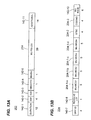
- Figs. 13A and 13B are diagrams of an example bit allocation of the VHT-SIG 202, according to an embodiment.
- the VHT-SIG 202 in MU mode, includes the duration subfield 142-1, the bandwidth subfield 142-2, the SGI subfield 142-3, the smoothing subfield 142-4, the MU/SU subfield 142-6, a plurality of MU subfields 204, and the additional subfields 142-11, such as a CRC subfield and a subfield including tail bits.
- the duration subfield 142-1 the bandwidth subfield 142-2
- the SGI subfield 142-3 the smoothing subfield 142-4
- the MU/SU subfield 142-6 a plurality of MU subfields 204
- the additional subfields 142-11 such as a CRC subfield and a subfield including tail bits.
- the plurality of MU subfields 204 include the group ID subfield 142-7, the resolvable LTF subfield 142-8, a plurality of MU-MCS subfields 204-1, an STBC subfield 204-2, a coding type subfield 204-3, and the MU reserved subfield 142-10.
- the plurality of MU-MCS subfields 204-1 include MU-MCS sub-subfields 204-1-a, 204-1-b, 204-1-c, and 204-1-d, which are denoted MU-MCS 1, MU-MCS2, MU-MCS3, and MU-MCS4, respectively.
- the MU-MCS sub-subfields 204-1-a, 204-1-b, 204-1-c, and 204-1-d each corresponds to one of the client stations 25-1, 25-2, 25-3, and 25-4, according to an embodiment.
- each of the MU-MCS sub-subfields 204-1-a, 204-1-b, 204-1-c, and 204-1-d includes five bits, and indicates a modulation and coding scheme being used for the corresponding client station 25.
- the 32 possible different sequences of five bits one sequence is used to indicate that no data is being transmitted to the corresponding client station 25, in an embodiment. Therefore, any of 31 different MCSs are used for each client station 25, according to an embodiment.
- less than 31 different MCSs may be available for use, and the number of bits allocated to each of the MU-MCS subfields 204-1 is correspondingly reduced.
- the MU-MCS subfields 204-1 are implemented so that they each indicate a number of spatial streams for a respective client station 25, along with an indication of the modulation and coding scheme for the respective client station 25, according to an embodiment.
- the STBC subfield 204-2 also provides an indication of user-specific STBC settings in the VHT-SIG 202.
- the STBC subfield 204-2 includes four bits, where each bit is used to indicate whether STBC is being used for the spatial streams corresponding to a respective one of the client stations 25. Accordingly, the additional usable bits in the VHT-SIG 202 allow user-specific control of both MCSs and STBC settings, in an embodiment.
- the coding type subfield 204-3 is implemented in a manner similar to the STBC subfield 204-2 to allow user-specific control of coding type.
- the MU-MCS subfields 204-1, and the bits within the STBC subfield 204-2 are ordered according to unique index values assigned to the client stations 25 by the AP 14. Therefore, the MU-MCS subfields 204-1 are used together with the STBC subfield 204-2 to provide a complete indication of the number of space-time streams transmitted from the AP 14 to each of the client stations 25.
- Figs. 14A and 14B are diagrams of an example bit allocation of the VHT-SIG 202 in SU mode, according to an embodiment.
- the VHT-SIG 202 includes the duration subfield 142-1, the bandwidth subfield 142-2, the SGI subfield 142-3, the smoothing subfield 142-4, the MU/SU subfield 142-6, a plurality of SU subfields 206, and the additional subfields 142-11, such as a CRC subfield and a subfield including tail bits, in an embodiment.
- the additional subfields 142-11 such as a CRC subfield and a subfield including tail bits, in an embodiment.
- the plurality of SU subfields 206 includes the MCS subfield 152-1, the STBC subfield 142-13, the coding type subfield 152-2, the non-sounding subfield 142-14, the AID subfield 142-15, and an SU reserved subfield 206-1.
- the MU/SU subfield 142-6 is removed in both MU and SU mode, and the VHT-SIG 202 includes the group ID subfield 142-7 in both MU mode and SU mode. Therefore, the group ID subfield 142-7 is set to a reserved bit sequence to indicate that the data unit 200 is an SU data unit, in an embodiment.
- the MCS subfield 152-1, the STBC subfield 142-13, the coding type subfield 152-2, the non-sounding subfield 142-14, and the AID subfield 142-15 are implemented in a similar manner as discussed above with respect to Fig. 9A , for example.
- the SU reserved subfield 206-1 includes bits allocated for implementation of future SU features.
- the AID subfield 142-15 includes more than three bits in order to improve differentiation among client stations, thereby allowing the PHY unit 29 of a client station 25 to more reliably determine that the AID subfield 142-15 does not correspond to the client station 25 (e.g., to an AID of the client station 25) and, in response, shut down for the duration of the data unit 200.
- the SU reserved subfield 206-1 may include fewer than 24 bits when the AID subfield 142-15 includes more than three bits.
- bit savings is achieved, in at least some embodiments, thereby allowing other information, such as more user-specific information in an MU scenario, to be signaled in the VHT-SIG 202.
- the bit savings eliminate the need to implement an LUT in connection with, for example, the Nss subfield 142-9 or the Nsts subfield 142-12. Consequently, processing delay and complexity resulting from searching such an LUT is reduced, in some embodiments.
- Implementation of the PHY unit 29 of each client station 25 also is simplified, in some embodiments, because of the simpler demodulation and decoding attendant to a data unit having a single signal field as opposed to multiple signal fields (e.g., the VHT-SIG1 120 and the VHT-SIG2 135).
- the VHT-SIG 202 allows a single preamble structure to be used for both SU and MU situations, in some embodiments, whereas in some embodiments described above, the VHT-SIG2 135 is used in MU situations but eliminated in SU situations.
- the VHT-SIG 202 also enables each client station 25 to perform more advanced interference mitigation (or "whitening"), because the constellation of interference for the client station 25 is more well-known by virtue of the client station 25 receiving all very high throughput signal field information via the omnidirectional VHT-SIG 202, in an embodiment.
- the VHT-SIG2 135, on the other hand, is beam-steered to different client stations 25 in some embodiments, as discussed above. Consequently, in some embodiments, the VHT-SIG 202 is decoded more reliably than the combination of the VHT-SIG1 120 and the VHT-SIG2 135.
- the VHT-SIG 202 also allows more reserved bits for both MU and SU situations, and therefore better accommodates foreseeable, yet-to-be-developed advanced features, in some embodiments.
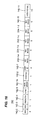
- Fig. 15 is a diagram of yet another data unit 300 that the AP 14 is configured to transmit to the client stations 25 using orthogonal frequency division multiplexing (OFDM) modulation, according to another embodiment.
- One or more of the client stations 25 also are configured to transmit a data unit formatted according to the format of the data unit 300 to the AP 14.
- the data unit 300 conforms to the VHT protocol and occupies an 80 MHz band, in an embodiment. In other embodiments, the data unit 300 occupies a different bandwidth such as discussed with reference the data unit 100.
- the data unit 300 is similar to the data unit 200, but a preamble of the data unit 300 includes four very high throughput signal fields (VHT-SIGs) 302 instead of the VHT-SIG 202.
- VHT-SIGs very high throughput signal fields
- VHT-SIGs 302 are collectively referred to as a single very high throughput signal field (VHT-SIG) 302.
- VHT-SIG 302 has a different format than the VHT-SIG 202, as discussed below.
- the VHT-SIG 302 includes only two OFDM symbols, as compared to three OFDM symbols for the VHT-SIG 202 of Fig. 12 .
- the L-SIGs 115 are used to indicate the duration T of the data unit 300 after the legacy portion by appropriately setting the rate and length subfields in the L-SIGs 115, such as in a manner similar to that described above with respect to Fig. 8 .
- the twelve bits of the duration subfield 142-1 are not included in the VHT-SIG 302, and bits are allocated to the remaining subfields of the VHT-SIG 302 such that only two OFDM symbols are utilized for transmission of the VHT-SIG 302.
- Fig. 16 is a diagram of an example bit allocation for the VHT-SIG 302 in MU mode.
- the VHT-SIG 302 includes the bandwidth subfield 142-2, the SGI subfield 142-3, the smoothing subfield 142-4, the STBC subfield 142-5, the non-sounding subfield 142-14, the coding type subfield 152-2, the group ID subfield 142-7, the MU-MCS subfields 204-1, the MU reserved subfield 142-10, and the additional subfields 142-11.
- the MU-MCS subfields 204-1 are implemented so that they each indicate a number of spatial streams for a respective client station 25, along with an indication of the modulation and coding scheme for the respective client station 25, according to an embodiment.
- the STBC subfield 142-5 indicates an STBC setting that is common to all of the client stations 25, according to an embodiment. Therefore, the MU-MCS subfields 204-1 are used together with the STBC subfield 142-5 to provide a complete indication of the number of space-time streams transmitted from the AP 14 to each of the client stations 25, while using only two OFDM symbols to transmit the entire very high throughput signal content of the preamble.
- Fig. 17 is a diagram of an example bit allocation for the VHT-SIG 302 in SU mode.
- the VHT-SIG 302 includes the bandwidth subfield 142-2, the SGI subfield 142-3, the smoothing subfield 142-4, the STBC subfield 142-5, the non-sounding subfield 142-14, the coding type subfield 152-2, the group ID subfield 142-7, an SU-MCS subfield 304-1, the AID subfield 142-15, the SU reserved subfield 206-1, and the additional subfields 142-11.
- the preamble of the data unit 300 is formatted in substantially the same manner for both SU mode and MU mode, allowing for greater simplicity in the design of the PHY units 29 for the client stations 25.
- the group ID subfield 142-7 is included for both SU mode and MU mode.
- the group ID subfield 142-7 is set to a particular reserved bit sequence, such as the sequence having every bit set to a logic "0", to indicate SU mode, and MU mode is indicated any time the group ID subfield 142-7 differs from the reserved sequence, such as when the group ID subfield 142-7 has one or more bits set to a logic "1".
- the MU/SU subfield 142-6 is included in both MU and SU mode, and the group ID subfield 142-7 is removed in SU mode.
- the SU-MCS subfield 304-1 is implemented such that it indicates a number of spatial streams, along with an indication of a modulation and coding scheme, for a client station to which the data unit 300 is transmitted in SU mode, according to an embodiment.
- the SU-MCS subfield 304-1 is used together with the STBC subfield 142-5 to indicate the number of space-time streams transmitted from the AP 14 to the intended client station.
- the AID subfield 142-15 allows early shut down of the PHY unit 29 of a client station 25 if the PHY unit 29 determines that the client station 25 is not the client station for which the SU transmission is intended, according to an embodiment.
- the AP 14 sends an uplink start indication (USI) frame to the client stations 25.
- the USI frame indicates all of the PHY information for each client station 25 except for user-specific information that each client station 25 includes in a beam-steered very high throughput signal field (e.g., the VHT-SIG2 135), such as an MCS, STBC setting, coding type, etc.
- the client stations 25 do not control any PHY information in UL-MIMO transmissions that is not included in the VHT-SIG2 135 or a similar beam-steered signal field. Instead, any information included in a signal field common to all the client stations 25 (e.g., the VHT-SIG1 120) is required to be controlled by the AP 14, because the AP 14 is better suited to determine conditions of other client stations 25, in an embodiment. For example, the AP 14 may know interference levels across all of the client stations 25, the received signal strength for UL transmissions by each client station 25, the transmit power of each client station 25, etc.
- the AP 14 controls information such as the MCS, STBC setting, etc., which is included in the VHT-SIG 202 or the VHT-SIG 302, for example.
- Fig. 18 is a flow chart of an example method 400 for generating a preamble of a data unit for transmission via a communication channel, according to an embodiment.
- the method 400 will be described with reference to various embodiments of the WLAN 10 and the data units 100, 200, and 300, for ease of explanation. It will be understood, however, that the method 400 is used in networks other than the WLAN 10, and/or is used to generate a preamble of a data unit other than the data units 100, 200, and 300, in some embodiments.
- the PHY unit 20 is configured to perform the method 400, in an embodiment. However, it will be understood that other devices are configured to perform the method 400 in other embodiments.
- the MAC unit 18 is configured to perform at least a portion of the method 400, in an embodiment. It will further be understood that the PHY unit 20 is configured to perform methods other than the method 400, in some embodiments.
- an indication of a first number of spatial or space-time streams is included in a first field of the preamble.
- the indication of the first number of streams corresponds to transmission of the data unit to a first receiver, e.g., the client station 25-1.
- the first field of the preamble is the VHT-SIG1 120, in one embodiment.
- the first field is the VHT-SIG 202.
- the first field is the VHT-SIG 302.
- one or more training sequences are included in a second field of the preamble.
- the indication of the first number of streams indicates that a first set of the one or more training sequences in the second field, e.g., a first set of the VHT-LTFs 130, corresponds to the first receiver.
- the preamble is formatted such that the first field of the preamble will be transmitted prior to the second field of the preamble being transmitted. Accordingly, the client station 25-1 receives the indication of the first number of spatial or space-time streams, and therefore the indication that the first set of the VHT-LTFs 130 corresponds to the client station 25-1, before receiving the VHT-LTFs 130, according to an embodiment.
- one or more features shown in Fig. 18 are not performed, and/or one or more additional features not shown in Fig. 18 are performed.
- the order shown in Fig. 18 does not indicate the order in which the method 400 is performed, and/or does not indicate that each block is completed before another block begins.
- Fig. 19 is a flow chart of an example method 500 for receiving a preamble of a data unit via a communication channel using a first receiver, according to an embodiment.
- the method 500 will be described with reference to various embodiments of the WLAN 10 and the data units 100, 200, and 300, for ease of explanation. It will be understood, however, that the method 500 is used in networks other than the WLAN 10, and/or is used to receive a preamble of a data unit other than the data units 100, 200, and 300, in some embodiments.
- the PHY unit 29 is configured to perform the method 500, in an embodiment. However, it will be understood that other devices are configured to perform the method 500 in other embodiments. It will further be understood that the PHY unit 29 is configured to perform methods other than the method 500, in some embodiments.
- a first field of the preamble is received.
- the first field includes an indication of a first number of spatial or space-time streams of the data unit which correspond to the first receiver, e.g., the client station 25-1.
- a first set of one or more training sequences in a second field of the preamble corresponds to the first receiver. Accordingly, upon receiving the second field of the preamble, the client station 25-1 already knows which ones of the VHT-LTFs 130 correspond to the client station 25-1, according to an embodiment.
- the determination at block 504 is made in any of various suitable ways, such as in one of the example ways described above, according to various embodiments.
- the one or more training sequences of the second field of the preamble are received.
- the first set of the one or more training sequences is utilized to generate an estimate of at least a portion of the communication channel.
- at least a portion of block 508 is performed while performing block 506. Accordingly, the method 500 allows the communication channel to be estimated earlier by virtue of providing a way to determine that the first set of the one or more training sequences corresponds to the first receiver, before receiving the one or more training sequences, in an embodiment.
- one or more features shown in Fig. 19 are not performed, and/or one or more additional features not shown in Fig. 19 are performed.
- the order shown in Fig. 19 does not indicate the order in which the method 500 is performed, and/or does not indicate that each block is completed before another block begins.
- Fig. 20 is a flow chart of an example method 600 for generating a preamble of a data unit for transmission via a multi-user MIMO (MU-MIMO) communication channel, according to an embodiment.
- the method 600 will be described with reference to various embodiments of the WLAN 10 and the data units 100, 200, and 300, for ease of explanation. It will be understood, however, that the method 600 is used in networks other than the WLAN 10, and/or is used to generate a preamble of a data unit other than the data units 100, 200, and 300, in some embodiments.
- the PHY unit 20 is configured to perform the method 600, in an embodiment. However, it will be understood that other devices are configured to perform the method 600 in other embodiments.
- the MAC unit 18 is configured to perform at least a portion of the method 600, in an embodiment. It will further be understood that the PHY unit 20 is configured to perform methods other than the method 600, in some embodiments.
- a first field of the preamble is generated.
- the first field of the preamble provides a plurality of indicators to a plurality of receivers.
- each indicator corresponds to one of the plurality of receivers, and each indicator indicates a set of a plurality of training sequences that corresponds to transmission of the data unit to the corresponding receiver.
- the first field of the preamble provides an indicator to the client station 25-1 of a first set of the plurality of training sequences that corresponds to transmission of the data unit to the client station 25-1, in an embodiment.
- the first field of the preamble further provides an indication to the client station 25-2 of a second set of the plurality of training sequences that corresponds to transmission of the data unit to the client station 25-2, in an embodiment, and/or provides corresponding indicators of sets of the plurality of training sequences to the client stations 25-3, 25-4, etc., in some embodiments.
- At least one of the indicators provided to the plurality of receivers includes an indication of a number of spatial streams corresponding to transmission of the data unit to the receiver; an indication of a number of space-time streams corresponding to transmission of the data unit to the receiver; an indication of a number of training fields corresponding to transmission of the data unit to the receiver; or any suitable indication of a position of a set of training sequences within, for example, the VHT-LTFs 130.
- at least one of the indicators provided to one of the plurality of receivers is a further indicator of the set of the plurality of training sequences that corresponds to transmission of the data unit to another one of the plurality of receivers.
- a second one of the plurality of receivers uses the indicator of the set of the plurality of training sequences that corresponds to transmission of the data unit to a first one of the plurality of receivers as a further indicator (i.e., in addition to the indicator that corresponds to the second receiver) of the set of the plurality of training sequences that corresponds to transmission of the data unit to the second receiver, in an embodiment.
- an indication of the number of spatial or space-time streams that corresponds to transmission of the data unit to the second receiver is an indicator of the set of the plurality of training sequences that corresponds to transmission of the data unit to the second receiver.
- an indication of the number of spatial or space-time streams that corresponds to transmission of the data unit to the first receiver is a further indicator of the set of the plurality of training sequences that corresponds to transmission of the data unit to the second receiver.
- Unique index values are used to indicate the order in which the plurality of indicators of the sets of the plurality of training sequences will be provided to the plurality of receivers, in some embodiments.
- each unique index value corresponds to one of the plurality of receivers, in an embodiment.
- the unique index value corresponding to the client station 25-1 indicates the position or order of a subfield of the first field of the preamble, relative to other subfields of the first field of the preamble, which corresponds to the client station 25-1.
- the subfield which corresponds to the client station 25-1 includes an indication of a number of spatial or space-time streams corresponding to transmission of the data unit to the client station 25-1, or another suitable indication of the set of the plurality of training sequences which corresponds to the client station 25-1, according to an embodiment.
- Other unique index values may be used in similar ways for other ones of the plurality of receivers, such as the client station 25-2, the client station 25-3, etc.. The unique index values are therefore used to indicate the locations of sets of the plurality of training sequences within the VHT-LTFs 130, according to an embodiment.
- the plurality of training sequences is included in a second field of the preamble.
- the preamble is formatted such that the first field of the preamble will be transmitted prior to the second field of the preamble being transmitted. Accordingly, each of the plurality of receivers receives an indication of a set of the plurality of training sequences that corresponds to transmission of the data unit to the receiver before receiving the VHT-LTFs 130, according to an embodiment.
- one or more features shown in Fig. 20 are not performed, and/or one or more additional features not shown in Fig. 20 are performed.
- the order shown in Fig. 20 does not indicate the order in which the method 600 is performed, and/or does not indicate that each block is completed before another block begins.
- Fig. 21 is a flow chart of an example method 700 for receiving a preamble of a data unit via a multi-user MIMO (MU-MIMO) communication channel using a first receiver, such as using the PHY unit 29 of the client station 25-1, according to an embodiment.
- the method 700 will be described with reference to various embodiments of the WLAN 10 and the data units 100, 200, and 300, for ease of explanation. It will be understood, however, that the method 700 is used in networks other than the WLAN 10, and/or is used to receive a preamble of a data unit other than the data units 100, 200, and 300, in some embodiments.
- the PHY unit 29 is configured to perform the method 700, in an embodiment. However, it will be understood that other devices are configured to perform the method 700 in other embodiments. It will further be understood that the PHY unit 29 is configured to perform methods other than the method 700, in some embodiments.
- a first field of the preamble is received.
- the first field provides a plurality of indicators to a plurality of receivers.
- the plurality of receivers includes the first receiver, e.g., the client station 25-1, in an embodiment.
- each indicator corresponds to one of the plurality of receivers, and each indicator indicates a set of a plurality of training sequences that corresponds to transmission of the data unit to the corresponding receiver.
- the first field of the preamble provides an indicator to the client station 25-1 of a first set of the plurality of training sequences that corresponds to transmission of the data unit to the client station 25-1, in an embodiment.
- the first field of the preamble further provides an indicator to the client station 25-2 of a second set of the plurality of training sequences that corresponds to transmission of the data unit to the client station 25-2, in an embodiment, and/or provides corresponding indicators of sets of the plurality of training sequences to the client stations 25-3, 25-4, etc., in some embodiments.
- the indicator that corresponds to the first receiver includes an indication of a number of spatial streams corresponding to transmission of the data unit to the first receiver; an indication of a number of space-time streams corresponding to transmission of the data unit to the first receiver; an indication of a number of training fields corresponding to transmission of the data unit to the first receiver; or any suitable indication of a position of a set of training sequences within, for example, the VHT-LTFs 130, that corresponds to transmission of the data unit to the first receiver.
- a second one of the plurality of indicators that corresponds to a second one of the plurality of receivers is a further indicator of the set of the plurality of training sequences that corresponds to transmission of the data unit to the first receiver, in addition to the indicator that corresponds to the first receiver.
- an indication of the number of spatial or space-time streams that corresponds to transmission of the data unit to the first receiver is an indicator of the set of the plurality of training sequences that corresponds to transmission of the data unit to the first receiver.
- an indication of the number of spatial or space-time streams that corresponds to transmission of the data unit to the second receiver is a further indicator of the set of the plurality of training sequences that corresponds to transmission of the data unit to the first receiver.
- unique index values are used to indicate the order in which the plurality of indicators of the sets of the plurality of training sequences will be provided to the plurality of receivers, in some embodiments.
- each unique index value corresponds to one of the plurality of receivers, in an embodiment.
- the unique index value corresponding to the client station 25-1 indicates the position or order of a subfield of the first field of the preamble, relative to other subfields of the first field of the preamble, which corresponds to the client station 25-1.
- the subfield which corresponds to the client station 25-1 includes an indication of a number of spatial or space-time streams corresponding to transmission of the data unit to the client station 25-1, or another suitable indication of the set of the plurality of training sequences which corresponds to the client station 25-1, according to an embodiment.
- Other unique index values may be used in similar ways for other ones of the plurality of receivers, such as the client station 25-2, the client station 25-3, etc.
- the client station 25-1 therefore receives its unique index value and uses its unique index value to determine the location of the set of the plurality of training sequences within the VHT-LTFs 130 that corresponds to the client station 25-1, as described above, according to an embodiment.
- the determination at block 704 is made in any of various suitable ways, such as in one of the example ways described above, according to various embodiments. In some embodiments, where a second one of the plurality of indicators that corresponds to a second one of the plurality of receivers is a further indicator of the set of the plurality of training sequences that corresponds to transmission of the data unit to the first receiver, the determination at block 704 is made further based on the second one of the plurality of indicators.
- a second field of the preamble is received.
- the second field of the preamble includes the plurality of training sequences. Therefore, based on the result of block 704, the client station 25-1 already knows, upon receiving at least some of the VHT-LTFs 130, which ones of the VHT-LTFs 130 correspond to the client station 25-1, according to an embodiment.
- the first set of training sequences is utilized to generate an estimate of at least a portion of the communication channel between a transmitter, such as the AP 14, and the first receiver, such as the client station 25-1.
- at least a portion of block 708 is performed while performing block 706. Accordingly, the method 700 allows the communication channel to be estimated earlier by virtue of providing a way to determine that the first set of training sequences corresponds to the first receiver, before receiving at least some of the training sequences, in an embodiment.
- one or more features shown in Fig. 21 are not performed, and/or one or more additional features not shown in Fig. 21 are performed.
- the order shown in Fig. 21 does not indicate the order in which the method 700 is performed, and/or does not indicate that each block is completed before another block begins.
- the various blocks, operations, and techniques described above may be implemented utilizing hardware, a processor executing firmware instructions, a processor executing software instructions, or any combination thereof.
- the software or firmware instructions may be stored in any computer readable memory such as on a magnetic disk, an optical disk, or other storage medium, in a RAM or ROM or flash memory, processor, hard disk drive, optical disk drive, tape drive, etc.
- the software or firmware instructions may be delivered to a user or a system via any known or desired delivery method including, for example, on a computer readable disk or other transportable computer storage mechanism or via communication media.
- Communication media typically embodies computer readable instructions, data structures, program modules or other data in a modulated data signal such as a carrier wave or other transport mechanism.
- modulated data signal means a signal that has one or more of its characteristics set or changed in such a manner as to encode information in the signal.
- communication media includes wired media such as a wired network or direct-wired connection, and wireless media such as acoustic, radio frequency, infrared and other wireless media.
- the software or firmware instructions may be delivered to a user or a system via a communication channel such as a telephone line, a DSL line, a cable television line, a fiber optics line, a wireless communication channel, the Internet, etc. (which are viewed as being the same as or interchangeable with providing such software via a transportable storage medium).
- the software or firmware instructions may include machine readable instructions that, when executed by the processor, cause the processor to perform various acts.
- the hardware may comprise one or more of discrete components, an integrated circuit, an application-specific integrated circuit (ASIC), etc.
- ASIC application-specific integrated circuit
Applications Claiming Priority (8)
| Application Number | Priority Date | Filing Date | Title |
|---|---|---|---|
| US25460809P | 2009-10-23 | 2009-10-23 | |
| US25503809P | 2009-10-26 | 2009-10-26 | |
| US25958409P | 2009-11-09 | 2009-11-09 | |
| US26072909P | 2009-11-12 | 2009-11-12 | |
| US29472910P | 2010-01-13 | 2010-01-13 | |
| US30778010P | 2010-02-24 | 2010-02-24 | |
| US32139010P | 2010-04-06 | 2010-04-06 | |
| PCT/US2010/053849 WO2011050324A1 (en) | 2009-10-23 | 2010-10-22 | Training sequence indication for wlan |
Publications (2)
| Publication Number | Publication Date |
|---|---|
| EP2491663A1 EP2491663A1 (en) | 2012-08-29 |
| EP2491663B1 true EP2491663B1 (en) | 2015-07-29 |
Family
ID=43432237
Family Applications (2)
| Application Number | Title | Priority Date | Filing Date |
|---|---|---|---|
| EP10776467.2A Active EP2491662B1 (en) | 2009-10-23 | 2010-10-22 | Number of streams indication for WLAN |
| EP10776468.0A Active EP2491663B1 (en) | 2009-10-23 | 2010-10-22 | Training sequence indication for WLAN |
Family Applications Before (1)
| Application Number | Title | Priority Date | Filing Date |
|---|---|---|---|
| EP10776467.2A Active EP2491662B1 (en) | 2009-10-23 | 2010-10-22 | Number of streams indication for WLAN |
Country Status (6)
| Country | Link |
|---|---|
| US (5) | US9294164B2 (ko) |
| EP (2) | EP2491662B1 (ko) |
| JP (2) | JP5718346B2 (ko) |
| KR (2) | KR101783927B1 (ko) |
| CN (2) | CN102577161B (ko) |
| WO (2) | WO2011050324A1 (ko) |
Families Citing this family (149)
| Publication number | Priority date | Publication date | Assignee | Title |
|---|---|---|---|---|
| CN101755498B (zh) | 2007-07-18 | 2016-09-28 | 马维尔国际贸易有限公司 | 一种无线网络和客户站 |
| JP5350380B2 (ja) | 2007-07-18 | 2013-11-27 | マーベル ワールド トレード リミテッド | 複数のクライアント局に対する独立したデータを同時ダウンリンク伝送するアクセスポイント |
| US8982889B2 (en) | 2008-07-18 | 2015-03-17 | Marvell World Trade Ltd. | Preamble designs for sub-1GHz frequency bands |
| US9924512B1 (en) | 2009-03-24 | 2018-03-20 | Marvell International Ltd. | OFDMA with block tone assignment for WLAN |
| US8599803B1 (en) | 2009-05-01 | 2013-12-03 | Marvell International Ltd. | Open loop multiple access for WLAN |
| US8571010B1 (en) | 2009-07-21 | 2013-10-29 | Marvell International Ltd. | Simultaneous uplink transmission in a wireless network |
| US9706599B1 (en) | 2009-07-23 | 2017-07-11 | Marvell International Ltd. | Long wireless local area network (WLAN) packets with midambles |
| US8837524B2 (en) | 2011-08-29 | 2014-09-16 | Marvell World Trade Ltd. | Coexistence of a normal-rate physical layer and a low-rate physical layer in a wireless network |
| US9077594B2 (en) | 2009-07-23 | 2015-07-07 | Marvell International Ltd. | Coexistence of a normal-rate physical layer and a low-rate physical layer in a wireless network |
| WO2011014685A2 (en) | 2009-07-29 | 2011-02-03 | Marvell World Trade Ltd. | Methods and apparatus for wlan transmission |
| US9042331B2 (en) | 2009-09-09 | 2015-05-26 | Lg Electronics Inc. | Method and apparatus for transmitting control information in WLAN system |
| EP2491662B1 (en) | 2009-10-23 | 2015-07-29 | Marvell World Trade Ltd. | Number of streams indication for WLAN |
| EP3107329B1 (en) * | 2009-10-30 | 2020-05-06 | Electronics and Telecommunications Research Institute | Method for transmitting control and training symbols in multi-user wireless communication system |
| JP5718350B2 (ja) | 2009-11-03 | 2015-05-13 | マーベル ワールド トレード リミテッド | 通信デバイスでの省電力 |
| US8325644B2 (en) * | 2009-11-06 | 2012-12-04 | Qualcomm Incorporated | Mixed mode preamble design for signaling number of streams per client |
| CN102598769B (zh) * | 2009-11-12 | 2015-07-22 | 交互数字专利控股公司 | 提供用于无线通信的甚高吞吐量操作和能力信令的方法和设备 |
| CN102771060B (zh) * | 2009-11-24 | 2016-05-18 | 韩国电子通信研究院 | 用于在基于多用户多输入多输出的无线通信系统中恢复传送失败的帧的方法 |
| KR101948082B1 (ko) | 2009-11-24 | 2019-04-25 | 한국전자통신연구원 | 다중 사용자 다중 안테나 기반 무선통신 시스템에서 데이터 보호 방법 |
| US8472383B1 (en) | 2009-11-24 | 2013-06-25 | Marvell International Ltd. | Group management in multiuser communications |
| EP2507929B1 (en) * | 2009-12-02 | 2022-08-10 | Marvell Asia Pte, Ltd. | Method and apparatus for sounding multiple stations |
| KR101559295B1 (ko) * | 2009-12-04 | 2015-10-12 | 삼성전자주식회사 | 공간 분할 다중 사용자 다중 입력 다중 출력 방식을 이용하는 통신 시스템 |
| US8886755B1 (en) | 2009-12-09 | 2014-11-11 | Marvell International Ltd. | Method and apparatus for facilitating simultaneous transmission from multiple stations |
| JP5744895B2 (ja) | 2009-12-10 | 2015-07-08 | エルジー エレクトロニクス インコーポレイティド | 無線lanシステムにおけるトレーニング信号送信方法及び装置 |
| US8681679B2 (en) | 2009-12-21 | 2014-03-25 | Lg Electronics Inc. | Transmitting system and method for transmitting digital broadcast signal |
| KR20110082685A (ko) * | 2010-01-12 | 2011-07-20 | 삼성전자주식회사 | 다중 사용자 다중 입출력 시스템의 프리엠블 생성 방법 및 상기 방법이 채용된 데이터 전송 장치와 단말 |
| KR101341192B1 (ko) * | 2010-02-09 | 2013-12-12 | 엘지전자 주식회사 | 무선 랜에서 채널 접근 방법 및 장치 |
| US8718173B2 (en) | 2010-02-12 | 2014-05-06 | Lg Electronics Inc. | Method for transmitting control information and apparatus for the same |
| KR101801943B1 (ko) * | 2010-02-25 | 2017-11-27 | 한국전자통신연구원 | 다중 사용자 다중 안테나 기반 무선 통신 시스템에서 훈련 시퀀스 전송 방법 및 그 장치 |
| EP2547002B1 (en) | 2010-03-12 | 2015-02-25 | Electronics and Telecommunications Research Institute | Method and apparatus for transmitting and receiving data in a mimo system |
| US8855067B2 (en) * | 2010-04-02 | 2014-10-07 | Marvell World Trade Ltd. | Multi-user communication group management and signaling |
| US9397785B1 (en) | 2010-04-12 | 2016-07-19 | Marvell International Ltd. | Error detection in a signal field of a WLAN frame header |
| TWI552635B (zh) * | 2010-04-13 | 2016-10-01 | 內數位專利控股公司 | 在無線區域網路中群傳輸 |
| WO2011149271A2 (ko) | 2010-05-26 | 2011-12-01 | 엘지전자 주식회사 | 무선랜 시스템에서 파워 세이브 모드 운영 방법 및 장치 |
| WO2011159800A1 (en) | 2010-06-16 | 2011-12-22 | Marvell World Trade Ltd. | Alternate feedback types for downlink multiple user mimo configurations |
| WO2012002758A2 (ko) * | 2010-07-01 | 2012-01-05 | 엘지전자 주식회사 | 무선랜 시스템에서 mimo 패킷을 송수신하는 방법 및 장치 |
| US20120002622A1 (en) * | 2010-07-02 | 2012-01-05 | Ralink Technology (Singapore) Corporation Pte. Ltd. | Method for signal space partition and assignment and apparatus using the same |
| US9094175B2 (en) * | 2010-07-16 | 2015-07-28 | Qualcomm, Incorporated | Method and apparatus for saving power by using signal field of preamble |
| US9860037B2 (en) | 2010-07-21 | 2018-01-02 | Qualcomm, Incorporated | Method and apparatus for ordering sub-fields of VHT-SIG-A and VIT-SIG-B fields |
| JP6002974B2 (ja) | 2010-08-10 | 2016-10-05 | マーベル ワールド トレード リミテッド | ダウンリンクマルチユーザmimo構成におけるビームフォーミングのためのサブバンドフィードバック |
| US9054929B2 (en) | 2010-08-11 | 2015-06-09 | Qualcomm Incorporated | Constructing very high throughput signal (VHT-SIG) fields for reduced peak-to-average power ratio (PAPR) |
| KR101527120B1 (ko) | 2010-08-17 | 2015-06-08 | 삼성전자주식회사 | 멀티 유저의 txop 파워 세이빙을 위한 액티브 모드에서의 단말 및 액세스 포인트의 통신 방법 |
| US8494075B2 (en) | 2010-08-26 | 2013-07-23 | Qualcomm Incorporated | Single stream phase tracking during channel estimation in a very high throughput wireless MIMO communication system |
| US9509391B2 (en) | 2010-09-08 | 2016-11-29 | Qualcomm Incorporated | Sounding feedback schemes for very high throughput wireless systems |
| US8553605B2 (en) * | 2010-09-10 | 2013-10-08 | Qualcomm Incorporated | Packet identification for power saving in wireless communication networks |
| US8989213B2 (en) * | 2010-09-15 | 2015-03-24 | Qualcomm Incorporated | Physical layer header with access point identifier |
| US9247541B2 (en) * | 2010-09-16 | 2016-01-26 | Qualcomm Incorporated | Selecting frequency bands for transmitting data packets |
| US9749090B2 (en) * | 2010-09-16 | 2017-08-29 | Qualcomm Incorporated | System and method for transmitting a low density parity check signal |
| US8340601B2 (en) * | 2010-09-20 | 2012-12-25 | Intel Corporation | MU MIMO support with highly directional antennas |
| WO2012054694A1 (en) * | 2010-10-21 | 2012-04-26 | Mediatek Singapore Pte. Ltd. | Integrity and quality monitoring and signaling for sounding and reduced feedback |
| US11152977B2 (en) | 2010-10-21 | 2021-10-19 | Mediatek Singapore Pte. Ltd. | Integrity and quality monitoring and signaling for sounding and reduced feedback |
| US8615023B2 (en) * | 2010-10-27 | 2013-12-24 | Electronics And Telecommunications Research Institute | Apparatus and method for transmitting/receiving data in communication system |
| JP5690850B2 (ja) * | 2010-11-26 | 2015-03-25 | エルジー エレクトロニクス インコーポレイティド | 無線lanシステムではリンク適応に基づいて、チャネル情報を報告する方法とそれをサポートするデバイス |
| US9014105B2 (en) * | 2010-11-30 | 2015-04-21 | Stmicroelectronics, Inc. | 80MHZ/160MHZ transmission opportunity (TXOP) protection in 802.11ac transmissions |
| US8934466B2 (en) * | 2010-12-16 | 2015-01-13 | Qualcomm Incorporated | Method and apparatus for supporting modulation-coding scheme set in very high throughput wireless systems |
| US8982812B2 (en) | 2011-01-14 | 2015-03-17 | Qualcomm Incorporated | Group ID allocation for direct link service (DLS) |
| WO2012106635A1 (en) | 2011-02-04 | 2012-08-09 | Marvell World Trade Ltd. | Control mode phy for wlan |
| KR101760333B1 (ko) * | 2011-03-02 | 2017-07-21 | 삼성전자주식회사 | 다중 사용자 다중 안테나 전송에서 그룹 아이디 관리를 위한 타겟 단말 및 액세스 포인트의 통신 방법 |
| WO2012148487A1 (en) * | 2011-04-26 | 2012-11-01 | Intel Corporation | Methods and arrangements for low power wireless networks |
| US8934413B2 (en) * | 2011-05-13 | 2015-01-13 | Qualcomm Incorporated | Systems and methods for wireless communication of packets having a plurality of formats |
| US9154363B2 (en) * | 2011-05-13 | 2015-10-06 | Qualcomm Incorporated | Systems and methods for wireless communication of packets having a plurality of formats |
| US8824371B2 (en) * | 2011-05-13 | 2014-09-02 | Qualcomm Incorporated | Systems and methods for wireless communication of packets having a plurality of formats |
| US9385911B2 (en) | 2011-05-13 | 2016-07-05 | Sameer Vermani | Systems and methods for wireless communication of packets having a plurality of formats |
| US8891435B2 (en) * | 2011-06-15 | 2014-11-18 | Marvell World Trade Ltd. | Low bandwidth PHY for WLAN |
| DE112012002426T5 (de) * | 2011-06-15 | 2014-02-27 | Lg Electronics Inc. | Verfahren zum Senden und Empfangen einer Dateneinheit auf der Grundlage einer Mehrfacheingabe/Mehrfachausgabesendung mit mehreren Benutzern im Uplink und eine Vorrichtung hierfür |
| CN104270224B (zh) * | 2011-06-24 | 2018-01-02 | 华为技术有限公司 | 链路自适应反馈方法和发送端设备 |
| EP4221045A1 (en) * | 2011-06-24 | 2023-08-02 | InterDigital Patent Holdings, Inc. | Method and apparatus for receiving a preamble in a wireless communication system |
| WO2013025923A1 (en) * | 2011-08-18 | 2013-02-21 | Marvell World Trade Ltd. | Signal field design for wlan |
| US9100275B2 (en) * | 2011-09-06 | 2015-08-04 | Sameer Vermani | Signal unit including a field indicative of a zero-length payload |
| CN103001682B (zh) | 2011-09-14 | 2015-03-11 | 华为技术有限公司 | 一种数据反馈方法以及相关装置 |
| US8599735B2 (en) * | 2011-09-14 | 2013-12-03 | Cisco Technology, Inc. | Group addressing for multicast transmissions for power savings at physical layer |
| CN103002504B (zh) * | 2011-09-16 | 2017-10-10 | 华为技术有限公司 | 数据发送方法及接入点、数据接收方法及站点、系统 |
| CN103002448B (zh) * | 2011-09-19 | 2018-04-17 | 工业和信息化部电信传输研究所 | 一种无线局域网信道配置方法及装置 |
| US8761234B2 (en) * | 2011-10-25 | 2014-06-24 | Qualcomm Incorporated | Rate selection for frames in wireless devices |
| KR101945974B1 (ko) * | 2011-11-02 | 2019-02-11 | 마벨 월드 트레이드 리미티드 | 무선 근거리 통신망(wlan)에서 데이터 유닛의 물리 계층(phy) 모드를 자동으로 검출하는 방법 및 장치 |
| EP2782274A4 (en) * | 2011-11-18 | 2015-12-23 | Lg Electronics Inc | METHOD FOR TRANSMITTING DATA UNIT IN WIRELESS LOCAL NETWORK SYSTEM AND APPARATUS SUPPORTING THE SAME |
| US9379868B2 (en) * | 2011-12-05 | 2016-06-28 | Broadcom Corporation | Subsequent association identifier (AID) update within single user, multiple user, multiple access, and/or MIMO wireless communications |
| US9071489B2 (en) * | 2011-12-07 | 2015-06-30 | Futurewei Technologies, Inc. | System and method for preambles in a wireless communications network |
| EP3557830A1 (en) | 2012-01-13 | 2019-10-23 | Marvell World Trade Ltd. | Data unit format for single user beamforming in long-range wireless local area networks (wlans) |
| EP2810417B1 (en) | 2012-01-30 | 2020-03-11 | Marvell World Trade Ltd. | Systems and methods for generating preamble symbols in communication systems |
| US9001930B2 (en) | 2012-02-21 | 2015-04-07 | Futurewei Technologies, Inc. | Dual-stream signal (SIG) field encoding with higher order modulation |
| US9179496B2 (en) * | 2012-04-02 | 2015-11-03 | Qualcomm Incorporated | Tone scaling parameters in Sub-1 GHz networks |
| US9100947B2 (en) * | 2012-04-02 | 2015-08-04 | Qualcomm Incorporated | Modulation and coding schemes in sub-1 GHz networks |
| CN104247316B (zh) | 2012-04-03 | 2018-10-02 | 马维尔国际贸易有限公司 | 用于wlan的物理层帧格式 |
| WO2013165582A1 (en) * | 2012-04-30 | 2013-11-07 | Interdigital Patent Holdings, Inc. | Method and apparatus for supporting coordinated orthogonal block-based resource allocation (cobra) operations |
| US9246729B2 (en) * | 2012-08-03 | 2016-01-26 | Marvell World Trade Ltd. | Multi-mode indication in subfield in a signal field of a wireless local area network data unit |
| EP2959309B1 (en) * | 2013-02-19 | 2019-05-15 | Intel IP Corporation | Improved wireless network location techniques |
| US9414432B2 (en) | 2013-04-03 | 2016-08-09 | Marvell World Trade Ltd. | Physical layer frame format for WLAN |
| US9398123B2 (en) * | 2013-05-03 | 2016-07-19 | Qualcomm Incorporated | Systems and methods for aggregation of physical protocol data units on a wireless network |
| EP3547630A1 (en) * | 2013-06-27 | 2019-10-02 | Huawei Technologies Co., Ltd. | Data transmission method and apparatus |
| CN105284082B (zh) * | 2013-06-27 | 2019-02-26 | 华为技术有限公司 | 传输数据的方法和装置 |
| US10038996B1 (en) | 2013-07-09 | 2018-07-31 | Marvell International Ltd. | User group selection in multiple user multiple input multiple output (MU-MIMO) configurations |
| JP6253784B2 (ja) * | 2013-09-10 | 2017-12-27 | マーベル ワールド トレード リミテッド | 屋外wlanのための拡張ガードインターバル |
| US8867642B1 (en) * | 2013-09-30 | 2014-10-21 | Communication Systems LLC | Apparatuses, methods, and computer program products for communication |
| EP3061219B1 (en) | 2013-10-25 | 2020-04-08 | Marvell World Trade Ltd. | Range extension mode for wifi |
| US10218822B2 (en) | 2013-10-25 | 2019-02-26 | Marvell World Trade Ltd. | Physical layer frame format for WLAN |
| US10194006B2 (en) | 2013-10-25 | 2019-01-29 | Marvell World Trade Ltd. | Physical layer frame format for WLAN |
| US9825678B2 (en) | 2013-11-26 | 2017-11-21 | Marvell World Trade Ltd. | Uplink multi-user multiple input multiple output for wireless local area network |
| US9166660B2 (en) | 2013-11-27 | 2015-10-20 | Marvell World Trade Ltd. | Uplink multi-user multiple input multiple output beamforming |
| US9473341B2 (en) | 2013-11-27 | 2016-10-18 | Marvell World Trade Ltd. | Sounding and tone block allocation for orthogonal frequency multiple access (OFDMA) in wireless local area networks |
| WO2015081288A1 (en) | 2013-11-27 | 2015-06-04 | Marvell Semiconductor, Inc. | Medium access protection and bandwidth negotiation in a wireless local area network |
| JP6508838B2 (ja) | 2013-11-27 | 2019-05-08 | マーベル ワールド トレード リミテッド | 無線ローカルエリアネットワークのための直交周波数分割多元接続 |
| GB2521480B (en) * | 2013-12-23 | 2016-05-25 | Ip Access Ltd | Method and device for managing radio access points |
| DE102015017324B4 (de) * | 2014-03-06 | 2023-12-21 | Apple Inc. | Wi-Fi-Präambel-Feld niedriger Energie |
| US9681386B2 (en) | 2014-03-06 | 2017-06-13 | Apple Inc. | Wi-Fi low energy preamble |
| US9935794B1 (en) | 2014-03-24 | 2018-04-03 | Marvell International Ltd. | Carrier frequency offset estimation |
| WO2015166959A1 (ja) * | 2014-04-28 | 2015-11-05 | 株式会社 東芝 | 通信制御装置、無線端末、メモリーカード、集積回路、無線通信装置および無線通信方法 |
| US11855818B1 (en) | 2014-04-30 | 2023-12-26 | Marvell Asia Pte Ltd | Adaptive orthogonal frequency division multiplexing (OFDM) numerology in a wireless communication network |
| KR20160148687A (ko) | 2014-05-02 | 2016-12-26 | 마벨 월드 트레이드 리미티드 | 무선 통신 네트워크에서의 다중 사용자 할당 시그널링 |
| US10164695B2 (en) | 2014-05-09 | 2018-12-25 | Marvell World Trade Ltd. | Tone block and spatial stream allocation |
| US9596060B1 (en) | 2014-05-09 | 2017-03-14 | Marvell International Ltd. | Tone block allocation for orthogonal frequency division multiple access data unit |
| US9584195B2 (en) * | 2014-06-02 | 2017-02-28 | Intel IP Corporation | MIMO and bandwidth signaling in millimeter-wave systems |
| US9832059B2 (en) | 2014-06-02 | 2017-11-28 | Marvell World Trade Ltd. | High efficiency orthogonal frequency division multiplexing (OFDM) physical layer (PHY) |
| US9954703B2 (en) | 2014-06-11 | 2018-04-24 | Marvell World Trade Ltd. | Compressed preamble for a wireless communication system |
| WO2015198140A1 (en) * | 2014-06-27 | 2015-12-30 | Techflux, Ltd. | Detecting format of data |
| KR20160022791A (ko) * | 2014-08-20 | 2016-03-02 | 뉴라컴 인코포레이티드 | 고효율 무선랜에서 공간 시간 블록 코딩이 적용된 물리계층 프로토콜 데이터 유닛 포맷 |
| KR101938100B1 (ko) * | 2014-09-29 | 2019-01-11 | 후아웨이 테크놀러지 컴퍼니 리미티드 | 채널 추정 방법, 통신 노드 및 통신 시스템 |
| US20160105261A1 (en) * | 2014-10-09 | 2016-04-14 | Huawei Technologies Co., Ltd. | System and Method for Space-Time Block Coded Communications |
| BR112017008123B1 (pt) | 2014-10-20 | 2023-11-14 | Huawei Technologies Co., Ltd | Método e aparelho para enviar e receber sinalização em rede de área local sem fio |
| CN111212012B (zh) * | 2014-10-31 | 2021-11-09 | 华为技术有限公司 | 一种网络设备、终端和数据传输方法 |
| JP6433260B2 (ja) | 2014-11-19 | 2018-12-05 | パナソニック株式会社 | ワイヤレス通信システムにおける空間共有の方法 |
| US11317260B2 (en) * | 2015-01-27 | 2022-04-26 | Telefonaktiebolaget Lm Ericsson (Publ) | Methods and arrangements for WLAN communication of multi-user data in a single data packet |
| WO2016126077A2 (ko) * | 2015-02-02 | 2016-08-11 | 주식회사 윌러스표준기술연구소 | 트레이닝 신호를 이용하는 무선 통신 방법 및 무선 통신 단말 |
| CN111970098B (zh) * | 2015-02-17 | 2023-11-10 | 韦勒斯标准与技术协会公司 | 无线通信终端和无线通信方法 |
| US10153857B1 (en) | 2015-04-10 | 2018-12-11 | Marvell International Ltd. | Orthogonal frequency division multiple access protection |
| WO2016173103A1 (zh) | 2015-04-30 | 2016-11-03 | 华为技术有限公司 | Wlan系统的资源指示方法及装置 |
| HUE056887T2 (hu) | 2015-05-05 | 2022-03-28 | Huawei Tech Co Ltd | Eljárás és berendezés fizikai réteg protokoll adategység átvitelére |
| EP3304795B1 (en) * | 2015-05-27 | 2020-03-04 | NXP USA, Inc. | Signaling resource allocations in multi-user data units |
| DE112016003210B4 (de) | 2015-07-16 | 2021-05-27 | Communication Systems LLC | Einrichtungen, verfahren und computerlesbares medium zur kommunikation in einem drahtlosen lokalen netzwerk |
| US10045349B2 (en) | 2015-07-16 | 2018-08-07 | Ali Atefi | Apparatuses, methods, and computer-readable medium for communication in a wireless local area network |
| JP6439042B2 (ja) * | 2015-08-10 | 2018-12-19 | エルジー エレクトロニクス インコーポレイティド | 無線lanシステムにおける制御フィールドを含む制御信号を構成する方法及び装置 |
| CN108141304B (zh) * | 2015-11-04 | 2019-09-17 | 松下知识产权经营株式会社 | 无线通信系统中的控制信令的发送装置和发送方法 |
| US10560945B2 (en) * | 2016-01-15 | 2020-02-11 | Qualcomm Incorporated | Mode indication for wireless devices |
| US10880930B2 (en) * | 2016-03-11 | 2020-12-29 | Nec Corporation | Wireless LAN system, wireless LAN base station, wireless LAN terminal, and communication method |
| US20170279766A1 (en) * | 2016-03-24 | 2017-09-28 | Chittabrata Ghosh | Group addresses in wireless networks |
| CN110912668B (zh) * | 2016-06-14 | 2020-10-27 | 华为技术有限公司 | 一种数据传输方法及装置 |
| US9967073B2 (en) * | 2016-06-15 | 2018-05-08 | Qualcomm Incorporated | Full bandwidth multicast indication to multiple users |
| US10103837B2 (en) * | 2016-06-23 | 2018-10-16 | Advanced Micro Devices, Inc. | Asynchronous feedback training |
| CN108366395B (zh) * | 2017-01-26 | 2023-04-28 | 中兴通讯股份有限公司 | 一种配置无线发送接收参数的方法、装置及系统 |
| KR102078899B1 (ko) * | 2017-02-23 | 2020-02-19 | 호서대학교 산학협력단 | 수중통신에서 신호전송방법 및 장치 |
| CN108696947B (zh) * | 2017-03-16 | 2020-05-01 | 中兴通讯股份有限公司 | 一种用户信息管理的方法和系统 |
| WO2018226820A1 (en) | 2017-06-09 | 2018-12-13 | Marvell World Trade Ltd. | Packets with midambles having compressed ofdm symbols |
| WO2019005574A1 (en) * | 2017-06-25 | 2019-01-03 | Intel IP Corporation | APPARATUS, SYSTEM, AND METHOD FOR TRANSMITTING PPDU |
| US10715365B2 (en) | 2017-09-22 | 2020-07-14 | Nxp Usa, Inc. | Determining number of midambles in a packet |
| US11632740B2 (en) * | 2018-10-04 | 2023-04-18 | Qualcomm Incorporated | Multicast or broadcast ethernet traffic transmissions over a radio access network |
| US10911096B1 (en) | 2019-08-07 | 2021-02-02 | Samsung Electronics Co., Ltd | System and method for providing sub-band whitening in the presence of partial-band interference |
| CN112491750A (zh) * | 2019-09-12 | 2021-03-12 | 华为技术有限公司 | 用于感知测量的方法和装置 |
| US11224046B2 (en) | 2019-11-28 | 2022-01-11 | Ali Atefi | Apparatuses, methods, and computer-readable medium for communication in a wireless local area network |
| CN111431640B (zh) * | 2020-04-17 | 2022-07-12 | 哈尔滨海能达科技有限公司 | 一种信号传输方法、装置及系统 |
| US11849452B2 (en) * | 2020-06-24 | 2023-12-19 | Lg Electronics Inc. | Configuration of signal field comprising information related to transmission mode |
Family Cites Families (74)
| Publication number | Priority date | Publication date | Assignee | Title |
|---|---|---|---|---|
| US5938936A (en) * | 1996-02-16 | 1999-08-17 | Solomon Technologies, Inc. | Method for dewatering flocculated materials |
| US6912249B2 (en) * | 2001-03-15 | 2005-06-28 | Telefonaktiebolaget L M Ericsson (Publ) | Method and system for training a radio receiver |
| WO2005006638A2 (en) | 2003-06-18 | 2005-01-20 | University Of Florida | Wireless lan compatible multi-input multi-output system |
| US7257095B2 (en) | 2003-07-30 | 2007-08-14 | Texas Instruments Incorporated | Power saving via physical layer address filtering in WLANs |
| US7194261B2 (en) | 2003-08-21 | 2007-03-20 | Motorola, Inc. | Method and apparatus for facilitating data transmissions |
| US7809020B2 (en) | 2003-10-31 | 2010-10-05 | Cisco Technology, Inc. | Start of packet detection for multiple receiver combining and multiple input multiple output radio receivers |
| JP2005277647A (ja) | 2004-03-24 | 2005-10-06 | Toyota Industries Corp | 無線装置 |
| US7539260B2 (en) * | 2004-05-27 | 2009-05-26 | Qualcomm Incorporated | Detecting the number of transmit antennas in wireless communication systems |
| US8619907B2 (en) * | 2004-06-10 | 2013-12-31 | Agere Systems, LLC | Method and apparatus for preamble training in a multiple antenna communication system |
| TWI273790B (en) | 2004-08-27 | 2007-02-11 | Ali Corp | Method to save power for wireless network communication |
| US8737189B2 (en) | 2005-02-16 | 2014-05-27 | Broadcom Corporation | Method and system for compromise greenfield preambles for 802.11n |
| KR100719840B1 (ko) * | 2004-11-04 | 2007-05-18 | 삼성전자주식회사 | 시공간 주파수 블록 부호화 장치 및 방법 |
| JP2006186427A (ja) * | 2004-12-24 | 2006-07-13 | Toshiba Corp | 無線通信方法及び装置 |
| US7577438B2 (en) * | 2005-04-25 | 2009-08-18 | Interdigital Technology Corporation | Method and system for efficient addressing and power savings in wireless systems |
| US20060252433A1 (en) | 2005-05-06 | 2006-11-09 | Rothschild Jesse B | Method for a supervisor to monitor the proximity of multiple charges - typically children |
| US7764741B2 (en) * | 2005-07-28 | 2010-07-27 | Broadcom Corporation | Modulation-type discrimination in a wireless communication network |
| US7738604B2 (en) * | 2005-07-28 | 2010-06-15 | Broadcom Corporation | Modulation-type discrimination in a wireless local area network |
| US7742390B2 (en) * | 2005-08-23 | 2010-06-22 | Agere Systems Inc. | Method and apparatus for improved long preamble formats in a multiple antenna communication system |
| US7711061B2 (en) | 2005-08-24 | 2010-05-04 | Broadcom Corporation | Preamble formats supporting high-throughput MIMO WLAN and auto-detection |
| US7760700B2 (en) | 2005-09-12 | 2010-07-20 | Qualcomm Incorporated | Fast control messaging mechanism for use in wireless network communications |
| JP3989512B2 (ja) * | 2005-09-15 | 2007-10-10 | 三洋電機株式会社 | 無線装置 |
| JP2009509439A (ja) * | 2005-09-22 | 2009-03-05 | カントリール テレコム カンパニー リミテッド ライアビリティー カンパニー | 移動体無線システムにおける最適化された加入の数の選択のための方法 |
| KR100713313B1 (ko) | 2006-02-22 | 2007-05-04 | 삼성전자주식회사 | 이동통신시스템에서 데이터 송수신 시스템 및 이에 대한 수신방법 |
| WO2007103085A2 (en) * | 2006-03-01 | 2007-09-13 | Interdigital Technology Corporation | Method and apparatus for calibration and channel state feedback to support transmit beamforming in a mimo system |
| US7991090B2 (en) * | 2006-05-04 | 2011-08-02 | Broadcom Corporation | Method and system for reordered QRV-LST (layered space time) detection for efficient processing for multiple input multiple output (MIMO) communication systems |
| EP1895703A1 (en) | 2006-07-05 | 2008-03-05 | Koninklijke Philips Electronics N.V. | Bandwidth asymmetric communication system based on OFDM and TDMA |
| US20080031191A1 (en) | 2006-08-01 | 2008-02-07 | Nokia Corporation | Shared control channel structure for multi-user MIMO resource allocation |
| US8374192B2 (en) | 2006-10-19 | 2013-02-12 | Qualcomm Incorporated | Power save enhancements for wireless communication |
| KR20080085598A (ko) * | 2007-03-20 | 2008-09-24 | 엘지전자 주식회사 | 제어정보 검출을 위한 데이터 전송 방법 |
| JP5350380B2 (ja) * | 2007-07-18 | 2013-11-27 | マーベル ワールド トレード リミテッド | 複数のクライアント局に対する独立したデータを同時ダウンリンク伝送するアクセスポイント |
| CN101755498B (zh) | 2007-07-18 | 2016-09-28 | 马维尔国际贸易有限公司 | 一种无线网络和客户站 |
| US20090059831A1 (en) | 2007-08-28 | 2009-03-05 | Gang Li | Method of communicating a multi-user packet to a group of users |
| WO2009109894A1 (en) * | 2008-03-04 | 2009-09-11 | Koninklijke Philips Electronics N.V. | Signaling of transmission settings in multi-user systems |
| US8213395B2 (en) * | 2008-03-11 | 2012-07-03 | Broadcom Corporation | Method and system for dual mode operation in wireless networks |
| US9450711B2 (en) | 2008-04-02 | 2016-09-20 | Qualcomm Incorporated | Method and apparatus for extended reverse direction grant in a wireless local area network (WLAN) |
| US8155138B2 (en) * | 2008-08-19 | 2012-04-10 | Qualcomm Incorporated | Training sequences for very high throughput wireless communication |
| US20100290449A1 (en) * | 2008-08-20 | 2010-11-18 | Qualcomm Incorporated | Preamble extensions |
| US20100046656A1 (en) | 2008-08-20 | 2010-02-25 | Qualcomm Incorporated | Preamble extensions |
| JP2010081360A (ja) | 2008-09-26 | 2010-04-08 | Toshiba Corp | 無線通信装置および無線通信方法 |
| US8369257B2 (en) | 2008-12-31 | 2013-02-05 | Stmicroelectronics, Inc. | Reliable and deterministic communication protocol |
| CN102369674B (zh) * | 2009-03-31 | 2014-07-23 | 马维尔国际贸易有限公司 | 用于无线通信的方法、装置及系统 |
| WO2010118383A1 (en) * | 2009-04-10 | 2010-10-14 | Marvell World Trade Ltd. | Signaling for multi-dimension wireless resource allocation |
| WO2010120692A1 (en) | 2009-04-13 | 2010-10-21 | Marvell World Trade Ltd. | Physical layer frame format for wlan |
| US8351533B2 (en) | 2009-04-16 | 2013-01-08 | Intel Corporation | Group resource allocation techniques for IEEE 802.16m |
| US8223072B2 (en) * | 2009-04-29 | 2012-07-17 | Aruba Networks, Inc. | Multi-pattern wireless frame transmission |
| US8964720B2 (en) | 2009-06-03 | 2015-02-24 | Via Telecom Co., Ltd. | MIMO OFDMA and preamble design |
| US9048895B2 (en) * | 2009-06-05 | 2015-06-02 | Broadcom Corporation | Multi-user null data packet (MU-NDP) sounding within multiple user, multiple access, and/or MIMO wireless |
| US8526351B2 (en) * | 2009-06-05 | 2013-09-03 | Broadcom Corporation | Channel characterization and training within multiple user, multiple access, and/or MIMO wireless communications |
| US9197298B2 (en) * | 2009-06-05 | 2015-11-24 | Broadcom Corporation | Group identification and definition within multiple user, multiple access, and/or MIMO wireless communications |
| US9379858B2 (en) | 2009-06-05 | 2016-06-28 | Broadcom Corporation | Transmission coordination within multiple user, multiple access, and/or MIMO wireless communications |
| US8861447B2 (en) * | 2009-06-05 | 2014-10-14 | Broadcom Corporation | Group identification and definition employing look up table (LUT) within multiple user, multiple access, and/or MIMO wireless communications |
| US8917784B2 (en) * | 2009-07-17 | 2014-12-23 | Qualcomm Incorporated | Method and apparatus for constructing very high throughput long training field sequences |
| US8717865B2 (en) * | 2009-07-17 | 2014-05-06 | Qualcomm Incorporated | Method and apparatus for constructing very high throughput short training field sequences |
| US8599804B2 (en) * | 2009-08-07 | 2013-12-03 | Broadcom Corporation | Distributed signal field for communications within multiple user, multiple access, and/or MIMO wireless communications |
| US9935805B2 (en) * | 2009-08-25 | 2018-04-03 | Qualcomm Incorporated | MIMO and MU-MIMO OFDM preambles |
| US8681815B1 (en) * | 2009-08-28 | 2014-03-25 | Marvell International Ltd. | Method and apparatus for multi-user frame aggregation |
| KR20110027539A (ko) | 2009-09-09 | 2011-03-16 | 엘지전자 주식회사 | 무선랜 시스템에서의 제어신호 전송방법 및 이를 지원하는 장치 |
| KR20110030272A (ko) | 2009-09-17 | 2011-03-23 | 엘지전자 주식회사 | 프레임 전송방법 및 이를 지원하는 장치 |
| KR20110027533A (ko) * | 2009-09-09 | 2011-03-16 | 엘지전자 주식회사 | 다중 안테나 시스템에서 제어정보 전송 방법 및 장치 |
| US9042331B2 (en) * | 2009-09-09 | 2015-05-26 | Lg Electronics Inc. | Method and apparatus for transmitting control information in WLAN system |
| US8755363B2 (en) * | 2009-09-15 | 2014-06-17 | Qualcomm Incorporated | Physical layer signaling of control parameters |
| EP2491662B1 (en) | 2009-10-23 | 2015-07-29 | Marvell World Trade Ltd. | Number of streams indication for WLAN |
| JP5718350B2 (ja) | 2009-11-03 | 2015-05-13 | マーベル ワールド トレード リミテッド | 通信デバイスでの省電力 |
| US8325644B2 (en) * | 2009-11-06 | 2012-12-04 | Qualcomm Incorporated | Mixed mode preamble design for signaling number of streams per client |
| US8681757B2 (en) | 2009-11-09 | 2014-03-25 | Lg Electronics Inc. | Method and apparatus for transmitting PLCP frame in wireless local area network system |
| US8472383B1 (en) * | 2009-11-24 | 2013-06-25 | Marvell International Ltd. | Group management in multiuser communications |
| US8848680B2 (en) | 2009-12-03 | 2014-09-30 | Lg Electronics Inc. | Method and apparatus for transmitting a frame in a wireless RAN system |
| ES2613496T3 (es) * | 2010-01-29 | 2017-05-24 | Lg Electronics Inc. | Procedimiento y aparato de transmisión de un flujo espacial para MU-MIMO en un sistema de red de área local inalámbrica |
| WO2011100467A2 (en) | 2010-02-10 | 2011-08-18 | Marvell World Trade Ltd. | Transmission protection for wireless communications |
| US8718173B2 (en) * | 2010-02-12 | 2014-05-06 | Lg Electronics Inc. | Method for transmitting control information and apparatus for the same |
| US9204337B2 (en) * | 2010-03-09 | 2015-12-01 | Broadcom Corporation | Bandwidth mechanisms and successive channel reservation access within multiple user, multiple access, and/or MIMO wireless communications |
| US8873582B2 (en) | 2010-04-08 | 2014-10-28 | Lg Electronics Inc. | Method for transmitting PPDU in wireless local area network and apparatus for the same |
| US8982686B2 (en) * | 2010-06-07 | 2015-03-17 | Qualcomm Incorporated | Communication devices for generating and using a matrix-mapped sequence |
| WO2012002758A2 (ko) | 2010-07-01 | 2012-01-05 | 엘지전자 주식회사 | 무선랜 시스템에서 mimo 패킷을 송수신하는 방법 및 장치 |
-
2010
- 2010-10-22 EP EP10776467.2A patent/EP2491662B1/en active Active
- 2010-10-22 JP JP2012535432A patent/JP5718346B2/ja active Active
- 2010-10-22 EP EP10776468.0A patent/EP2491663B1/en active Active
- 2010-10-22 KR KR1020127009311A patent/KR101783927B1/ko active IP Right Grant
- 2010-10-22 CN CN201080046573.8A patent/CN102577161B/zh active Active
- 2010-10-22 WO PCT/US2010/053849 patent/WO2011050324A1/en active Application Filing
- 2010-10-22 KR KR1020127009310A patent/KR101783926B1/ko active IP Right Grant
- 2010-10-22 CN CN201080046510.2A patent/CN102668405B/zh active Active
- 2010-10-22 JP JP2012535431A patent/JP5718345B2/ja active Active
- 2010-10-22 US US12/910,608 patent/US9294164B2/en active Active
- 2010-10-22 US US12/910,628 patent/US8724546B2/en active Active
- 2010-10-22 WO PCT/US2010/053844 patent/WO2011050320A1/en active Application Filing
-
2014
- 2014-05-05 US US14/269,976 patent/US9281877B2/en active Active
-
2016
- 2016-03-07 US US15/063,218 patent/US10693533B2/en active Active
-
2020
- 2020-06-17 US US16/904,148 patent/US20200322005A1/en active Pending
Also Published As
| Publication number | Publication date |
|---|---|
| US20110096797A1 (en) | 2011-04-28 |
| KR101783926B1 (ko) | 2017-10-23 |
| EP2491662B1 (en) | 2015-07-29 |
| EP2491662A1 (en) | 2012-08-29 |
| KR20120099644A (ko) | 2012-09-11 |
| US20160191127A1 (en) | 2016-06-30 |
| US9294164B2 (en) | 2016-03-22 |
| US20140241458A1 (en) | 2014-08-28 |
| US20110096796A1 (en) | 2011-04-28 |
| KR20120099643A (ko) | 2012-09-11 |
| CN102668405B (zh) | 2015-12-02 |
| JP5718346B2 (ja) | 2015-05-13 |
| JP2013509105A (ja) | 2013-03-07 |
| CN102577161A (zh) | 2012-07-11 |
| JP2013509106A (ja) | 2013-03-07 |
| EP2491663A1 (en) | 2012-08-29 |
| WO2011050320A1 (en) | 2011-04-28 |
| CN102668405A (zh) | 2012-09-12 |
| KR101783927B1 (ko) | 2017-10-10 |
| US9281877B2 (en) | 2016-03-08 |
| WO2011050324A1 (en) | 2011-04-28 |
| US8724546B2 (en) | 2014-05-13 |
| JP5718345B2 (ja) | 2015-05-13 |
| CN102577161B (zh) | 2016-08-03 |
| US10693533B2 (en) | 2020-06-23 |
| US20200322005A1 (en) | 2020-10-08 |
Similar Documents
| Publication | Publication Date | Title |
|---|---|---|
| US20200322005A1 (en) | Generating and processing multi-user data units for wlan | |
| US11757570B2 (en) | Physical layer frame format for WLAN | |
| JP6014948B2 (ja) | 長距離wlanのサウンディングパケット形式 | |
| EP2803175B1 (en) | Data unit format for single user beamforming in long-range wireless local area networks (wlans) | |
| US9179300B2 (en) | Station-centric multi-user multiple input multiple output (MU-MIMO) | |
| US20110063991A1 (en) | Physical layer signaling of control parameters | |
| US11539481B2 (en) | Client station arranged to indicate a maximum number of long training field (LTF) symbol transmit or receive capabilities and methods | |
| US20230344571A1 (en) | Communication apparatus and communication method for multi-user multiple input multiple output transmissions |
Legal Events
| Date | Code | Title | Description |
|---|---|---|---|
| PUAI | Public reference made under article 153(3) epc to a published international application that has entered the european phase |
Free format text: ORIGINAL CODE: 0009012 |
|
| 17P | Request for examination filed |
Effective date: 20120419 |
|
| AK | Designated contracting states |
Kind code of ref document: A1 Designated state(s): AL AT BE BG CH CY CZ DE DK EE ES FI FR GB GR HR HU IE IS IT LI LT LU LV MC MK MT NL NO PL PT RO RS SE SI SK SM TR |
|
| DAX | Request for extension of the european patent (deleted) | ||
| GRAP | Despatch of communication of intention to grant a patent |
Free format text: ORIGINAL CODE: EPIDOSNIGR1 |
|
| INTG | Intention to grant announced |
Effective date: 20150312 |
|
| GRAS | Grant fee paid |
Free format text: ORIGINAL CODE: EPIDOSNIGR3 |
|
| GRAA | (expected) grant |
Free format text: ORIGINAL CODE: 0009210 |
|
| AK | Designated contracting states |
Kind code of ref document: B1 Designated state(s): AL AT BE BG CH CY CZ DE DK EE ES FI FR GB GR HR HU IE IS IT LI LT LU LV MC MK MT NL NO PL PT RO RS SE SI SK SM TR |
|
| REG | Reference to a national code |
Ref country code: GB Ref legal event code: FG4D |
|
| REG | Reference to a national code |
Ref country code: CH Ref legal event code: EP |
|
| REG | Reference to a national code |
Ref country code: AT Ref legal event code: REF Ref document number: 739988 Country of ref document: AT Kind code of ref document: T Effective date: 20150815 |
|
| REG | Reference to a national code |
Ref country code: IE Ref legal event code: FG4D |
|
| REG | Reference to a national code |
Ref country code: DE Ref legal event code: R096 Ref document number: 602010026281 Country of ref document: DE |
|
| REG | Reference to a national code |
Ref country code: FR Ref legal event code: PLFP Year of fee payment: 6 |
|
| REG | Reference to a national code |
Ref country code: AT Ref legal event code: MK05 Ref document number: 739988 Country of ref document: AT Kind code of ref document: T Effective date: 20150729 |
|
| REG | Reference to a national code |
Ref country code: LT Ref legal event code: MG4D |
|
| REG | Reference to a national code |
Ref country code: NL Ref legal event code: MP Effective date: 20150729 |
|
| PG25 | Lapsed in a contracting state [announced via postgrant information from national office to epo] |
Ref country code: LV Free format text: LAPSE BECAUSE OF FAILURE TO SUBMIT A TRANSLATION OF THE DESCRIPTION OR TO PAY THE FEE WITHIN THE PRESCRIBED TIME-LIMIT Effective date: 20150729 Ref country code: GR Free format text: LAPSE BECAUSE OF FAILURE TO SUBMIT A TRANSLATION OF THE DESCRIPTION OR TO PAY THE FEE WITHIN THE PRESCRIBED TIME-LIMIT Effective date: 20151030 Ref country code: FI Free format text: LAPSE BECAUSE OF FAILURE TO SUBMIT A TRANSLATION OF THE DESCRIPTION OR TO PAY THE FEE WITHIN THE PRESCRIBED TIME-LIMIT Effective date: 20150729 Ref country code: LT Free format text: LAPSE BECAUSE OF FAILURE TO SUBMIT A TRANSLATION OF THE DESCRIPTION OR TO PAY THE FEE WITHIN THE PRESCRIBED TIME-LIMIT Effective date: 20150729 Ref country code: NO Free format text: LAPSE BECAUSE OF FAILURE TO SUBMIT A TRANSLATION OF THE DESCRIPTION OR TO PAY THE FEE WITHIN THE PRESCRIBED TIME-LIMIT Effective date: 20151029 |
|
| PG25 | Lapsed in a contracting state [announced via postgrant information from national office to epo] |
Ref country code: PL Free format text: LAPSE BECAUSE OF FAILURE TO SUBMIT A TRANSLATION OF THE DESCRIPTION OR TO PAY THE FEE WITHIN THE PRESCRIBED TIME-LIMIT Effective date: 20150729 Ref country code: IS Free format text: LAPSE BECAUSE OF FAILURE TO SUBMIT A TRANSLATION OF THE DESCRIPTION OR TO PAY THE FEE WITHIN THE PRESCRIBED TIME-LIMIT Effective date: 20151129 Ref country code: HR Free format text: LAPSE BECAUSE OF FAILURE TO SUBMIT A TRANSLATION OF THE DESCRIPTION OR TO PAY THE FEE WITHIN THE PRESCRIBED TIME-LIMIT Effective date: 20150729 Ref country code: RS Free format text: LAPSE BECAUSE OF FAILURE TO SUBMIT A TRANSLATION OF THE DESCRIPTION OR TO PAY THE FEE WITHIN THE PRESCRIBED TIME-LIMIT Effective date: 20150729 Ref country code: AT Free format text: LAPSE BECAUSE OF FAILURE TO SUBMIT A TRANSLATION OF THE DESCRIPTION OR TO PAY THE FEE WITHIN THE PRESCRIBED TIME-LIMIT Effective date: 20150729 Ref country code: PT Free format text: LAPSE BECAUSE OF FAILURE TO SUBMIT A TRANSLATION OF THE DESCRIPTION OR TO PAY THE FEE WITHIN THE PRESCRIBED TIME-LIMIT Effective date: 20151130 Ref country code: ES Free format text: LAPSE BECAUSE OF FAILURE TO SUBMIT A TRANSLATION OF THE DESCRIPTION OR TO PAY THE FEE WITHIN THE PRESCRIBED TIME-LIMIT Effective date: 20150729 Ref country code: SE Free format text: LAPSE BECAUSE OF FAILURE TO SUBMIT A TRANSLATION OF THE DESCRIPTION OR TO PAY THE FEE WITHIN THE PRESCRIBED TIME-LIMIT Effective date: 20150729 |
|
| PG25 | Lapsed in a contracting state [announced via postgrant information from national office to epo] |
Ref country code: NL Free format text: LAPSE BECAUSE OF FAILURE TO SUBMIT A TRANSLATION OF THE DESCRIPTION OR TO PAY THE FEE WITHIN THE PRESCRIBED TIME-LIMIT Effective date: 20150729 |
|
| PG25 | Lapsed in a contracting state [announced via postgrant information from national office to epo] |
Ref country code: IT Free format text: LAPSE BECAUSE OF FAILURE TO SUBMIT A TRANSLATION OF THE DESCRIPTION OR TO PAY THE FEE WITHIN THE PRESCRIBED TIME-LIMIT Effective date: 20150729 Ref country code: EE Free format text: LAPSE BECAUSE OF FAILURE TO SUBMIT A TRANSLATION OF THE DESCRIPTION OR TO PAY THE FEE WITHIN THE PRESCRIBED TIME-LIMIT Effective date: 20150729 Ref country code: DK Free format text: LAPSE BECAUSE OF FAILURE TO SUBMIT A TRANSLATION OF THE DESCRIPTION OR TO PAY THE FEE WITHIN THE PRESCRIBED TIME-LIMIT Effective date: 20150729 Ref country code: CZ Free format text: LAPSE BECAUSE OF FAILURE TO SUBMIT A TRANSLATION OF THE DESCRIPTION OR TO PAY THE FEE WITHIN THE PRESCRIBED TIME-LIMIT Effective date: 20150729 Ref country code: SK Free format text: LAPSE BECAUSE OF FAILURE TO SUBMIT A TRANSLATION OF THE DESCRIPTION OR TO PAY THE FEE WITHIN THE PRESCRIBED TIME-LIMIT Effective date: 20150729 |
|
| REG | Reference to a national code |
Ref country code: DE Ref legal event code: R097 Ref document number: 602010026281 Country of ref document: DE |
|
| PG25 | Lapsed in a contracting state [announced via postgrant information from national office to epo] |
Ref country code: LU Free format text: LAPSE BECAUSE OF FAILURE TO SUBMIT A TRANSLATION OF THE DESCRIPTION OR TO PAY THE FEE WITHIN THE PRESCRIBED TIME-LIMIT Effective date: 20151022 Ref country code: RO Free format text: LAPSE BECAUSE OF FAILURE TO SUBMIT A TRANSLATION OF THE DESCRIPTION OR TO PAY THE FEE WITHIN THE PRESCRIBED TIME-LIMIT Effective date: 20150729 |
|
| REG | Reference to a national code |
Ref country code: CH Ref legal event code: PL |
|
| PLBE | No opposition filed within time limit |
Free format text: ORIGINAL CODE: 0009261 |
|
| STAA | Information on the status of an ep patent application or granted ep patent |
Free format text: STATUS: NO OPPOSITION FILED WITHIN TIME LIMIT |
|
| PG25 | Lapsed in a contracting state [announced via postgrant information from national office to epo] |
Ref country code: MC Free format text: LAPSE BECAUSE OF FAILURE TO SUBMIT A TRANSLATION OF THE DESCRIPTION OR TO PAY THE FEE WITHIN THE PRESCRIBED TIME-LIMIT Effective date: 20150729 |
|
| 26N | No opposition filed |
Effective date: 20160502 |
|
| REG | Reference to a national code |
Ref country code: IE Ref legal event code: MM4A |
|
| PG25 | Lapsed in a contracting state [announced via postgrant information from national office to epo] |
Ref country code: LI Free format text: LAPSE BECAUSE OF NON-PAYMENT OF DUE FEES Effective date: 20151031 Ref country code: CH Free format text: LAPSE BECAUSE OF NON-PAYMENT OF DUE FEES Effective date: 20151031 |
|
| PG25 | Lapsed in a contracting state [announced via postgrant information from national office to epo] |
Ref country code: SI Free format text: LAPSE BECAUSE OF FAILURE TO SUBMIT A TRANSLATION OF THE DESCRIPTION OR TO PAY THE FEE WITHIN THE PRESCRIBED TIME-LIMIT Effective date: 20150729 |
|
| REG | Reference to a national code |
Ref country code: FR Ref legal event code: PLFP Year of fee payment: 7 |
|
| PG25 | Lapsed in a contracting state [announced via postgrant information from national office to epo] |
Ref country code: IE Free format text: LAPSE BECAUSE OF NON-PAYMENT OF DUE FEES Effective date: 20151022 |
|
| PG25 | Lapsed in a contracting state [announced via postgrant information from national office to epo] |
Ref country code: BE Free format text: LAPSE BECAUSE OF FAILURE TO SUBMIT A TRANSLATION OF THE DESCRIPTION OR TO PAY THE FEE WITHIN THE PRESCRIBED TIME-LIMIT Effective date: 20150729 |
|
| PG25 | Lapsed in a contracting state [announced via postgrant information from national office to epo] |
Ref country code: BG Free format text: LAPSE BECAUSE OF FAILURE TO SUBMIT A TRANSLATION OF THE DESCRIPTION OR TO PAY THE FEE WITHIN THE PRESCRIBED TIME-LIMIT Effective date: 20150729 Ref country code: SM Free format text: LAPSE BECAUSE OF FAILURE TO SUBMIT A TRANSLATION OF THE DESCRIPTION OR TO PAY THE FEE WITHIN THE PRESCRIBED TIME-LIMIT Effective date: 20150729 Ref country code: HU Free format text: LAPSE BECAUSE OF FAILURE TO SUBMIT A TRANSLATION OF THE DESCRIPTION OR TO PAY THE FEE WITHIN THE PRESCRIBED TIME-LIMIT; INVALID AB INITIO Effective date: 20101022 |
|
| PG25 | Lapsed in a contracting state [announced via postgrant information from national office to epo] |
Ref country code: CY Free format text: LAPSE BECAUSE OF FAILURE TO SUBMIT A TRANSLATION OF THE DESCRIPTION OR TO PAY THE FEE WITHIN THE PRESCRIBED TIME-LIMIT Effective date: 20150729 |
|
| PG25 | Lapsed in a contracting state [announced via postgrant information from national office to epo] |
Ref country code: MT Free format text: LAPSE BECAUSE OF FAILURE TO SUBMIT A TRANSLATION OF THE DESCRIPTION OR TO PAY THE FEE WITHIN THE PRESCRIBED TIME-LIMIT Effective date: 20150729 Ref country code: TR Free format text: LAPSE BECAUSE OF FAILURE TO SUBMIT A TRANSLATION OF THE DESCRIPTION OR TO PAY THE FEE WITHIN THE PRESCRIBED TIME-LIMIT Effective date: 20150729 |
|
| REG | Reference to a national code |
Ref country code: FR Ref legal event code: PLFP Year of fee payment: 8 |
|
| PG25 | Lapsed in a contracting state [announced via postgrant information from national office to epo] |
Ref country code: MK Free format text: LAPSE BECAUSE OF FAILURE TO SUBMIT A TRANSLATION OF THE DESCRIPTION OR TO PAY THE FEE WITHIN THE PRESCRIBED TIME-LIMIT Effective date: 20150729 |
|
| REG | Reference to a national code |
Ref country code: FR Ref legal event code: PLFP Year of fee payment: 9 |
|
| PG25 | Lapsed in a contracting state [announced via postgrant information from national office to epo] |
Ref country code: AL Free format text: LAPSE BECAUSE OF FAILURE TO SUBMIT A TRANSLATION OF THE DESCRIPTION OR TO PAY THE FEE WITHIN THE PRESCRIBED TIME-LIMIT Effective date: 20150729 |
|
| REG | Reference to a national code |
Ref country code: DE Ref legal event code: R081 Ref document number: 602010026281 Country of ref document: DE Owner name: HUAWEI TECHNOLOGIES CO., LTD., CN Free format text: FORMER OWNER: MARVELL WORLD TRADE LTD., BRITTONS HILL, SAINT MICHAEL, BB Ref country code: DE Ref legal event code: R082 Ref document number: 602010026281 Country of ref document: DE Representative=s name: MITSCHERLICH, PATENT- UND RECHTSANWAELTE PARTM, DE Ref country code: DE Ref legal event code: R082 Ref document number: 602010026281 Country of ref document: DE Representative=s name: GRUENECKER PATENT- UND RECHTSANWAELTE PARTG MB, DE Ref country code: DE Ref legal event code: R081 Ref document number: 602010026281 Country of ref document: DE Owner name: MARVELL INTERNATIONAL LTD., BM Free format text: FORMER OWNER: MARVELL WORLD TRADE LTD., BRITTONS HILL, SAINT MICHAEL, BB |
|
| REG | Reference to a national code |
Ref country code: GB Ref legal event code: 732E Free format text: REGISTERED BETWEEN 20181108 AND 20181114 |
|
| REG | Reference to a national code |
Ref country code: GB Ref legal event code: 732E Free format text: REGISTERED BETWEEN 20190207 AND 20190213 |
|
| REG | Reference to a national code |
Ref country code: DE Ref legal event code: R082 Ref document number: 602010026281 Country of ref document: DE Representative=s name: MITSCHERLICH, PATENT- UND RECHTSANWAELTE PARTM, DE Ref country code: DE Ref legal event code: R081 Ref document number: 602010026281 Country of ref document: DE Owner name: HUAWEI TECHNOLOGIES CO., LTD., CN Free format text: FORMER OWNER: MARVELL INTERNATIONAL LTD., HAMILTON, BM |
|
| P01 | Opt-out of the competence of the unified patent court (upc) registered |
Effective date: 20230511 |
|
| PGFP | Annual fee paid to national office [announced via postgrant information from national office to epo] |
Ref country code: GB Payment date: 20230831 Year of fee payment: 14 |
|
| PGFP | Annual fee paid to national office [announced via postgrant information from national office to epo] |
Ref country code: FR Payment date: 20230911 Year of fee payment: 14 |
|
| PGFP | Annual fee paid to national office [announced via postgrant information from national office to epo] |
Ref country code: DE Payment date: 20230830 Year of fee payment: 14 |