EP2803175B1 - Data unit format for single user beamforming in long-range wireless local area networks (wlans) - Google Patents
Data unit format for single user beamforming in long-range wireless local area networks (wlans) Download PDFInfo
- Publication number
- EP2803175B1 EP2803175B1 EP13722047.1A EP13722047A EP2803175B1 EP 2803175 B1 EP2803175 B1 EP 2803175B1 EP 13722047 A EP13722047 A EP 13722047A EP 2803175 B1 EP2803175 B1 EP 2803175B1
- Authority
- EP
- European Patent Office
- Prior art keywords
- data unit
- preamble
- field
- preamble portion
- sig field
- Prior art date
- Legal status (The legal status is an assumption and is not a legal conclusion. Google has not performed a legal analysis and makes no representation as to the accuracy of the status listed.)
- Active
Links
- 238000000034 method Methods 0.000 claims description 62
- 238000012545 processing Methods 0.000 claims description 42
- 238000013507 mapping Methods 0.000 claims description 25
- 239000011159 matrix material Substances 0.000 claims description 13
- 230000008569 process Effects 0.000 claims description 10
- 238000012549 training Methods 0.000 claims description 5
- 238000004891 communication Methods 0.000 description 40
- 101100042610 Arabidopsis thaliana SIGB gene Proteins 0.000 description 28
- 241001591005 Siga Species 0.000 description 28
- 101150117326 sigA gene Proteins 0.000 description 28
- 238000010586 diagram Methods 0.000 description 19
- 101100421503 Arabidopsis thaliana SIGA gene Proteins 0.000 description 13
- 230000005540 biological transmission Effects 0.000 description 10
- 230000002776 aggregation Effects 0.000 description 6
- 238000004220 aggregation Methods 0.000 description 6
- 230000004044 response Effects 0.000 description 4
- 230000035945 sensitivity Effects 0.000 description 3
- 230000007246 mechanism Effects 0.000 description 2
- 230000003287 optical effect Effects 0.000 description 2
- 230000010363 phase shift Effects 0.000 description 2
- 238000007792 addition Methods 0.000 description 1
- 238000010420 art technique Methods 0.000 description 1
- 230000008901 benefit Effects 0.000 description 1
- 230000015572 biosynthetic process Effects 0.000 description 1
- 238000012217 deletion Methods 0.000 description 1
- 230000037430 deletion Effects 0.000 description 1
- 238000002716 delivery method Methods 0.000 description 1
- 230000001419 dependent effect Effects 0.000 description 1
- 238000001514 detection method Methods 0.000 description 1
- 238000011161 development Methods 0.000 description 1
- 239000000835 fiber Substances 0.000 description 1
- 230000006870 function Effects 0.000 description 1
- 230000007723 transport mechanism Effects 0.000 description 1
Images


Classifications
-
- H—ELECTRICITY
- H04—ELECTRIC COMMUNICATION TECHNIQUE
- H04L—TRANSMISSION OF DIGITAL INFORMATION, e.g. TELEGRAPHIC COMMUNICATION
- H04L5/00—Arrangements affording multiple use of the transmission path
- H04L5/0001—Arrangements for dividing the transmission path
- H04L5/0014—Three-dimensional division
- H04L5/0023—Time-frequency-space
-
- H—ELECTRICITY
- H04—ELECTRIC COMMUNICATION TECHNIQUE
- H04L—TRANSMISSION OF DIGITAL INFORMATION, e.g. TELEGRAPHIC COMMUNICATION
- H04L27/00—Modulated-carrier systems
- H04L27/26—Systems using multi-frequency codes
- H04L27/2601—Multicarrier modulation systems
- H04L27/2602—Signal structure
- H04L27/2603—Signal structure ensuring backward compatibility with legacy system
-
- H—ELECTRICITY
- H04—ELECTRIC COMMUNICATION TECHNIQUE
- H04L—TRANSMISSION OF DIGITAL INFORMATION, e.g. TELEGRAPHIC COMMUNICATION
- H04L27/00—Modulated-carrier systems
- H04L27/26—Systems using multi-frequency codes
- H04L27/2601—Multicarrier modulation systems
- H04L27/2602—Signal structure
- H04L27/261—Details of reference signals
- H04L27/2613—Structure of the reference signals
-
- H—ELECTRICITY
- H04—ELECTRIC COMMUNICATION TECHNIQUE
- H04L—TRANSMISSION OF DIGITAL INFORMATION, e.g. TELEGRAPHIC COMMUNICATION
- H04L65/00—Network arrangements, protocols or services for supporting real-time applications in data packet communication
-
- H—ELECTRICITY
- H04—ELECTRIC COMMUNICATION TECHNIQUE
- H04W—WIRELESS COMMUNICATION NETWORKS
- H04W84/00—Network topologies
- H04W84/02—Hierarchically pre-organised networks, e.g. paging networks, cellular networks, WLAN [Wireless Local Area Network] or WLL [Wireless Local Loop]
- H04W84/10—Small scale networks; Flat hierarchical networks
- H04W84/12—WLAN [Wireless Local Area Networks]
Definitions
- the present disclosure relates generally to communication networks and, more particularly, to long-range wireless local area networks.
- WLANs When operating in an infrastructure mode, wireless local area networks (WLANs) typically include an access point (AP) and one or more client stations. WLANs have evolved rapidly over the past decade. Development of WLAN standards such as the Institute for Electrical and Electronics Engineers (IEEE) 802.11a, 802.11b, 802.11g, and 802.11n Standards has improved single-user peak data throughput.
- IEEE Institute for Electrical and Electronics Engineers
- the IEEE 802.11b Standard specifies a single-user peak throughput of 11 megabits per second (Mbps)
- the IEEE 802.11a and 802.11g Standards specify a single-user peak throughput of 54 Mbps
- the IEEE 802.11n Standard specifies a single-user peak throughput of 600 Mbps
- the IEEE 802.11ac Standard specifies a single-user peak throughput in the gigabits per second (Gbps) range.
- IEEE 802.11ah will specify wireless network operation in sub-1GHz frequencies.
- Low frequency communication channels are generally characterized by better propagation qualities and extended propagation ranges compared to transmission at higher frequencies.
- sub-1 GHz ranges have not been utilized for wireless communication networks because such frequencies were reserved for other applications (e.g., licensed TV frequency bands, radio frequency band, etc.).
- the IEEE 802.11ah Standard will specify wireless operation in available unlicensed sub-1GHz frequency bands.
- US 2010/0260159 A1 relates to wireless local area networks that utilize orthogonal frequency division multiplexing.
- a preamble of the data unit is generated.
- the preamble includes a first field having information that indicates a duration of the data unit, the first field being formatted such that the first field is decodable by a receiver device that conforms to a second communication protocol but does not conform to the first communication protocol to determine the duration of the data unit based on the first field.
- the preamble is formatted such that a portion of the preamble is decodable by a receiver device that conforms to a third communication protocol but does not conform to the first communication protocol. Also, the preamble is formatted such that a receiver device that conforms to the first communication protocol can determine that the data unit conforms to the first communication protocol. A data portion of the data unit that conforms to the first communications protocol and does not conform to either (i) the second communication protocol or (ii) the third communication protocol is generated.
- a wireless network device such as an access point (AP) of a wireless local area network (WLAN) transmits data streams to one or more client stations.
- the AP is configured to operate with client stations according to a communication protocol.
- the communication protocol defines operation in a sub-1 GHz frequency range, and is typically used for applications requiring long range wireless communication with relatively low data rates (e.g., IEEE 802.11ah).
- Example formats of physical layer (PHY) data units of such a protocol are described in U.S. Patent Application No. 13/359,336 , "Physical Layer Frame Format For Long Range WLAN.”
- the communication protocol specifies both a first PHY mode (referred to herein as a "normal mode”) for larger data rates, and a second PHY mode (referred to herein as a "low rate mode”) for lower data rates.
- a lower data rate mode may be used to further extend the communication range, for example, and generally improves receiver sensitivity (or sensitivity gain).
- the low rate mode utilizes not only a lower data rate, but also a lower channel bandwidth, as compared to the normal mode.
- low bandwidth mode data units are generated using a 32-point inverse discrete Fourier transform (IDFT) for transmission over a 1 MHz bandwidth
- normal mode data units are generated using a 64-point or larger IDFT for transmission over a 2 MHz or greater bandwidth, where both low bandwidth mode and normal mode data units are generated using the same clock rate.
- Example formats of low rate mode data units (including low bandwidth mode data units), and the generation of such data units, according to various embodiments, are described in U.S. Patent Application No. 13/366,064 , "Control Mode PHY for WLAN," and U.S. Patent Application No. 13/494,505 , "Low Bandwidth PHY for WLAN.”
- Low bandwidth mode communications are generally more robust than normal mode communications, having a sensitivity gain that supports extended range communications.
- a transmitting device such as an AP or client station is capable of beamforming transmitted data units.
- beamforming and “beamformed” generally refer to transmit-side beamforming (i.e., applying a beamforming steering matrix at the transmitting device) rather than receive-side beamforming.
- the transmitting device supports both single-user (SU) operation and multi-user, multiple-input multiple-output (MU-MIMO) operation, similar to the SU and MU-MIMO operation as defined under IEEE 802.11ac.
- SU single-user
- MU-MIMO multi-user, multiple-input multiple-output
- MU-MIMO operation is referred to herein simply as MU operation.
- SU data units While MU operation inherently utilizes beamforming, SU data units generally may be either beamformed (SU-BF data units) or non-beamformed (i.e., "open loop," or SU-OL data units).
- the transmitting device is capable of generating both SU-BF data units and MU data units when in normal mode.
- the transmitting device For MU data units, the transmitting device utilizes a preamble format that includes a first, non-beamformed portion intended for all of the multiple users (generally referred to herein as an "omni" portion, although the portion may be transmitted via a directional antenna or antenna array), and a second portion with various fields (e.g., long training fields) that are beamformed using a different beamforming steering matrix for each user.
- the transmitting device utilizes a different, shorter preamble format to transmit SU-BF data units, where the omni portion of the preamble is omitted and an entirety of the preamble is beamformed.
- a receiving device can properly set an automatic gain control (AGC) level based on the first received field of the preamble, for example.
- AGC automatic gain control
- Beamforming the entire SU-BF data unit can cause other devices (e.g., devices located in a direction orthogonal to the beamformed transmission) to fail to detect and/or decode any portion of the SU-BF data unit. This can result in the classic "hidden node" problem, in which multiple devices (e.g., client stations) attempt to communicate with another device (e.g., an AP) at the same time, causing interference.
- the transmitting device instead generates SU-BF data units utilizing a longer preamble format with both non-beamformed (omni) and beamformed portions, similar to the MU data unit preamble format.
- the omni portion allows devices other than the intended recipient of the data unit to detect the SU-BF data unit, and/or to decode information in the SU-BF data unit preamble that indicates a duration of a data portion of the SU-BF data unit, for example.
- one or more orthogonal frequency division multiplexing (OFDM) symbols of the preamble of each data unit is/are modulated using a symbol constellation rotation that indicates whether the longer preamble format (with both omni and beamformed portions) or the shorter preamble format is used for the data unit.
- the omni portion of the preamble includes a field with information that indicates to a receiving device whether the data unit is an MU data unit or an SU-BF data unit.
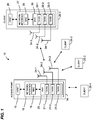
- Fig. 1 is a block diagram of an example WLAN 10 including an AP 14, according to an embodiment.
- the AP 14 includes a host processor 15 coupled to a network interface 16.
- the network interface 16 includes a medium access control (MAC) processing unit 18 and a physical layer (PHY) processing unit 20.
- the PHY processing unit 20 includes a plurality of transceivers 21, and the transceivers 21 are coupled to a plurality of antennas 24. Although three transceivers 21 and three antennas 24 are illustrated in Fig. 1 , the AP 14 can include different numbers (e.g., one, two, four, five, etc.) of transceivers 21 and antennas 24 in other embodiments.
- the WLAN 10 further includes a plurality of client stations 25. Although four client stations 25 are illustrated in Fig. 1 , the WLAN 10 can include different numbers (e.g., one, two, three, five, six, etc.) of client stations 25 in various scenarios and embodiments.
- Each of the client stations 25-1 through 25-4 is configured to operate at least according to a long range communication protocol. In some embodiments, one or more the client stations 25-1 through 25-4 is also configured to operate according to one or more of short range communication protocols.
- the client station 25-1 includes a host processor 26 coupled to a network interface 27.
- the network interface 27 includes a MAC processing unit 28 and a PHY processing unit 29.
- the PHY processing unit 29 includes a plurality of transceivers 30, and the transceivers 30 are coupled to a plurality of antennas 34.
- the client station 25-1 can include different numbers (e.g., one, two, four, five, etc.) of transceivers 30 and antennas 34 in other embodiments.
- one, some, or all of the client stations 25-2, 25-3, and 25-4 has/have a structure the same as or similar to the client station 25-1.
- the client stations 25 that are structured the same as or similar to the client station 25-1 have the same or a different number of transceivers and antennas.
- the client station 25-2 has only two transceivers and two antennas (not shown in Fig. 1 ), according to an embodiment.
- the PHY processing unit 20 of the AP 14 is configured to generate data units that conform to a long range communication protocol. More specifically, in some embodiments, the PHY processing unit 20 is configured to selectively generate both normal mode and low bandwidth mode data units that conform to the long range communication protocol.
- the PHY processing unit 20 is further configured to support both SU and MU operation that is similar to the SU and MU operation defined under the IEEE 802.11ac standard, in an embodiment.
- the PHY processing unit 20 is configured to selectively generate both SU data units intended for a single user (e.g., only client station 25-1), and MU data units intended for multiple users (e.g., two or more of client stations 25-1 through 25-4).
- MU transmissions use a "Group ID" to indicate which client stations are associated with a particular MU data unit sent by the AP 14, with Group IDs being assigned during group formation.
- the PHY processing unit 20 is configured to generate SU data units when in either normal mode or low bandwidth mode, but can only generate MU data units when in normal mode. In other embodiments, the PHY processing unit 20 is configured to generate SU data units and MU data units both when in normal mode and when in low bandwidth mode. Further, in an embodiment, the PHY processing unit 20 is configured to generate both SU-BF data units and SU-OL data units. In some embodiments, the PHY processing unit 20 is configured to generate SU-OL data units when in either normal mode or low bandwidth mode, but can only generate SU-BF data units when in normal mode. In other embodiments, the PHY processing unit 20 is configured to generate SU-OL and SU-BF data units both when in normal mode and when in low bandwidth mode.
- the transceiver(s) 21 of the AP 14 is/are configured to transmit the generated data units via the antenna(s) 24.
- the transceiver(s) 21 is/are also configured to receive data units via the antenna(s) 24, and the PHY processing unit 20 of the AP 14 is further configured to process received data units conforming to the long range communication protocol.
- the PHY processing unit 29 of the client station 25-1 is also configured to generate data units, and/or process received data units, conforming to the long range communication protocol. In some embodiments, however, the PHY processing unit 29 is not configured to generate MU data units, and/or is not configured to generate SU-BF data units.
- the transceiver(s) 30 is/are configured to transmit the generated data units via the antenna(s) 34, and/or receive data units via the antenna(s) 34.
- a transmitting device such as the AP 14 may send a "sounding" packet to a receiving device such as the client station 25-1, and the receiving device may process the sounding packet in order to derive channel information. Coefficients for the steering matrix may then be calculated at the receiving device based on that channel information, and sent back to the transmitting device.
- Figs. 2 and 3 shows prior art sounding techniques defined by the IEEE 802.11ac standard, which in some embodiments are also utilized by the WLAN 10 of Fig. 1 to support beamforming under the long range communication protocol.
- the "Beamformer" of Figs. 2 and 3 is the AP 14 of Fig. 1
- the "Beamformee” of Fig. 2 is the client station 25-1 of Fig. 1
- "Beamformees #1-#3" of Fig. 3 are the client stations 25-1 through 25-3, respectively, of Fig. 1 .
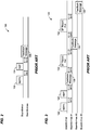
- Fig. 2 shows a prior art sounding technique 100 for SU beamforming.
- the beamformer sends a "null data packet announcement" (NDPA) packet 102 to a beamformee (i.e., to an intended recipient of a beamformed transmission).
- NDPA "null data packet announcement”
- the beamformer sends a "null data packet” (NDP) 104, which serves as a sounding packet, to the beamformee.
- NDP "null data packet”
- the beamformee processes the NDP 104 to calculate beamforming coefficients, and sends the coefficients back to the beamformer within feedback message 106.
- the beamformer then computes a steering vector to be used for beamformed transmissions to the beamformee.
- Fig. 3 shows a prior art sounding technique 120 for MU beamforming.
- the beamformer sends an NDPA packet 122 to all beamformees (#1-#3, in the example scenario of Fig. 3 ).
- the NDPA packet 122 includes a station (STA) information field, and is followed within a SIFS by an NDP packet 124.
- STA station
- NDP packet 124 The beamformee whose association identifier (AID) is included in the STA field of the NDPA packet 122 (i.e., "Beamformee #1" in the example scenario of Fig. 3 ) calculates beamforming coefficients based on the received NDP 124, and responds within a SIFS with a feedback message 126 that includes the calculated coefficients.
- AID association identifier
- the beamformer then polls subsequent stations (i.e., "Beamformee #2” then “Beamformee #3,” in the example scenario of Fig. 3 ) with poll signals 130 and 132, and the beamformees respond with feedback messages 134 and 136, respectively, that include the calculated beamforming coefficients.
- the beamformer uses the fed-back beamforming coefficients from all of the beamformees to compute a steering vector that is optimized to improve the reception of the MU data unit by all beamformees.
- the WLAN 10 of Fig. 1 uses another suitable technique, other than the example sounding techniques 100 and 120 of Figs. 2 and 3 , to obtain feedback information to be used for beamforming.
- Figs. 4-8 show example preamble formats used for different types of SU and MU data units, in either normal mode or low bandwidth mode, according to an embodiment.
- the PHY processing unit 20 of AP 14, and/or the PHY processing unit 29 of client station 25-1 is/are configured to generate data units with preambles that conform to the example formats of Figs. 4-8 .
- each of the preamble formats of Figs. 4-8 is described with reference to an embodiment and scenario in which the AP 14 transmits a data unit that uses the respective preamble format to the client station 25-1 (for an SU data unit), or to two or more of the client stations 25-1 through 25-4 (for an MU data unit).
- a sounding technique such as the example technique 100 or 120 of Fig. 2 or 3 is used to beamform SU-BF and/or MU data units that use the preamble formats of Figs. 4-8 .
- a sounding technique such as the example technique 100 or 120 of Fig. 2 or 3 is used to beamform SU-BF and/or MU data units that use the preamble formats of Figs. 4-8 .
- particular numbers of OFDM symbols are shown for the various fields in the preambles of Figs. 4-8 , other embodiments include different numbers of OFDM symbols in some or all of the fields.
- all "normal mode" preamble formats of Figs. 4-8 correspond to data units transmitted over a 2 MHz or greater bandwidth
- all "low bandwidth mode" preamble formats in Figs. 4-8 correspond to data units transmitted over a 1 MHz bandwidth.
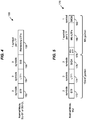
- the AP 14 uses the example preamble format 150 to generate a normal mode data unit, both for SU-BF data units and for non-beamformed, SU-OL data units, in an embodiment.
- the AP 14 uses the example preamble format 150 to generate normal mode, SU-OL data units, but not SU-BF data units.
- the preamble format 150 includes a short training field (STF) 152, a first long training field (LTF1) 154 after the STF 152, a signal (SIG) field 156 after the LTF1 154, and any remaining LTFs 158 after the SIG field 156.
- STF short training field
- LTF1 first long training field
- SIG signal
- SU data units using the preamble format 150 also include a data portion (not shown) immediately following the remaining LTFs 158.
- the client station 25-1 detects a data unit utilizing the preamble format 150 during reception of the STF 152.
- the client station 25-1 sets an AGC level based on the STF 152, uses the LTF1 154 and any remaining LTF(s) 158 for channel estimation (e.g., one LTF per spatial stream, such that LTFs 158 are omitted for the case of one spatial stream), and uses information bits in the SIG field 156 to determine certain PHY parameters associated with the data unit that utilizes the preamble format 150 (e.g., a modulation and coding scheme used in a data portion of the data unit, a length or duration of the data portion, etc.).
- channel estimation e.g., one LTF per spatial stream, such that LTFs 158 are omitted for the case of one spatial stream
- information bits in the SIG field 156 uses information bits in the SIG field 156 to determine certain PHY parameters associated with the data unit that utilizes the preamble format 150 (e.g., a modulation and coding scheme used in a data portion of the data unit, a length or duration of the data portion, etc.).
- the entire preamble 150 is beamformed, in addition to any data portion following the preamble 150. That is, a beamforming steering matrix is applied to the entire data unit, starting with the beginning of the STF 152.
- a beamforming steering matrix is applied to the entire data unit, starting with the beginning of the STF 152.
- the client station 25-1 would likely estimate channel parameters that only poorly reflect the channel corresponding to the beamformed portion of the data unit.
- applying beamforming to the entire data unit can lead to a "hidden node" problem.
- devices within range of the AP 14 that happen to be at a location that is largely orthogonal to the direction of the beamformed transmission e.g., any or all of client stations 25-2 through 25-4 may fail to decode information in the SIG field 156 that is indicative of the length or duration of the SU-BF data unit sent from the AP 14 to the client station 25-1.
- one or more other client stations may attempt to communicate with AP 14 while AP 14 is still transmitting to client station 25-1.
- the AP 14 uses the example preamble format 170 of Fig. 5 to generate a normal mode, MU data unit, in an embodiment.
- the preamble format 170 includes an "omni" portion that is not beamformed, and an "MU portion” that is beamformed.
- the omni portion of the preamble format 170 includes an STF 172, an LTF1 174 after the STF 172, and a first SIG (SIGA) field 176 after the LTF1 174.
- the MU portion of the preamble format 170 includes a multi-user STF (MU-STF) 178, multi-user LTFs (MU-LTFs) 180 for channel estimation for all users, and a second SIG (SIGB) field 182 containing user-specific SIG field information.
- MU-STF multi-user STF
- MU-LTFs multi-user LTFs
- SIGB second SIG
- normal mode, MU data units that use the preamble format 170 also include a data portion (not shown), carrying data for all users, that immediately follows the SIGB field 182. Because the omni portion of the preamble 170 is not beamformed, each of the multiple users (e.g., any of client stations 25-1 through 25-4) can detect the data unit based on the STF 172, decode PHY information such as group identifier in the SIGA field 176, etc.
- the MU preamble format 170 is relatively long.
- preamble formats that do not include both omni and beamformed portions e.g., preamble format 150
- preamble formats that do include both omni and beamformed portions e.g., preamble format 170
- long preamble formats e.g., preamble format 170
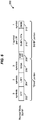
- a "long preamble" format similar to the preamble format 170 for normal mode, MU data units, is also used for normal mode, SU-BF data units.
- the long preamble format 200 includes an omni portion that is not beamformed, and an "SU-BF portion" that is beamformed.
- the omni portion of the preamble format 200 includes an STF 202, an LTF1 204 after the STF 202, and a first SIG (SIGA) field 206 after the LTF1 204.
- the SU-BF portion of the preamble format 200 includes a beamformed STF (SUBF-STF) 208, beamformed LTFs (SUBF-LTFs) 210 for channel estimation for each spatial stream, and a beamformed second SIG (SIGB) field 212.
- the SUBF-LTFs 210 include N LTFs, with a first of the N LTFs being repeated the same (or a similar) number of times as the LTF1 204 in the omni portion.
- the first LTF of the SUBF-LTFs of an SU-BF data unit is the same as the first LTF (LTF1) of an MU data unit.
- the first of the N LTFs in SUBF-LTFs 210 is only one OFDM symbol in length, and the field 212 is a duplicate of the first of the N LTFs, rather than a SIGB field as shown in Fig. 6 (so long as the SIGB field 212 is not needed to deliver information during SU-BF operation).
- the first LTF By repeating the first LTF, channel estimation reliability may be increased.
- normal mode, SU-BF data units that use the long preamble format 200 also include a beamformed data portion that immediately follows the SIGB (or LTF) field 212.
- the omni portion of the preamble 200 is not beamformed, other devices within range that are not intended recipients of the data unit using the long preamble format 200 can detect the data unit based on the STF 202, decode PHY information such as a length or duration of a data portion of the data unit in the SIGA field 206, etc. Therefore, communications using normal mode, SU-BF data units having the long preamble format 200 may suffer less from the hidden node problem than communications using normal mode, SU-BF data units having the short preamble format 150 of Fig. 4 , for example.
- a transmitting device such as the AP 14 of Fig. 1 is configured to selectively generate both normal mode, SU-BF data units having the short preamble format 150 and normal mode, SU-BF data units having the long preamble format 200.
- a transmitting device such as the AP 14 of Fig. 1 is configured to generate normal mode, SU-BF data units only using the long preamble format 200.
- the transmitting device is configured to generate normal mode, SU-OL data units using the short preamble format 150, and normal mode, SU-BF data units using the long preamble format 200.
- At least one device e.g., client station 25-1 is configured to generate normal mode, SU data units only using the short preamble format 150, and at least one other device (e.g., client station 25-2) in the same communication system (e.g., also in WLAN 10) is configured to generate normal mode, SU data units only using the long preamble format 200.
- Figs. 7 and 8 show example short and long preamble formats for low bandwidth mode data units, according to an embodiment.
- the AP 14 uses the example short preamble format 220 of Fig. 7 to generate low bandwidth mode data units, both for SU-BF and for SU-OL operation, in an embodiment.
- the AP 14 uses the short preamble format 220 to generate low bandwidth mode, SU-OL data units, but not low bandwidth mode, SU-BF data units.
- the short preamble format 220 includes an STF 222, an LTF1 224 after the STF 222, a SIG field 226 after the LTF1 224, and any remaining LTFs 228 after the SIG field 226.
- low bandwidth mode, SU data units using the short preamble format 220 also include a data portion (not shown) immediately following the remaining LTFs 228.
- the preamble is beamformed, in addition to any data portion following the preamble. That is, a beamforming steering matrix is applied to the entire data unit, starting with the beginning of the STF 222, in a manner similar to that described above with reference to the short preamble format 150 of Fig. 4 .
- a long preamble format is used for low bandwidth mode, SU-BF data units.
- Fig. 8 is a diagram of one such long preamble format 240. Similar to the long preamble format 200 of Fig. 6 , the long preamble format 240 includes an omni portion that is not beamformed, and an "SU-BF portion" that is beamformed. The omni portion of the long preamble format 240 includes an STF 242, an LTF1 244 after the STF 242, and a SIG field 246 after the LTF1 244.
- the SU-BF portion of the long preamble format 240 includes a beamformed STF (SUBF-STF) 248, and beamformed LTFs (SUBF-LTFs) 250 for channel estimation for each spatial stream.
- SUBF-STF beamformed STF
- SUBF-LTFs beamformed LTFs
- the SUBF-LTFs 250 include N LTFs, with each of the N LTFs having one, two, or four symbol repetitions. Because the omni portion of the long preamble format 240 is not beamformed, other devices within range that are not intended recipients of the data unit using the long preamble format 240 can detect the data unit based on the STF 242, decode PHY information such as a length of duration of a data portion in the SIG field 246, etc. Therefore, communications using low bandwidth mode, SU-BF data units that use the long preamble format 240 may suffer less from the hidden node problem than communications using low bandwidth mode, SU-BF data units that use the short preamble format 220 of Fig. 7 , for example.
- a transmitting device such as the AP 14 of Fig. 1 is configured to selectively generate both low bandwidth mode, SU-BF data units that use the short preamble format 220 and low bandwidth mode, SU-BF data units that use the long preamble format 240.
- a transmitting device such as the AP 14 of Fig. 1 is configured to generate low bandwidth mode, SU-BF data units only using the long preamble format 240.
- the transmitting device is configured to generate low bandwidth mode, SU-OL data units using the short preamble format 220, and low bandwidth mode, SU-BF data units using the long preamble format 240.
- At least one device e.g., client station 25-1 is configured to generate low bandwidth mode, SU-BF data units only using the short preamble format 220, and at least one other device (e.g., client station 25-2) is configured to generate low bandwidth mode, SU-BF data units only using the long preamble format 240.
- devices within a single communication system can generate data units according to some or all of the various long and short, SU and MU preamble formats shown in Figs. 4-8
- devices receiving a data unit are configured to detect the preamble format utilized by the data unit.
- a preamble “format” can refer to the arrangement and/or types of fields within the preamble (e.g., the arrangement of any STF(s), LTF(s), SIG field(s), etc.), and/or to the arrangement and types of subfields within one or more particular preamble fields (e.g., which PHY parameters are specified within a SIG field of the preamble, the location of the subfields corresponding to those PHY parameters, etc.).
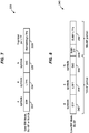
- Fig. 9 illustrates an example technique for auto-detecting whether a data unit includes a short preamble format (e.g., similar to short preamble format 150 of Fig. 4 ) or a long preamble format (e.g., similar to long preamble format 170 of Fig. 5 or long preamble format 200 of Fig. 6 ), according to an embodiment.
- Fig. 9 can also be used to auto-detect whether the data unit is a low bandwidth mode data unit or a normal mode data unit, which in some embodiments can also determine the preamble format (e.g., in embodiments where low bandwidth mode data units utilize only a short preamble format, and/or in embodiments where low bandwidth mode data units have a different number of OFDM symbols in certain fields as compared to normal mode data units, etc.).
- various preamble portions are shown starting from the beginning of the first LTF of the preamble. The beginning of the first LTF (after the STF) marks the first point at which the receiving device can achieve time alignment with respect the received data unit, in an embodiment.
- a first preamble portion 300 corresponds to a short preamble of a normal mode, SU (i.e., SU-OL or SU-BF) data unit, and includes a double guard interval (DGI) 302, a first OFDM symbol 304 of an LTF, a second OFDM symbol 306 of the LTF, a guard interval (GI) 310, a first OFDM symbol 312 of a SIG field, another GI 314, and a second OFDM symbol 316 of the SIG field, in an embodiment.
- DGI double guard interval
- GI guard interval
- a second preamble portion 320 corresponds to a long preamble of a normal mode, MU or SU-BF data unit, and includes a DGI 322, a first OFDM symbol 324 of an LTF, a second OFDM symbol 326 of the LTF, a GI 330, a first OFDM symbol 332 of a SIG field, another GI 334, and a second OFDM symbol 336 of the SIG field, in an embodiment.
- a third preamble portion 340 corresponds to a either a short or long preamble of a normal mode, SU (i.e., SU-BF or SU-OL) data unit, and includes a DGI 342, a first OFDM symbol 344 of an LTF, a second OFDM symbol 346 of the LTF, a GI 350, a third OFDM symbol 352 of the LTF, another GI 354, and a fourth OFDM symbol 356 of the LTF, in an embodiment.
- the preamble portion 300 corresponds to the LTF1 154 and SIG field 156 of the short preamble format 150 of Fig.
- the preamble portion 320 corresponds either to the LTF1 174 and SIGA field 176 of the long preamble format 170 of Fig. 5 (for an MU data unit), or to the LTF1 204 and SIGA field 206 of the long preamble format 200 of Fig. 6 (for an SU-BF data unit), and the preamble portion 340 corresponds either to the LTF1 224 and SIG field 226 of the short preamble format 220 of Fig. 7 , or to the LTF1 244 and SIG field 246 of the long preamble format 240 of Fig. 8 .
- a data unit is a normal mode data unit or a low bandwidth mode data unit is indicated by the modulation type used for the third OFDM symbol from the start of the LTF.
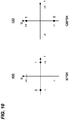
- the OFDM symbol 312 (first SIG field symbol) of preamble portion 300, and the OFDM symbol 332 (first SIGA field symbol) of preamble portion 320 are modulated using quaternary binary phase shift key (QBPSK) modulation to indicate a normal mode data unit rather than a low bandwidth mode data unit.
- QBPSK quaternary binary phase shift key
- the OFDM symbol 352 (third LTF symbol) of preamble portion 340 is modulated using binary phase shift key (BPSK) modulation to indicate a low bandwidth mode data unit rather than a normal mode data unit.
- BPSK binary phase shift key
- a receiver detects whether a received data unit is a normal mode data unit or low bandwidth mode data unit by detecting the rotation of the symbol constellation in the third OFDM symbol after the end of the STF.
- BPSK instead indicates normal mode and QBPSK instead indicates low bandwidth mode
- the modulation of a different OFDM symbol is used to indicate normal mode or low bandwidth mode
- a different symbol constellation e.g., QPSK, 16-QAM, etc.
- a normal mode data unit utilizes a short preamble format (e.g., similar to short preamble format 150 of Fig. 4 ) or a long preamble format (e.g., similar to long preamble format 170 of Fig. 5 or long preamble format 200 of Fig. 6 ) is indicated by the modulation type used for the fourth OFDM symbol from the start of the LTF.
- the OFDM symbol 316 (second SIG field symbol) of preamble portion 300 is modulated using QBPSK modulation to indicate a short preamble format rather than a long preamble format.
- the OFDM symbol 336 (second SIGA symbol) of preamble portion 320 is modulated using BPSK modulation to indicate a long preamble format rather than a short preamble format.
- a receiver detects whether a received data unit utilizes a short or a long preamble format by detecting the rotation of the symbol constellation in the fourth OFDM symbol after the end of the STF.
- BPSK instead indicates a short preamble format and QBPSK instead indicates a long preamble format
- the modulation of a different OFDM symbol (other than the fourth OFDM symbol following the STF) is used to indicate whether a longer or shorter preamble format is used, and/or a different symbol constellation (e.g., QPSK, 16-QAM, etc.) is rotated to indicate whether a long or a short preamble format is used.
- a different symbol constellation e.g., QPSK, 16-QAM, etc.
- low bandwidth mode data units may use either a short preamble format (e.g., similar to preamble format 220 of Fig. 7 ) or a long preamble format (e.g., similar to preamble format 240 of Fig. 7 ), symbol constellation rotations of OFDM symbols are also used by a receiver to detect whether a low bandwidth mode data unit uses the short or the long preamble format.
- a short preamble format e.g., similar to preamble format 220 of Fig. 7
- a long preamble format e.g., similar to preamble format 240 of Fig. 7
- the receiver determines that the data unit uses a short preamble format, while QBPSK modulation instead indicates a long preamble format (or vice versa).
- determining whether a short or long preamble format is used by a low bandwidth mode data unit is equivalent to determining whether the data unit is an SU-OL data unit or an SU-BF data unit.
- Fig. 9 shows an example technique for auto-detecting whether a short or a long preamble format is used (in addition to auto-detecting whether the preamble belongs to a low bandwidth mode or a normal mode data unit), another mechanism is needed to allow a receiver to determine whether a data unit with a long preamble format is an SU-BF data unit or an MU data unit, in some embodiments.
- the auto-detections of Fig. 9 based on symbol constellation rotations do not sufficiently distinguish SU-BF data units from MU data units.
- a receiver may still need to determine whether a data unit is an SU-BF data unit or an MU data unit in order to determine the types of subfields, and/or the number of bits per subfield, in a SIG field of the long preamble.
- a SIG field in the omni portion of each preamble that conforms to the long preamble format indicates whether the data unit is an SU-BF data unit or an MU data unit by way of a Group ID (GID) subfield in the SIG field.
- GID Group ID
- a SIG field with a GID value in a particular subset of one or more GID values indicates that the data unit is an SU-BF data unit, while all other GID values (e.g., 1 through 62) indicate that the data unit is an MU data unit, in an embodiment.
- the GID subfield retains its "normal" function of indicating which stations are associated with the MU data unit, in an embodiment.
- Table 1 shows an example arrangement/format of subfields and bits in a first SIG field of the preamble (e.g., SIG field 156 of short preamble format 150 in Fig. 4 , SIGA field 176 of long preamble format 170 in Fig. 5 , or SIGA field 206 of long preamble format 200 in Fig.
- SIG field 156 of short preamble format 150 in Fig. 4 SIGA field 176 of long preamble format 170 in Fig. 5
- SIGA field 206 of long preamble format 200 in Fig.
- the coding subfield for SU-BF data units with the long preamble format use one bit as the LDPC additional bit and one bit as the LDPC/BCC indicator of the single user.
- the Nsts portion that would normally (for an MU data unit) correspond to a first of multiple users has a non-zero value, while the remaining Nsts values are all zero.
- some of the "reserved" bits for the SU-BF, longer preamble format case are instead used for a PAID subfield.
- the MCS for an SU-BF data unit using the long preamble format is signaled in a later SIG field, such as the SIGB field 212 of the long preamble format 200 in Fig. 6 .
- the subfields and bits of the first SIG field e.g., SIG field 156 of short preamble format 150 in Fig. 4 , SIGA field 176 of long preamble format 170 in Fig. 5 , or SIGA field 206 of long preamble format 200 in Fig.
- Table 2 Subfield SU with short preamble format e.g., bits in SIG field 156)
- MU with long preamble format e.g., bits in SIGA field 176)
- SU-BF with long preamble format e.g., bits in SIGA field 206)
- Length/Duration 9 9 9 MCS 4 0 4 BW 2 2 Aggregation 1 0 1 (or 0 if always aggregated)
- STBC 1 1 1 Coding 2 5 2 SGI 1 1 1 1 GID 0 6 6 e.g., set to 0 or 63
- Nsts 2 8 2 PAID 9 0 N e.g., 0 to 9)
- Reserved 7 6 Depends on number of bits in PAID and aggregation fields
- the various SIG subfields shown in Table 2 are the same or similar to the like-named
- the coding and Nsts subfields are shortened for the SU-BF, long preamble format in order to avoid wasting the excess bits.
- the SU-BF, long preamble format defines an MCS subfield for the first SIG field.
- any later SIG fields e.g., SIGB field 212 in Fig. 6
- the SU-BF data units using the long preamble format therefore do not include a second SIG field (e.g., SIGB field 212 is replaced with an LTF, or omitted, etc., in various embodiments).
- a SIG field in the omni portion of each preamble conforming to the long preamble format includes an "MU/SU" bit that indicates whether the data is an SU-BF data unit or an MU data unit, rather than indicating SU or MU operation with a GID subfield.
- the GID field is omitted from the SIG field of SU-BF data units that use the long preamble format (e.g., SIGA field 206 of long preamble format 200 in Fig.
- the SIG field format for SU-BF data units having the long preamble format is very similar to that in Table 2 (e.g., an MCS subfield is included).
- an MU/SU subfield is added to distinguish MU and SU-BF operation in data units having the long preamble format, and the GID subfield is omitted (in the SU-BF case) because it is no longer used to distinguish MU and SU-BF operation, and serves no other purpose for SU-BF operation.
- any later SIG fields in an SU-BF data unit using the long preamble format e.g., the SIGB field 212 in Fig. 6
- the SU-BF data units using the long preamble format therefore do not include a second SIG field (e.g., SIGB field 212 is replaced with an LTF, or omitted, etc., in various embodiments).
- SU-BF operation when using a long preamble format, is merely a subset of MU operation, for the special case in which only one user has data to be transmitted (i.e., where a non-zero number of space-time streams correspond to the single user, while no space-time streams correspond to any other users).
- no "special" GID values are reserved to signify SU-BF operation. Rather, the single user is mapped to a GID just as any other users would be mapped to a GID in standard MU operation.
- Table 4 shows an example arrangement/format of subfields and bits in a first SIG field of a preamble (e.g., SIG field 156 of short preamble format 150 in Fig.
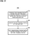
- Fig. 11 is a flow diagram of an example method 500 for generating a data unit, according to one embodiment and scenario.
- the method 500 is implemented by the network interface 16 of AP 14 of Fig. 1 , in one embodiment and scenario.
- a preamble of a first data unit is generated according to a first format (e.g., a long preamble format). More specifically, a first preamble portion of the first data unit is generated at block 510, and a second preamble portion of the first data unit is generated at block 520.
- the first preamble portion generated at block 510 includes information indicating to a receiving device that the first data unit is an SU data unit.
- the second preamble portion generated at block 520 follows the first preamble portion generated at block 510.
- generating the first preamble portion at block 510 includes generating a SIG field that indicates PHY parameters associated with the first data unit to a receiving device.
- the generated SIG field includes the information (referenced above) that indicates to the receiving device that the first data unit is an SU data unit. For example, a bit in an MU/SU subfield of the SIG field indicates that the first data unit is an SU data unit, in one embodiment and scenario. In another example embodiment and scenario, a certain value or range of values in a Group ID (GID) subfield of the SIG field indicates that the first data unit is an SU data unit.
- the SIG field also includes information indicating other PHY parameters of the first data unit, such as a modulation and coding scheme of a data portion of the first data unit.
- generating the first preamble portion at block 510 includes generating an STF, an LTF and a first SIG field similar to STF 202, LTF1 204, and SIGA field 206 of Fig. 6 , respectively, and/or generating the second preamble portion at block 520 includes generating an STF, one or more additional LTFs, and a second SIG field similar to SUBF-STF 208, SUBF-LTFs 210, and SIGB field 212, respectively.
- a beamforming steering matrix is applied to the second preamble portion of the first data unit.
- the beamforming steering matrix is not applied, however, to the first preamble portion of the first data unit.
- the first preamble portion serves as an "omni" portion, which may be more easily detected by devices other than the intended recipient of the first data unit.
- the method 500 includes other blocks not seen in Fig. 11 .
- the method 500 includes a first additional block in which a data portion of the first data unit is generated, where the data portion follows the second preamble portion generated at block 520, and a second additional block in which the beamforming steering matrix is also applied to the data portion of the first data unit.
- the method 500 includes additional blocks in which a preamble of a second data unit is generated according to a second format (e.g., short preamble format) different than the first format of the first data unit preamble.
- Generating the preamble of the second data unit according to the second format includes generating a first preamble portion of the second data unit and a second preamble portion of the data unit, in an embodiment.
- the first preamble portion of the second data unit includes information indicating to a receiving device that the second data unit is an MU data unit, and the second preamble portion of the second data unit follows the first preamble portion of the second data unit.
- one or more beamforming steering matrices are applied to the second preamble portion of the second data unit, but not to the first preamble portion of the second data unit.
- the first preamble portion of the first data unit includes a SIG field containing information indicating to a receiving device that the first data unit is an SU data unit
- the first preamble portion of the second data unit includes a SIG field containing information indicating to a receiving device that the second data unit is an MU data unit (e.g., an MU/SU bit, or a GID subfield, as described above).
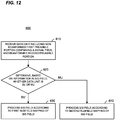
- Fig. 12 is a flow diagram of an example method 600 for receiving and processing a data unit, according to an embodiment.
- the method 600 is implemented by the network interface 27 of client station 25-1, in one embodiment and scenario.
- the method 600 is used when receiving a data unit generated using the method 500 of Fig. 11 .
- the method 600 is used when receiving a data unit having a preamble format similar to any of the long preamble format 170 of Fig. 5 , the long preamble format 200 of Fig. 6 , or the long preamble format 240 of Fig. 8 .
- a data unit is received.
- the data unit includes a preamble having a first preamble portion that is not beamformed, and a second preamble portion that is beamformed.
- the first preamble portion includes a SIG field indicating a plurality of PHY parameters associated with the received data unit.
- determining whether the data unit is an SU data unit or an MU data unit is equivalent to determining whether the data unit is an SU-BF data unit or an MU data unit.
- the SIG field of the data unit is processed according to a first subfield mapping of the SIG field.
- the first subfield mapping is the mapping shown in the "SU-BF with long preamble format" column of Table 1, Table 2, or Table 3, above.
- the processing at block 630 includes determining a modulation and coding scheme (MCS) of the received data unit based on one or more information bits in an MCS subfield of the SIG field.
- MCS modulation and coding scheme
- the processing at block 630 includes determining a partial association identifier (PAID) associated with the received data unit based on one or more information bits in a PAID subfield of the SIG field.
- PAID partial association identifier
- the SIG field of the data unit is processed according to a second subfield mapping of the SIG field, different than the first subfield mapping.
- the second subfield mapping is the mapping shown in the "MU with long preamble format" column of Table 1, Table 2, or Table 3, above.
- the processing at block 640 includes determining a group identifier (GID) of the received data unit based on one or more information bits in a GID subfield of the SIG field.
- GID group identifier
- the method 600 includes other blocks not seen in Fig. 11 .
- the method 600 includes an additional block in which a data portion of the data unit received at block 610 is processed, based on one or more PHY parameters indicated in one or more subfields of the SIG field.
- the method 600 is repeated for each data unit of a plurality of received data units.
- Fig. 13 is a flow diagram of another example method 700 for receiving and processing a data unit, according to an embodiment.
- the method 700 is implemented by the network interface 27 of client station 25-1, in one embodiment and scenario.
- the method 700 is used when receiving a data unit having a preamble format similar to any of the short preamble format 150 of Fig. 4 , the long preamble format 170 of Fig. 5 , the long preamble format 200 of Fig. 6 , or the long preamble format 240 of Fig. 8 .
- a data unit is received.
- the data unit includes a preamble having a first preamble portion, and a second preamble portion following the first preamble portion.
- the first preamble portion includes a SIG field indicating a plurality of PHY parameters associated with the received data unit.
- a symbol constellation rotation of one or more OFDM symbols in the first preamble portion is detected.
- BPSK or QBPSK is utilized for a particular OFDM symbol (or set of symbols) in the first preamble portion, for example, the 0 degree or 90 degree rotation of the modulation is detected at block 720.
- the OFDM symbol(s) for which the constellation rotation is detected is/are located in a SIG field of the first preamble portion.
- the preamble of the data unit received at block 710 conforms to a first format (e.g., a short preamble format).
- a first format e.g., a short preamble format.
- the preamble conforms to the first format if BPSK is utilized, and that the preamble does not conform to the first format if QBPSK is utilized, or vice versa.
- the first format is a particular arrangement of fields within the preamble, such as the example preamble format 150 of Fig. 4 .
- the second preamble portion of the data unit received at block 710 is processed according to the first format.
- the first format is known to include at least one LTF at the beginning of the second preamble portion.
- the processing at block 740 includes utilizing an LTF, located at a beginning of the second preamble portion of the data unit received at block 710, to estimate a channel response.
- block 750 it is determined whether one or more information bits in the first preamble portion of the data unit received at block 710 indicate an SU data unit or an MU data unit. In an embodiment where SU-OL data units do not employ a long preamble format having an omni portion, determining whether the information bit(s) indicate an SU data unit or an MU data unit is equivalent to determining whether the information bit(s) indicate an SU-BF data unit or an MU data unit. In an embodiment, the information bit(s) used to make the determination at block 730 is/are included in a SIG field of the first preamble portion.
- the second preamble portion of the data unit received at block 710 is processed according to a second format different than the first format.
- the second format is known to be a preamble format used for SU, but not MU, data units (e.g., an SU-BF long preamble format).
- the second format corresponds to a particular arrangement of fields within the preamble, such as the arrangement within the example long preamble format 200 of Fig. 6 , for example.
- the processing at block 760 includes both utilizing an STF at a beginning of the second preamble portion to set an AGC level of a receiver device implementing the method 700, and utilizing one or more LTFs of the second preamble portion to estimate one or more channel responses corresponding to one or more respective spatial streams associated with a single user (i.e., the user corresponding to the device implementing the method 700).
- the second format is also known, by the receiving device, to include in the second preamble portion a duplicate of the first LTF of the second preamble portion.
- the SIGB field 212 is instead a duplicate of the first LTF of SUBF-LTFs 210.
- the processing at block 760 also includes utilizing the additional, duplicate LTF to help estimate the channel response of the spatial stream corresponding to the first LTF of the second preamble portion.
- the processing at block 760 is also based on a knowledge of the subfield types and locations in a SIG field of the first preamble portion, as specified by the second format.
- the second format specifies an arrangement of the SIG field of the first preamble portion as shown in the "SU-BF with long preamble format" column of Table 1, Table 2, or Table 3, above.
- the second preamble portion of the data unit received at block 710 is processed according to a third format different than both the first format and the second format.
- the third format is known to be a preamble format used for MU, but not SU, data units (e.g., an MU long preamble format).
- the third format corresponds to a particular arrangement of fields within the preamble, such as the arrangement of the example long preamble format 170 of Fig. 5 , for example.
- the processing at block 770 includes both utilizing an STF at a beginning of the second preamble portion to set an AGC level of a receiver device implementing the method 700, and utilizing one or more LTFs of the second preamble portion to estimate one or more channel responses associated with a single user (i.e., the user corresponding to the device implementing the method 700).
- the MU processing at block 770 is performed with knowledge that the LTFs in the second preamble portion include LTFs associated with multiple users (i.e., only a subset of the LTFs in the second preamble portion should be used for channel estimation by the receiving device).
- the third format also includes a SIG field in the second preamble portion, which follows the LTFs of the second preamble portion and contains information bits that indicate one or more PHY parameters associated with the received data unit and the multiple users.
- the processing at block 770 further includes decoding information bits in the SIG field of the second preamble portion.
- the processing at block 770 is also based on a knowledge of the subfield types and locations in a SIG field of the first preamble portion, as specified by the third format.
- the third format specifies an arrangement of the SIG field of the first preamble portion as shown in the "MU with long preamble format" column of Table 1, Table 2, or Table 3, above.
- the method 700 includes other blocks not seen in Fig. 13 .
- the method 700 includes a first additional block in which a symbol constellation rotation of one or more additional OFDM symbols in the first preamble portion is detected, and a second additional block in which it is determined, based on the detected symbol constellation rotation of the additional OFDM symbol(s), whether the data unit corresponds to a first channel bandwidth (e.g., whether the data unit is a low bandwidth mode data unit).
- the symbol constellation rotation of a first OFDM symbol of a SIG field of the first preamble portion is detected at block 720, and the symbol constellation rotation of a second OFDM symbol of the SIG field of the first preamble portion is detected in an additional block, in an embodiment (e.g., as shown in the example preamble portions 300 and 320 of Fig. 9 ).
- the method 700 is repeated for each data unit of a plurality of received data units.
- the various blocks, operations, and techniques described above may be implemented utilizing hardware, a processor executing firmware instructions, a processor executing software instructions, or any combination thereof.
- the software or firmware instructions may be stored in any computer readable memory such as on a magnetic disk, an optical disk, or other storage medium, in a RAM or ROM or flash memory, processor, hard disk drive, optical disk drive, tape drive, etc.
- the software or firmware instructions may be delivered to a user or a system via any known or desired delivery method including, for example, on a computer readable disk or other transportable computer storage mechanism or via communication media.
- Communication media typically embodies computer readable instructions, data structures, program modules or other data in a modulated data signal such as a carrier wave or other transport mechanism.
- modulated data signal means a signal that has one or more of its characteristics set or changed in such a manner as to encode information in the signal.
- communication media includes wired media such as a wired network or direct-wired connection, and wireless media such as acoustic, radio frequency, infrared and other wireless media.
- the software or firmware instructions may be delivered to a user or a system via a communication channel such as a telephone line, a DSL line, a cable television line, a fiber optics line, a wireless communication channel, the Internet, etc. (which are viewed as being the same as or interchangeable with providing such software via a transportable storage medium).
- the software or firmware instructions may include machine readable instructions that, when executed by the processor, cause the processor to perform various acts.
- the hardware may comprise one or more of discrete components, an integrated circuit, an application-specific integrated circuit (ASIC), etc.
- ASIC application-specific integrated circuit
Landscapes
- Engineering & Computer Science (AREA)
- Signal Processing (AREA)
- Computer Networks & Wireless Communication (AREA)
- Multimedia (AREA)
- Mobile Radio Communication Systems (AREA)
- Radio Transmission System (AREA)
Description
- This disclosure claims the benefit of the following U.S. Provisional Patent Applications:
-
U.S. Provisional Patent Application No. 61/586,565 -
U.S. Provisional Patent Application No. 61/587,386 -
U.S. Provisional Patent Application No. 61/591,718 -
U.S. Provisional Patent Application No. 61/610,725 -
U.S. Provisional Patent Application No. 61/674,724 - The present application is related to U.S. Patent Application
US201313741077 - The present disclosure relates generally to communication networks and, more particularly, to long-range wireless local area networks.
- The background description provided herein is for the purpose of generally presenting the context of the disclosure. Work of the presently named inventors, to the extent it is described in this background section, as well as aspects of the description that may not otherwise qualify as prior art at the time of filing, are neither expressly nor impliedly admitted as prior art against the present disclosure.
- When operating in an infrastructure mode, wireless local area networks (WLANs) typically include an access point (AP) and one or more client stations. WLANs have evolved rapidly over the past decade. Development of WLAN standards such as the Institute for Electrical and Electronics Engineers (IEEE) 802.11a, 802.11b, 802.11g, and 802.11n Standards has improved single-user peak data throughput. For example, the IEEE 802.11b Standard specifies a single-user peak throughput of 11 megabits per second (Mbps), the IEEE 802.11a and 802.11g Standards specify a single-user peak throughput of 54 Mbps, the IEEE 802.11n Standard specifies a single-user peak throughput of 600 Mbps, and the IEEE 802.11ac Standard specifies a single-user peak throughput in the gigabits per second (Gbps) range.
- Work has begun a new standard, IEEE 802.11ah, which will specify wireless network operation in sub-1GHz frequencies. Low frequency communication channels are generally characterized by better propagation qualities and extended propagation ranges compared to transmission at higher frequencies. In the past, sub-1 GHz ranges have not been utilized for wireless communication networks because such frequencies were reserved for other applications (e.g., licensed TV frequency bands, radio frequency band, etc.). There are few frequency bands in the sub-1 GHz range that remain unlicensed, with different specific unlicensed frequencies in different geographical regions. The IEEE 802.11ah Standard will specify wireless operation in available unlicensed sub-1GHz frequency bands.
-
US 2010/0260159 A1 relates to wireless local area networks that utilize orthogonal frequency division multiplexing. In a technique for generating a data unit for transmissions via a communication channel, wherein the data unit conforms to a first communication protocol, a preamble of the data unit is generated. The preamble includes a first field having information that indicates a duration of the data unit, the first field being formatted such that the first field is decodable by a receiver device that conforms to a second communication protocol but does not conform to the first communication protocol to determine the duration of the data unit based on the first field. Additionally, the preamble is formatted such that a portion of the preamble is decodable by a receiver device that conforms to a third communication protocol but does not conform to the first communication protocol. Also, the preamble is formatted such that a receiver device that conforms to the first communication protocol can determine that the data unit conforms to the first communication protocol. A data portion of the data unit that conforms to the first communications protocol and does not conform to either (i) the second communication protocol or (ii) the third communication protocol is generated. - It is the object of the present invention to improve efficiency of prior art techniques. This object is solved by the subject matter of the independent claims. Preferred embodiments are defined by the dependent claims.
-
-
Fig. 1 is a block diagram of an example wireless local area network (WLAN), according to an embodiment. -
Fig. 2 is a diagram of a prior art sounding technique for single-user beamforming. -
Fig. 3 is a diagram of a prior art sounding technique for multi-user beamforming. -
Fig. 4 is a diagram of an example preamble format used for normal mode, single-user (SU) data units, according to an embodiment. -
Fig. 5 is a diagram of an example preamble format used for normal mode, multi-user (MU) data units, according to an embodiment. -
Fig. 6 is a diagram of an example preamble format used for normal mode, SU beamformed (SU-BF) data units, according to an embodiment. -
Fig. 7 is a diagram of an example preamble format used for low bandwidth mode, SU data units, according to an embodiment. -
Fig. 8 is a diagram of an example preamble format used for low bandwidth mode, SU-BF data units, according to an embodiment. -
Fig. 9 is a diagram of corresponding preamble portions of an example normal mode, SU data unit, an example normal mode, MU or SU-BF data unit, and an example low bandwidth mode, SU data unit, according to an embodiment. -
Fig. 10 is a diagram illustrating example modulation techniques used to modulate symbols within a data unit preamble, according to an embodiment. -
Fig. 11 is a flow diagram of an example method for generating a data unit, according to an embodiment. -
Fig. 12 is a flow diagram of an example method for receiving and processing a data unit, according to an embodiment. -
Fig. 13 is a flow diagram of another example method for receiving and processing a data unit, according to an embodiment. - In embodiments described below, a wireless network device such as an access point (AP) of a wireless local area network (WLAN) transmits data streams to one or more client stations. The AP is configured to operate with client stations according to a communication protocol. In an embodiment, the communication protocol defines operation in a sub-1 GHz frequency range, and is typically used for applications requiring long range wireless communication with relatively low data rates (e.g., IEEE 802.11ah). Example formats of physical layer (PHY) data units of such a protocol, according to various embodiments, are described in
U.S. Patent Application No. 13/359,336 , "Physical Layer Frame Format For Long Range WLAN." - In some embodiments, the communication protocol specifies both a first PHY mode (referred to herein as a "normal mode") for larger data rates, and a second PHY mode (referred to herein as a "low rate mode") for lower data rates. A lower data rate mode may be used to further extend the communication range, for example, and generally improves receiver sensitivity (or sensitivity gain). In some embodiments, the low rate mode utilizes not only a lower data rate, but also a lower channel bandwidth, as compared to the normal mode. This reduced-bandwidth PHY mode is referred to herein as "low bandwidth mode." In one example embodiment, low bandwidth mode data units are generated using a 32-point inverse discrete Fourier transform (IDFT) for transmission over a 1 MHz bandwidth, while normal mode data units are generated using a 64-point or larger IDFT for transmission over a 2 MHz or greater bandwidth, where both low bandwidth mode and normal mode data units are generated using the same clock rate. Example formats of low rate mode data units (including low bandwidth mode data units), and the generation of such data units, according to various embodiments, are described in
U.S. Patent Application No. 13/366,064 , "Control Mode PHY for WLAN," andU.S. Patent Application No. 13/494,505 , "Low Bandwidth PHY for WLAN." Low bandwidth mode communications are generally more robust than normal mode communications, having a sensitivity gain that supports extended range communications. - In some embodiments, a transmitting device such as an AP or client station is capable of beamforming transmitted data units. As used herein, the terms "beamforming" and "beamformed" generally refer to transmit-side beamforming (i.e., applying a beamforming steering matrix at the transmitting device) rather than receive-side beamforming. Moreover, in an embodiment, the transmitting device supports both single-user (SU) operation and multi-user, multiple-input multiple-output (MU-MIMO) operation, similar to the SU and MU-MIMO operation as defined under IEEE 802.11ac. For convenience, MU-MIMO operation is referred to herein simply as MU operation. While MU operation inherently utilizes beamforming, SU data units generally may be either beamformed (SU-BF data units) or non-beamformed (i.e., "open loop," or SU-OL data units). In various embodiments, the transmitting device is capable of generating both SU-BF data units and MU data units when in normal mode.
- For MU data units, the transmitting device utilizes a preamble format that includes a first, non-beamformed portion intended for all of the multiple users (generally referred to herein as an "omni" portion, although the portion may be transmitted via a directional antenna or antenna array), and a second portion with various fields (e.g., long training fields) that are beamformed using a different beamforming steering matrix for each user. In some embodiments and/or scenarios, the transmitting device utilizes a different, shorter preamble format to transmit SU-BF data units, where the omni portion of the preamble is omitted and an entirety of the preamble is beamformed. By applying beamforming to the entire SU-BF data unit, a receiving device can properly set an automatic gain control (AGC) level based on the first received field of the preamble, for example. Beamforming the entire SU-BF data unit, however, can cause other devices (e.g., devices located in a direction orthogonal to the beamformed transmission) to fail to detect and/or decode any portion of the SU-BF data unit. This can result in the classic "hidden node" problem, in which multiple devices (e.g., client stations) attempt to communicate with another device (e.g., an AP) at the same time, causing interference. Thus, in one embodiment, the transmitting device instead generates SU-BF data units utilizing a longer preamble format with both non-beamformed (omni) and beamformed portions, similar to the MU data unit preamble format. The omni portion allows devices other than the intended recipient of the data unit to detect the SU-BF data unit, and/or to decode information in the SU-BF data unit preamble that indicates a duration of a data portion of the SU-BF data unit, for example.
- In some embodiments, one or more orthogonal frequency division multiplexing (OFDM) symbols of the preamble of each data unit is/are modulated using a symbol constellation rotation that indicates whether the longer preamble format (with both omni and beamformed portions) or the shorter preamble format is used for the data unit. Moreover, in some embodiments and scenarios where the longer preamble format is used, the omni portion of the preamble includes a field with information that indicates to a receiving device whether the data unit is an MU data unit or an SU-BF data unit.
-
Fig. 1 is a block diagram of anexample WLAN 10 including anAP 14, according to an embodiment. TheAP 14 includes ahost processor 15 coupled to anetwork interface 16. Thenetwork interface 16 includes a medium access control (MAC)processing unit 18 and a physical layer (PHY)processing unit 20. ThePHY processing unit 20 includes a plurality of transceivers 21, and the transceivers 21 are coupled to a plurality of antennas 24. Although three transceivers 21 and three antennas 24 are illustrated inFig. 1 , theAP 14 can include different numbers (e.g., one, two, four, five, etc.) of transceivers 21 and antennas 24 in other embodiments. - The
WLAN 10 further includes a plurality of client stations 25. Although four client stations 25 are illustrated inFig. 1 , theWLAN 10 can include different numbers (e.g., one, two, three, five, six, etc.) of client stations 25 in various scenarios and embodiments. Each of the client stations 25-1 through 25-4 is configured to operate at least according to a long range communication protocol. In some embodiments, one or more the client stations 25-1 through 25-4 is also configured to operate according to one or more of short range communication protocols. - The client station 25-1 includes a
host processor 26 coupled to anetwork interface 27. Thenetwork interface 27 includes aMAC processing unit 28 and aPHY processing unit 29. ThePHY processing unit 29 includes a plurality of transceivers 30, and the transceivers 30 are coupled to a plurality of antennas 34. Although three transceivers 30 and three antennas 34 are illustrated inFig. 1 , the client station 25-1 can include different numbers (e.g., one, two, four, five, etc.) of transceivers 30 and antennas 34 in other embodiments. - In some embodiments, one, some, or all of the client stations 25-2, 25-3, and 25-4 has/have a structure the same as or similar to the client station 25-1. In these embodiments, the client stations 25 that are structured the same as or similar to the client station 25-1 have the same or a different number of transceivers and antennas. For example, the client station 25-2 has only two transceivers and two antennas (not shown in
Fig. 1 ), according to an embodiment. - In an embodiment, the
PHY processing unit 20 of theAP 14 is configured to generate data units that conform to a long range communication protocol. More specifically, in some embodiments, thePHY processing unit 20 is configured to selectively generate both normal mode and low bandwidth mode data units that conform to the long range communication protocol. ThePHY processing unit 20 is further configured to support both SU and MU operation that is similar to the SU and MU operation defined under the IEEE 802.11ac standard, in an embodiment. Thus, in an embodiment, thePHY processing unit 20 is configured to selectively generate both SU data units intended for a single user (e.g., only client station 25-1), and MU data units intended for multiple users (e.g., two or more of client stations 25-1 through 25-4). In an embodiment, MU transmissions use a "Group ID" to indicate which client stations are associated with a particular MU data unit sent by theAP 14, with Group IDs being assigned during group formation. - In some embodiments, the
PHY processing unit 20 is configured to generate SU data units when in either normal mode or low bandwidth mode, but can only generate MU data units when in normal mode. In other embodiments, thePHY processing unit 20 is configured to generate SU data units and MU data units both when in normal mode and when in low bandwidth mode. Further, in an embodiment, thePHY processing unit 20 is configured to generate both SU-BF data units and SU-OL data units. In some embodiments, thePHY processing unit 20 is configured to generate SU-OL data units when in either normal mode or low bandwidth mode, but can only generate SU-BF data units when in normal mode. In other embodiments, thePHY processing unit 20 is configured to generate SU-OL and SU-BF data units both when in normal mode and when in low bandwidth mode. - The transceiver(s) 21 of the
AP 14 is/are configured to transmit the generated data units via the antenna(s) 24. In various embodiments, the transceiver(s) 21 is/are also configured to receive data units via the antenna(s) 24, and thePHY processing unit 20 of theAP 14 is further configured to process received data units conforming to the long range communication protocol. - In various embodiments, the
PHY processing unit 29 of the client station 25-1 is also configured to generate data units, and/or process received data units, conforming to the long range communication protocol. In some embodiments, however, thePHY processing unit 29 is not configured to generate MU data units, and/or is not configured to generate SU-BF data units. The transceiver(s) 30 is/are configured to transmit the generated data units via the antenna(s) 34, and/or receive data units via the antenna(s) 34. - For a device such as the
AP 14 to beamform a transmission, some manner of feedback is typically used in order to properly generate a beamforming steering matrix. For example, a transmitting device such as theAP 14 may send a "sounding" packet to a receiving device such as the client station 25-1, and the receiving device may process the sounding packet in order to derive channel information. Coefficients for the steering matrix may then be calculated at the receiving device based on that channel information, and sent back to the transmitting device.Figs. 2 and 3 shows prior art sounding techniques defined by the IEEE 802.11ac standard, which in some embodiments are also utilized by theWLAN 10 ofFig. 1 to support beamforming under the long range communication protocol. In various scenarios and embodiments, for example, the "Beamformer" ofFigs. 2 and 3 is theAP 14 ofFig. 1 , the "Beamformee" ofFig. 2 is the client station 25-1 ofFig. 1 , and "Beamformees #1-#3" ofFig. 3 are the client stations 25-1 through 25-3, respectively, ofFig. 1 . - Specifically,
Fig. 2 shows a priorart sounding technique 100 for SU beamforming. In the soundingtechnique 100, the beamformer sends a "null data packet announcement" (NDPA)packet 102 to a beamformee (i.e., to an intended recipient of a beamformed transmission). Within a "short inter-frame space" (SIFS) after sending theNDPA packet 102, the beamformer sends a "null data packet" (NDP) 104, which serves as a sounding packet, to the beamformee. The beamformee processes theNDP 104 to calculate beamforming coefficients, and sends the coefficients back to the beamformer withinfeedback message 106. The beamformer then computes a steering vector to be used for beamformed transmissions to the beamformee. -
Fig. 3 shows a priorart sounding technique 120 for MU beamforming. In the soundingtechnique 120, the beamformer sends anNDPA packet 122 to all beamformees (#1-#3, in the example scenario ofFig. 3 ). TheNDPA packet 122 includes a station (STA) information field, and is followed within a SIFS by anNDP packet 124. The beamformee whose association identifier (AID) is included in the STA field of the NDPA packet 122 (i.e., "Beamformee # 1" in the example scenario ofFig. 3 ) calculates beamforming coefficients based on the receivedNDP 124, and responds within a SIFS with afeedback message 126 that includes the calculated coefficients. The beamformer then polls subsequent stations (i.e., "Beamformee # 2" then "Beamformee # 3," in the example scenario ofFig. 3 ) with poll signals 130 and 132, and the beamformees respond withfeedback messages - In alternative embodiments, the
WLAN 10 ofFig. 1 uses another suitable technique, other than theexample sounding techniques Figs. 2 and 3 , to obtain feedback information to be used for beamforming. -
Figs. 4-8 show example preamble formats used for different types of SU and MU data units, in either normal mode or low bandwidth mode, according to an embodiment. In various embodiments, thePHY processing unit 20 ofAP 14, and/or thePHY processing unit 29 of client station 25-1, is/are configured to generate data units with preambles that conform to the example formats ofFigs. 4-8 . For ease of explanation, each of the preamble formats ofFigs. 4-8 is described with reference to an embodiment and scenario in which theAP 14 transmits a data unit that uses the respective preamble format to the client station 25-1 (for an SU data unit), or to two or more of the client stations 25-1 through 25-4 (for an MU data unit). Moreover, in various embodiments and/or scenarios, a sounding technique such as theexample technique Fig. 2 or 3 is used to beamform SU-BF and/or MU data units that use the preamble formats ofFigs. 4-8 . Further, while particular numbers of OFDM symbols are shown for the various fields in the preambles ofFigs. 4-8 , other embodiments include different numbers of OFDM symbols in some or all of the fields. In one embodiment, all "normal mode" preamble formats ofFigs. 4-8 correspond to data units transmitted over a 2 MHz or greater bandwidth, and all "low bandwidth mode" preamble formats inFigs. 4-8 correspond to data units transmitted over a 1 MHz bandwidth. - Referring first to
Fig. 4 , theAP 14 uses theexample preamble format 150 to generate a normal mode data unit, both for SU-BF data units and for non-beamformed, SU-OL data units, in an embodiment. In other embodiments, theAP 14 uses theexample preamble format 150 to generate normal mode, SU-OL data units, but not SU-BF data units. Thepreamble format 150 includes a short training field (STF) 152, a first long training field (LTF1) 154 after theSTF 152, a signal (SIG)field 156 after theLTF1 154, and any remainingLTFs 158 after theSIG field 156. In some embodiments and/or scenarios, SU data units using thepreamble format 150 also include a data portion (not shown) immediately following the remainingLTFs 158. In an embodiment, the client station 25-1 detects a data unit utilizing thepreamble format 150 during reception of theSTF 152. Moreover, in an embodiment, the client station 25-1 sets an AGC level based on theSTF 152, uses theLTF1 154 and any remaining LTF(s) 158 for channel estimation (e.g., one LTF per spatial stream, such thatLTFs 158 are omitted for the case of one spatial stream), and uses information bits in theSIG field 156 to determine certain PHY parameters associated with the data unit that utilizes the preamble format 150 (e.g., a modulation and coding scheme used in a data portion of the data unit, a length or duration of the data portion, etc.). - In one embodiment and/or scenario where the
preamble format 150 is used by a normal mode, SU-BF data unit, theentire preamble 150 is beamformed, in addition to any data portion following thepreamble 150. That is, a beamforming steering matrix is applied to the entire data unit, starting with the beginning of theSTF 152. By applying beamforming to the entire normal mode, SU-BF data unit, various problems may be avoided at the client station 25-1 when receiving the data unit. If the beamforming steering matrix were not applied to theSTF 152, for example, the client station 25-1 would likely set a AGC level that is not optimized to the received signal level of the beamformed portion of the data unit. Moreover, if the beamforming steering matrix were not applied to theLTF1 154 and/or the remainingLTFs 158, the client station 25-1 would likely estimate channel parameters that only poorly reflect the channel corresponding to the beamformed portion of the data unit. As noted above, however, applying beamforming to the entire data unit (including all fields of the preamble format 150) can lead to a "hidden node" problem. In particular, devices within range of theAP 14 that happen to be at a location that is largely orthogonal to the direction of the beamformed transmission (e.g., any or all of client stations 25-2 through 25-4) may fail to decode information in theSIG field 156 that is indicative of the length or duration of the SU-BF data unit sent from theAP 14 to the client station 25-1. Thus, one or more other client stations may attempt to communicate withAP 14 whileAP 14 is still transmitting to client station 25-1. - The
AP 14 uses theexample preamble format 170 ofFig. 5 to generate a normal mode, MU data unit, in an embodiment. Thepreamble format 170 includes an "omni" portion that is not beamformed, and an "MU portion" that is beamformed. The omni portion of thepreamble format 170 includes anSTF 172, anLTF1 174 after theSTF 172, and a first SIG (SIGA)field 176 after theLTF1 174. The MU portion of thepreamble format 170 includes a multi-user STF (MU-STF) 178, multi-user LTFs (MU-LTFs) 180 for channel estimation for all users, and a second SIG (SIGB)field 182 containing user-specific SIG field information. In some embodiments and/or scenarios, normal mode, MU data units that use thepreamble format 170 also include a data portion (not shown), carrying data for all users, that immediately follows theSIGB field 182. Because the omni portion of thepreamble 170 is not beamformed, each of the multiple users (e.g., any of client stations 25-1 through 25-4) can detect the data unit based on theSTF 172, decode PHY information such as group identifier in theSIGA field 176, etc. - As compared to the
preamble format 150 ofFig. 4 , theMU preamble format 170 is relatively long. Thus, preamble formats that do not include both omni and beamformed portions (e.g., preamble format 150) may be referred to herein as "short preamble" formats, while preamble formats that do include both omni and beamformed portions (e.g., preamble format 170) may be referred to herein as "long preamble" formats. In an embodiment, a "long preamble" format, similar to thepreamble format 170 for normal mode, MU data units, is also used for normal mode, SU-BF data units.Fig. 6 is a diagram of one suchlong preamble format 200 that is used for normal mode, SU-BF data units, according to an embodiment. Similar to thelong preamble format 170 ofFig. 5 , thelong preamble format 200 includes an omni portion that is not beamformed, and an "SU-BF portion" that is beamformed. The omni portion of thepreamble format 200 includes anSTF 202, anLTF1 204 after theSTF 202, and a first SIG (SIGA)field 206 after theLTF1 204. The SU-BF portion of thepreamble format 200 includes a beamformed STF (SUBF-STF) 208, beamformed LTFs (SUBF-LTFs) 210 for channel estimation for each spatial stream, and a beamformed second SIG (SIGB)field 212. In some embodiments, the SUBF-LTFs 210 include N LTFs, with a first of the N LTFs being repeated the same (or a similar) number of times as theLTF1 204 in the omni portion. In an embodiment, the first LTF of the SUBF-LTFs of an SU-BF data unit is the same as the first LTF (LTF1) of an MU data unit. In another embodiment, the first of the N LTFs in SUBF-LTFs 210 is only one OFDM symbol in length, and thefield 212 is a duplicate of the first of the N LTFs, rather than a SIGB field as shown inFig. 6 (so long as theSIGB field 212 is not needed to deliver information during SU-BF operation). By repeating the first LTF, channel estimation reliability may be increased. In some embodiments and/or scenarios, normal mode, SU-BF data units that use thelong preamble format 200 also include a beamformed data portion that immediately follows the SIGB (or LTF)field 212. - Because the omni portion of the
preamble 200 is not beamformed, other devices within range that are not intended recipients of the data unit using thelong preamble format 200 can detect the data unit based on theSTF 202, decode PHY information such as a length or duration of a data portion of the data unit in theSIGA field 206, etc. Therefore, communications using normal mode, SU-BF data units having thelong preamble format 200 may suffer less from the hidden node problem than communications using normal mode, SU-BF data units having theshort preamble format 150 ofFig. 4 , for example. - In some embodiments, a transmitting device such as the
AP 14 ofFig. 1 is configured to selectively generate both normal mode, SU-BF data units having theshort preamble format 150 and normal mode, SU-BF data units having thelong preamble format 200. In other embodiments, a transmitting device such as theAP 14 ofFig. 1 is configured to generate normal mode, SU-BF data units only using thelong preamble format 200. In some of these latter embodiments, the transmitting device is configured to generate normal mode, SU-OL data units using theshort preamble format 150, and normal mode, SU-BF data units using thelong preamble format 200. In some embodiments and scenarios, at least one device (e.g., client station 25-1) is configured to generate normal mode, SU data units only using theshort preamble format 150, and at least one other device (e.g., client station 25-2) in the same communication system (e.g., also in WLAN 10) is configured to generate normal mode, SU data units only using thelong preamble format 200. -
Figs. 7 and 8 show example short and long preamble formats for low bandwidth mode data units, according to an embodiment. TheAP 14 uses the exampleshort preamble format 220 ofFig. 7 to generate low bandwidth mode data units, both for SU-BF and for SU-OL operation, in an embodiment. In other embodiments, theAP 14 uses theshort preamble format 220 to generate low bandwidth mode, SU-OL data units, but not low bandwidth mode, SU-BF data units. Theshort preamble format 220 includes anSTF 222, anLTF1 224 after theSTF 222, aSIG field 226 after theLTF1 224, and any remainingLTFs 228 after theSIG field 226. In some embodiments and/or scenarios, low bandwidth mode, SU data units using theshort preamble format 220 also include a data portion (not shown) immediately following the remainingLTFs 228. - In one embodiment and/or scenario where the
short preamble format 220 is used by a low bandwidth mode, SU-BF data unit, the preamble is beamformed, in addition to any data portion following the preamble. That is, a beamforming steering matrix is applied to the entire data unit, starting with the beginning of theSTF 222, in a manner similar to that described above with reference to theshort preamble format 150 ofFig. 4 . - In an embodiment, a long preamble format is used for low bandwidth mode, SU-BF data units.
Fig. 8 is a diagram of one suchlong preamble format 240. Similar to thelong preamble format 200 ofFig. 6 , thelong preamble format 240 includes an omni portion that is not beamformed, and an "SU-BF portion" that is beamformed. The omni portion of thelong preamble format 240 includes anSTF 242, anLTF1 244 after theSTF 242, and aSIG field 246 after theLTF1 244. The SU-BF portion of thelong preamble format 240 includes a beamformed STF (SUBF-STF) 248, and beamformed LTFs (SUBF-LTFs) 250 for channel estimation for each spatial stream. In various embodiments, the SUBF-LTFs 250 include N LTFs, with each of the N LTFs having one, two, or four symbol repetitions. Because the omni portion of thelong preamble format 240 is not beamformed, other devices within range that are not intended recipients of the data unit using thelong preamble format 240 can detect the data unit based on theSTF 242, decode PHY information such as a length of duration of a data portion in theSIG field 246, etc. Therefore, communications using low bandwidth mode, SU-BF data units that use thelong preamble format 240 may suffer less from the hidden node problem than communications using low bandwidth mode, SU-BF data units that use theshort preamble format 220 ofFig. 7 , for example. - In some embodiments, a transmitting device such as the
AP 14 ofFig. 1 is configured to selectively generate both low bandwidth mode, SU-BF data units that use theshort preamble format 220 and low bandwidth mode, SU-BF data units that use thelong preamble format 240. In other embodiments, a transmitting device such as theAP 14 ofFig. 1 is configured to generate low bandwidth mode, SU-BF data units only using thelong preamble format 240. In some of these latter embodiments, the transmitting device is configured to generate low bandwidth mode, SU-OL data units using theshort preamble format 220, and low bandwidth mode, SU-BF data units using thelong preamble format 240. In some embodiments and scenarios, at least one device (e.g., client station 25-1) is configured to generate low bandwidth mode, SU-BF data units only using theshort preamble format 220, and at least one other device (e.g., client station 25-2) is configured to generate low bandwidth mode, SU-BF data units only using thelong preamble format 240. - In some embodiments where devices within a single communication system (e.g., within
WLAN 10 ofFig. 1 ) can generate data units according to some or all of the various long and short, SU and MU preamble formats shown inFigs. 4-8 , devices receiving a data unit are configured to detect the preamble format utilized by the data unit. As used herein, a preamble "format" can refer to the arrangement and/or types of fields within the preamble (e.g., the arrangement of any STF(s), LTF(s), SIG field(s), etc.), and/or to the arrangement and types of subfields within one or more particular preamble fields (e.g., which PHY parameters are specified within a SIG field of the preamble, the location of the subfields corresponding to those PHY parameters, etc.). -
Fig. 9 illustrates an example technique for auto-detecting whether a data unit includes a short preamble format (e.g., similar toshort preamble format 150 ofFig. 4 ) or a long preamble format (e.g., similar tolong preamble format 170 ofFig. 5 orlong preamble format 200 ofFig. 6 ), according to an embodiment. The example technique ofFig. 9 can also be used to auto-detect whether the data unit is a low bandwidth mode data unit or a normal mode data unit, which in some embodiments can also determine the preamble format (e.g., in embodiments where low bandwidth mode data units utilize only a short preamble format, and/or in embodiments where low bandwidth mode data units have a different number of OFDM symbols in certain fields as compared to normal mode data units, etc.). InFig. 9 , various preamble portions are shown starting from the beginning of the first LTF of the preamble. The beginning of the first LTF (after the STF) marks the first point at which the receiving device can achieve time alignment with respect the received data unit, in an embodiment. Afirst preamble portion 300 corresponds to a short preamble of a normal mode, SU (i.e., SU-OL or SU-BF) data unit, and includes a double guard interval (DGI) 302, afirst OFDM symbol 304 of an LTF, asecond OFDM symbol 306 of the LTF, a guard interval (GI) 310, afirst OFDM symbol 312 of a SIG field, anotherGI 314, and asecond OFDM symbol 316 of the SIG field, in an embodiment. Asecond preamble portion 320 corresponds to a long preamble of a normal mode, MU or SU-BF data unit, and includes aDGI 322, afirst OFDM symbol 324 of an LTF, asecond OFDM symbol 326 of the LTF, aGI 330, afirst OFDM symbol 332 of a SIG field, anotherGI 334, and asecond OFDM symbol 336 of the SIG field, in an embodiment. Athird preamble portion 340 corresponds to a either a short or long preamble of a normal mode, SU (i.e., SU-BF or SU-OL) data unit, and includes aDGI 342, afirst OFDM symbol 344 of an LTF, asecond OFDM symbol 346 of the LTF, aGI 350, athird OFDM symbol 352 of the LTF, anotherGI 354, and afourth OFDM symbol 356 of the LTF, in an embodiment. In various embodiments, thepreamble portion 300 corresponds to theLTF1 154 andSIG field 156 of theshort preamble format 150 ofFig. 4 , thepreamble portion 320 corresponds either to theLTF1 174 andSIGA field 176 of thelong preamble format 170 ofFig. 5 (for an MU data unit), or to theLTF1 204 andSIGA field 206 of thelong preamble format 200 ofFig. 6 (for an SU-BF data unit), and thepreamble portion 340 corresponds either to theLTF1 224 andSIG field 226 of theshort preamble format 220 ofFig. 7 , or to theLTF1 244 andSIG field 246 of thelong preamble format 240 ofFig. 8 . - As seen in
Fig. 9 , whether a data unit is a normal mode data unit or a low bandwidth mode data unit is indicated by the modulation type used for the third OFDM symbol from the start of the LTF. In particular, the OFDM symbol 312 (first SIG field symbol) ofpreamble portion 300, and the OFDM symbol 332 (first SIGA field symbol) ofpreamble portion 320, are modulated using quaternary binary phase shift key (QBPSK) modulation to indicate a normal mode data unit rather than a low bandwidth mode data unit. Conversely, the OFDM symbol 352 (third LTF symbol) ofpreamble portion 340 is modulated using binary phase shift key (BPSK) modulation to indicate a low bandwidth mode data unit rather than a normal mode data unit.Fig. 10 provides an illustration of aBPSK symbol constellation 400 and aQBPSK symbol constellation 420. As seen inFig. 10 , QBPSK modulation is identical to BPSK modulation, with the exception that thesymbol constellation 420 of QBPSK is rotated by 90 degrees relative to thesymbol constellation 400 of BPSK. Thus, in an embodiment, a receiver detects whether a received data unit is a normal mode data unit or low bandwidth mode data unit by detecting the rotation of the symbol constellation in the third OFDM symbol after the end of the STF. In various alternative embodiments, BPSK instead indicates normal mode and QBPSK instead indicates low bandwidth mode, the modulation of a different OFDM symbol (other than the third OFDM symbol following the STF) is used to indicate normal mode or low bandwidth mode, and/or a different symbol constellation (e.g., QPSK, 16-QAM, etc.) is rotated to indicate normal mode or low bandwidth mode. - Returning to
Fig. 9 , whether a normal mode data unit utilizes a short preamble format (e.g., similar toshort preamble format 150 ofFig. 4 ) or a long preamble format (e.g., similar tolong preamble format 170 ofFig. 5 orlong preamble format 200 ofFig. 6 ) is indicated by the modulation type used for the fourth OFDM symbol from the start of the LTF. In particular, the OFDM symbol 316 (second SIG field symbol) ofpreamble portion 300 is modulated using QBPSK modulation to indicate a short preamble format rather than a long preamble format. Conversely, the OFDM symbol 336 (second SIGA symbol) ofpreamble portion 320 is modulated using BPSK modulation to indicate a long preamble format rather than a short preamble format. Thus, in an embodiment, a receiver detects whether a received data unit utilizes a short or a long preamble format by detecting the rotation of the symbol constellation in the fourth OFDM symbol after the end of the STF. In various alternative embodiments, BPSK instead indicates a short preamble format and QBPSK instead indicates a long preamble format, the modulation of a different OFDM symbol (other than the fourth OFDM symbol following the STF) is used to indicate whether a longer or shorter preamble format is used, and/or a different symbol constellation (e.g., QPSK, 16-QAM, etc.) is rotated to indicate whether a long or a short preamble format is used. - In some embodiments where low bandwidth mode data units may use either a short preamble format (e.g., similar to
preamble format 220 ofFig. 7 ) or a long preamble format (e.g., similar topreamble format 240 ofFig. 7 ), symbol constellation rotations of OFDM symbols are also used by a receiver to detect whether a low bandwidth mode data unit uses the short or the long preamble format. In one embodiment, for example, if one or more of the OFDM symbols of the SIG field of a low bandwidth mode data unit (e.g.,SIG field 226 ofshort preamble format 220 orSIG field 246 of long preamble format 240) are BPSK modulated, the receiver determines that the data unit uses a short preamble format, while QBPSK modulation instead indicates a long preamble format (or vice versa). In one embodiment where SU-OL low bandwidth mode data units only use a short preamble format, where SU-BF low bandwidth mode data units only use a long preamble format, and where MU low bandwidth mode data units are not permitted, determining whether a short or long preamble format is used by a low bandwidth mode data unit is equivalent to determining whether the data unit is an SU-OL data unit or an SU-BF data unit. - While
Fig. 9 shows an example technique for auto-detecting whether a short or a long preamble format is used (in addition to auto-detecting whether the preamble belongs to a low bandwidth mode or a normal mode data unit), another mechanism is needed to allow a receiver to determine whether a data unit with a long preamble format is an SU-BF data unit or an MU data unit, in some embodiments. In some embodiments where both SU-BF data units and MU data units can utilize the long preamble format, for example, the auto-detections ofFig. 9 based on symbol constellation rotations do not sufficiently distinguish SU-BF data units from MU data units. For example, a receiver may still need to determine whether a data unit is an SU-BF data unit or an MU data unit in order to determine the types of subfields, and/or the number of bits per subfield, in a SIG field of the long preamble. - Accordingly, in one embodiment, a SIG field in the omni portion of each preamble that conforms to the long preamble format (e.g.,
SIGA field 176 oflong preamble format 170 inFig. 5 , orSIGA field 206 oflong preamble format 200 inFig. 6 ) indicates whether the data unit is an SU-BF data unit or an MU data unit by way of a Group ID (GID) subfield in the SIG field. For example, a SIG field with a GID value in a particular subset of one or more GID values (e.g., 0 and 63, for a six bit GID subfield) indicates that the data unit is an SU-BF data unit, while all other GID values (e.g., 1 through 62) indicate that the data unit is an MU data unit, in an embodiment. In the latter instance, the GID subfield retains its "normal" function of indicating which stations are associated with the MU data unit, in an embodiment. - For one embodiment in which the GID subfield is used to distinguish SU-BF and MU data units, Table 1 shows an example arrangement/format of subfields and bits in a first SIG field of the preamble (e.g.,
SIG field 156 ofshort preamble format 150 inFig. 4 ,SIGA field 176 oflong preamble format 170 inFig. 5 , orSIGA field 206 oflong preamble format 200 inFig. 6 ):Table 1 Subfield SU with short preamble format (e.g., bits in SIG field 156) MU with long preamble format (e.g., bits in SIGA field 176) SU-BF with long preamble format (e.g., bits in SIGA field 206) Length/Duration 9 9 9 MCS 4 0 0 BW 2 2 2 Aggregation 1 0 0 STBC 1 1 1 Coding 2 5 5 (but only first 2 bits have meaning) SGI 1 1 1 GID 0 6 6 (e.g., set to 0 or 63) Nsts 2 8 8 (but only first 2 bits are non-zero) PAID 9 0 0 Reserved 7 6 6 CRC 4 4 4 Tail 6 6 6 Total Bits 48 48 48 SIGB field 212 of thelong preamble format 200 inFig. 6 . - In another embodiment where the GID subfield is used to indicate MU or SU-BF operation (as described above), the subfields and bits of the first SIG field (e.g., SIG field 156 of short preamble format 150 in
Fig. 4 , SIGA field 176 of long preamble format 170 inFig. 5 , or SIGA field 206 of long preamble format 200 inFig. 6 ) are redefined and optimized for the SU-BF, long preamble format, as reflected in the example arrangement/format of Table 2:Table 2 Subfield SU with short preamble format (e.g., bits in SIG field 156) MU with long preamble format (e.g., bits in SIGA field 176) SU-BF with long preamble format (e.g., bits in SIGA field 206) Length/Duration 9 9 9 MCS 4 0 4 BW 2 2 2 Aggregation 1 0 1 (or 0 if always aggregated) STBC 1 1 1 Coding 2 5 2 SGI 1 1 1 GID 0 6 6 (e.g., set to 0 or 63) Nsts 2 8 2 PAID 9 0 N (e.g., 0 to 9) Reserved 7 6 Depends on number of bits in PAID and aggregation fields CRC 4 4 4 Tail 6 6 6 Total Bits 48 48 48 SIGB field 212 inFig. 6 ) need not include the MCS. In some of these embodiments, the SU-BF data units using the long preamble format therefore do not include a second SIG field (e.g.,SIGB field 212 is replaced with an LTF, or omitted, etc., in various embodiments). - In the claimed embodiment, a SIG field in the omni portion of each preamble conforming to the long preamble format (e.g.,
SIGA field 176 oflong preamble format 170 inFig. 5 , orSIGA field 206 oflong preamble format 200 inFig. 6 ) includes an "MU/SU" bit that indicates whether the data is an SU-BF data unit or an MU data unit, rather than indicating SU or MU operation with a GID subfield. In some of these embodiments, the GID field is omitted from the SIG field of SU-BF data units that use the long preamble format (e.g.,SIGA field 206 oflong preamble format 200 inFig. 6 ), as shown in the example arrangement/format of Table 3:Table 3 Subfield SU with short preamble format (e.g., bits in SIG field 156) MU with long preamble format (e.g., bits in SIGA field 176) SU-BF with long preamble format (e.g., bits in SIGA field 206) Length/Duration 9 9 9 MCS 4 0 4 BW 2 2 2 Aggregation 1 0 1 (or 0 if always aggregated) STBC 1 1 1 Coding 2 5 2 SGI 1 1 1 GID 0 6 0 Nsts 2 8 2 PAID 9 0 9 MU/ SU 0 1 (indicating "MU") 1 (indicating "SU-BF") Reserved 7 6 6 (or 7 if no bits assigned to aggregation subfield) CRC 4 4 4 Tail 6 6 6 Total Bits 48 48 48 SIGB field 212 inFig. 6 ) need not include the MCS. In some of these embodiments, the SU-BF data units using the long preamble format therefore do not include a second SIG field (e.g.,SIGB field 212 is replaced with an LTF, or omitted, etc., in various embodiments). - In yet another embodiment, SU-BF operation, when using a long preamble format, is merely a subset of MU operation, for the special case in which only one user has data to be transmitted (i.e., where a non-zero number of space-time streams correspond to the single user, while no space-time streams correspond to any other users). In this embodiment, no "special" GID values are reserved to signify SU-BF operation. Rather, the single user is mapped to a GID just as any other users would be mapped to a GID in standard MU operation. Table 4 shows an example arrangement/format of subfields and bits in a first SIG field of a preamble (e.g.,
SIG field 156 ofshort preamble format 150 inFig. 4 ,SIGA field 176 oflong preamble format 170 inFig. 5 , orSIGA field 206 oflong preamble format 200 inFig. 6 ) for one such embodiment:Table 4 Subfield SU with short preamble format (e.g., bits in SIG field 156) MU with long preamble format (e.g., bits in SIGA field 176) SU-BF with long preamble format (e.g., bits in SIGA field 206) Length/Duration 9 9 9 MCS 4 0 0 BW 2 2 2 Aggregation 1 0 0 STBC 1 1 1 Coding 2 5 5 SGI 1 1 1 GID 0 6 6 Nsts 2 8 8 PAID 9 0 0 Reserved 7 6 6 CRC 4 4 4 Tail 6 6 6 Total Bits 48 48 48 -
Fig. 11 is a flow diagram of anexample method 500 for generating a data unit, according to one embodiment and scenario. Themethod 500 is implemented by thenetwork interface 16 ofAP 14 ofFig. 1 , in one embodiment and scenario. - At
blocks block 510, and a second preamble portion of the first data unit is generated atblock 520. The first preamble portion generated atblock 510 includes information indicating to a receiving device that the first data unit is an SU data unit. The second preamble portion generated atblock 520 follows the first preamble portion generated atblock 510. - In an embodiment, generating the first preamble portion at
block 510 includes generating a SIG field that indicates PHY parameters associated with the first data unit to a receiving device. Moreover, in an embodiment, the generated SIG field includes the information (referenced above) that indicates to the receiving device that the first data unit is an SU data unit. For example, a bit in an MU/SU subfield of the SIG field indicates that the first data unit is an SU data unit, in one embodiment and scenario. In another example embodiment and scenario, a certain value or range of values in a Group ID (GID) subfield of the SIG field indicates that the first data unit is an SU data unit. In some embodiments, the SIG field also includes information indicating other PHY parameters of the first data unit, such as a modulation and coding scheme of a data portion of the first data unit. - In one embodiment, generating the first preamble portion at
block 510 includes generating an STF, an LTF and a first SIG field similar toSTF 202,LTF1 204, andSIGA field 206 ofFig. 6 , respectively, and/or generating the second preamble portion atblock 520 includes generating an STF, one or more additional LTFs, and a second SIG field similar to SUBF-STF 208, SUBF-LTFs 210, andSIGB field 212, respectively. - At
block 530, a beamforming steering matrix is applied to the second preamble portion of the first data unit. The beamforming steering matrix is not applied, however, to the first preamble portion of the first data unit. Thus, the first preamble portion serves as an "omni" portion, which may be more easily detected by devices other than the intended recipient of the first data unit. - In some embodiments, the
method 500 includes other blocks not seen inFig. 11 . In one embodiment, for example, themethod 500 includes a first additional block in which a data portion of the first data unit is generated, where the data portion follows the second preamble portion generated atblock 520, and a second additional block in which the beamforming steering matrix is also applied to the data portion of the first data unit. - As another example, in one embodiment and scenario, the
method 500 includes additional blocks in which a preamble of a second data unit is generated according to a second format (e.g., short preamble format) different than the first format of the first data unit preamble. Generating the preamble of the second data unit according to the second format includes generating a first preamble portion of the second data unit and a second preamble portion of the data unit, in an embodiment. In one embodiment, the first preamble portion of the second data unit includes information indicating to a receiving device that the second data unit is an MU data unit, and the second preamble portion of the second data unit follows the first preamble portion of the second data unit. Further, in this embodiment and scenario, one or more beamforming steering matrices are applied to the second preamble portion of the second data unit, but not to the first preamble portion of the second data unit. In some embodiments, the first preamble portion of the first data unit includes a SIG field containing information indicating to a receiving device that the first data unit is an SU data unit, and the first preamble portion of the second data unit includes a SIG field containing information indicating to a receiving device that the second data unit is an MU data unit (e.g., an MU/SU bit, or a GID subfield, as described above). -
Fig. 12 is a flow diagram of anexample method 600 for receiving and processing a data unit, according to an embodiment. Themethod 600 is implemented by thenetwork interface 27 of client station 25-1, in one embodiment and scenario. In one embodiment and scenario, themethod 600 is used when receiving a data unit generated using themethod 500 ofFig. 11 . In some embodiments and scenarios, themethod 600 is used when receiving a data unit having a preamble format similar to any of thelong preamble format 170 ofFig. 5 , thelong preamble format 200 ofFig. 6 , or thelong preamble format 240 ofFig. 8 . - At
block 610, a data unit is received. The data unit includes a preamble having a first preamble portion that is not beamformed, and a second preamble portion that is beamformed. Moreover, the first preamble portion includes a SIG field indicating a plurality of PHY parameters associated with the received data unit. - At
block 620, it is determined, based on information in the SIG field of the first preamble portion, whether the data unit received atblock 610 is an SU data unit or an MU data unit. The determination atblock 620 is made based on a bit of an MU/SU subfield (e.g., the first bit of the SIG field), in one embodiment. In an embodiment where SU-OL data units do not employ a long preamble format having an omni portion, determining whether the data unit is an SU data unit or an MU data unit is equivalent to determining whether the data unit is an SU-BF data unit or an MU data unit. - If it is determined at
block 620 that the data unit received atblock 610 is an SU data unit, flow proceeds to block 630. Atblock 630, the SIG field of the data unit is processed according to a first subfield mapping of the SIG field. In various embodiments, the first subfield mapping is the mapping shown in the "SU-BF with long preamble format" column of Table 1, Table 2, or Table 3, above. In one embodiment, the processing atblock 630 includes determining a modulation and coding scheme (MCS) of the received data unit based on one or more information bits in an MCS subfield of the SIG field. In another embodiment, the processing atblock 630 includes determining a partial association identifier (PAID) associated with the received data unit based on one or more information bits in a PAID subfield of the SIG field. - If it is instead determined at
block 620 that the data unit received atblock 610 is an MU data unit, flow proceeds to block 640. Atblock 640, the SIG field of the data unit is processed according to a second subfield mapping of the SIG field, different than the first subfield mapping. In various embodiments, the second subfield mapping is the mapping shown in the "MU with long preamble format" column of Table 1, Table 2, or Table 3, above. In one embodiment, the processing atblock 640 includes determining a group identifier (GID) of the received data unit based on one or more information bits in a GID subfield of the SIG field. - In some embodiments, the
method 600 includes other blocks not seen inFig. 11 . In one embodiment, for example, themethod 600 includes an additional block in which a data portion of the data unit received atblock 610 is processed, based on one or more PHY parameters indicated in one or more subfields of the SIG field. In some embodiments and scenarios, themethod 600 is repeated for each data unit of a plurality of received data units. -
Fig. 13 is a flow diagram of anotherexample method 700 for receiving and processing a data unit, according to an embodiment. Themethod 700 is implemented by thenetwork interface 27 of client station 25-1, in one embodiment and scenario. In one embodiment and scenario, themethod 700 is used when receiving a data unit having a preamble format similar to any of theshort preamble format 150 ofFig. 4 , thelong preamble format 170 ofFig. 5 , thelong preamble format 200 ofFig. 6 , or thelong preamble format 240 ofFig. 8 . - At
block 710, a data unit is received. The data unit includes a preamble having a first preamble portion, and a second preamble portion following the first preamble portion. The first preamble portion includes a SIG field indicating a plurality of PHY parameters associated with the received data unit. - At
block 720, a symbol constellation rotation of one or more OFDM symbols in the first preamble portion is detected. In one embodiment where BPSK or QBPSK is utilized for a particular OFDM symbol (or set of symbols) in the first preamble portion, for example, the 0 degree or 90 degree rotation of the modulation is detected atblock 720. In one embodiment, the OFDM symbol(s) for which the constellation rotation is detected is/are located in a SIG field of the first preamble portion. - At
block 730, it is determined, based on the symbol constellation rotation detected atblock 720, whether the preamble of the data unit received atblock 710 conforms to a first format (e.g., a short preamble format). In one embodiment where BPSK or QBPSK is utilized, it is determined atblock 730 that the preamble conforms to the first format if BPSK is utilized, and that the preamble does not conform to the first format if QBPSK is utilized, or vice versa. In an embodiment, the first format is a particular arrangement of fields within the preamble, such as theexample preamble format 150 ofFig. 4 . - If it is determined at
block 730 that the preamble conforms to the first format, flow proceeds to block 740. Atblock 740, the second preamble portion of the data unit received atblock 710 is processed according to the first format. In one embodiment, the first format is known to include at least one LTF at the beginning of the second preamble portion. Thus, in this embodiment, the processing atblock 740 includes utilizing an LTF, located at a beginning of the second preamble portion of the data unit received atblock 710, to estimate a channel response. - If it is instead determined at
block 730 that the preamble does not conform to the first format, flow proceeds to block 750. Atblock 750, it is determined whether one or more information bits in the first preamble portion of the data unit received atblock 710 indicate an SU data unit or an MU data unit. In an embodiment where SU-OL data units do not employ a long preamble format having an omni portion, determining whether the information bit(s) indicate an SU data unit or an MU data unit is equivalent to determining whether the information bit(s) indicate an SU-BF data unit or an MU data unit. In an embodiment, the information bit(s) used to make the determination atblock 730 is/are included in a SIG field of the first preamble portion. - If it is determined at
block 750 that the information bit(s) in the first preamble portion indicate an SU data unit, flow proceeds to block 760. Atblock 760, the second preamble portion of the data unit received atblock 710 is processed according to a second format different than the first format. In one embodiment, the second format is known to be a preamble format used for SU, but not MU, data units (e.g., an SU-BF long preamble format). In one embodiment, the second format corresponds to a particular arrangement of fields within the preamble, such as the arrangement within the examplelong preamble format 200 ofFig. 6 , for example. In one embodiment, the processing atblock 760 includes both utilizing an STF at a beginning of the second preamble portion to set an AGC level of a receiver device implementing themethod 700, and utilizing one or more LTFs of the second preamble portion to estimate one or more channel responses corresponding to one or more respective spatial streams associated with a single user (i.e., the user corresponding to the device implementing the method 700). In some of these embodiments, the second format is also known, by the receiving device, to include in the second preamble portion a duplicate of the first LTF of the second preamble portion. In theexample preamble format 200 ofFig. 6 , for example, theSIGB field 212 is instead a duplicate of the first LTF of SUBF-LTFs 210. In these embodiments, the processing atblock 760 also includes utilizing the additional, duplicate LTF to help estimate the channel response of the spatial stream corresponding to the first LTF of the second preamble portion. - In one embodiment, the processing at
block 760 is also based on a knowledge of the subfield types and locations in a SIG field of the first preamble portion, as specified by the second format. In various embodiments, for example, the second format specifies an arrangement of the SIG field of the first preamble portion as shown in the "SU-BF with long preamble format" column of Table 1, Table 2, or Table 3, above. - If it is instead determined at
block 750 that the information bit(s) in the first preamble portion indicate an MU data unit, flow proceeds to block 770. Atblock 770, the second preamble portion of the data unit received atblock 710 is processed according to a third format different than both the first format and the second format. In one embodiment, the third format is known to be a preamble format used for MU, but not SU, data units (e.g., an MU long preamble format). The third format corresponds to a particular arrangement of fields within the preamble, such as the arrangement of the examplelong preamble format 170 ofFig. 5 , for example. In one embodiment, the processing atblock 770 includes both utilizing an STF at a beginning of the second preamble portion to set an AGC level of a receiver device implementing themethod 700, and utilizing one or more LTFs of the second preamble portion to estimate one or more channel responses associated with a single user (i.e., the user corresponding to the device implementing the method 700). Unlike the SU processing atblock 760, however, the MU processing atblock 770 is performed with knowledge that the LTFs in the second preamble portion include LTFs associated with multiple users (i.e., only a subset of the LTFs in the second preamble portion should be used for channel estimation by the receiving device). In an embodiment, it is known that the third format also includes a SIG field in the second preamble portion, which follows the LTFs of the second preamble portion and contains information bits that indicate one or more PHY parameters associated with the received data unit and the multiple users. Thus, in this embodiment, the processing atblock 770 further includes decoding information bits in the SIG field of the second preamble portion. - In one embodiment, the processing at
block 770 is also based on a knowledge of the subfield types and locations in a SIG field of the first preamble portion, as specified by the third format. In various embodiments, for example, the third format specifies an arrangement of the SIG field of the first preamble portion as shown in the "MU with long preamble format" column of Table 1, Table 2, or Table 3, above. - In some embodiments, the
method 700 includes other blocks not seen inFig. 13 . In one embodiment, for example, themethod 700 includes a first additional block in which a symbol constellation rotation of one or more additional OFDM symbols in the first preamble portion is detected, and a second additional block in which it is determined, based on the detected symbol constellation rotation of the additional OFDM symbol(s), whether the data unit corresponds to a first channel bandwidth (e.g., whether the data unit is a low bandwidth mode data unit). In one embodiment, for example, the symbol constellation rotation of a first OFDM symbol of a SIG field of the first preamble portion is detected atblock 720, and the symbol constellation rotation of a second OFDM symbol of the SIG field of the first preamble portion is detected in an additional block, in an embodiment (e.g., as shown in theexample preamble portions Fig. 9 ). In some embodiments and scenarios, themethod 700 is repeated for each data unit of a plurality of received data units. - At least some of the various blocks, operations, and techniques described above may be implemented utilizing hardware, a processor executing firmware instructions, a processor executing software instructions, or any combination thereof. When implemented utilizing a processor executing software or firmware instructions, the software or firmware instructions may be stored in any computer readable memory such as on a magnetic disk, an optical disk, or other storage medium, in a RAM or ROM or flash memory, processor, hard disk drive, optical disk drive, tape drive, etc. Likewise, the software or firmware instructions may be delivered to a user or a system via any known or desired delivery method including, for example, on a computer readable disk or other transportable computer storage mechanism or via communication media. Communication media typically embodies computer readable instructions, data structures, program modules or other data in a modulated data signal such as a carrier wave or other transport mechanism. The term "modulated data signal" means a signal that has one or more of its characteristics set or changed in such a manner as to encode information in the signal. By way of example, and not limitation, communication media includes wired media such as a wired network or direct-wired connection, and wireless media such as acoustic, radio frequency, infrared and other wireless media. Thus, the software or firmware instructions may be delivered to a user or a system via a communication channel such as a telephone line, a DSL line, a cable television line, a fiber optics line, a wireless communication channel, the Internet, etc. (which are viewed as being the same as or interchangeable with providing such software via a transportable storage medium). The software or firmware instructions may include machine readable instructions that, when executed by the processor, cause the processor to perform various acts.
- When implemented in hardware, the hardware may comprise one or more of discrete components, an integrated circuit, an application-specific integrated circuit (ASIC), etc.
- While the present invention has been described with reference to specific examples, which are intended to be illustrative only and not to be limiting of the invention, changes, additions and/or deletions may be made to the disclosed embodiments without departing from the scope of the claims.
Claims (15)
- A method (500) comprising:generating a preamble (170) of a first data unit according to a first format, wherein generating the preamble of the first data unit includes(i) generating a first preamble portion (172, 174, 176) of the first data unit, wherein the first preamble portion of the first data unit includes information indicating to a receiving device (25) that the first data unit is a multi-user data unit and wherein the first preamble portion of the first data unit includes a first data unit signal, SIG, field (176) that i) indicates physical layer, PHY, parameters associated with the first data unit to a receiving device (25), ii) includes a group identifier, GID, field, and iii) does not include a modulation and coding scheme, MCS, field, and(ii) generating a second preamble portion (178, 180, 182) of the first data unit, wherein the second preamble portion of the first data unit follows the first preamble portion of the first data unit;applying one or more beamforming steering matrices to the second preamble portion of the first data unit but not to the first preamble portion of the first data unit;generating a preamble (200) of a second data unit according to a second format different than the first format, wherein generating the preamble of the second data unit includes(i) generating a first preamble portion (202, 204, 206) of the second data unit, wherein the first preamble portion of the second data unit includes information indicating to a receiving device (25) that the second data unit is a single-user data unit and wherein the first preamble portion of the second data unit includes a second data unit SIG field (206) that i) indicates PHY parameters associated with the second data unit to a receiving device (25), ii) includes an MCS field, and iii) does not include a GID field, and(ii) generating a second preamble portion (208, 210, 212) of the second data unit, wherein the second preamble portion of the second data unit follows the first preamble portion of the second data unit; andapplying a beamforming steering matrix to the second preamble portion of the second data unit but not to the first preamble portion of the second data unit.
- A method according to claim 1, wherein the first data unit SIG field includes the information indicating to a receiving device that the first data unit is a multi-user data unit.
- A method according to claim 2, wherein:
generating the first preamble portion of the first data unit further includesgenerating a first long training field, LTF, (174) before the first data unit SIG field, andgenerating a first short training field, STF, (172) before the first LTF; andgenerating the second preamble portion of the first data unit includes generating a second STF (178) and a second LTF (180) following the second STF. - A method according to claim 2 or 3, further comprising:generating a data portion of the first data unit, wherein the data portion of the first data unit follows the second preamble portion of the first data unit; andapplying the one or more beamforming steering matrices to the data portion of the first data unit.
- A method according to any one of claims 1 to 4, wherein the second data unit SIG field includes the information indicating to a receiving device that the second data unit is a single-user data unit.
- A method according to claim 1, further comprising generating a preamble (340) of a third data unit according to a third format different than the first and second formats, wherein generating the preamble (340) of the third data unit according to the third format includes generating a first preamble portion of the third data unit, wherein the first preamble portion of the third data unit includes a first field (352) containing information indicating to a receiving device (25) that the third data unit is according to a format different than the first and second formats, and wherein the first and second data units have at a corresponding location fields (312, 332) containing information, identical for the first and second formats, indicating to a receiving device (25) that the respective data unit is according to a format different than the third format.
- An apparatus (14) comprising:
a network interface (16) configured togenerate (500) a preamble (170) of a first data unit according to a first format, wherein the network interface is configured to generate the preamble of the first data unit at least in part by(i) generating a first preamble portion (172, 174, 176) of the first data unit, wherein the first preamble portion of the first data unit includes information indicating to a receiving device (25) that the first data unit is a multi-user data unit and where the first preamble portion of the first data unit includes a first data unit signal, SIG, field (176) that i) indicates physical layer, PHY, parameters associated with the first data unit to a receiving device (25), ii) includes a group identifier, GID, field, and iii) does not include a modulation and coding scheme, MCS, field, and(ii) generating a second preamble portion (178, 180, 182) of the first data unit, wherein the second preamble portion of the first data unit follows the first preamble portion of the first data unit;apply one or more beamforming steering matrices to the second preamble portion (178, 180, 182) of the first data unit but not to the first preamble portion of the first data unit,generate a preamble (200) of a second data unit according to a second format different than the first format at least in part byapply a beamforming steering matrix to the second preamble portion of the second data unit but not to the first preamble portion of the second data unit.(i) generating a first preamble portion (202, 204, 206) of the second data unit, wherein the first preamble portion of the second data unit includes information indicating to a receiving device (25) that the second data unit is a single-user unit and wherein the first preamble portion of the second data unit includes a second data unit SIG field (206) that i) indicates PHY parameters associated with the second data unit to a receiving device (25), ii) includes an MCS field, and iii) does not include a GID field, and(ii) generating a second preamble portion (208, 210, 212) of the second data unit, wherein the second preamble portion of the second data unit follows the first preamble portion (300) of the second data unit; and - An apparatus according to claim 7, wherein the first data unit SIG field includes the information indicating to a receiving device that the first data unit is a multi-user data unit.
- An apparatus according to claim 7 or 8, wherein the network interface (16) is further configured to:generate a data portion of the first data unit, wherein the data portion of the first data unit follows the second preamble portion (178, 180, 182) of the first data unit; andapply the one or more beamforming steering matrices to the data portion of the first data unit.
- An apparatus according to any of claims 7 to 9, wherein the network interface (16) is further configured to generate a preamble (340) of a third data unit according to a third format different than the first and second formats, wherein generating the preamble (340) of the third data unit according to the third format includes generating a first preamble portion of the third data unit, wherein the first preamble portion of the third data unit includes a first field (352) containing information indicating to a receiving device (25) that the third data unit is according to a format different than the first and second formats, and wherein the first and second data units have at a corresponding location fields (312, 332) containing information, identical for the first and second formats, indicating to a receiving device (25) that the respective data unit is according to a format different than the third format.
- A method comprising:receiving (610, 710) a plurality of data units, wherein each data unit of the plurality of data units includes a preamble (170, 200) having a first preamble portion that is not beamformed and a second preamble portion that is beamformed, and wherein the first preamble portion of each data unit includes a signal, SIG, field (176, 206) indicating a plurality of physical layer, PHY, parameters associated with the respective data unit;determining (620, 730, 750), based on information in the SIG field (206, 176) of the first preamble portion of each data unit, whether the respective data unit is a single-user data unit or a multi-user data unit; andprocessing (630, 640, 760, 770) the SIG field of the respective data unit;characterised by when determining (620, 730, 750) that the respective data unit is a single-user data unit, processing (630, 760) the SIG field (206) of the respective data unit according to a first subfield mapping of the SIG field, wherein the SIG field according to the first subfield mapping includes a modulation and coding scheme, MCS, field and does not include a group identifier, GID, field; andwhen determining (620, 730, 750) that the respective data unit is a multi-user data unit, processing (640, 740, 770) the SIG field (176) of the respective data unit according to a second subfield mapping of the SIG field, wherein the second subfield mapping is different than the first subfield mapping and wherein the SIG field according to the second subfield mapping includes a GID field and does not include an MCS field.
- A method according to claim 11, wherein processing (630, 760) the SIG field (206) of the respective data unit according to the first subfield mapping of the SIG field includes:
determining a modulation and coding scheme of the respective data unit based on one or more information bits in the MCS field of the SIG field (206) of the respective data unit. - A method according to claim 11 or 12, wherein processing (630, 760) the SIG field (206) of the respective data unit according to the first subfield mapping of the SIG field includes:determining a partial association identifier, PAID, associated with the respective data unit based on one or more information bits in a SIG subfield of the SIG field (206) of the respective data unit; orwherein processing (640, 740, 770) the SIG field (176) of the respective data unit according to the second subfield mapping of the SIG field includes:
determining a group identifier, GID, of the respective data unit based on one or more information bits in the group ID field of the SIG field of the respective data unit. - An apparatus (25) comprising:
a network interface (27) configured toreceive (610, 710) a plurality of data units, wherein each data unit of the plurality of data units includes a preamble (170, 200) having a first preamble portion that is not beamformed and a second preamble portion that is beamformed, and wherein the first preamble portion of each data unit includes a signal, SIG, field (206, 176) indicating a plurality of physical layer, PHY, parameters associated with the respective data unit, determine (620, 730, 750), based on information in the SIG field of the first preamble portion of each data unit, whether the respective data unit is a single-user data unit or a multi-user data unit, andprocess (630, 640, 740, 760, 770) the SIG field of the respective data unit;characterised in that the network interface (27) is configured when determining that the respective data unit is a single-user data unit, to process (630, 760) the SIG field (206) of the respective data unit according to a first subfield mapping of the SIG field, wherein the SIG field according to the first subfield mapping includes a modulation and coding scheme, MCS, field and does not include a group identifier, GID, field, andwhen determining that the respective data unit is a multi-user data unit, to process (640, 770) the SIG field (176) of the respective data unit according to a second subfield mapping of the SIG field, wherein the second subfield mapping is different than the first subfield mapping and wherein the SIG field according to the second subfield mapping includes a GID field and does not include an MCS field. - An apparatus according to claim 14, wherein the network interface (27) is configured to process (630, 760) the SIG field of the respective data unit according to the first subfield mapping of the SIG field at least in part by:determining a modulation and coding scheme of the respective data unit based on one or more information bits in the MCS field of the SIG field of the respective data unit; orwherein the network interface (27) is configured to process (630, 760) the SIG field of the respective data unit according to the first subfield mapping of the SIG field at least in part by:determining a partial association identifier, PAID, associated with the respective data unit based on one or more information bits in a SIG subfield of the SIG field of the respective data unit; orwherein the network interface (27) is configured to process (640, 770) the SIG field of the respective data unit according to the second subfield mapping of the SIG field at least in part by:determining a group identifier, GID, of the respective data unit based on one or more information bits in the group ID field of the SIG field of the respective data unit.
Priority Applications (1)
| Application Number | Priority Date | Filing Date | Title |
|---|---|---|---|
| EP19169589.9A EP3557830A1 (en) | 2012-01-13 | 2013-01-14 | Data unit format for single user beamforming in long-range wireless local area networks (wlans) |
Applications Claiming Priority (6)
| Application Number | Priority Date | Filing Date | Title |
|---|---|---|---|
| US201261586565P | 2012-01-13 | 2012-01-13 | |
| US201261587386P | 2012-01-17 | 2012-01-17 | |
| US201261591718P | 2012-01-27 | 2012-01-27 | |
| US201261610725P | 2012-03-14 | 2012-03-14 | |
| US201261674724P | 2012-07-23 | 2012-07-23 | |
| PCT/IB2013/000577 WO2013104999A2 (en) | 2012-01-13 | 2013-01-14 | Data unit format for single user beamforming in long-range wireless local area networks (wlans) |
Related Child Applications (2)
| Application Number | Title | Priority Date | Filing Date |
|---|---|---|---|
| EP19169589.9A Division-Into EP3557830A1 (en) | 2012-01-13 | 2013-01-14 | Data unit format for single user beamforming in long-range wireless local area networks (wlans) |
| EP19169589.9A Division EP3557830A1 (en) | 2012-01-13 | 2013-01-14 | Data unit format for single user beamforming in long-range wireless local area networks (wlans) |
Publications (2)
| Publication Number | Publication Date |
|---|---|
| EP2803175A2 EP2803175A2 (en) | 2014-11-19 |
| EP2803175B1 true EP2803175B1 (en) | 2019-06-05 |
Family
ID=47628454
Family Applications (2)
| Application Number | Title | Priority Date | Filing Date |
|---|---|---|---|
| EP13722047.1A Active EP2803175B1 (en) | 2012-01-13 | 2013-01-14 | Data unit format for single user beamforming in long-range wireless local area networks (wlans) |
| EP19169589.9A Withdrawn EP3557830A1 (en) | 2012-01-13 | 2013-01-14 | Data unit format for single user beamforming in long-range wireless local area networks (wlans) |
Family Applications After (1)
| Application Number | Title | Priority Date | Filing Date |
|---|---|---|---|
| EP19169589.9A Withdrawn EP3557830A1 (en) | 2012-01-13 | 2013-01-14 | Data unit format for single user beamforming in long-range wireless local area networks (wlans) |
Country Status (6)
| Country | Link |
|---|---|
| US (3) | US9203683B2 (en) |
| EP (2) | EP2803175B1 (en) |
| JP (1) | JP6189330B2 (en) |
| KR (1) | KR102066647B1 (en) |
| CN (1) | CN104521207B (en) |
| WO (1) | WO2013104999A2 (en) |
Families Citing this family (28)
| Publication number | Priority date | Publication date | Assignee | Title |
|---|---|---|---|---|
| JP5649011B2 (en) * | 2009-04-13 | 2015-01-07 | マーベル ワールド トレード リミテッド | Physical layer frame format for WLAN |
| WO2012106635A1 (en) | 2011-02-04 | 2012-08-09 | Marvell World Trade Ltd. | Control mode phy for wlan |
| WO2013059451A1 (en) | 2011-10-19 | 2013-04-25 | Marvell World Trade Ltd | Systems and methods for suppressing interference in a signal received by a device having two or more antennas |
| WO2013059566A1 (en) | 2011-10-20 | 2013-04-25 | Marvell World Trade Ltd. | Systems and methods for suppressing interference in a wireless communication system |
| EP2803175B1 (en) | 2012-01-13 | 2019-06-05 | Marvell World Trade Ltd. | Data unit format for single user beamforming in long-range wireless local area networks (wlans) |
| US8750215B2 (en) * | 2012-03-06 | 2014-06-10 | Intel Corporation | Method and apparatus for a 1 MHz long training field design |
| US9055468B2 (en) * | 2012-04-02 | 2015-06-09 | Qualcomm Incorporated | Frame formats and timing parameters in sub-1 GHz networks |
| US9100947B2 (en) * | 2012-04-02 | 2015-08-04 | Qualcomm Incorporated | Modulation and coding schemes in sub-1 GHz networks |
| EP2949158A4 (en) * | 2013-01-25 | 2016-09-14 | Samsung Electronics Co Ltd | Method and apparatus for controlling gain in communicaton system supproting beam forming scheme |
| US9071474B1 (en) | 2013-07-25 | 2015-06-30 | Marvell International Ltd. | Systems and methods for suppressing interference in a wireless communication system |
| US10194006B2 (en) | 2013-10-25 | 2019-01-29 | Marvell World Trade Ltd. | Physical layer frame format for WLAN |
| US10218822B2 (en) | 2013-10-25 | 2019-02-26 | Marvell World Trade Ltd. | Physical layer frame format for WLAN |
| JP6464493B2 (en) | 2013-10-25 | 2019-02-06 | マーベル ワールド トレード リミテッド | Distance extension mode for WiFi |
| US20150117428A1 (en) * | 2013-10-28 | 2015-04-30 | Electronics And Telecommunications Research Institute | Multi-mode wireless transmission method and apparatus |
| US10194388B2 (en) | 2014-03-31 | 2019-01-29 | Samsung Electronics Co., Ltd. | Method and apparatus to enable low power synchronization for large bandwidth wireless LAN systems |
| CN107079485B (en) | 2014-06-27 | 2020-10-30 | 泰科弗勒克斯公司 | Method and apparatus for transmitting data |
| EP3611901B1 (en) | 2014-06-27 | 2022-03-23 | Samsung Electronics Co., Ltd. | Method and device for transmitting data |
| CN106664277B (en) | 2014-06-27 | 2021-09-07 | 泰科弗勒克斯公司 | Method and apparatus for transmitting data units |
| CN106664178B (en) | 2014-06-27 | 2020-06-02 | 泰科弗勒克斯公司 | Bandwidth signalling |
| US9893784B2 (en) * | 2014-10-28 | 2018-02-13 | Newracom, Inc. | LTF design for WLAN system |
| US10165470B2 (en) * | 2014-11-05 | 2018-12-25 | Intel IP Corporation | High-efficiency (HE) station and method for configuring HE packets with long and short preamble formats |
| CN108028691A (en) * | 2015-09-10 | 2018-05-11 | 马维尔国际贸易有限公司 | For in WLAN(WLAN)The system and method for interior transmission lead code |
| JP6992743B2 (en) * | 2016-04-07 | 2022-01-13 | ソニーグループ株式会社 | Communication control device, terminal device, method and program |
| US11032118B2 (en) | 2017-12-06 | 2021-06-08 | Marvell Asia Pte, Ltd. | Methods and apparatus for generation of physical layer protocol data units for vehicular environments |
| US10785682B2 (en) * | 2017-12-06 | 2020-09-22 | Mediatek Inc. | Data unit processing method and communication device applying the data unit processing method |
| WO2019207425A1 (en) | 2018-04-26 | 2019-10-31 | Marvell World Trade Ltd. | Pilots for wireless access in vehicular environments |
| CN111225438B (en) * | 2019-03-26 | 2021-02-02 | 西安电子科技大学 | Random access preamble detection method, device, computer equipment and storage medium |
| CN113892250A (en) | 2019-04-09 | 2022-01-04 | 马维尔亚洲私人有限公司 | Generation and transmission of physical layer data units in a composite communication channel in a vehicle communication network |
Citations (1)
| Publication number | Priority date | Publication date | Assignee | Title |
|---|---|---|---|---|
| WO2012177993A1 (en) * | 2011-06-24 | 2012-12-27 | Interdigital Patent Holdings, Inc. | Method and apparatus for receiving a preamble in a wireless communication system |
Family Cites Families (45)
| Publication number | Priority date | Publication date | Assignee | Title |
|---|---|---|---|---|
| US7428273B2 (en) * | 2003-09-18 | 2008-09-23 | Promptu Systems Corporation | Method and apparatus for efficient preamble detection in digital data receivers |
| JP4838241B2 (en) | 2004-05-27 | 2011-12-14 | クゥアルコム・インコーポレイテッド | Modified IEEE 802.11A for interoperation between IEEE 802.11A devices |
| US8619907B2 (en) | 2004-06-10 | 2013-12-31 | Agere Systems, LLC | Method and apparatus for preamble training in a multiple antenna communication system |
| US7599333B2 (en) | 2005-02-08 | 2009-10-06 | Qualcomm Incorporated | Wireless messaging preambles allowing for beamforming and legacy device coexistence |
| US7742390B2 (en) | 2005-08-23 | 2010-06-22 | Agere Systems Inc. | Method and apparatus for improved long preamble formats in a multiple antenna communication system |
| US7711061B2 (en) * | 2005-08-24 | 2010-05-04 | Broadcom Corporation | Preamble formats supporting high-throughput MIMO WLAN and auto-detection |
| US8910027B2 (en) | 2005-11-16 | 2014-12-09 | Qualcomm Incorporated | Golay-code generation |
| EP1895703A1 (en) | 2006-07-05 | 2008-03-05 | Koninklijke Philips Electronics N.V. | Bandwidth asymmetric communication system based on OFDM and TDMA |
| US8332732B2 (en) | 2006-11-30 | 2012-12-11 | Qualcomm Incorporated | Common air interface supporting single carrier and OFDM |
| WO2009012446A2 (en) | 2007-07-18 | 2009-01-22 | Marvell World Trade Ltd. | Access point with simultaneous downlink transmission of independent data for multiple client stations |
| US9001815B2 (en) | 2007-10-31 | 2015-04-07 | Qualcomm, Incorporated | Method and apparatus for signaling transmission characteristics in a wireless communication network |
| US8175118B2 (en) | 2008-05-15 | 2012-05-08 | Marvell World Trade Ltd. | Efficient physical layer preamble format |
| KR101452504B1 (en) * | 2008-06-18 | 2014-10-23 | 엘지전자 주식회사 | Channel access mechanism for Very High Throughput (VHT) wireless local access network system and station supporting the channel access mechanism |
| US8982889B2 (en) | 2008-07-18 | 2015-03-17 | Marvell World Trade Ltd. | Preamble designs for sub-1GHz frequency bands |
| US8155138B2 (en) | 2008-08-19 | 2012-04-10 | Qualcomm Incorporated | Training sequences for very high throughput wireless communication |
| US20100290449A1 (en) | 2008-08-20 | 2010-11-18 | Qualcomm Incorporated | Preamble extensions |
| US20100046656A1 (en) * | 2008-08-20 | 2010-02-25 | Qualcomm Incorporated | Preamble extensions |
| CN102160348B (en) * | 2008-08-26 | 2014-09-03 | 马维尔国际贸易有限公司 | Physical layer data unit format |
| JP2010093704A (en) | 2008-10-10 | 2010-04-22 | Sony Corp | Radio communication system, radio communication device and radio communication method, and computer program |
| JP5649011B2 (en) * | 2009-04-13 | 2015-01-07 | マーベル ワールド トレード リミテッド | Physical layer frame format for WLAN |
| US8526351B2 (en) | 2009-06-05 | 2013-09-03 | Broadcom Corporation | Channel characterization and training within multiple user, multiple access, and/or MIMO wireless communications |
| US9197298B2 (en) | 2009-06-05 | 2015-11-24 | Broadcom Corporation | Group identification and definition within multiple user, multiple access, and/or MIMO wireless communications |
| KR101657255B1 (en) | 2009-07-29 | 2016-09-13 | 마벨 월드 트레이드 리미티드 | Methods and apparatus for wlan transmission |
| US8599804B2 (en) | 2009-08-07 | 2013-12-03 | Broadcom Corporation | Distributed signal field for communications within multiple user, multiple access, and/or MIMO wireless communications |
| KR20110027533A (en) | 2009-09-09 | 2011-03-16 | 엘지전자 주식회사 | Method and apparatus for transmitting control information in multiple antenna system |
| EP2491662B1 (en) * | 2009-10-23 | 2015-07-29 | Marvell World Trade Ltd. | Number of streams indication for WLAN |
| WO2011056790A1 (en) * | 2009-11-03 | 2011-05-12 | Marvell World Trade Ltd. | Power saving in a communication device |
| US9025428B2 (en) | 2010-04-14 | 2015-05-05 | Qualcomm Incorporated | Allocating and receiving tones for a frame |
| US8582551B2 (en) * | 2010-05-26 | 2013-11-12 | Intel Corporation | Device, system and method of wireless communication over non-contiguous channels |
| KR101551919B1 (en) | 2010-10-22 | 2015-09-09 | 한국전자통신연구원 | Method of transmitting data block in wireless communication system and transmitter |
| JP5936280B2 (en) | 2011-01-28 | 2016-06-22 | マーベル ワールド トレード リミテッド | Long-distance wireless LAN physical layer frame format |
| WO2012106635A1 (en) | 2011-02-04 | 2012-08-09 | Marvell World Trade Ltd. | Control mode phy for wlan |
| US8625690B2 (en) | 2011-03-04 | 2014-01-07 | Qualcomm Incorporated | Systems and methods for wireless communication in sub gigahertz bands |
| US8879472B2 (en) * | 2011-04-24 | 2014-11-04 | Broadcom Corporation | Long training field (LTF) for use within single user, multiple user, multiple access, and/or MIMO wireless communications |
| US9184969B2 (en) * | 2011-04-24 | 2015-11-10 | Broadcom Corporation | Preamble for use within single user, multiple user, multiple access, and/or MIMO wireless communications |
| US8934413B2 (en) * | 2011-05-13 | 2015-01-13 | Qualcomm Incorporated | Systems and methods for wireless communication of packets having a plurality of formats |
| US9385911B2 (en) * | 2011-05-13 | 2016-07-05 | Sameer Vermani | Systems and methods for wireless communication of packets having a plurality of formats |
| KR102005055B1 (en) | 2011-05-26 | 2019-07-29 | 마벨 월드 트레이드 리미티드 | Sounding packet format for long range wlan |
| US8867467B2 (en) * | 2011-06-08 | 2014-10-21 | Marvell World Trade Ltd | Efficient transmission for low data rate WLAN |
| EP3595213A1 (en) | 2011-06-15 | 2020-01-15 | Marvell World Trade Ltd. | Low bandwidth phy for wlan |
| US8942320B2 (en) | 2011-10-27 | 2015-01-27 | Marvell World Trade Ltd. | Data unit format for multi-user data in long-range wireless local area networks (WLANs) |
| CN103959670B (en) * | 2011-12-02 | 2018-04-27 | 华为技术有限公司 | For carrying out flow sign and the system and method for control in the wireless network |
| US9750018B2 (en) | 2011-12-16 | 2017-08-29 | Futurewei Technologies, Inc. | System and method for multiple channel bandwidth modes coexistence |
| EP2803175B1 (en) | 2012-01-13 | 2019-06-05 | Marvell World Trade Ltd. | Data unit format for single user beamforming in long-range wireless local area networks (wlans) |
| US9258178B2 (en) | 2012-02-07 | 2016-02-09 | Marvell World Trade Ltd. | Pilot sequence design for long range WLAN |
-
2013
- 2013-01-14 EP EP13722047.1A patent/EP2803175B1/en active Active
- 2013-01-14 JP JP2014551693A patent/JP6189330B2/en not_active Expired - Fee Related
- 2013-01-14 EP EP19169589.9A patent/EP3557830A1/en not_active Withdrawn
- 2013-01-14 WO PCT/IB2013/000577 patent/WO2013104999A2/en active Application Filing
- 2013-01-14 CN CN201380010106.3A patent/CN104521207B/en active Active
- 2013-01-14 KR KR1020147021838A patent/KR102066647B1/en active IP Right Grant
- 2013-01-14 US US13/741,077 patent/US9203683B2/en active Active
- 2013-01-14 US US13/741,094 patent/US9246738B2/en active Active
-
2015
- 2015-11-30 US US14/954,373 patent/US9667462B2/en active Active
Patent Citations (1)
| Publication number | Priority date | Publication date | Assignee | Title |
|---|---|---|---|---|
| WO2012177993A1 (en) * | 2011-06-24 | 2012-12-27 | Interdigital Patent Holdings, Inc. | Method and apparatus for receiving a preamble in a wireless communication system |
Also Published As
| Publication number | Publication date |
|---|---|
| WO2013104999A3 (en) | 2013-09-19 |
| US20130182593A1 (en) | 2013-07-18 |
| EP2803175A2 (en) | 2014-11-19 |
| US9246738B2 (en) | 2016-01-26 |
| KR102066647B1 (en) | 2020-02-11 |
| JP6189330B2 (en) | 2017-08-30 |
| KR20140123515A (en) | 2014-10-22 |
| US9203683B2 (en) | 2015-12-01 |
| US20130182662A1 (en) | 2013-07-18 |
| CN104521207A (en) | 2015-04-15 |
| WO2013104999A2 (en) | 2013-07-18 |
| US9667462B2 (en) | 2017-05-30 |
| CN104521207B (en) | 2017-12-29 |
| EP3557830A1 (en) | 2019-10-23 |
| US20160080188A1 (en) | 2016-03-17 |
| JP2015505443A (en) | 2015-02-19 |
Similar Documents
| Publication | Publication Date | Title |
|---|---|---|
| EP2803175B1 (en) | Data unit format for single user beamforming in long-range wireless local area networks (wlans) | |
| US11757570B2 (en) | Physical layer frame format for WLAN | |
| US10057036B2 (en) | Method for channel sounding in wireless local area network and apparatus for the same | |
| AU2011271829B2 (en) | Method and apparatus for transceiving a MIMO packet in a wireless LAN system | |
| US9281877B2 (en) | Training sequence indication for WLAN | |
| CA2817956C (en) | Method and apparatus for determining modulation and coding scheme feedback in wireless local area network system | |
| US8526892B2 (en) | Sounding and steering protocols for wireless communications | |
| EP2661939B1 (en) | Channel sounding method in wireless local area network system and apparatus for supporting the same | |
| WO2012074316A2 (en) | Method and apparatus of link adaptation in wireless local area network | |
| US8913515B2 (en) | Measuring and improving multiuser downlink reception quality in wireless local area networks |
Legal Events
| Date | Code | Title | Description |
|---|---|---|---|
| PUAI | Public reference made under article 153(3) epc to a published international application that has entered the european phase |
Free format text: ORIGINAL CODE: 0009012 |
|
| 17P | Request for examination filed |
Effective date: 20140711 |
|
| AK | Designated contracting states |
Kind code of ref document: A2 Designated state(s): AL AT BE BG CH CY CZ DE DK EE ES FI FR GB GR HR HU IE IS IT LI LT LU LV MC MK MT NL NO PL PT RO RS SE SI SK SM TR |
|
| DAX | Request for extension of the european patent (deleted) | ||
| STAA | Information on the status of an ep patent application or granted ep patent |
Free format text: STATUS: EXAMINATION IS IN PROGRESS |
|
| 17Q | First examination report despatched |
Effective date: 20171117 |
|
| GRAP | Despatch of communication of intention to grant a patent |
Free format text: ORIGINAL CODE: EPIDOSNIGR1 |
|
| STAA | Information on the status of an ep patent application or granted ep patent |
Free format text: STATUS: GRANT OF PATENT IS INTENDED |
|
| RIC1 | Information provided on ipc code assigned before grant |
Ipc: H04L 27/26 20060101AFI20181205BHEP Ipc: H04L 5/00 20060101ALI20181205BHEP Ipc: H04W 84/12 20090101ALI20181205BHEP Ipc: H04L 29/02 20060101ALI20181205BHEP |
|
| INTG | Intention to grant announced |
Effective date: 20190108 |
|
| GRAS | Grant fee paid |
Free format text: ORIGINAL CODE: EPIDOSNIGR3 |
|
| GRAA | (expected) grant |
Free format text: ORIGINAL CODE: 0009210 |
|
| STAA | Information on the status of an ep patent application or granted ep patent |
Free format text: STATUS: THE PATENT HAS BEEN GRANTED |
|
| AK | Designated contracting states |
Kind code of ref document: B1 Designated state(s): AL AT BE BG CH CY CZ DE DK EE ES FI FR GB GR HR HU IE IS IT LI LT LU LV MC MK MT NL NO PL PT RO RS SE SI SK SM TR |
|
| REG | Reference to a national code |
Ref country code: GB Ref legal event code: FG4D |
|
| REG | Reference to a national code |
Ref country code: CH Ref legal event code: EP |
|
| REG | Reference to a national code |
Ref country code: AT Ref legal event code: REF Ref document number: 1141120 Country of ref document: AT Kind code of ref document: T Effective date: 20190615 |
|
| REG | Reference to a national code |
Ref country code: IE Ref legal event code: FG4D |
|
| REG | Reference to a national code |
Ref country code: DE Ref legal event code: R096 Ref document number: 602013056186 Country of ref document: DE |
|
| REG | Reference to a national code |
Ref country code: NL Ref legal event code: MP Effective date: 20190605 |
|
| REG | Reference to a national code |
Ref country code: LT Ref legal event code: MG4D |
|
| PG25 | Lapsed in a contracting state [announced via postgrant information from national office to epo] |
Ref country code: LT Free format text: LAPSE BECAUSE OF FAILURE TO SUBMIT A TRANSLATION OF THE DESCRIPTION OR TO PAY THE FEE WITHIN THE PRESCRIBED TIME-LIMIT Effective date: 20190605 Ref country code: HR Free format text: LAPSE BECAUSE OF FAILURE TO SUBMIT A TRANSLATION OF THE DESCRIPTION OR TO PAY THE FEE WITHIN THE PRESCRIBED TIME-LIMIT Effective date: 20190605 Ref country code: NO Free format text: LAPSE BECAUSE OF FAILURE TO SUBMIT A TRANSLATION OF THE DESCRIPTION OR TO PAY THE FEE WITHIN THE PRESCRIBED TIME-LIMIT Effective date: 20190905 Ref country code: FI Free format text: LAPSE BECAUSE OF FAILURE TO SUBMIT A TRANSLATION OF THE DESCRIPTION OR TO PAY THE FEE WITHIN THE PRESCRIBED TIME-LIMIT Effective date: 20190605 Ref country code: AL Free format text: LAPSE BECAUSE OF FAILURE TO SUBMIT A TRANSLATION OF THE DESCRIPTION OR TO PAY THE FEE WITHIN THE PRESCRIBED TIME-LIMIT Effective date: 20190605 Ref country code: SE Free format text: LAPSE BECAUSE OF FAILURE TO SUBMIT A TRANSLATION OF THE DESCRIPTION OR TO PAY THE FEE WITHIN THE PRESCRIBED TIME-LIMIT Effective date: 20190605 |
|
| PG25 | Lapsed in a contracting state [announced via postgrant information from national office to epo] |
Ref country code: BG Free format text: LAPSE BECAUSE OF FAILURE TO SUBMIT A TRANSLATION OF THE DESCRIPTION OR TO PAY THE FEE WITHIN THE PRESCRIBED TIME-LIMIT Effective date: 20190905 Ref country code: LV Free format text: LAPSE BECAUSE OF FAILURE TO SUBMIT A TRANSLATION OF THE DESCRIPTION OR TO PAY THE FEE WITHIN THE PRESCRIBED TIME-LIMIT Effective date: 20190605 Ref country code: GR Free format text: LAPSE BECAUSE OF FAILURE TO SUBMIT A TRANSLATION OF THE DESCRIPTION OR TO PAY THE FEE WITHIN THE PRESCRIBED TIME-LIMIT Effective date: 20190906 Ref country code: RS Free format text: LAPSE BECAUSE OF FAILURE TO SUBMIT A TRANSLATION OF THE DESCRIPTION OR TO PAY THE FEE WITHIN THE PRESCRIBED TIME-LIMIT Effective date: 20190605 |
|
| REG | Reference to a national code |
Ref country code: AT Ref legal event code: MK05 Ref document number: 1141120 Country of ref document: AT Kind code of ref document: T Effective date: 20190605 |
|
| REG | Reference to a national code |
Ref country code: DE Ref legal event code: R081 Ref document number: 602013056186 Country of ref document: DE Owner name: NXP USA, INC., AUSTIN, US Free format text: FORMER OWNER: MARVELL WORLD TRADE LTD., ST. MICHAEL, BB Ref country code: DE Ref legal event code: R081 Ref document number: 602013056186 Country of ref document: DE Owner name: MARVELL INTERNATIONAL LTD., BM Free format text: FORMER OWNER: MARVELL WORLD TRADE LTD., ST. MICHAEL, BB Ref country code: DE Ref legal event code: R082 Ref document number: 602013056186 Country of ref document: DE Representative=s name: GRUENECKER PATENT- UND RECHTSANWAELTE PARTG MB, DE |
|
| PG25 | Lapsed in a contracting state [announced via postgrant information from national office to epo] |
Ref country code: SK Free format text: LAPSE BECAUSE OF FAILURE TO SUBMIT A TRANSLATION OF THE DESCRIPTION OR TO PAY THE FEE WITHIN THE PRESCRIBED TIME-LIMIT Effective date: 20190605 Ref country code: PT Free format text: LAPSE BECAUSE OF FAILURE TO SUBMIT A TRANSLATION OF THE DESCRIPTION OR TO PAY THE FEE WITHIN THE PRESCRIBED TIME-LIMIT Effective date: 20191007 Ref country code: CZ Free format text: LAPSE BECAUSE OF FAILURE TO SUBMIT A TRANSLATION OF THE DESCRIPTION OR TO PAY THE FEE WITHIN THE PRESCRIBED TIME-LIMIT Effective date: 20190605 Ref country code: RO Free format text: LAPSE BECAUSE OF FAILURE TO SUBMIT A TRANSLATION OF THE DESCRIPTION OR TO PAY THE FEE WITHIN THE PRESCRIBED TIME-LIMIT Effective date: 20190605 Ref country code: EE Free format text: LAPSE BECAUSE OF FAILURE TO SUBMIT A TRANSLATION OF THE DESCRIPTION OR TO PAY THE FEE WITHIN THE PRESCRIBED TIME-LIMIT Effective date: 20190605 Ref country code: NL Free format text: LAPSE BECAUSE OF FAILURE TO SUBMIT A TRANSLATION OF THE DESCRIPTION OR TO PAY THE FEE WITHIN THE PRESCRIBED TIME-LIMIT Effective date: 20190605 Ref country code: AT Free format text: LAPSE BECAUSE OF FAILURE TO SUBMIT A TRANSLATION OF THE DESCRIPTION OR TO PAY THE FEE WITHIN THE PRESCRIBED TIME-LIMIT Effective date: 20190605 |
|
| REG | Reference to a national code |
Ref country code: GB Ref legal event code: 732E Free format text: REGISTERED BETWEEN 20200109 AND 20200115 |
|
| PG25 | Lapsed in a contracting state [announced via postgrant information from national office to epo] |
Ref country code: IT Free format text: LAPSE BECAUSE OF FAILURE TO SUBMIT A TRANSLATION OF THE DESCRIPTION OR TO PAY THE FEE WITHIN THE PRESCRIBED TIME-LIMIT Effective date: 20190605 Ref country code: IS Free format text: LAPSE BECAUSE OF FAILURE TO SUBMIT A TRANSLATION OF THE DESCRIPTION OR TO PAY THE FEE WITHIN THE PRESCRIBED TIME-LIMIT Effective date: 20191005 Ref country code: SM Free format text: LAPSE BECAUSE OF FAILURE TO SUBMIT A TRANSLATION OF THE DESCRIPTION OR TO PAY THE FEE WITHIN THE PRESCRIBED TIME-LIMIT Effective date: 20190605 |
|
| REG | Reference to a national code |
Ref country code: DE Ref legal event code: R097 Ref document number: 602013056186 Country of ref document: DE |
|
| PG25 | Lapsed in a contracting state [announced via postgrant information from national office to epo] |
Ref country code: TR Free format text: LAPSE BECAUSE OF FAILURE TO SUBMIT A TRANSLATION OF THE DESCRIPTION OR TO PAY THE FEE WITHIN THE PRESCRIBED TIME-LIMIT Effective date: 20190605 |
|
| PLBE | No opposition filed within time limit |
Free format text: ORIGINAL CODE: 0009261 |
|
| STAA | Information on the status of an ep patent application or granted ep patent |
Free format text: STATUS: NO OPPOSITION FILED WITHIN TIME LIMIT |
|
| PG25 | Lapsed in a contracting state [announced via postgrant information from national office to epo] |
Ref country code: PL Free format text: LAPSE BECAUSE OF FAILURE TO SUBMIT A TRANSLATION OF THE DESCRIPTION OR TO PAY THE FEE WITHIN THE PRESCRIBED TIME-LIMIT Effective date: 20190605 Ref country code: DK Free format text: LAPSE BECAUSE OF FAILURE TO SUBMIT A TRANSLATION OF THE DESCRIPTION OR TO PAY THE FEE WITHIN THE PRESCRIBED TIME-LIMIT Effective date: 20190605 |
|
| PGFP | Annual fee paid to national office [announced via postgrant information from national office to epo] |
Ref country code: GB Payment date: 20200116 Year of fee payment: 8 |
|
| 26N | No opposition filed |
Effective date: 20200306 |
|
| PG25 | Lapsed in a contracting state [announced via postgrant information from national office to epo] |
Ref country code: SI Free format text: LAPSE BECAUSE OF FAILURE TO SUBMIT A TRANSLATION OF THE DESCRIPTION OR TO PAY THE FEE WITHIN THE PRESCRIBED TIME-LIMIT Effective date: 20190605 |
|
| PGFP | Annual fee paid to national office [announced via postgrant information from national office to epo] |
Ref country code: FR Payment date: 20200115 Year of fee payment: 8 |
|
| REG | Reference to a national code |
Ref country code: DE Ref legal event code: R082 Ref document number: 602013056186 Country of ref document: DE Representative=s name: GRUENECKER PATENT- UND RECHTSANWAELTE PARTG MB, DE Ref country code: DE Ref legal event code: R082 Ref document number: 602013056186 Country of ref document: DE Ref country code: DE Ref legal event code: R081 Ref document number: 602013056186 Country of ref document: DE Owner name: NXP USA, INC., AUSTIN, US Free format text: FORMER OWNER: MARVELL INTERNATIONAL LTD., HAMILTON, BM |
|
| PG25 | Lapsed in a contracting state [announced via postgrant information from national office to epo] |
Ref country code: MC Free format text: LAPSE BECAUSE OF FAILURE TO SUBMIT A TRANSLATION OF THE DESCRIPTION OR TO PAY THE FEE WITHIN THE PRESCRIBED TIME-LIMIT Effective date: 20190605 |
|
| REG | Reference to a national code |
Ref country code: CH Ref legal event code: PL |
|
| REG | Reference to a national code |
Ref country code: BE Ref legal event code: MM Effective date: 20200131 |
|
| PG25 | Lapsed in a contracting state [announced via postgrant information from national office to epo] |
Ref country code: LU Free format text: LAPSE BECAUSE OF NON-PAYMENT OF DUE FEES Effective date: 20200114 Ref country code: ES Free format text: LAPSE BECAUSE OF FAILURE TO SUBMIT A TRANSLATION OF THE DESCRIPTION OR TO PAY THE FEE WITHIN THE PRESCRIBED TIME-LIMIT Effective date: 20190605 |
|
| PG25 | Lapsed in a contracting state [announced via postgrant information from national office to epo] |
Ref country code: CH Free format text: LAPSE BECAUSE OF NON-PAYMENT OF DUE FEES Effective date: 20200131 Ref country code: BE Free format text: LAPSE BECAUSE OF NON-PAYMENT OF DUE FEES Effective date: 20200131 Ref country code: LI Free format text: LAPSE BECAUSE OF NON-PAYMENT OF DUE FEES Effective date: 20200131 |
|
| PG25 | Lapsed in a contracting state [announced via postgrant information from national office to epo] |
Ref country code: IE Free format text: LAPSE BECAUSE OF NON-PAYMENT OF DUE FEES Effective date: 20200114 |
|
| REG | Reference to a national code |
Ref country code: DE Ref legal event code: R082 Ref document number: 602013056186 Country of ref document: DE |
|
| REG | Reference to a national code |
Ref country code: DE Ref legal event code: R082 Ref document number: 602013056186 Country of ref document: DE |
|
| GBPC | Gb: european patent ceased through non-payment of renewal fee |
Effective date: 20210114 |
|
| PG25 | Lapsed in a contracting state [announced via postgrant information from national office to epo] |
Ref country code: FR Free format text: LAPSE BECAUSE OF NON-PAYMENT OF DUE FEES Effective date: 20210131 |
|
| PG25 | Lapsed in a contracting state [announced via postgrant information from national office to epo] |
Ref country code: GB Free format text: LAPSE BECAUSE OF NON-PAYMENT OF DUE FEES Effective date: 20210114 |
|
| PG25 | Lapsed in a contracting state [announced via postgrant information from national office to epo] |
Ref country code: MT Free format text: LAPSE BECAUSE OF FAILURE TO SUBMIT A TRANSLATION OF THE DESCRIPTION OR TO PAY THE FEE WITHIN THE PRESCRIBED TIME-LIMIT Effective date: 20190605 Ref country code: CY Free format text: LAPSE BECAUSE OF FAILURE TO SUBMIT A TRANSLATION OF THE DESCRIPTION OR TO PAY THE FEE WITHIN THE PRESCRIBED TIME-LIMIT Effective date: 20190605 |
|
| PG25 | Lapsed in a contracting state [announced via postgrant information from national office to epo] |
Ref country code: MK Free format text: LAPSE BECAUSE OF FAILURE TO SUBMIT A TRANSLATION OF THE DESCRIPTION OR TO PAY THE FEE WITHIN THE PRESCRIBED TIME-LIMIT Effective date: 20190605 |
|
| P01 | Opt-out of the competence of the unified patent court (upc) registered |
Effective date: 20230725 |
|
| PGFP | Annual fee paid to national office [announced via postgrant information from national office to epo] |
Ref country code: DE Payment date: 20231219 Year of fee payment: 12 |