EP2491610B1 - Recombinator for flowing electrolyte battery - Google Patents
Recombinator for flowing electrolyte battery Download PDFInfo
- Publication number
- EP2491610B1 EP2491610B1 EP10824323.9A EP10824323A EP2491610B1 EP 2491610 B1 EP2491610 B1 EP 2491610B1 EP 10824323 A EP10824323 A EP 10824323A EP 2491610 B1 EP2491610 B1 EP 2491610B1
- Authority
- EP
- European Patent Office
- Prior art keywords
- recombinator
- bromine
- electrolyte
- source
- hydrogen
- Prior art date
- Legal status (The legal status is an assumption and is not a legal conclusion. Google has not performed a legal analysis and makes no representation as to the accuracy of the status listed.)
- Not-in-force
Links
Images


Classifications
-
- H—ELECTRICITY
- H01—ELECTRIC ELEMENTS
- H01M—PROCESSES OR MEANS, e.g. BATTERIES, FOR THE DIRECT CONVERSION OF CHEMICAL ENERGY INTO ELECTRICAL ENERGY
- H01M8/00—Fuel cells; Manufacture thereof
- H01M8/18—Regenerative fuel cells, e.g. redox flow batteries or secondary fuel cells
- H01M8/184—Regeneration by electrochemical means
- H01M8/188—Regeneration by electrochemical means by recharging of redox couples containing fluids; Redox flow type batteries
-
- H—ELECTRICITY
- H01—ELECTRIC ELEMENTS
- H01M—PROCESSES OR MEANS, e.g. BATTERIES, FOR THE DIRECT CONVERSION OF CHEMICAL ENERGY INTO ELECTRICAL ENERGY
- H01M8/00—Fuel cells; Manufacture thereof
- H01M8/04—Auxiliary arrangements, e.g. for control of pressure or for circulation of fluids
- H01M8/04082—Arrangements for control of reactant parameters, e.g. pressure or concentration
- H01M8/04186—Arrangements for control of reactant parameters, e.g. pressure or concentration of liquid-charged or electrolyte-charged reactants
-
- H—ELECTRICITY
- H01—ELECTRIC ELEMENTS
- H01M—PROCESSES OR MEANS, e.g. BATTERIES, FOR THE DIRECT CONVERSION OF CHEMICAL ENERGY INTO ELECTRICAL ENERGY
- H01M8/00—Fuel cells; Manufacture thereof
- H01M8/04—Auxiliary arrangements, e.g. for control of pressure or for circulation of fluids
- H01M8/04298—Processes for controlling fuel cells or fuel cell systems
- H01M8/04694—Processes for controlling fuel cells or fuel cell systems characterised by variables to be controlled
- H01M8/04791—Concentration; Density
- H01M8/04798—Concentration; Density of fuel cell reactants
-
- H—ELECTRICITY
- H01—ELECTRIC ELEMENTS
- H01M—PROCESSES OR MEANS, e.g. BATTERIES, FOR THE DIRECT CONVERSION OF CHEMICAL ENERGY INTO ELECTRICAL ENERGY
- H01M10/00—Secondary cells; Manufacture thereof
- H01M10/42—Methods or arrangements for servicing or maintenance of secondary cells or secondary half-cells
- H01M10/4214—Arrangements for moving electrodes or electrolyte
-
- H—ELECTRICITY
- H01—ELECTRIC ELEMENTS
- H01M—PROCESSES OR MEANS, e.g. BATTERIES, FOR THE DIRECT CONVERSION OF CHEMICAL ENERGY INTO ELECTRICAL ENERGY
- H01M12/00—Hybrid cells; Manufacture thereof
- H01M12/08—Hybrid cells; Manufacture thereof composed of a half-cell of a fuel-cell type and a half-cell of the secondary-cell type
- H01M12/085—Zinc-halogen cells or batteries
-
- H—ELECTRICITY
- H01—ELECTRIC ELEMENTS
- H01M—PROCESSES OR MEANS, e.g. BATTERIES, FOR THE DIRECT CONVERSION OF CHEMICAL ENERGY INTO ELECTRICAL ENERGY
- H01M2300/00—Electrolytes
- H01M2300/0002—Aqueous electrolytes
- H01M2300/0005—Acid electrolytes
-
- H—ELECTRICITY
- H01—ELECTRIC ELEMENTS
- H01M—PROCESSES OR MEANS, e.g. BATTERIES, FOR THE DIRECT CONVERSION OF CHEMICAL ENERGY INTO ELECTRICAL ENERGY
- H01M50/00—Constructional details or processes of manufacture of the non-active parts of electrochemical cells other than fuel cells, e.g. hybrid cells
- H01M50/70—Arrangements for stirring or circulating the electrolyte
- H01M50/77—Arrangements for stirring or circulating the electrolyte with external circulating path
-
- H—ELECTRICITY
- H01—ELECTRIC ELEMENTS
- H01M—PROCESSES OR MEANS, e.g. BATTERIES, FOR THE DIRECT CONVERSION OF CHEMICAL ENERGY INTO ELECTRICAL ENERGY
- H01M8/00—Fuel cells; Manufacture thereof
- H01M8/04—Auxiliary arrangements, e.g. for control of pressure or for circulation of fluids
- H01M8/04276—Arrangements for managing the electrolyte stream, e.g. heat exchange
-
- Y—GENERAL TAGGING OF NEW TECHNOLOGICAL DEVELOPMENTS; GENERAL TAGGING OF CROSS-SECTIONAL TECHNOLOGIES SPANNING OVER SEVERAL SECTIONS OF THE IPC; TECHNICAL SUBJECTS COVERED BY FORMER USPC CROSS-REFERENCE ART COLLECTIONS [XRACs] AND DIGESTS
- Y02—TECHNOLOGIES OR APPLICATIONS FOR MITIGATION OR ADAPTATION AGAINST CLIMATE CHANGE
- Y02E—REDUCTION OF GREENHOUSE GAS [GHG] EMISSIONS, RELATED TO ENERGY GENERATION, TRANSMISSION OR DISTRIBUTION
- Y02E60/00—Enabling technologies; Technologies with a potential or indirect contribution to GHG emissions mitigation
- Y02E60/10—Energy storage using batteries
-
- Y—GENERAL TAGGING OF NEW TECHNOLOGICAL DEVELOPMENTS; GENERAL TAGGING OF CROSS-SECTIONAL TECHNOLOGIES SPANNING OVER SEVERAL SECTIONS OF THE IPC; TECHNICAL SUBJECTS COVERED BY FORMER USPC CROSS-REFERENCE ART COLLECTIONS [XRACs] AND DIGESTS
- Y02—TECHNOLOGIES OR APPLICATIONS FOR MITIGATION OR ADAPTATION AGAINST CLIMATE CHANGE
- Y02E—REDUCTION OF GREENHOUSE GAS [GHG] EMISSIONS, RELATED TO ENERGY GENERATION, TRANSMISSION OR DISTRIBUTION
- Y02E60/00—Enabling technologies; Technologies with a potential or indirect contribution to GHG emissions mitigation
- Y02E60/30—Hydrogen technology
- Y02E60/50—Fuel cells
Definitions
- the present invention relates to flowing electrolyte batteries.
- the invention relates to a recombinator for a flowing electrolyte battery.
- lead-acid batteries used in stand alone power supply systems are commonly lead-acid batteries.
- lead-acid batteries have limitations in terms of performance and environmental safety. For example, typical lead-acid batteries often have very short lifetimes in hot climate conditions, especially when they are occasionally fully discharged. Lead-acid batteries are also environmentally hazardous, since lead is a major component of lead-acid batteries and presents environmental challenges during manufacturing and disposal.
- Flowing electrolyte batteries such as zinc-bromine batteries, zinc-chlorine batteries, and vanadium flow batteries, offer the potential to overcome the above mentioned limitations of lead-acid batteries.
- the operational lifetime of flowing electrolyte batteries is not affected by deep discharge applications, and the energy to weight ratio of flowing electrolyte batteries is up to six times higher than that of lead-acid batteries.
- a flowing electrolyte battery like a lead acid battery, comprises a stack of cells that produce a total voltage higher than that of individual cells. But unlike a lead acid battery, cells in a flowing electrolyte battery are hydraulically connected through an electrolyte circulation path.
- the zinc-bromine battery 100 includes a negative electrolyte circulation path 105 and an independent positive electrolyte circulation path 110.
- the negative electrolyte circulation path 105 contains zinc ions as an active chemical
- the positive electrolyte circulation path 110 contains bromine ions as an active chemical.
- the zinc-bromine battery 100 also, comprises a negative electrolyte pump 115, a positive electrolyte pump 120, a negative zinc electrolyte (anolyte) tank 125, and a positive bromine electrolyte (catholyte) tank 130.
- a complexing agent is generally added to the bromine electrolyte to form a polybromide complex that reduces the reactivity and vapour pressure of elemental bromine.
- the zinc-bromine battery 100 further comprises a stack of cells connected in a bipolar arrangement.
- a cell 135 comprises half cells 140, 145 including a bipolar electrode plate 155 and a micro porous separator plate 165.
- the zinc-bromine battery 100 then has a positive polarity end at a collector electrode plate 160, and a negative polarity end at another collector electrode plate 150.
- a chemical reaction in a positive half cell, such as the half cell 145, during charging can be described according to the following equation: 2 Br ⁇ ⁇ Br 2 + 2 e ⁇ Bromine is thus formed in half cells in hydraulic communication with the positive electrolyte circulation path 110 and is then stored in the positive bromine electrolyte tank 130.
- a chemical reaction in a negative half cell, such as the half cell 140, during charging can be described according to the following equation: Zn 2 + + 2 e ⁇ ⁇ Zn
- a metallic zinc layer 170 is thus formed on the collector electrode plate 150 in contact with the negative electrolyte circulation path 105. Chemical reactions in the half cells 140, 145 during discharging are then the reverse of Eq. 1 and Eq. 2.
- recombinator devices may be used to return the gaseous molecular hydrogen back into the circulating electrolyte stream as hydrogen ions and so prevent significant pH rises.
- Recombinators employ precious metal catalysts, such as platinum, to accelerate the reaction of hydrogen and bromine gases to form hydrobromic acid, thereby re-acidifying the system.
- the recombinator will be in fluid communication with a gas handling unit which receives gases produced in the electrode stacks and monitors and controls gas pressures.
- the catalyst When employing a recombinator great care must be taken to ensure the precious metal catalyst contained therein is unable to enter the electrolyte stream, which would lead to the catalyst plating out on the zinc electrodes and thus reducing battery performance and leading to loss of hydrogen ions. Further, the catalyst is generally maintained at elevated temperatures during operation to ensure it stays dry for optimal continuing performance. If the catalyst is subsequently allowed to cool in the presence of reactants, for example when the battery is not in use, it will continue producing hydrobromic acid, albeit at a lower rate. Eventually the catalyst will become saturated with this acidic liquid which can damage the catalyst resulting in a loss of performance and entry of catalyst material into the electrolyte stream.
- a further problem with prior art recombinators is that the rate and efficiency of the return of hydrogen ions back into the system is generally limited by the availability of bromine for reaction.
- the bromine in the system is usually complexed with a suitable complexing agent to reduce its vapour pressure, thereby resulting in a low bromine partial pressure in the system.
- a suitable complexing agent to reduce its vapour pressure, thereby resulting in a low bromine partial pressure in the system.
- that can lead to an insufficient amount of bromine to achieve an acceptable reaction rate within the recombinator.
- JP S61151977 relates to a method of improving the efficiency of a battery, where halogen and hydrogen produced by an electrode reaction are introduced into a reactor to generate hydrogen halide, and the generated hydrogen halide is returned into a positive electrode as an active substance.
- the reader is also referred to US2003/113615 which relates to a recombinator that comprises a housing that is operatively associated with a zinc-bromide battery, wherein the housing comprises an outer wall which has a means for introducing hydrogen and bromine into the reaction space.
- the invention resides in a recombinator system for a flowing electrolyte battery, the recombinator comprising:
- the bromine containing electrolyte is a bromine rich electrolyte.
- the housing may further comprise a recombinator inlet and a recombinator outlet.
- the bromine source and hydrogen source are drawn into the reaction chamber through the recombinator inlet and the hydrogen halide is drawn out of the reaction chamber through the recombinator outlet due to a pressure differential generated by the flow of electrolyte past an open end of the reaction chamber outlet.
- the flow of electrolyte past the open end of the recombinator outlet is achieved with a zinc electrolyte pump.
- the flowing electrolyte battery is a zinc-halide flowing electrolyte battery such as a zinc-bromine or zinc-chlorine flowing electrolyte battery.
- the invention resides in a method of regulating the pH of an electrolyte stream within a flowing electrolyte battery including the steps of:
- Embodiments of the present invention comprise a recombinator and an evaporator for a flowing electrolyte battery. Elements of the invention are illustrated in concise outline form in the drawings, showing only those specific details that are necessary for understanding the embodiments of the present invention, but so as not to clutter the disclosure with excessive detail that will be obvious to those of ordinary skill in the art in light of the present description.
- adjectives such as first and second, left and right, front and back, top and bottom, etc., are used solely to define one element or method step from another element or method step without necessarily requiring a specific relative position or sequence that is described by the adjectives.
- Words such as “comprises” or “includes” are not used to define an exclusive set of elements or method steps. Rather, such words merely define a minimum set of elements or method steps included in a particular embodiment of the present invention.
- a gas handling unit 200 comprises a bromine electrolyte gas space 205 and a zinc electrolyte gas space 210 which receive vapour from a bromine electrolyte tank and a zinc electrolyte tank (not shown in the figures), respectively.
- a bromine evaporator comprising an optional bromine evaporator core 215 which is at least partially encased by a mesh 220.
- Bromine evaporator core 215, in the embodiment shown, takes the form of an elongate tube, with an open first end, with apertures 225 formed therein and a heating element within its core that can be heated to operating temperatures up to about 100°C.
- Bromine evaporator core 215 may be formed from a range of materials, such as ceramics, glass and plastics which are capable of being maintained at elevated temperatures for extended periods of time and which are not significantly degraded by the atmosphere within the zinc-bromine battery.
- bromine evaporator core 215 takes the form of a plastic tube having uniformly distributed apertures 225 distributed therein.
- Mesh 220 may be formed from glass fibres, plastic fibres, sintered plastic beads, plastic beads encased within a glass fibre sock or a ceramic sleeve so long as a suitably large surface area is presented. In the embodiment shown in the figures, mesh 220 is formed from a glass fibre sock.
- FIG. 2B which is a slightly different sectional view of gas handling unit 200 shown in FIG. 2A
- a supply of high bromine concentration electrolyte is introduced onto mesh 220 via bromine supply line 230, indicated by an arrow in FIG. 2B .
- Mesh 220 may be heated by bromine evaporator core 215 and acts to create a large surface area to improve the rate of evaporation of said high bromine concentration electrolyte.
- the bromine rich vapour can then pass through apertures 225 up the hollow interior of bromine evaporator core 215 and into a vapour line 235 which is continuous with said hollow interior.
- Bromine evaporator core 215 thus serves as a selective physical barrier to prevent the ingress of liquid electrolyte up vapour line 235, and hence into recombinator 245, but allow the efficient passage of bromine rich vapour.
- Vapour line 235 is intersected by a recombinator inlet 240, and is continuous with same, thereby enabling the bromine rich vapour to enter recombinator 245.
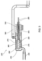
- recombinator 245 comprises a housing 250 which defines a reaction chamber 255 within its interior.
- Reaction chamber 255 is continuous with recombinator inlet 240 and a recombinator outlet 260.
- Reaction chamber 255 contains a catalyst 265 disposed on the surface of a substrate 270.
- Catalyst 265 may be selected from any material which is effective at catalysing the conversion of gaseous bromine and hydrogen into hydrogen bromide.
- catalyst 265 will be selected from precious metals and precious metal alloys such as platinum, ruthenium, palladium and rhodium.
- catalyst 265 is formed from a suitable combination of one or more of these elements bonded to the surface of substrate 270.
- Substrate 270 provides a physical support for catalyst 265 and is preferably manufactured from a ceramic material such as alumina (Al 2 O 3 ), SiO 2 or MgO.
- substrate 270 is constructed from alumina. It is preferred, although not essential, that substrate 270 is porous and thereby presents a larger surface area for the deposition of catalyst 265 as this provides for faster reactions rates.
- Substrate 270 surrounds a heating tube 275 which contains a heating element 280.
- Heating tube 275 is impermeable to the vapours within reaction chamber 255 to prevent the ingress of hydrogen bromide/hydrobromic acid which could damage heating element 280.
- Heating tube 275 is constructed from materials which are impermeable to the vapours discussed and have reasonable thermal conduction properties such as glass or ceramics such as Al 2 O 3 , SiO 2 and MgO.
- Heating element 280 sits within and substantially fills the volume of heating tube 275 and enables heating tube 275 to attain catalyst temperatures of between 130°C to 250°C. Heating catalyst 265 in this manner both further increases the rate of the hydrobromic acid forming reaction and keeps catalyst 265 dry to reduce the chances of it becoming saturated with corrosive liquid hydrobromic acid.
- Heating element 280 is connected to a power source via electrical connectors 285.
- Heating tube 275 and hence heating element 280 and electrical connectors 285 pass through a plug 300, which may take the form of a Teflon plug, to keep reaction chamber 255 airtight. Plug 300 may be inserted into recombinator 245 with a seal 305, such as an O-ring, to ensure sealing engagement.
- recombinator outlet 260 is seen to emerge from recombinator 245 on an opposite side to recombinator inlet 240 and enables the minimal amounts of unreacted hydrogen and bromine, as well as the newly formed hydrogen bromide/hydrobromic acid, to exit reaction chamber 255.
- Recombinator outlet 260 connects with a discharge tube 290 which, at its lower extent, ends in zinc electrolyte gas space 210.
- discharge tube 290 is seen to be intersected by one or more electrolyte flow tubes 295 and so electrolyte being returned to the zinc electrolyte tank via flow tubes 295 (indicated by arrows in FIG.
- discharge tube 290 is allowed to mix with the products exiting reaction chamber 255 through recombinator outlet 260.
- the electrolyte is caused to be returned to the zinc electrolyte tank through discharge tube 290 by the action of a zinc electrolyte pump (not shown in the figures).
- the zinc electrolyte pump will be operational and so electrolyte which has passed through the electrode stack or through a bypass tube is returned to zinc electrolyte gas space 210 and then the zinc electrolyte tank by being pumped through electrolyte flow tubes 295 and into discharge tube 290.
- electrolyte is flowing down discharge tube 290, past the point where it is intersected by recombinator outlet 260, and is returned to the zinc electrolyte tank.
- This flow action down discharge tube 290 creates a pressure differential and means that the pressure at the upper extent of discharge tube 290, in the region of its connection with recombinator outlet 260, is lower than that at its lower extent in zinc electrolyte gas space 210.
- This region of low,pressure creates a driving force to actively draw the gaseous contents, and any minor amounts of condensate which may form, out of recombinator outlet 260 and into discharge tube 290 to be returned into the zinc electrolyte tank to maintain the correct pH balance within the zinc-, bromine battery.
- bromine supply line 230 takes the form of a small bypass tube originating from the bromine pump and receiving its bromine rich electrolyte supply therefrom.
- reaction chamber 255 Once inside reaction chamber 255 the gaseous hydrogen and bromine come into contact with catalyst 265 disposed on the surface of substrate 270 which is heated by heating tube 275 containing heating element 280.
- Catalyst 265 speeds up the conversion of hydrogen and bromine into hydrogen bromide which, upon dissolving in an aqueous environment either in condensed vapour within recombinator outlet 260 or in electrolyte within discharge tube 290, forms hydrobromic acid. Maintaining catalyst 265 at an elevated temperature aids in keeping it dry, so reducing the likelihood of a build up of corrosive liquids on its surface.
- the resultant hydrogen bromide formed by the action of catalyst 265 is then drawn into recombinator outlet 260 and into discharge tube 290, as previously described.
- the present invention has provided a recombinator for a flowing electrolyte battery comprising a housing defining a reaction chamber for receiving a bromine source and a hydrogen source, and a catalyst within the reaction chamber to catalyse the formation of hydrogen bromide from the bromine source and the hydrogen source; wherein a liquid flow is prevented from entering the reaction chamber.
- the liquid flow (of bromine and/or electrolyte) is prevented from entering the reaction chamber by a combination of the orientation of the recombinator inlet, the use of a bromine evaporator providing entry for bromine into the recombinator inlet to ensure it is in gaseous form and a substrate for the catalyst which is heated by a heating element to substantially prevent condensation on said catalyst.
- the driving force for entry of gaseous components into the recombinator also ensures that reactants pass through the recombinator and outlet tube sufficiently quickly that significant amounts of condensation are avoided.
- the orientation of the recombinator inlet may be any one of a number of positions so long as at least a portion of its length prevents the flow of liquid into the reaction chamber. The particular orientation will depend upon the orientation of the reaction chamber itself. In one embodiment, at least a portion of the recombinator inlet is oriented substantially at right angles to the direction of flow of reactants and products through the reaction chamber. In another embodiment, for example when the reaction chamber itself is oriented vertically, then at least a portion of the recombinator inlet will extend substantially in alignment with the direction of flow of reactants and products through the reaction chamber.
- the present invention provides distinct advantages over the prior art in terms of the use of the zinc electrolyte pump as the driving force to draw reactants into recombinator 245 and reaction products out.
- This design means that when the zinc-bromine battery is not operational, and the zinc electrolyte pump is turned off, the flow of reactants into recombinator 245 is effectively halted and a build up of corrosive hydrobromic acid reaction product in the vicinity of catalyst 265 is prevented. This extends the lifetime of catalyst 265 and further lessens the risk of any portion of catalyst 265 finding its way into the circulating electrolyte paths.
Landscapes
- Life Sciences & Earth Sciences (AREA)
- Engineering & Computer Science (AREA)
- Manufacturing & Machinery (AREA)
- Sustainable Development (AREA)
- Sustainable Energy (AREA)
- Chemical & Material Sciences (AREA)
- Chemical Kinetics & Catalysis (AREA)
- Electrochemistry (AREA)
- General Chemical & Material Sciences (AREA)
- Hybrid Cells (AREA)
Applications Claiming Priority (2)
| Application Number | Priority Date | Filing Date | Title |
|---|---|---|---|
| AU2009905192A AU2009905192A0 (en) | 2009-10-23 | Recombinator for flowing electrolyte battery | |
| PCT/AU2010/001413 WO2011047441A1 (en) | 2009-10-23 | 2010-10-22 | Recombinator for flowing electrolyte battery |
Publications (3)
| Publication Number | Publication Date |
|---|---|
| EP2491610A1 EP2491610A1 (en) | 2012-08-29 |
| EP2491610A4 EP2491610A4 (en) | 2015-04-22 |
| EP2491610B1 true EP2491610B1 (en) | 2017-06-28 |
Family
ID=43899739
Family Applications (1)
| Application Number | Title | Priority Date | Filing Date |
|---|---|---|---|
| EP10824323.9A Not-in-force EP2491610B1 (en) | 2009-10-23 | 2010-10-22 | Recombinator for flowing electrolyte battery |
Country Status (8)
| Country | Link |
|---|---|
| US (1) | US9099722B2 (https=) |
| EP (1) | EP2491610B1 (https=) |
| JP (1) | JP5649140B2 (https=) |
| CN (1) | CN102640346B (https=) |
| AU (1) | AU2010310894B2 (https=) |
| MY (1) | MY158937A (https=) |
| NZ (1) | NZ598798A (https=) |
| WO (1) | WO2011047441A1 (https=) |
Families Citing this family (7)
| Publication number | Priority date | Publication date | Assignee | Title |
|---|---|---|---|---|
| US6218122B1 (en) | 1998-06-19 | 2001-04-17 | Rosetta Inpharmatics, Inc. | Methods of monitoring disease states and therapies using gene expression profiles |
| DE102007061662A1 (de) * | 2007-12-18 | 2009-06-25 | Vb Autobatterie Gmbh & Co. Kgaa | Akkumulator |
| US8916281B2 (en) | 2011-03-29 | 2014-12-23 | Enervault Corporation | Rebalancing electrolytes in redox flow battery systems |
| US20140017544A1 (en) * | 2012-07-16 | 2014-01-16 | Primus Power Corporation | Hydrogen Recombinator |
| US8993183B2 (en) | 2012-12-31 | 2015-03-31 | Enervault Corporation | Operating a redox flow battery with a negative electrolyte imbalance |
| US8980454B2 (en) | 2013-03-15 | 2015-03-17 | Enervault Corporation | Systems and methods for rebalancing redox flow battery electrolytes |
| CN111200154A (zh) * | 2020-01-10 | 2020-05-26 | 西南交通大学 | 一种多卤化物-铬液流电池 |
Family Cites Families (19)
| Publication number | Priority date | Publication date | Assignee | Title |
|---|---|---|---|---|
| US4414292A (en) * | 1982-01-29 | 1983-11-08 | Energy Development Associates, Inc. | Metal halogen battery system |
| US4400446A (en) | 1982-03-12 | 1983-08-23 | Energy Development Associates, Inc. | Halogen hydrate storage device for mobile zinc-chloride battery systems |
| US4386140A (en) | 1982-04-16 | 1983-05-31 | Energy Development Associates, Inc. | Multiple stage multiple filter hydrate store |
| US4540639A (en) * | 1982-12-01 | 1985-09-10 | Exxon Research & Engineering Company | Method and apparatus for maintaining the pH in zinc-bromine battery systems |
| CA1202071A (en) * | 1982-12-01 | 1986-03-18 | Patrick G. Grimes | Method and apparatus for maintaining the ph in zinc- bromine battery systems |
| JPS60257078A (ja) * | 1984-06-01 | 1985-12-18 | Furukawa Electric Co Ltd:The | 亜鉛−塩化物電池 |
| JPS61151977A (ja) | 1984-12-25 | 1986-07-10 | 松下電工株式会社 | ヘアードライヤの電源コード接続構造 |
| JPS61151971A (ja) * | 1984-12-25 | 1986-07-10 | Mitsui Eng & Shipbuild Co Ltd | 電池装置 |
| JPH0210672A (ja) * | 1988-06-29 | 1990-01-16 | Furukawa Electric Co Ltd:The | 亜鉛−塩化物電池 |
| JPH02135671A (ja) * | 1988-11-16 | 1990-05-24 | Toyota Motor Corp | 金属−ハロゲン電池 |
| JPH02256179A (ja) * | 1989-03-28 | 1990-10-16 | Toyota Motor Corp | 電解液循環式亜鉛‐臭素電池 |
| AT399245B (de) * | 1992-09-01 | 1995-04-25 | Elin Energieanwendung | Zink-brom-batterie mit umlaufenden elektrolyten |
| US5439757A (en) * | 1992-10-14 | 1995-08-08 | National Power Plc | Electrochemical energy storage and/or power delivery cell with pH control |
| US5628887A (en) * | 1996-04-15 | 1997-05-13 | Patterson; James A. | Electrolytic system and cell |
| WO2001091207A1 (fr) * | 2000-05-22 | 2001-11-29 | Asahi Kasei Kabushiki Kaisha | Separateur de cellule secondaire au zinc et au brome, et procede de realisation |
| US6455187B1 (en) * | 2000-10-03 | 2002-09-24 | Premium Power Acquisition Corporation | Recombinator for the re-acidification of an electrolyte stream in a flowing electrolyte zinc-bromine battery |
| US20030113615A1 (en) * | 2001-12-13 | 2003-06-19 | Gerd Tomazic | Recombinator for the re-acidification of an electrolyte stream in a flowing electrolyte zinc-bromine battery |
| CN1870335A (zh) * | 2006-04-13 | 2006-11-29 | 复旦大学 | 基于溴离子传导的新型储能电池 |
| EP2130244B1 (en) * | 2007-03-28 | 2014-12-03 | RedFlow R&D Pty Ltd | Cell stack for a flowing electrolyte battery |
-
2010
- 2010-10-22 AU AU2010310894A patent/AU2010310894B2/en active Active
- 2010-10-22 EP EP10824323.9A patent/EP2491610B1/en not_active Not-in-force
- 2010-10-22 US US13/503,191 patent/US9099722B2/en active Active
- 2010-10-22 NZ NZ598798A patent/NZ598798A/en unknown
- 2010-10-22 CN CN201080047417.3A patent/CN102640346B/zh active Active
- 2010-10-22 JP JP2012534500A patent/JP5649140B2/ja not_active Expired - Fee Related
- 2010-10-22 WO PCT/AU2010/001413 patent/WO2011047441A1/en not_active Ceased
- 2010-10-22 MY MYPI2012700159A patent/MY158937A/en unknown
Non-Patent Citations (1)
| Title |
|---|
| None * |
Also Published As
| Publication number | Publication date |
|---|---|
| MY158937A (en) | 2016-11-30 |
| CN102640346B (zh) | 2016-01-13 |
| US20120202095A1 (en) | 2012-08-09 |
| EP2491610A4 (en) | 2015-04-22 |
| EP2491610A1 (en) | 2012-08-29 |
| NZ598798A (en) | 2014-03-28 |
| AU2010310894A1 (en) | 2012-04-12 |
| US9099722B2 (en) | 2015-08-04 |
| WO2011047441A1 (en) | 2011-04-28 |
| JP5649140B2 (ja) | 2015-01-07 |
| JP2013508896A (ja) | 2013-03-07 |
| AU2010310894B2 (en) | 2014-08-07 |
| CN102640346A (zh) | 2012-08-15 |
Similar Documents
| Publication | Publication Date | Title |
|---|---|---|
| EP2491610B1 (en) | Recombinator for flowing electrolyte battery | |
| EP2274781B1 (en) | Electrochemical cell, and particularly a metal fueled cell with non-parallel flow | |
| JP6316322B2 (ja) | 電気化学電池における水の回収/リサイクルシステム | |
| CN103199294B (zh) | 基于微流体的自呼吸式光催化无膜燃料电池 | |
| CN109148927B (zh) | 具有浸没微射流的空气自呼吸无膜微流体燃料电池 | |
| JP2005522846A (ja) | 燃料電池におけるガス輸送の制御 | |
| CN101997121A (zh) | 用于燃料电池的连续型多孔流体分配器 | |
| CN116770343A (zh) | 用于从电解介质中分离产物气体的设备 | |
| US20250034727A1 (en) | Electrolyser | |
| US20130316254A1 (en) | Energy system | |
| JP2013508896A5 (https=) | ||
| WO2002025755A2 (en) | Gas-evolving electrochemical cells | |
| CN106784955B (zh) | 氢氧燃料电池 | |
| EP2803102B1 (en) | A liquid electrolyte fuel cell system | |
| US7767326B2 (en) | Water controller system having stable structure for direct methanol fuel cell | |
| JP5581537B2 (ja) | 燃料電池用の吐出ヘッド | |
| WO2005050763A1 (en) | Microfluidic fuel cell system and method for portable energy applications | |
| US20140017544A1 (en) | Hydrogen Recombinator | |
| CN223576606U (zh) | 电解系统 | |
| Feng et al. | Microfluidic Flow Cells for Energy Conversion and Utilization | |
| CN113578010B (zh) | 能动式氢复合器及消氢系统 | |
| de Sá | Micro alcohol fuel cells towards autonomous electrochemical | |
| JP2026030386A (ja) | 光触媒セル及び水素ガス生成システム | |
| CN106784956B (zh) | 改进的氢氧燃料电池 | |
| WO2010041170A1 (en) | A rechargeable fuel cell system and a method for recharging a rechargeable fuel cell system |
Legal Events
| Date | Code | Title | Description |
|---|---|---|---|
| PUAI | Public reference made under article 153(3) epc to a published international application that has entered the european phase |
Free format text: ORIGINAL CODE: 0009012 |
|
| 17P | Request for examination filed |
Effective date: 20120320 |
|
| AK | Designated contracting states |
Kind code of ref document: A1 Designated state(s): AL AT BE BG CH CY CZ DE DK EE ES FI FR GB GR HR HU IE IS IT LI LT LU LV MC MK MT NL NO PL PT RO RS SE SI SK SM TR |
|
| DAX | Request for extension of the european patent (deleted) | ||
| RAP1 | Party data changed (applicant data changed or rights of an application transferred) |
Owner name: REDFLOW R&D PTY LTD |
|
| RA4 | Supplementary search report drawn up and despatched (corrected) |
Effective date: 20150325 |
|
| RIC1 | Information provided on ipc code assigned before grant |
Ipc: H01M 8/04 20060101ALI20150319BHEP Ipc: H01M 8/18 20060101AFI20150319BHEP |
|
| REG | Reference to a national code |
Ref country code: DE Ref legal event code: R079 Ref document number: 602010043356 Country of ref document: DE Free format text: PREVIOUS MAIN CLASS: H01M0010360000 Ipc: H01M0008180000 |
|
| GRAP | Despatch of communication of intention to grant a patent |
Free format text: ORIGINAL CODE: EPIDOSNIGR1 |
|
| STAA | Information on the status of an ep patent application or granted ep patent |
Free format text: STATUS: GRANT OF PATENT IS INTENDED |
|
| RIC1 | Information provided on ipc code assigned before grant |
Ipc: H01M 8/04791 20160101ALI20170223BHEP Ipc: H01M 8/04276 20160101ALN20170223BHEP Ipc: H01M 8/18 20060101AFI20170223BHEP Ipc: H01M 8/04186 20160101ALI20170223BHEP |
|
| RIC1 | Information provided on ipc code assigned before grant |
Ipc: H01M 8/04791 20160101ALI20170224BHEP Ipc: H01M 8/18 20060101AFI20170224BHEP Ipc: H01M 8/04186 20160101ALI20170224BHEP Ipc: H01M 8/04276 20160101ALN20170224BHEP |
|
| RIC1 | Information provided on ipc code assigned before grant |
Ipc: H01M 8/18 20060101AFI20170308BHEP Ipc: H01M 8/04791 20160101ALI20170308BHEP Ipc: H01M 8/04186 20160101ALI20170308BHEP Ipc: H01M 8/04276 20160101ALN20170308BHEP |
|
| RIC1 | Information provided on ipc code assigned before grant |
Ipc: H01M 8/18 20060101AFI20170315BHEP Ipc: H01M 8/04791 20160101ALI20170315BHEP Ipc: H01M 8/04276 20160101ALN20170315BHEP Ipc: H01M 8/04186 20160101ALI20170315BHEP |
|
| INTG | Intention to grant announced |
Effective date: 20170329 |
|
| GRAS | Grant fee paid |
Free format text: ORIGINAL CODE: EPIDOSNIGR3 |
|
| GRAA | (expected) grant |
Free format text: ORIGINAL CODE: 0009210 |
|
| STAA | Information on the status of an ep patent application or granted ep patent |
Free format text: STATUS: THE PATENT HAS BEEN GRANTED |
|
| AK | Designated contracting states |
Kind code of ref document: B1 Designated state(s): AL AT BE BG CH CY CZ DE DK EE ES FI FR GB GR HR HU IE IS IT LI LT LU LV MC MK MT NL NO PL PT RO RS SE SI SK SM TR |
|
| REG | Reference to a national code |
Ref country code: GB Ref legal event code: FG4D |
|
| REG | Reference to a national code |
Ref country code: CH Ref legal event code: EP |
|
| REG | Reference to a national code |
Ref country code: AT Ref legal event code: REF Ref document number: 905583 Country of ref document: AT Kind code of ref document: T Effective date: 20170715 |
|
| REG | Reference to a national code |
Ref country code: IE Ref legal event code: FG4D |
|
| REG | Reference to a national code |
Ref country code: DE Ref legal event code: R096 Ref document number: 602010043356 Country of ref document: DE |
|
| REG | Reference to a national code |
Ref country code: FR Ref legal event code: PLFP Year of fee payment: 8 |
|
| PG25 | Lapsed in a contracting state [announced via postgrant information from national office to epo] |
Ref country code: NO Free format text: LAPSE BECAUSE OF FAILURE TO SUBMIT A TRANSLATION OF THE DESCRIPTION OR TO PAY THE FEE WITHIN THE PRESCRIBED TIME-LIMIT Effective date: 20170928 Ref country code: GR Free format text: LAPSE BECAUSE OF FAILURE TO SUBMIT A TRANSLATION OF THE DESCRIPTION OR TO PAY THE FEE WITHIN THE PRESCRIBED TIME-LIMIT Effective date: 20170929 Ref country code: HR Free format text: LAPSE BECAUSE OF FAILURE TO SUBMIT A TRANSLATION OF THE DESCRIPTION OR TO PAY THE FEE WITHIN THE PRESCRIBED TIME-LIMIT Effective date: 20170628 Ref country code: FI Free format text: LAPSE BECAUSE OF FAILURE TO SUBMIT A TRANSLATION OF THE DESCRIPTION OR TO PAY THE FEE WITHIN THE PRESCRIBED TIME-LIMIT Effective date: 20170628 Ref country code: LT Free format text: LAPSE BECAUSE OF FAILURE TO SUBMIT A TRANSLATION OF THE DESCRIPTION OR TO PAY THE FEE WITHIN THE PRESCRIBED TIME-LIMIT Effective date: 20170628 |
|
| REG | Reference to a national code |
Ref country code: NL Ref legal event code: MP Effective date: 20170628 |
|
| REG | Reference to a national code |
Ref country code: LT Ref legal event code: MG4D |
|
| REG | Reference to a national code |
Ref country code: AT Ref legal event code: MK05 Ref document number: 905583 Country of ref document: AT Kind code of ref document: T Effective date: 20170628 |
|
| PG25 | Lapsed in a contracting state [announced via postgrant information from national office to epo] |
Ref country code: SE Free format text: LAPSE BECAUSE OF FAILURE TO SUBMIT A TRANSLATION OF THE DESCRIPTION OR TO PAY THE FEE WITHIN THE PRESCRIBED TIME-LIMIT Effective date: 20170628 Ref country code: NL Free format text: LAPSE BECAUSE OF FAILURE TO SUBMIT A TRANSLATION OF THE DESCRIPTION OR TO PAY THE FEE WITHIN THE PRESCRIBED TIME-LIMIT Effective date: 20170628 Ref country code: LV Free format text: LAPSE BECAUSE OF FAILURE TO SUBMIT A TRANSLATION OF THE DESCRIPTION OR TO PAY THE FEE WITHIN THE PRESCRIBED TIME-LIMIT Effective date: 20170628 Ref country code: RS Free format text: LAPSE BECAUSE OF FAILURE TO SUBMIT A TRANSLATION OF THE DESCRIPTION OR TO PAY THE FEE WITHIN THE PRESCRIBED TIME-LIMIT Effective date: 20170628 Ref country code: BG Free format text: LAPSE BECAUSE OF FAILURE TO SUBMIT A TRANSLATION OF THE DESCRIPTION OR TO PAY THE FEE WITHIN THE PRESCRIBED TIME-LIMIT Effective date: 20170928 |
|
| PG25 | Lapsed in a contracting state [announced via postgrant information from national office to epo] |
Ref country code: CZ Free format text: LAPSE BECAUSE OF FAILURE TO SUBMIT A TRANSLATION OF THE DESCRIPTION OR TO PAY THE FEE WITHIN THE PRESCRIBED TIME-LIMIT Effective date: 20170628 Ref country code: EE Free format text: LAPSE BECAUSE OF FAILURE TO SUBMIT A TRANSLATION OF THE DESCRIPTION OR TO PAY THE FEE WITHIN THE PRESCRIBED TIME-LIMIT Effective date: 20170628 Ref country code: SK Free format text: LAPSE BECAUSE OF FAILURE TO SUBMIT A TRANSLATION OF THE DESCRIPTION OR TO PAY THE FEE WITHIN THE PRESCRIBED TIME-LIMIT Effective date: 20170628 Ref country code: RO Free format text: LAPSE BECAUSE OF FAILURE TO SUBMIT A TRANSLATION OF THE DESCRIPTION OR TO PAY THE FEE WITHIN THE PRESCRIBED TIME-LIMIT Effective date: 20170628 Ref country code: AT Free format text: LAPSE BECAUSE OF FAILURE TO SUBMIT A TRANSLATION OF THE DESCRIPTION OR TO PAY THE FEE WITHIN THE PRESCRIBED TIME-LIMIT Effective date: 20170628 |
|
| PG25 | Lapsed in a contracting state [announced via postgrant information from national office to epo] |
Ref country code: SM Free format text: LAPSE BECAUSE OF FAILURE TO SUBMIT A TRANSLATION OF THE DESCRIPTION OR TO PAY THE FEE WITHIN THE PRESCRIBED TIME-LIMIT Effective date: 20170628 Ref country code: ES Free format text: LAPSE BECAUSE OF FAILURE TO SUBMIT A TRANSLATION OF THE DESCRIPTION OR TO PAY THE FEE WITHIN THE PRESCRIBED TIME-LIMIT Effective date: 20170628 Ref country code: IS Free format text: LAPSE BECAUSE OF FAILURE TO SUBMIT A TRANSLATION OF THE DESCRIPTION OR TO PAY THE FEE WITHIN THE PRESCRIBED TIME-LIMIT Effective date: 20171028 Ref country code: PL Free format text: LAPSE BECAUSE OF FAILURE TO SUBMIT A TRANSLATION OF THE DESCRIPTION OR TO PAY THE FEE WITHIN THE PRESCRIBED TIME-LIMIT Effective date: 20170628 Ref country code: IT Free format text: LAPSE BECAUSE OF FAILURE TO SUBMIT A TRANSLATION OF THE DESCRIPTION OR TO PAY THE FEE WITHIN THE PRESCRIBED TIME-LIMIT Effective date: 20170628 |
|
| REG | Reference to a national code |
Ref country code: DE Ref legal event code: R097 Ref document number: 602010043356 Country of ref document: DE |
|
| PG25 | Lapsed in a contracting state [announced via postgrant information from national office to epo] |
Ref country code: DK Free format text: LAPSE BECAUSE OF FAILURE TO SUBMIT A TRANSLATION OF THE DESCRIPTION OR TO PAY THE FEE WITHIN THE PRESCRIBED TIME-LIMIT Effective date: 20170628 |
|
| PLBE | No opposition filed within time limit |
Free format text: ORIGINAL CODE: 0009261 |
|
| STAA | Information on the status of an ep patent application or granted ep patent |
Free format text: STATUS: NO OPPOSITION FILED WITHIN TIME LIMIT |
|
| PG25 | Lapsed in a contracting state [announced via postgrant information from national office to epo] |
Ref country code: MC Free format text: LAPSE BECAUSE OF FAILURE TO SUBMIT A TRANSLATION OF THE DESCRIPTION OR TO PAY THE FEE WITHIN THE PRESCRIBED TIME-LIMIT Effective date: 20170628 |
|
| REG | Reference to a national code |
Ref country code: CH Ref legal event code: PL |
|
| 26N | No opposition filed |
Effective date: 20180329 |
|
| REG | Reference to a national code |
Ref country code: IE Ref legal event code: MM4A |
|
| PG25 | Lapsed in a contracting state [announced via postgrant information from national office to epo] |
Ref country code: LU Free format text: LAPSE BECAUSE OF NON-PAYMENT OF DUE FEES Effective date: 20171022 Ref country code: CH Free format text: LAPSE BECAUSE OF NON-PAYMENT OF DUE FEES Effective date: 20171031 Ref country code: LI Free format text: LAPSE BECAUSE OF NON-PAYMENT OF DUE FEES Effective date: 20171031 |
|
| REG | Reference to a national code |
Ref country code: BE Ref legal event code: MM Effective date: 20171031 |
|
| PG25 | Lapsed in a contracting state [announced via postgrant information from national office to epo] |
Ref country code: BE Free format text: LAPSE BECAUSE OF NON-PAYMENT OF DUE FEES Effective date: 20171031 Ref country code: SI Free format text: LAPSE BECAUSE OF FAILURE TO SUBMIT A TRANSLATION OF THE DESCRIPTION OR TO PAY THE FEE WITHIN THE PRESCRIBED TIME-LIMIT Effective date: 20170628 |
|
| PG25 | Lapsed in a contracting state [announced via postgrant information from national office to epo] |
Ref country code: MT Free format text: LAPSE BECAUSE OF NON-PAYMENT OF DUE FEES Effective date: 20171022 |
|
| REG | Reference to a national code |
Ref country code: FR Ref legal event code: PLFP Year of fee payment: 9 |
|
| PG25 | Lapsed in a contracting state [announced via postgrant information from national office to epo] |
Ref country code: IE Free format text: LAPSE BECAUSE OF NON-PAYMENT OF DUE FEES Effective date: 20171022 |
|
| PG25 | Lapsed in a contracting state [announced via postgrant information from national office to epo] |
Ref country code: HU Free format text: LAPSE BECAUSE OF FAILURE TO SUBMIT A TRANSLATION OF THE DESCRIPTION OR TO PAY THE FEE WITHIN THE PRESCRIBED TIME-LIMIT; INVALID AB INITIO Effective date: 20101022 |
|
| PG25 | Lapsed in a contracting state [announced via postgrant information from national office to epo] |
Ref country code: CY Free format text: LAPSE BECAUSE OF NON-PAYMENT OF DUE FEES Effective date: 20170628 |
|
| PG25 | Lapsed in a contracting state [announced via postgrant information from national office to epo] |
Ref country code: MK Free format text: LAPSE BECAUSE OF FAILURE TO SUBMIT A TRANSLATION OF THE DESCRIPTION OR TO PAY THE FEE WITHIN THE PRESCRIBED TIME-LIMIT Effective date: 20170628 |
|
| PGFP | Annual fee paid to national office [announced via postgrant information from national office to epo] |
Ref country code: DE Payment date: 20191008 Year of fee payment: 10 |
|
| PGFP | Annual fee paid to national office [announced via postgrant information from national office to epo] |
Ref country code: FR Payment date: 20191014 Year of fee payment: 10 |
|
| PG25 | Lapsed in a contracting state [announced via postgrant information from national office to epo] |
Ref country code: TR Free format text: LAPSE BECAUSE OF FAILURE TO SUBMIT A TRANSLATION OF THE DESCRIPTION OR TO PAY THE FEE WITHIN THE PRESCRIBED TIME-LIMIT Effective date: 20170628 |
|
| PGFP | Annual fee paid to national office [announced via postgrant information from national office to epo] |
Ref country code: GB Payment date: 20191018 Year of fee payment: 10 |
|
| PG25 | Lapsed in a contracting state [announced via postgrant information from national office to epo] |
Ref country code: PT Free format text: LAPSE BECAUSE OF FAILURE TO SUBMIT A TRANSLATION OF THE DESCRIPTION OR TO PAY THE FEE WITHIN THE PRESCRIBED TIME-LIMIT Effective date: 20170628 |
|
| PG25 | Lapsed in a contracting state [announced via postgrant information from national office to epo] |
Ref country code: AL Free format text: LAPSE BECAUSE OF FAILURE TO SUBMIT A TRANSLATION OF THE DESCRIPTION OR TO PAY THE FEE WITHIN THE PRESCRIBED TIME-LIMIT Effective date: 20170628 |
|
| REG | Reference to a national code |
Ref country code: DE Ref legal event code: R119 Ref document number: 602010043356 Country of ref document: DE |
|
| GBPC | Gb: european patent ceased through non-payment of renewal fee |
Effective date: 20201022 |
|
| PG25 | Lapsed in a contracting state [announced via postgrant information from national office to epo] |
Ref country code: DE Free format text: LAPSE BECAUSE OF NON-PAYMENT OF DUE FEES Effective date: 20210501 Ref country code: FR Free format text: LAPSE BECAUSE OF NON-PAYMENT OF DUE FEES Effective date: 20201031 |
|
| PG25 | Lapsed in a contracting state [announced via postgrant information from national office to epo] |
Ref country code: GB Free format text: LAPSE BECAUSE OF NON-PAYMENT OF DUE FEES Effective date: 20201022 |