EP2490969B1 - Strip material dispensing device - Google Patents
Strip material dispensing device Download PDFInfo
- Publication number
- EP2490969B1 EP2490969B1 EP10773458.4A EP10773458A EP2490969B1 EP 2490969 B1 EP2490969 B1 EP 2490969B1 EP 10773458 A EP10773458 A EP 10773458A EP 2490969 B1 EP2490969 B1 EP 2490969B1
- Authority
- EP
- European Patent Office
- Prior art keywords
- guide arm
- substrate
- frame
- crank shaft
- friction
- Prior art date
- Legal status (The legal status is an assumption and is not a legal conclusion. Google has not performed a legal analysis and makes no representation as to the accuracy of the status listed.)
- Active
Links
Images








Classifications
-
- B—PERFORMING OPERATIONS; TRANSPORTING
- B65—CONVEYING; PACKING; STORING; HANDLING THIN OR FILAMENTARY MATERIAL
- B65H—HANDLING THIN OR FILAMENTARY MATERIAL, e.g. SHEETS, WEBS, CABLES
- B65H39/00—Associating, collating, or gathering articles or webs
- B65H39/16—Associating two or more webs
-
- B—PERFORMING OPERATIONS; TRANSPORTING
- B65—CONVEYING; PACKING; STORING; HANDLING THIN OR FILAMENTARY MATERIAL
- B65H—HANDLING THIN OR FILAMENTARY MATERIAL, e.g. SHEETS, WEBS, CABLES
- B65H57/00—Guides for filamentary materials; Supports therefor
- B65H57/006—Traversing guides
-
- B—PERFORMING OPERATIONS; TRANSPORTING
- B65—CONVEYING; PACKING; STORING; HANDLING THIN OR FILAMENTARY MATERIAL
- B65H—HANDLING THIN OR FILAMENTARY MATERIAL, e.g. SHEETS, WEBS, CABLES
- B65H2220/00—Function indicators
- B65H2220/02—Function indicators indicating an entity which is controlled, adjusted or changed by a control process, i.e. output
-
- B—PERFORMING OPERATIONS; TRANSPORTING
- B65—CONVEYING; PACKING; STORING; HANDLING THIN OR FILAMENTARY MATERIAL
- B65H—HANDLING THIN OR FILAMENTARY MATERIAL, e.g. SHEETS, WEBS, CABLES
- B65H2220/00—Function indicators
- B65H2220/04—Function indicators for distinguishing adjusting from controlling, i.e. manual adjustments
-
- B—PERFORMING OPERATIONS; TRANSPORTING
- B65—CONVEYING; PACKING; STORING; HANDLING THIN OR FILAMENTARY MATERIAL
- B65H—HANDLING THIN OR FILAMENTARY MATERIAL, e.g. SHEETS, WEBS, CABLES
- B65H2220/00—Function indicators
- B65H2220/09—Function indicators indicating that several of an entity are present
-
- B—PERFORMING OPERATIONS; TRANSPORTING
- B65—CONVEYING; PACKING; STORING; HANDLING THIN OR FILAMENTARY MATERIAL
- B65H—HANDLING THIN OR FILAMENTARY MATERIAL, e.g. SHEETS, WEBS, CABLES
- B65H2220/00—Function indicators
- B65H2220/11—Function indicators indicating that the input or output entities exclusively relate to machine elements
-
- B—PERFORMING OPERATIONS; TRANSPORTING
- B65—CONVEYING; PACKING; STORING; HANDLING THIN OR FILAMENTARY MATERIAL
- B65H—HANDLING THIN OR FILAMENTARY MATERIAL, e.g. SHEETS, WEBS, CABLES
- B65H2301/00—Handling processes for sheets or webs
- B65H2301/40—Type of handling process
- B65H2301/43—Gathering; Associating; Assembling
- B65H2301/431—Features with regard to the collection, nature, sequence and/or the making thereof
- B65H2301/4315—Webs
- B65H2301/43151—Webs and ribbons, tapes or strips
-
- B—PERFORMING OPERATIONS; TRANSPORTING
- B65—CONVEYING; PACKING; STORING; HANDLING THIN OR FILAMENTARY MATERIAL
- B65H—HANDLING THIN OR FILAMENTARY MATERIAL, e.g. SHEETS, WEBS, CABLES
- B65H2403/00—Power transmission; Driving means
- B65H2403/90—Machine drive
- B65H2403/94—Other features of machine drive
- B65H2403/941—Manually powered handling device
-
- B—PERFORMING OPERATIONS; TRANSPORTING
- B65—CONVEYING; PACKING; STORING; HANDLING THIN OR FILAMENTARY MATERIAL
- B65H—HANDLING THIN OR FILAMENTARY MATERIAL, e.g. SHEETS, WEBS, CABLES
- B65H2511/00—Dimensions; Position; Numbers; Identification; Occurrences
- B65H2511/20—Location in space
-
- B—PERFORMING OPERATIONS; TRANSPORTING
- B65—CONVEYING; PACKING; STORING; HANDLING THIN OR FILAMENTARY MATERIAL
- B65H—HANDLING THIN OR FILAMENTARY MATERIAL, e.g. SHEETS, WEBS, CABLES
- B65H2701/00—Handled material; Storage means
- B65H2701/10—Handled articles or webs
- B65H2701/17—Nature of material
- B65H2701/176—Cardboard
- B65H2701/1762—Corrugated
Definitions
- This disclosure relates to an apparatus for dispensing strip materials onto a moving substrate, such as paper-like material in a laminating or corrugating machine.
- the apparatus includes a frame extending transversally of the substrate path, the frame supporting at least one guide arm and a guide arm positioning system.
- Each guide arm includes means for dispensing strip materials and can be independently moved along the frame by the guide arm positioning system.
- the guide arm positioning system includes at least one crank shaft coupled to a first end of the frame, such that each crank shaft can rotate about an independent axis per crank shaft.
- the guide arm positioning system also includes at least one friction drive means coupled to each crank shaft and to a corresponding guide arm, wherein each friction drive means depends on frictional contact between two surfaces to transfer rotational movement of a crank shaft to linear motion of a guide arm.
- Each guide arm is independently movable along the frame by rotation of a corresponding crank shaft.
- Each friction drive means can include one or more drive pulley and tail pulley pairs, and cables that extend around each pair of drive and tail pulleys and that are fixed to a guide arm therebetween.
- a friction braking means can also be included to hold the guide arms in position, which can include various members that can be pressed against components of the drive system to frictionally prevent their motion.
- the apparatus can also include a guide arm position feedback system that can include a magnet attached to each guide arm and a transducer attached to the frame which interact with a remote control panel to measure and display the location of the guide arms.
- a guide arm position feedback system can include a magnet attached to each guide arm and a transducer attached to the frame which interact with a remote control panel to measure and display the location of the guide arms.
- the apparatus can further include a substrate tracking and adjustment system that includes a controller, an actuator, and a sensor that can track the position of the substrate as it moves side to side from the normal substrate path and automatically adjust the position of the frame to match.
- a linear actuator can adjust the transversal location of the frame relative to the substrate in response to a signal from the substrate sensor means, thereby adjusting all of the mounted guide arms in unison.
- the sensor can sense the substrate position and transmit the position information to a controller that can send a command signal to the actuator to move the frame to be aligned with the substrate position. As the frame moves, so do the guide arms supported by the frame. This sensing, comparing, and adjusting loop can be done repeatedly to maintain the frame and guide arms in the desired position in relation to the substrate.
- Step one includes rotating at least one crank shaft coupled to a first end of a frame such that each crank shaft can rotate about an independent axis per crank shaft, the frame extending transversally of the substrate path, each rotating crank shaft thereby actuating a friction drive means, one friction drive means being coupled to each crank shaft and a corresponding guide arm, each friction drive means depending on frictional contact between two surfaces to transfer rotational movement of the crank shaft to linear motion of a guide ann, each friction drive means thereby moving the corresponding guide arm to a desired position along the frame, each guide arm having a supporting means to movably couple the guide ann to the frame and a dispensing means for dispensing strip materials onto the substrate.
- Step two includes using a guide arm position feedback means to automatically determine the transversal position of each guide arm in relation to a predetermined position and display the positions on a display device.
- Step three includes repeating steps one and two until the display device displays the desired positions
- the apparatus includes at least one strip material dispensing guide arm that may be independently adjustable transversely of the direction of movement of the substrate.
- the strip materials may be a ribbon material, such as tape, string and yarn, various web materials and various widths of material, particularly tapes that include an adhesive such as a hot melt adhesive, a hot melt pressure sensitive adhesive, a hot melt remoistenable adhesive, a water dispersible hot melt adhesive, a biodegradable hot melt adhesive or a repulpable hot melt adhesive, or heat activatable adhesives.
- an adhesive such as a hot melt adhesive, a hot melt pressure sensitive adhesive, a hot melt remoistenable adhesive, a water dispersible hot melt adhesive, a biodegradable hot melt adhesive or a repulpable hot melt adhesive, or heat activatable adhesives.
- the substrate may be a film, non-woven web, paper product, paper board, carton blank, box board, corrugated board or other sheet material or web material, all of various widths.
- the substrate processing machine may be a wet end, a dry end, or both a wet end and a dry end of a corrugation machine, a lamination machine, a carton press, a fiber reinforcement application machine, or other similar machines that processes a moving substrate.
- the substrate processing machine can process more than one substrate at the same time, for example, one above the other, and can combine more than one substrate into a single substrate during the processing.
- changing the position of any one or more of the dispensing guide arms is accomplished by turning a series of crankshafts located at a head end of the apparatus.
- a control box precisely displays the position of each of the guide arms. This combination of moving the guide arms from the head end of the apparatus and the precise guide arm position readout enables apparatus setup and fine calibration without removing the apparatus from the substrate processing machine.
- Change in the position of the strip materials is dictated by the desired position of the strip material on the substrate and the later manufacturing of the substrate. Depending on the strength of the strip material, the same will be a suitable transverse reinforcement of the substrate or serve as a tear strip affording ease in opening the container to be formed from the substrate.
- the apparatus is adapted to be positioned in various locations within a substrate processing machine 4.
- FIG. 1 shows one possible location.
- An apparatus 200 corresponding to the apparatus 2, can additionally be positioned in the substrate processing machine 4, for example above or below the apparatus 2, as shown in FIGS 2 and 17 .
- the apparatus 200 can be positioned on the opposite side of the substrate 6 to simultaneously apply strip materials 8 to the other side of the substrate 6. In other embodiments, the apparatus 200 can be positioned to apply strip materials to a second substrate.
- the apparatus 200 can be used, for example, when strip materials are to be applied between different layers of a laminated substrate, such as in the manufacturing of "double wall” or “triple wall” corrugated board, and/or when strip materials are to be applied both between layers of a substrate and on an outer surface of the same substrate. Since the apparatus 2 is similar to the apparatus 200, only the apparatus 2 is described further.
- two or more upright support towers 10 can hold the apparatus 2 in a generally horizontal position at a desired height above the ground. Each of these upright support towers 10 can be mounted on wheels 12 for increased mobility.
- the apparatus 2 and towers 10 can be wheeled in and out of the substrate processing machine 4.
- a portion of the apparatus 2 e.g. a guide track 110, can be fixed to and supported by the substrate processing machine 4, and one or more of the upright support towers can then be removed.
- the upright support towers 10 can hold the apparatus 2 within the substrate processing machine 4 during operation and the apparatus 2 is not attached to the machine 4.
- An extension member 14 can also be included to connect the apparatus 2 to an upright support tower 10 such that the tower can be located farther away from the laminating machine.
- the length of the extension member 14 can be adjustable, and in one embodiment, the extension member 14 has a hollow cross section.
- the apparatus 2 includes an elongated frame 16.
- the frame 16 can be rectangular in cross section and can be constructed of aluminum.
- the frame 16 has a cross-sectional width of about 5.0 to 7.0 inches, and a cross-section height of about 4.25 inches.
- the frame 16 supports and encloses many components of the apparatus 2, shielding them from starch and other contaminants.
- the frame 16 supports one or more guide arms 18 that can be mounted in a series along the length of the frame 16.
- the frame 16 can also include a guide rail 20 fixed to the frame 16.
- Each guide arm 18 can include a component for coupling the guide ann 18 to the guide rail 20, for example a low friction sliding or rolling device, and in particular a linear bearing 22, which mates to the guide rail 20.
- Each guide arm 18 can have full range of the guide rail 20.
- the frame 16 and guide rail 20 can extend transversally beyond the edges of the substrate 6 such that the guide arms 16 can be positioned beyond the edges of the substrate 6.
- the guide arms 18 include pulleys 24 for receiving strip materials 8 that can be fed to the guide arms 18 transversely of the substrate from a remote supply 26 and then dispensed onto the substrate 6 for attachment and lamination thereto.
- the frame 16 with mounted guide arms 18 and pulleys 24 can have a total cross-sectional width of about 12.1 inches and a total cross-sectional height of about 6.6 inches.
- a guide arm moving and holding assembly 30 can be located at an end of the frame 16 generally separate from the portion of the frame where the guide arms 18 are mounted.
- the guide arm moving and holding assembly 30 can include at least one, and preferably a series of series of crank shaft(s) 32, head pulley(s) 34, cable(s) 36, and brake system(s) 38.
- crank shafts 32 arc rotably supported by the sides 42 of the frame 16 along parallel, horizontal axes. Pairs of shafts can be supported by the frame 16, side by side along the same axis.
- a center member 40 of the frame 16 is vertically disposed between the two crank shafts 32 and supports the inner ends of both crank shafts 32 such that they can rotate independently.
- the outer ends of the crank shafts 32 pass through opposite side walls 42 of the frame 16 and are connected to drive mechanisms 44.
- the drive mechanisms 44 can be manual cranks or automated devices, such as electric motors or actuators.
- a head pulley 34 is fixed to each crank shaft 32 within the frame 16 such that the head pulley 34 rotates with the crank shaft 32.
- Each cable 36 is secured to a corresponding guide arm 18 and makes a closed loop wrapping around a head pulley 32 and a tail pulley 46.
- the tail pulley assembly 48 shown in FIGS. 7a and 7b , is supported by the frame side walls 42 at the opposite end as the head pulleys 34.
- the tail pulley assembly 48 includes a series of independently rotable idler pulleys 46 that can be mounted on a common shaft 50 that is parallel to the crank shafts 32.
- the cable-pulley system is a friction-drive system that relies on the tension of the cable 36 strained around the head pulley 34 to move and hold the guide arms 18 in their desired positions.
- Tension can be necessary to prevent the cable 36 from slipping on the pulley 34 when the guide arms 18 exert a force on the cable 36, such as from a residual tension of the strip material 8 or an occasional jerk resulting from the splicing of two ends of running strip material 8.
- Tension can also be necessary to prevent the cable 36 from slipping on the pulley 34 when the crank shaft 32 is turned to move a guide arm 18 to a desired position.
- the frictional resistance generated can be the product of the tension force multiplied by the coefficient of static friction between the cable and pulley materials.
- the functional resistance of the cable 36 on the pulley 34 and the angle subtending the arc of contact between the pulley 34 and tension element are the primary factors that affect the design and performance of the cable-pulley friction-drive systems.
- An alternative to the cable-pulley friction-drive system which relies on the tension of a cable strained around a pulley to move and hold guide arms in their desired positions, is a chain-sprocket direct-drive system, which relies on intimately interlocking contact between chain links and sprocket teeth to move and hold guide arms to desired positions.
- tension is not required to prevent the chain from slipping on the sprocket when moving a guide arm to the desired position or when guide arms exert a force on the chain.
- Other direct-drive systems include gear and threaded rod drives that also rely on the intimate interlocking contact between drive elements to provide the desired motive force.
- each brake system 38 includes a horseshoe-shaped member 64, shown in FIG. 8a - 8c , that wraps around a portion of a corresponding head pulley 34. This member moves into contact with and frictionally retards the rotation of the head pulley 34 when an attached brake lever 66 is actuated.
- One end of the horseshoe-shaped member 64 can be fixed to the frame 16 while the other end protrudes through the frame 16 and couples to the brake lever 66.
- the brake lever 66 can include a cam portion and can be coupled to the frame 16 such that the brake lever 66 can be actuated, as shown in FIG.
- the brake system 38 can be arranged to hold the head pulley 34 in place when the lever 66 is actuated and keep the head pulley 34 stationary without maintained pressure on the lever 66.
- the brake systems 38 can include a similar horseshoe-shaped friction member 64 that is biased, such as by a spring 68, to be continually pressed against a head pulley 34.
- the constant static friction force generated by the biased friction member 64 and the head pulley 34 can be sufficient to keep the guide arm 18 stationary against vibrations and forces applied to the guide arm 18 during operation.
- the constant friction force can be weak enough, however, to be overcome by manual or mechanized turning of the crank shaft 32. In this embodiment, the brake systems 38 do not need to be applied and disengaged or otherwise adjusted during operation.
- the brake systems 38 can include a clutch brake system 70 mounted on each crank shaft 32.
- the clutch brake system 70 can include a disk-shaped back plate 72 mounted rotably on the crank shaft 32.
- One or more springs 74 can be fixed at one end to the back plate 72, and fixed at the other end to a clutch disk 76.
- the clutch disk 76 is also mounted rotably on the crank shaft 32, between the back plate 72 and the head pulley 34.
- the surface of the clutch disk 76 facing the head pulley 34 is lined with a friction pad 78 that can be pressed against the side of the head pulley 34 by the springs 74, as shown in FIG. 10 .
- the brake systems 38 can include a shaft brake 80.
- Each crank shaft 32 can be threaded at a location 82 near a side wall 42 of the frame 16.
- a nut 84 can be threaded onto the crank shaft 32.
- the nut 84 can be rotated such that the nut 84 moves along the crank shaft 32 and presses against a surface of the frame 16, such as the side wall 42.
- a drive mechanism 44 (not shown in FIG. 12 ) can be coupled to the end portion of the crank shaft 32 shown in FIG. 12 as having a square cross-section.
- Each of these brake system embodiments can create a friction-brake system that relies exclusively or primarily on the friction force between a surface of a friction member, such as the horseshoe-shaped member 64, the brake pad 78, or the brake nut 84, and a surface of a moving component of the drive system, such as a head pulley 34 or a crank shaft 32, to keep the guide arms 18 8 in their desired positions.
- the friction force generated to restrict the motion of arm guide arm is a product of a normal force exerted upon the friction member multiplied by the coefficient of friction between the friction member and the drive system component.
- the normal force can be supplied by manual pressure transferred to the friction member through a suitable device, such as a lever or spring system.
- the apparatus 2 can include a system for determining the position of the guide arms 18 transversely of the substrate direction of movement or the machine direction of the substrate 6.
- the linear bearing 22 of each guide arm 18 can have a magnet 88 mounted to it that cooperates with a transducer 90, as shown in FIG. 3 .
- the frame 16 supports the transducer 90 to afford a reading as to the position of the guide arms 18 with respect to the frame 16.
- the transducer 90 can be connected to a control panel 92, shown in FIG. 13 , having a display 94 providing a numeric digital readout giving the location along the frame 16 of the guide arms 18.
- the control panel 92 can have buttons 96 for user input, such as to select which arm 18 to monitor.
- the control panel 92 can be remotely located, and is mounted on an upright support tower 10 in one embodiment.
- a cable 98 connecting the transducer 90 to the control panel 92 can be routed through the frame 16 and through the hollow extension member 14, thereby keeping the cable 98 safe from harm.
- the magnets 88 cooperate with the transducer 90 to afford a signal in response to a current pulse sent from the control panel 92 along the transducer 90.
- the signal from each arm 18 can be discerned by the electronics in the control panel 92 to calculate the distance any particular guide arm 18 is from the predetermined "0" and the numeric value can then be displayed on the display 94.
- the transducer 90 and control panel 92 operation allows an operator to view the precise location of any guide arm 18.
- the control circuitry can trigger the transducer 90 to send a current pulse down a wire held inside the transducer 90.
- the current in the wire can then create an electric field about the wire.
- the electrical field of the wire interacts with the magnetic field of the magnet 88 on the guide arm 18. This interaction creates a torque in the wire producing a signal by the arm 18.
- the electronics of the transducer 90 calculate how long in time it was from when the current pulse was sent down the wire to when the reaction signal in the wire is sensed.
- the position of the guide arm 18 is discerned and the distance is calculated from the present "0" and a numeric value is displayed on the display of the control panel 92.
- the electronics can be designed to discern which magnet 88 from which to read the electric field-magnet field location signal. The operator then has a precise position reading and can adjust the arms 18 as necessary by rotating appropriate crank shafts 32.
- a substrate tracking and adjustment system 100 including a substrate sensor 102, control panel 92, and actuator 106 can be used to track the position of the substrate 6 as it moves side to side from the normal substrate path or position.
- the substrate tracking and adjustment system 100 is used to maintain the position of a frame 16 in relation to the substrate 6.
- the substrate tracking sensor 102 can be placed somewhere on the substrate processing machine 4, such as upstream from the apparatus 2 as shown in FIG. 1 , or the tracking sensor 102 can be affixed to the apparatus 2, preferably at a stationary location.
- the substrate sensor or sensors 102 can include laser, camera, proximity, pneumatic, ultrasonic, photo, optical, or other suitable sensing means.
- a movable end 120 of a linear actuator 106 can be secured to the frame 16 via an actuator-frame bracket 118 and a fixed end 122 of the actuator 106 can be secured to a guide track 110 via an actuator-track bracket 116.
- the actuator 106 can be driven hydraulically, pneumatically, magnetically, by a motor, or by other suitable driving means.
- the frame 16 can be mounted to the guide track 110 on two or more pairs of guide rollers 112, shown in detail in FIG. 16 , so as to allow the frame 16 to freely move along the length of the guide track I 10 if the frame 16 were not secured to the linear actuator 106.
- the pairs of guide rollers 112 2 can be fixed to the frame side wall 42 via guide roller brackets 124.
- the frame side wall 42 can be provided with multiple mounting locations along its length such that the guide roller brackets 124 can be attached at varying distance apart from each other.
- the actuator 106 can move the frame 16 on the guide track 110 by extending or contracting.
- the guide track 110 can be attached to a stationary object, such as a frame of the substrate processing machine 4, via a track bracket 114.
- the apparatus 2 including between one to eight guide arms 18, friction drive systems, horseshoe-type friction brake systems 38, linear bearings 22 and magnets 88, plus the transducer 90, guide rollers 112 and track brackets 114, and other necessary components, but not including the extension member 14, upright support towers 10, or guide track 110, can weigh 130 lbs to 165 lbs, depending on the number of guide arms and related systems installed.
- the installation of the apparatus 2 with the substrate tracking and adjustment system 100 into the operational position within a substrate processing machine 4 can be accomplished by first installing the guide track 110 and the actuator-track bracket 116 onto a stationary structural component of the substrate processing machine 4 via one or more tack brackets 114.
- the apparatus 2 can be wheeled on two upright support towers 10, as shown in FIG. 2 , into a position where the a first pair of guide rollers 112 are adjacent to an end of the guide track 110.
- the first pair of guide rollers 112 are installed onto the guide track 110 by allowing end of the guide track 110 to move between the first pair of guide rollers 112.
- one of the upright support towers 10 are removed and the guide track 110 supports the mounted end of the apparatus 2.
- the apparatus 2 is further rolled into the machine 4 until the second set of guide track rollers 112 mount onto the end of the guide track 110.
- the fixed end 122 of the linear actuator 106 is attached to the actuator track bracket 116.
- the substrate sensor 102 can detect the transversal position of the substrate 6. The substrate sensor 102 can then transmit the substrate position information to a controller 104. The control panel 92 can then compare the substrate position to the frame's preset position. If the substrate position is not aligned to the preset frame position, the control panel 92 can send a command signal to the actuator 106 to move the frame 16 to be aligned with the substrate position. As the frame 16 is moved along the guide track 110, each of the guide arms 18 mounted on the frame 16 are simultaneously moved the same distance. This sensing, comparing, and adjusting loop can be done continuously to maintain the frame 16 and guide arms 18 in the desired position in relation to the substrate 6.
- the strip materials 8 are taken from a bulk source and threaded through or around various strip guides 130 attached to the upright support tower 10, as shown in FIG. 17 .
- the strip materials are threaded around guide arm pulleys 24 and attached to the substrate 6.
- the guide arms need not be in desired transversal positions along the frame prior to attaching the strip materials to the substrate or prior to the substrate commencing movement through the machine. The guide arms can be adjusted while the substrate is moving and the strip materials are being dispensed.
- the corresponding brake systems 38 are first loosened, if needed, and then the user turns the corresponding drive mechanisms 44, which can be hand cranks, which in turn rotate crank shafts 32 and attached drive pulleys 34.
- the rotating drive pulleys 34 in coordination with the tail pulleys 46, moves cables 36 about a loop. When the cables 36 move, they pull the connected guide arms 18, which slide along the frame via the guide rail 20 on bearings 22.
- each guide arm interacts with the transducer 90 and send a signal to the control panel 92 signifying the location of each guide arm 18 in relation to a predetermined "0" location along the frame.
- the user can then interface with the buttons 96 and display 94 to select and read the location of each guide arm. If the guide arms are not in the desired positions, the user can then repeat these steps to adjust the guide arm positions to be more precise.
- the brake systems 38 can optionally be applied to hold them in place.
- the user can also manually hold the drive mechanisms 44 to hold the guide arms 16 in place.
- the brake systems 38 can be applied by various methods as described above, such as actuating levers or turning nuts.
- the brake lever 66 can be rotated towards the frame side wall 42, thereby employing a cam at the base of the lever 66 to pull the attached horseshoe member 64 downward and into frictional contact with the head pulley 34.
- the strip material application process can commence.
- the substrate tracking and adjustment system can optionally be used to automatically make transversal adjustments to all the guide arms in unison in reaction to side-to-side changes in the position of the moving substrate.
- these steps can repeated to re-adjust the guide arms, for example when there is an order change to manufacture a different product. All these steps can be done without removing the apparatus from the substrate processing machine or stopping the movement of the substrate.
Landscapes
- Coating Apparatus (AREA)
- Transmission Devices (AREA)
- Making Paper Articles (AREA)
- Advancing Webs (AREA)
- Engineering & Computer Science (AREA)
- Mechanical Engineering (AREA)
- Registering, Tensioning, Guiding Webs, And Rollers Therefor (AREA)
- Bending Of Plates, Rods, And Pipes (AREA)
Description
- This disclosure relates to an apparatus for dispensing strip materials onto a moving substrate, such as paper-like material in a laminating or corrugating machine.
-
U.S. Patent Nos. 6,705,500 ;5,759,339 ;7,222,653 and7,255,255 ; and Canadian Patent No.2,342,495 disclose embodiments of strip material dispensing machines. - In one embodiment disclosed herein there is described an apparatus for dispensing strip materials onto one or more moving substrates. The apparatus includes a frame extending transversally of the substrate path, the frame supporting at least one guide arm and a guide arm positioning system. Each guide arm includes means for dispensing strip materials and can be independently moved along the frame by the guide arm positioning system. The guide arm positioning system includes at least one crank shaft coupled to a first end of the frame, such that each crank shaft can rotate about an independent axis per crank shaft. The guide arm positioning system also includes at least one friction drive means coupled to each crank shaft and to a corresponding guide arm, wherein each friction drive means depends on frictional contact between two surfaces to transfer rotational movement of a crank shaft to linear motion of a guide arm. Each guide arm is independently movable along the frame by rotation of a corresponding crank shaft.
- Each friction drive means can include one or more drive pulley and tail pulley pairs, and cables that extend around each pair of drive and tail pulleys and that are fixed to a guide arm therebetween. A friction braking means can also be included to hold the guide arms in position, which can include various members that can be pressed against components of the drive system to frictionally prevent their motion.
- The apparatus can also include a guide arm position feedback system that can include a magnet attached to each guide arm and a transducer attached to the frame which interact with a remote control panel to measure and display the location of the guide arms.
- The apparatus can further include a substrate tracking and adjustment system that includes a controller, an actuator, and a sensor that can track the position of the substrate as it moves side to side from the normal substrate path and automatically adjust the position of the frame to match. In one embodiment, a linear actuator can adjust the transversal location of the frame relative to the substrate in response to a signal from the substrate sensor means, thereby adjusting all of the mounted guide arms in unison. The sensor can sense the substrate position and transmit the position information to a controller that can send a command signal to the actuator to move the frame to be aligned with the substrate position. As the frame moves, so do the guide arms supported by the frame. This sensing, comparing, and adjusting loop can be done repeatedly to maintain the frame and guide arms in the desired position in relation to the substrate.
- Also disclosed herein is a process that includes three steps for preparing to dispense strip materials onto a moving substrate. Step one includes rotating at least one crank shaft coupled to a first end of a frame such that each crank shaft can rotate about an independent axis per crank shaft, the frame extending transversally of the substrate path, each rotating crank shaft thereby actuating a friction drive means, one friction drive means being coupled to each crank shaft and a corresponding guide arm, each friction drive means depending on frictional contact between two surfaces to transfer rotational movement of the crank shaft to linear motion of a guide ann, each friction drive means thereby moving the corresponding guide arm to a desired position along the frame, each guide arm having a supporting means to movably couple the guide ann to the frame and a dispensing means for dispensing strip materials onto the substrate. Step two includes using a guide arm position feedback means to automatically determine the transversal position of each guide arm in relation to a predetermined position and display the positions on a display device. Step three includes repeating steps one and two until the display device displays the desired positions of the guide arms.
-
-
FIG. 1 is a top plan view of a strip material dispensing and positioning apparatus installed in a substrate processing machine. -
FIG. 2 is an isometric view of the apparatus ofFIG. 1 . -
FIG. 3a is a detailed isometric view of part of the inner components of the apparatus ofFIG. 1 . -
FIG. 3b is a detailed cross-sectional end view of the apparatus ofFIG. 1 . -
FIG. 4 is various orthogonal views of a guide arm of the apparatus ofFIG. 1 . -
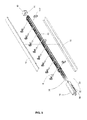
FIG. 5 is an exploded isometric view of the apparatus ofFIG. 1 . -
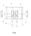
FIG. 6 is an exploded isometric view a user end of the apparatus ofFIG. 1 . -
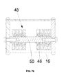
FIG. 7a is an exploded isometric view a tail end of the apparatus ofFIG. 1 . -
FIG. 7b is a cross-sectional end view of a tail end of the apparatus ofFIG. 1 . -
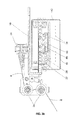
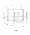
FIG. 8a is a cross-sectional end view of brake systems of the apparatus ofFIG. 1 , with the brake systems not engaged. -
FIG. 8b is a cross-sectional end view of brake systems of the apparatus ofFIG. 1 , with one of the brake systems engaged. -
FIG. 8c is a detailed side view of a brake system member of the apparatus ofFIG. 1 . -
FIG. 9 is a cross-sectional end view of an alternative brake system of the apparatus ofFIG. 1 . -
FIG. 10 is an exploded isometric view of an alternative brake system of the apparatus ofFIG. 1 . -
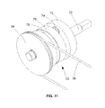
FIG. 11 is an isometric view of the brake system ofFIG. 10 . -
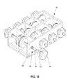
FIG. 12 is an isometric view of another alternative brake system of the apparatus ofFIG. 1 . -
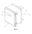
FIG. 13 is an isometric view a control panel of the apparatus ofFIG. 1 . -
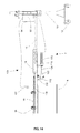
FIG. 14 is a side view of the apparatus ofFIG. 1 showing a substrate tracking and adjustment system. -
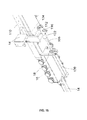
FIG. 15 is a detailed isometric view of the substrate tracking and adjustment system ofFIG. 14 . -
FIG. 16 is detailed orthogonal views of the guide rollers and a guide roller bracket of the substrate tracking and adjustment system ofFIG. 14 . -
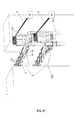
FIG. 17 is an isometric view of the apparatus ofFIG. 1 and a second, similar apparatus both installed in a substrate processing machine and dispensing strip materials onto and between a pair moving substrates. - Disclosed herein is a compact, light weight, and easily floor-moveable apparatus for the dispensing of strip materials onto a moving substrate in a substrate processing machine. The apparatus includes at least one strip material dispensing guide arm that may be independently adjustable transversely of the direction of movement of the substrate.
- The strip materials may be a ribbon material, such as tape, string and yarn, various web materials and various widths of material, particularly tapes that include an adhesive such as a hot melt adhesive, a hot melt pressure sensitive adhesive, a hot melt remoistenable adhesive, a water dispersible hot melt adhesive, a biodegradable hot melt adhesive or a repulpable hot melt adhesive, or heat activatable adhesives.
- The substrate may be a film, non-woven web, paper product, paper board, carton blank, box board, corrugated board or other sheet material or web material, all of various widths.
- The substrate processing machine may be a wet end, a dry end, or both a wet end and a dry end of a corrugation machine, a lamination machine, a carton press, a fiber reinforcement application machine, or other similar machines that processes a moving substrate. In some embodiments, the substrate processing machine can process more than one substrate at the same time, for example, one above the other, and can combine more than one substrate into a single substrate during the processing.
- According to one embodiment, changing the position of any one or more of the dispensing guide arms is accomplished by turning a series of crankshafts located at a head end of the apparatus. As the guide arms are moved, a control box precisely displays the position of each of the guide arms. This combination of moving the guide arms from the head end of the apparatus and the precise guide arm position readout enables apparatus setup and fine calibration without removing the apparatus from the substrate processing machine.
- Change in the position of the strip materials is dictated by the desired position of the strip material on the substrate and the later manufacturing of the substrate. Depending on the strength of the strip material, the same will be a suitable transverse reinforcement of the substrate or serve as a tear strip affording ease in opening the container to be formed from the substrate.
- As illustrated in
FIGS. 1 and2 , the apparatus, generally designated 2, is adapted to be positioned in various locations within asubstrate processing machine 4.FIG. 1 shows one possible location. Anapparatus 200, corresponding to theapparatus 2, can additionally be positioned in thesubstrate processing machine 4, for example above or below theapparatus 2, as shown inFIGS 2 and17 . Theapparatus 200 can be positioned on the opposite side of the substrate 6 to simultaneously applystrip materials 8 to the other side of the substrate 6. In other embodiments, theapparatus 200 can be positioned to apply strip materials to a second substrate. Theapparatus 200 can be used, for example, when strip materials are to be applied between different layers of a laminated substrate, such as in the manufacturing of "double wall" or "triple wall" corrugated board, and/or when strip materials are to be applied both between layers of a substrate and on an outer surface of the same substrate. Since theapparatus 2 is similar to theapparatus 200, only theapparatus 2 is described further. - In some embodiments, two or more upright support towers 10 can hold the
apparatus 2 in a generally horizontal position at a desired height above the ground. Each of these upright support towers 10 can be mounted onwheels 12 for increased mobility. Theapparatus 2 and towers 10 can be wheeled in and out of thesubstrate processing machine 4. In one embodiment, after being wheeled into themachine 4, a portion of theapparatus 2, e.g. aguide track 110, can be fixed to and supported by thesubstrate processing machine 4, and one or more of the upright support towers can then be removed. In another embodiment, the upright support towers 10 can hold theapparatus 2 within thesubstrate processing machine 4 during operation and theapparatus 2 is not attached to themachine 4. - An
extension member 14 can also be included to connect theapparatus 2 to anupright support tower 10 such that the tower can be located farther away from the laminating machine. The length of theextension member 14 can be adjustable, and in one embodiment, theextension member 14 has a hollow cross section. - The
apparatus 2 includes anelongated frame 16. Theframe 16 can be rectangular in cross section and can be constructed of aluminum. In certain embodiments, theframe 16 has a cross-sectional width of about 5.0 to 7.0 inches, and a cross-section height of about 4.25 inches. Theframe 16 supports and encloses many components of theapparatus 2, shielding them from starch and other contaminants. - The
frame 16 supports one ormore guide arms 18 that can be mounted in a series along the length of theframe 16. As shown inFIGS. 3a and3b , theframe 16 can also include aguide rail 20 fixed to theframe 16. Eachguide arm 18 can include a component for coupling theguide ann 18 to theguide rail 20, for example a low friction sliding or rolling device, and in particular alinear bearing 22, which mates to theguide rail 20. Eachguide arm 18 can have full range of theguide rail 20. As shown inFIG. 1 . theframe 16 andguide rail 20 can extend transversally beyond the edges of the substrate 6 such that theguide arms 16 can be positioned beyond the edges of the substrate 6. As shown inFIG. 4 , theguide arms 18 includepulleys 24 for receivingstrip materials 8 that can be fed to theguide arms 18 transversely of the substrate from aremote supply 26 and then dispensed onto the substrate 6 for attachment and lamination thereto. - In certain embodiments, the
frame 16 with mountedguide arms 18 andpulleys 24 can have a total cross-sectional width of about 12.1 inches and a total cross-sectional height of about 6.6 inches. - As shown in
FIGS. 1 ,2 , and5 , a guide arm moving and holdingassembly 30 can be located at an end of theframe 16 generally separate from the portion of the frame where theguide arms 18 are mounted. As shown inFIG. 6 , the guide arm moving and holdingassembly 30 can include at least one, and preferably a series of series of crank shaft(s) 32, head pulley(s) 34, cable(s) 36, and brake system(s) 38. - In one embodiment, a series of crank
shafts 32 arc rotably supported by thesides 42 of theframe 16 along parallel, horizontal axes. Pairs of shafts can be supported by theframe 16, side by side along the same axis. In this format, a center member 40 of theframe 16 is vertically disposed between the two crankshafts 32 and supports the inner ends of both crankshafts 32 such that they can rotate independently. The outer ends of thecrank shafts 32 pass throughopposite side walls 42 of theframe 16 and are connected to drivemechanisms 44. Thedrive mechanisms 44 can be manual cranks or automated devices, such as electric motors or actuators. - A
head pulley 34 is fixed to each crankshaft 32 within theframe 16 such that thehead pulley 34 rotates with thecrank shaft 32. Eachcable 36 is secured to acorresponding guide arm 18 and makes a closed loop wrapping around ahead pulley 32 and atail pulley 46. Thetail pulley assembly 48, shown inFIGS. 7a and7b , is supported by theframe side walls 42 at the opposite end as the head pulleys 34. Thetail pulley assembly 48 includes a series of independently rotable idler pulleys 46 that can be mounted on acommon shaft 50 that is parallel to the crankshafts 32. - The cable-pulley system is a friction-drive system that relies on the tension of the
cable 36 strained around thehead pulley 34 to move and hold theguide arms 18 in their desired positions. Tension can be necessary to prevent thecable 36 from slipping on thepulley 34 when theguide arms 18 exert a force on thecable 36, such as from a residual tension of thestrip material 8 or an occasional jerk resulting from the splicing of two ends of runningstrip material 8. Tension can also be necessary to prevent thecable 36 from slipping on thepulley 34 when thecrank shaft 32 is turned to move aguide arm 18 to a desired position. The frictional resistance generated can be the product of the tension force multiplied by the coefficient of static friction between the cable and pulley materials. The functional resistance of thecable 36 on thepulley 34 and the angle subtending the arc of contact between thepulley 34 and tension element are the primary factors that affect the design and performance of the cable-pulley friction-drive systems. - An alternative to the cable-pulley friction-drive system, which relies on the tension of a cable strained around a pulley to move and hold guide arms in their desired positions, is a chain-sprocket direct-drive system, which relies on intimately interlocking contact between chain links and sprocket teeth to move and hold guide arms to desired positions. In such a direct-drive system, tension is not required to prevent the chain from slipping on the sprocket when moving a guide arm to the desired position or when guide arms exert a force on the chain. Other direct-drive systems include gear and threaded rod drives that also rely on the intimate interlocking contact between drive elements to provide the desired motive force.
- As shown in
FIG. 6 , a series ofbrake systems 38 can be included to fix theguide arms 18 in desired positions along theguide rail 20. In one embodiment, eachbrake system 38 includes a horseshoe-shapedmember 64, shown inFIG. 8a - 8c , that wraps around a portion of acorresponding head pulley 34. This member moves into contact with and frictionally retards the rotation of thehead pulley 34 when an attachedbrake lever 66 is actuated. One end of the horseshoe-shapedmember 64 can be fixed to theframe 16 while the other end protrudes through theframe 16 and couples to thebrake lever 66. Thebrake lever 66 can include a cam portion and can be coupled to theframe 16 such that thebrake lever 66 can be actuated, as shown inFIG. 8b , and thereby urge the horseshoe shapedmember 64 into contact with thehead pulley 34. Thebrake system 38 can be arranged to hold thehead pulley 34 in place when thelever 66 is actuated and keep thehead pulley 34 stationary without maintained pressure on thelever 66. - In another embodiment, shown in
FIG. 9 , thebrake systems 38 can include a similar horseshoe-shapedfriction member 64 that is biased, such as by aspring 68, to be continually pressed against ahead pulley 34. The constant static friction force generated by thebiased friction member 64 and thehead pulley 34 can be sufficient to keep theguide arm 18 stationary against vibrations and forces applied to theguide arm 18 during operation. The constant friction force can be weak enough, however, to be overcome by manual or mechanized turning of thecrank shaft 32. In this embodiment, thebrake systems 38 do not need to be applied and disengaged or otherwise adjusted during operation. - In another embodiment, shown in
FIGS. 10-11 , thebrake systems 38 can include aclutch brake system 70 mounted on each crankshaft 32. Theclutch brake system 70 can include a disk-shapedback plate 72 mounted rotably on thecrank shaft 32. One ormore springs 74 can be fixed at one end to theback plate 72, and fixed at the other end to aclutch disk 76. Theclutch disk 76 is also mounted rotably on thecrank shaft 32, between theback plate 72 and thehead pulley 34. The surface of theclutch disk 76 facing thehead pulley 34 is lined with afriction pad 78 that can be pressed against the side of thehead pulley 34 by thesprings 74, as shown inFIG. 10 . When theback plate 72 is fixed relative to theframe 16, the friction from thefriction pad 78 against thehead pulley 34 can keep thehead pulley 34 from turning until theback plate 72 is released from theframe 16 by a lever or other means. - In yet another embodiment, shown in
FIG. 12 , thebrake systems 38 can include a shaft brake 80. Each crankshaft 32 can be threaded at a location 82 near aside wall 42 of theframe 16. A nut 84 can be threaded onto thecrank shaft 32. To prevent thecrank shaft 32 from turning, the nut 84 can be rotated such that the nut 84 moves along thecrank shaft 32 and presses against a surface of theframe 16, such as theside wall 42. A drive mechanism 44 (not shown inFIG. 12 ) can be coupled to the end portion of thecrank shaft 32 shown inFIG. 12 as having a square cross-section. - Each of these brake system embodiments can create a friction-brake system that relies exclusively or primarily on the friction force between a surface of a friction member, such as the horseshoe-shaped
member 64, thebrake pad 78, or the brake nut 84, and a surface of a moving component of the drive system, such as ahead pulley 34 or acrank shaft 32, to keep theguide arms 18 8 in their desired positions. In each embodiment, the friction force generated to restrict the motion of arm guide arm is a product of a normal force exerted upon the friction member multiplied by the coefficient of friction between the friction member and the drive system component. The normal force can be supplied by manual pressure transferred to the friction member through a suitable device, such as a lever or spring system. - The
apparatus 2 can include a system for determining the position of theguide arms 18 transversely of the substrate direction of movement or the machine direction of the substrate 6. In such a system, thelinear bearing 22 of eachguide arm 18 can have amagnet 88 mounted to it that cooperates with a transducer 90, as shown inFIG. 3 . Theframe 16 supports the transducer 90 to afford a reading as to the position of theguide arms 18 with respect to theframe 16. The transducer 90 can be connected to acontrol panel 92, shown inFIG. 13 , having adisplay 94 providing a numeric digital readout giving the location along theframe 16 of theguide arms 18. Thecontrol panel 92 can havebuttons 96 for user input, such as to select whicharm 18 to monitor. Thecontrol panel 92 can be remotely located, and is mounted on anupright support tower 10 in one embodiment. Acable 98 connecting the transducer 90 to thecontrol panel 92 can be routed through theframe 16 and through thehollow extension member 14, thereby keeping thecable 98 safe from harm. - The
magnets 88 cooperate with the transducer 90 to afford a signal in response to a current pulse sent from thecontrol panel 92 along the transducer 90. The signal from eacharm 18 can be discerned by the electronics in thecontrol panel 92 to calculate the distance anyparticular guide arm 18 is from the predetermined "0" and the numeric value can then be displayed on thedisplay 94. - The transducer 90 and
control panel 92 operation allows an operator to view the precise location of anyguide arm 18. The control circuitry can trigger the transducer 90 to send a current pulse down a wire held inside the transducer 90. The current in the wire can then create an electric field about the wire. When the current flowing down the wire reaches theguide arm 18 in question, the electrical field of the wire interacts with the magnetic field of themagnet 88 on theguide arm 18. This interaction creates a torque in the wire producing a signal by thearm 18. The electronics of the transducer 90 calculate how long in time it was from when the current pulse was sent down the wire to when the reaction signal in the wire is sensed. From this information, the position of theguide arm 18 is discerned and the distance is calculated from the present "0" and a numeric value is displayed on the display of thecontrol panel 92. The electronics can be designed to discern whichmagnet 88 from which to read the electric field-magnet field location signal. The operator then has a precise position reading and can adjust thearms 18 as necessary by rotating appropriate crankshafts 32. - As shown in
FIG. 14 , a substrate tracking andadjustment system 100 including asubstrate sensor 102,control panel 92, andactuator 106 can be used to track the position of the substrate 6 as it moves side to side from the normal substrate path or position. The substrate tracking andadjustment system 100 is used to maintain the position of aframe 16 in relation to the substrate 6. Thesubstrate tracking sensor 102 can be placed somewhere on thesubstrate processing machine 4, such as upstream from theapparatus 2 as shown inFIG. 1 , or thetracking sensor 102 can be affixed to theapparatus 2, preferably at a stationary location. The substrate sensor orsensors 102 can include laser, camera, proximity, pneumatic, ultrasonic, photo, optical, or other suitable sensing means. - As shown in
FIG. 15 , amovable end 120 of alinear actuator 106 can be secured to theframe 16 via an actuator-frame bracket 118 and afixed end 122 of theactuator 106 can be secured to aguide track 110 via an actuator-track bracket 116. Theactuator 106 can be driven hydraulically, pneumatically, magnetically, by a motor, or by other suitable driving means. Theframe 16 can be mounted to theguide track 110 on two or more pairs ofguide rollers 112, shown in detail inFIG. 16 , so as to allow theframe 16 to freely move along the length of the guide track I 10 if theframe 16 were not secured to thelinear actuator 106. The pairs ofguide rollers 112 2 can be fixed to theframe side wall 42 viaguide roller brackets 124. Theframe side wall 42 can be provided with multiple mounting locations along its length such that theguide roller brackets 124 can be attached at varying distance apart from each other. Theactuator 106 can move theframe 16 on theguide track 110 by extending or contracting. Theguide track 110 can be attached to a stationary object, such as a frame of thesubstrate processing machine 4, via a track bracket 114. - In one embodiment, the
apparatus 2, including between one to eight guidearms 18, friction drive systems, horseshoe-typefriction brake systems 38,linear bearings 22 andmagnets 88, plus the transducer 90, guiderollers 112 and track brackets 114, and other necessary components, but not including theextension member 14, upright support towers 10, orguide track 110, can weigh 130 lbs to 165 lbs, depending on the number of guide arms and related systems installed. - In some embodiments, the installation of the
apparatus 2 with the substrate tracking andadjustment system 100 into the operational position within asubstrate processing machine 4 can be accomplished by first installing theguide track 110 and the actuator-track bracket 116 onto a stationary structural component of thesubstrate processing machine 4 via one or more tack brackets 114. Next, with theguide rollers 112 andliner actuator 106 pre-mounted on theframe 16, theapparatus 2 can be wheeled on two upright support towers 10, as shown inFIG. 2 , into a position where the a first pair ofguide rollers 112 are adjacent to an end of theguide track 110. Then, the first pair ofguide rollers 112 are installed onto theguide track 110 by allowing end of theguide track 110 to move between the first pair ofguide rollers 112. Next, one of the upright support towers 10 are removed and theguide track 110 supports the mounted end of theapparatus 2. Next, theapparatus 2 is further rolled into themachine 4 until the second set ofguide track rollers 112 mount onto the end of theguide track 110. Finally, thefixed end 122 of thelinear actuator 106 is attached to theactuator track bracket 116. - As the substrate 6 passes through the
substrate processing machine 4 in the same direction as thestrip material 8 application, thesubstrate sensor 102 can detect the transversal position of the substrate 6. Thesubstrate sensor 102 can then transmit the substrate position information to a controller 104. Thecontrol panel 92 can then compare the substrate position to the frame's preset position. If the substrate position is not aligned to the preset frame position, thecontrol panel 92 can send a command signal to theactuator 106 to move theframe 16 to be aligned with the substrate position. As theframe 16 is moved along theguide track 110, each of theguide arms 18 mounted on theframe 16 are simultaneously moved the same distance. This sensing, comparing, and adjusting loop can be done continuously to maintain theframe 16 and guidearms 18 in the desired position in relation to the substrate 6. - Once the apparatus is fully installed into the substrate processing machine, operation can begin. First the
strip materials 8 are taken from a bulk source and threaded through or around various strip guides 130 attached to theupright support tower 10, as shown inFIG. 17 . Next, the strip materials are threaded around guide arm pulleys 24 and attached to the substrate 6. Then, as the substrate moves it pulls the strip materials from the bulk source, through theguides 130 andpulleys 24 and onto the moving substrate. The strip materials can be attached to the substrate while the substrate is moving or while stationary. Furthermore, the guide arms need not be in desired transversal positions along the frame prior to attaching the strip materials to the substrate or prior to the substrate commencing movement through the machine. The guide arms can be adjusted while the substrate is moving and the strip materials are being dispensed. - To adjust the positioning of each strip of material onto the substrate, the corresponding
brake systems 38 are first loosened, if needed, and then the user turns thecorresponding drive mechanisms 44, which can be hand cranks, which in turn rotate crankshafts 32 and attached drive pulleys 34. The rotating drive pulleys 34, in coordination with the tail pulleys 46, movescables 36 about a loop. When thecables 36 move, they pull the connectedguide arms 18, which slide along the frame via theguide rail 20 onbearings 22. - To measure each new position, the
magnets 88 of each guide arm interact with the transducer 90 and send a signal to thecontrol panel 92 signifying the location of eachguide arm 18 in relation to a predetermined "0" location along the frame. The user can then interface with thebuttons 96 anddisplay 94 to select and read the location of each guide arm. If the guide arms are not in the desired positions, the user can then repeat these steps to adjust the guide arm positions to be more precise. - Once all the
guide arms 16 arc similarly moved to the desired new positions, thebrake systems 38 can optionally be applied to hold them in place. The user can also manually hold thedrive mechanisms 44 to hold theguide arms 16 in place. Thebrake systems 38 can be applied by various methods as described above, such as actuating levers or turning nuts. In the embodiment shown inFIG. 8b , thebrake lever 66 can be rotated towards theframe side wall 42, thereby employing a cam at the base of thelever 66 to pull the attachedhorseshoe member 64 downward and into frictional contact with thehead pulley 34. With or without the brake systems applied, typically with the brake systems applied, the strip material application process can commence. - To be more precise during the application process, the substrate tracking and adjustment system can optionally be used to automatically make transversal adjustments to all the guide arms in unison in reaction to side-to-side changes in the position of the moving substrate.
- When another guide arm position change is desired, these steps can repeated to re-adjust the guide arms, for example when there is an order change to manufacture a different product. All these steps can be done without removing the apparatus from the substrate processing machine or stopping the movement of the substrate.
- In view of the many possible embodiments to which the principles of the disclosed devices and methods may be applied, it should be recognized that the illustrated embodiments are only preferred examples and should not be taken as limiting the scope of the invention as defined by the appended claims.
Claims (24)
- An apparatus for dispensing strip materials (8) onto at least one moving substrate (6), comprising:a frame (16) extending transversally of the substrate path;at least two guide arms (18), each having a supporting means to movably attach the guide arm to the frame and a dispensing means for dispensing strip materials; anda guide arm positioning system, characterised in that the guide arm positioning system comprises:i) at least two crank shafts (32) coupled to a first end of the frame (16), such that each crank shaft can rotate about an independent axis per crank shaft; andii) at least two friction drive means, one friction drive means being coupled to each crank shaft (32) and a corresponding guide arm (18), each friction drive means depending on frictional contact between two surfaces to transfer rotational movement of a crank shaft to linear motion of a guide arm;wherein each guide arm (18) is independently movable along the frame (16) by rotation of the corresponding crank shaft (32).
- The apparatus of claim 1, wherein each friction drive means comprises:a drive pulley (34), the drive pulley being fixed to one crank shaft (32),a tail pulley (46) rotably coupled to a second, opposite end of the frame (16), a cable (36), the cable extending around the drive pulley and the tail pulley and is attached to the guide arm (18) therebetween which guide arm corresponds to the crank shaft (32).
- The apparatus of claim 1, wherein the guide arm positioning system further comprises at least two friction braking means (38), one friction breaking means coupled to each friction drive means and supported by the frame (16) and configured to restrict movement of the corresponding guide arm (18).
- The apparatus of claim 3, wherein each friction braking means (38) comprises a friction surface, the friction surface configured to press against a component of the corresponding friction drive means and restrict motion of the corresponding guide arm (18).
- The apparatus of claim 4, wherein a horseshoe-shaped member (64) comprises the friction surface.
- The apparatus of claim 4, wherein a clutch-like, disk-shaped member (76) comprises the friction surface.
- The apparatus of claim 4, wherein a nut-like, internally threaded member (84) comprises the friction surface.
- The apparatus of claim 1, wherein each friction drive means is substantially physically enclosed.
- The apparatus of claim 1, wherein a first guide arm (18) is disposed above a first moving substrate (6) and a second guide arm is disposed below the first moving substrate.
- The apparatus of claim 9, wherein one guide arm (18) can dispense strip materials onto the first moving substrate (6) and another guide arm can dispense strip materials onto a second moving substrate located above or below the first moving substrate.
- The apparatus of claim 1, further comprising a guide arm position feedback system for automatically determining the transversal position of each guide arm (18) in relation to a predetermined position and displaying the transversal positions on a display device.
- The apparatus of claim 11, wherein the guide arm position feedback means comprises at least one magnet (88) and at least one transducer (90).
- The apparatus of claim 1, further comprising a substrate position sensor (102) or determining the transversal position of the substrate (6).
- The apparatus of claim 13, further comprising an actuator (106) that can adjust the transversal location of the frame (16) relative to the substrate (6) in response to a signal from the substrate sensor means, thereby adjusting all of the mounted guide arms (18) in unison.
- The apparatus of claim 14, wherein the determining of the location of the substrate (6) and the adjusting of the position of the frame (18) relative to the substrate can be repeatedly performed to maintain the frame (16) in a desired position in relation to the substrate.
- The apparatus of claim 1, wherein the each of the at least two crank shafts (32) can rotate about an axis that is substantially perpendicular to the direction of movement of the corresponding guide arm (18).
- The apparatus of claim 1, wherein the at least two crank shafts (32) are rotatable about separate and substantially parallel axes.
- The apparatus of claim 17, wherein two of the crank shafts (32) can rotate about the same axis independently.
- The apparatus of claim 18, wherein there are two or more sets of two crank shafts (32) that can rotate about the same axis independently, each set rotating about separate and substantially parallel axes.
- The apparatus of claim 17, wherein the drive pulleys (34) fixed to the crank shafts (32) can rotate in separate and substantially parallel planes, the planes being perpendicular to the crank shaft rotation axes.
- The apparatus of claim 1, wherein each of the crank shafts (32) can be rotated by a motorized device coupled to the crank shaft outside of the frame.
- A process for preparing to dispense strip materials (8) onto a moving substrates (6), comprising:i) rotating at least two crank shafts (32) coupled to a first end of a frame (16) such that each crank shaft can rotate about an independent axis per crank shaft, the frame extending transversally of the substrate path, each rotating crank shaft thereby actuating a friction drive means, the friction drive means being coupled to the crank shaft and a corresponding guide arm (18), the friction drive means depending on frictional contact between two surfaces to transfer rotational movement of the crank shaft to linear motion of the corresponding guide arm, the friction drive means thereby moving the corresponding guide arm to a desired position along the frame, the corresponding guide arm having a supporting means to movably couple the guide arm to the frame and a dispensing means for dispensing strip materials onto the substrate.
- The process of claim 22, further comprising:ii) using a guide arm position feedback means to automatically determine the transversal position of each guide arm (18) in relation to a predetermined position and display the positions on a display device.
- The process of claim 23, further comprising:iii) repeating i and ii until the display device displays the desired positions of the guide arms.
Priority Applications (1)
| Application Number | Priority Date | Filing Date | Title |
|---|---|---|---|
| PL10773458T PL2490969T3 (en) | 2009-10-19 | 2010-10-18 | Strip material dispensing device |
Applications Claiming Priority (2)
| Application Number | Priority Date | Filing Date | Title |
|---|---|---|---|
| US12/581,611 US8640982B2 (en) | 2009-10-19 | 2009-10-19 | Strip material dispensing device |
| PCT/US2010/053069 WO2011049877A1 (en) | 2009-10-19 | 2010-10-18 | Strip material dispensing device |
Publications (2)
| Publication Number | Publication Date |
|---|---|
| EP2490969A1 EP2490969A1 (en) | 2012-08-29 |
| EP2490969B1 true EP2490969B1 (en) | 2014-08-13 |
Family
ID=43413725
Family Applications (1)
| Application Number | Title | Priority Date | Filing Date |
|---|---|---|---|
| EP10773458.4A Active EP2490969B1 (en) | 2009-10-19 | 2010-10-18 | Strip material dispensing device |
Country Status (10)
| Country | Link |
|---|---|
| US (2) | US8640982B2 (en) |
| EP (1) | EP2490969B1 (en) |
| CN (1) | CN102686496B (en) |
| AR (1) | AR078699A1 (en) |
| BR (1) | BR112012009199A2 (en) |
| CA (1) | CA2786135C (en) |
| ES (1) | ES2523600T3 (en) |
| MX (1) | MX2012003623A (en) |
| PL (1) | PL2490969T3 (en) |
| WO (1) | WO2011049877A1 (en) |
Families Citing this family (6)
| Publication number | Priority date | Publication date | Assignee | Title |
|---|---|---|---|---|
| US8640982B2 (en) * | 2009-10-19 | 2014-02-04 | Adalis Corp. | Strip material dispensing device |
| US9669588B2 (en) | 2014-09-04 | 2017-06-06 | H.B. Fuller Company | Devices and methods for starting strip material in a substrate processing machine |
| US9764512B2 (en) | 2014-09-04 | 2017-09-19 | H.B. Fuller Company | Devices and methods for starting strip material in a substrate processing machine |
| CN107187906B (en) * | 2016-03-15 | 2019-05-28 | 柯尼卡美能达株式会社 | Paper transport device and image forming apparatus |
| CN107059241B (en) * | 2016-03-15 | 2019-01-08 | 陈广佑 | The working method of the macromolecular fibre traction device of polyamide skeleton |
| CN108313790A (en) * | 2018-02-05 | 2018-07-24 | 陈建辉 | The production system of roll paper |
Family Cites Families (27)
| Publication number | Priority date | Publication date | Assignee | Title |
|---|---|---|---|---|
| US199333A (en) * | 1878-01-15 | Improvement in cuspadores | ||
| US139470A (en) * | 1873-06-03 | Improvement in apparatus for cooling rooms | ||
| US56894A (en) * | 1866-08-07 | Improvement in bag-fasteners | ||
| US74817A (en) * | 1868-02-25 | Kingston goddarp | ||
| US2911835A (en) * | 1956-07-05 | 1959-11-10 | Deering Milliken Res Corp | Traversing arrangement |
| US3093344A (en) * | 1960-01-21 | 1963-06-11 | Monsanto Chemicals | Traversing device |
| US3177751A (en) * | 1962-08-06 | 1965-04-13 | Corrugating Technicians Inc | Edge aligning apparatus |
| US3245594A (en) * | 1964-03-26 | 1966-04-12 | Honeywell Inc | Mechanical apparatus |
| US4120740A (en) * | 1974-09-13 | 1978-10-17 | Ronald Wade Morgan | Tape applicator for drapery tabler |
| US4452837A (en) | 1979-06-11 | 1984-06-05 | H. B. Fuller Company | Web reinforced with string-type adhesive and method of manufacturing same |
| US4481054A (en) | 1981-11-19 | 1984-11-06 | H. B. Fuller Company | Method of forming reinforcing network |
| SE455698B (en) | 1986-12-01 | 1988-08-01 | Foerenade Well Ab | ADJUSTABLE BRAKE APPLICATION DEVICE WITH ADJUSTABLE GRADED ADJUSTMENT BELT |
| DE4424197C2 (en) | 1994-07-08 | 1996-07-11 | Gueldenring Maschinenbau Gmbh | Rip cutter |
| US5507432A (en) | 1994-10-25 | 1996-04-16 | Industrial Adhesives, Inc. | System for separating corrugated fiberboard |
| IT1282743B1 (en) * | 1996-05-24 | 1998-03-31 | Menegatto Srl | PERFECTED REWINDING MACHINE |
| GB2318084B (en) * | 1996-10-14 | 1998-09-09 | Tecksom International Limited | Laminating apparatus |
| US5775629A (en) | 1996-10-31 | 1998-07-07 | Industrial Adhesives, Inc. | Non-twisting transfer tail system |
| US5759339A (en) | 1996-12-12 | 1998-06-02 | Linear Products Inc | Ribbon dispensing guide arm and positioning device |
| US7368159B2 (en) | 2000-09-07 | 2008-05-06 | International Paper Company | Reinforcing strips for corrugated paperboard and related method and apparatus for its manufacture |
| CA2485314A1 (en) | 2001-04-03 | 2002-10-03 | Martin Robitaille | Automatic guide arms apparatus and method |
| CA2443772C (en) | 2001-04-12 | 2008-03-25 | H.B. Fuller Licensing & Financing, Inc. | Method and system for positioning guide arms in a strip fabrication assembly |
| US20030056894A1 (en) | 2001-09-25 | 2003-03-27 | John Getz | Applicator for adhesively-impregnated tape |
| US20050199333A1 (en) | 2001-09-25 | 2005-09-15 | Industrial Adhesives, Inc. | Tail for attaching the trailing edge of one roll of tape to the leading edge of another roll of tape and method of using same |
| US6981537B2 (en) | 2001-09-25 | 2006-01-03 | Industrial Adhesives, Inc. | Tail for attaching the trailing edge of one roll of tape to the leading edge of another roll of tape and method of using same |
| US6596111B2 (en) | 2001-09-25 | 2003-07-22 | Industrial Adhesives, Inc. | Tail for attaching the trailing edge of one roll of tape to the leading edge of another roll of tape and method of using same |
| US7681829B2 (en) | 2005-10-03 | 2010-03-23 | Gilles Cyr | Non-twist tail for joining tape ends |
| US8640982B2 (en) * | 2009-10-19 | 2014-02-04 | Adalis Corp. | Strip material dispensing device |
-
2009
- 2009-10-19 US US12/581,611 patent/US8640982B2/en active Active
-
2010
- 2010-10-18 MX MX2012003623A patent/MX2012003623A/en active IP Right Grant
- 2010-10-18 EP EP10773458.4A patent/EP2490969B1/en active Active
- 2010-10-18 CA CA2786135A patent/CA2786135C/en active Active
- 2010-10-18 ES ES10773458.4T patent/ES2523600T3/en active Active
- 2010-10-18 WO PCT/US2010/053069 patent/WO2011049877A1/en not_active Ceased
- 2010-10-18 CN CN201080047264.2A patent/CN102686496B/en not_active Expired - Fee Related
- 2010-10-18 PL PL10773458T patent/PL2490969T3/en unknown
- 2010-10-18 AR ARP100103795A patent/AR078699A1/en active IP Right Grant
- 2010-10-18 BR BR112012009199A patent/BR112012009199A2/en not_active Application Discontinuation
-
2014
- 2014-01-03 US US14/146,889 patent/US20140116849A1/en not_active Abandoned
Also Published As
| Publication number | Publication date |
|---|---|
| CA2786135A1 (en) | 2011-04-28 |
| ES2523600T3 (en) | 2014-11-27 |
| US8640982B2 (en) | 2014-02-04 |
| CN102686496A (en) | 2012-09-19 |
| US20110089214A1 (en) | 2011-04-21 |
| EP2490969A1 (en) | 2012-08-29 |
| CA2786135C (en) | 2015-08-11 |
| CN102686496B (en) | 2015-06-24 |
| MX2012003623A (en) | 2012-04-20 |
| BR112012009199A2 (en) | 2016-08-16 |
| US20140116849A1 (en) | 2014-05-01 |
| AR078699A1 (en) | 2011-11-30 |
| PL2490969T3 (en) | 2015-02-27 |
| WO2011049877A1 (en) | 2011-04-28 |
Similar Documents
| Publication | Publication Date | Title |
|---|---|---|
| US20140116849A1 (en) | Strip material dispensing device | |
| US4517436A (en) | Laser marker for articles of manufacture | |
| SK180198A3 (en) | Wrapping apparatus | |
| SK73399A3 (en) | Device and method for feeding film | |
| US11993411B2 (en) | Film dispenser for a wrapping apparatus and related methods | |
| EP0057523B1 (en) | Slitter-rewinder apparatus | |
| US5395209A (en) | Palletizer | |
| US8720333B2 (en) | Buffering and tension control system and method | |
| US5759339A (en) | Ribbon dispensing guide arm and positioning device | |
| CN105883459B (en) | Material collecting device, rewinding component and the method for collecting film | |
| US7222653B2 (en) | Automatic guide arms apparatus | |
| JPS61277559A (en) | Raw fabric converter | |
| JP3989006B2 (en) | Winding foil material support and drive module for a machine for processing the winding foil material | |
| JP2001334574A (en) | Roll forming equipment system | |
| US11707928B2 (en) | Thermal transmission tubular marking | |
| JP2882750B2 (en) | Large paper bundle binding machine | |
| CN114229548A (en) | Automatic roll up membrane tightening means | |
| JPH0380707B2 (en) | ||
| CN1440006A (en) | Tension control experimental facility | |
| JP3579611B2 (en) | Label sticking device | |
| JP2897702B2 (en) | Method and device for attaching double-sided tape to PVC sheet | |
| JP2002087670A (en) | Tension device | |
| JPH0223019B2 (en) | ||
| JPH11105364A (en) | Printing machine | |
| WO2002083358A2 (en) | Positioning device for multiple transversely spaced operating units |
Legal Events
| Date | Code | Title | Description |
|---|---|---|---|
| PUAI | Public reference made under article 153(3) epc to a published international application that has entered the european phase |
Free format text: ORIGINAL CODE: 0009012 |
|
| 17P | Request for examination filed |
Effective date: 20120504 |
|
| AK | Designated contracting states |
Kind code of ref document: A1 Designated state(s): AL AT BE BG CH CY CZ DE DK EE ES FI FR GB GR HR HU IE IS IT LI LT LU LV MC MK MT NL NO PL PT RO RS SE SI SK SM TR |
|
| DAX | Request for extension of the european patent (deleted) | ||
| GRAP | Despatch of communication of intention to grant a patent |
Free format text: ORIGINAL CODE: EPIDOSNIGR1 |
|
| INTG | Intention to grant announced |
Effective date: 20140305 |
|
| GRAS | Grant fee paid |
Free format text: ORIGINAL CODE: EPIDOSNIGR3 |
|
| GRAA | (expected) grant |
Free format text: ORIGINAL CODE: 0009210 |
|
| AK | Designated contracting states |
Kind code of ref document: B1 Designated state(s): AL AT BE BG CH CY CZ DE DK EE ES FI FR GB GR HR HU IE IS IT LI LT LU LV MC MK MT NL NO PL PT RO RS SE SI SK SM TR |
|
| REG | Reference to a national code |
Ref country code: GB Ref legal event code: FG4D |
|
| REG | Reference to a national code |
Ref country code: AT Ref legal event code: REF Ref document number: 682078 Country of ref document: AT Kind code of ref document: T Effective date: 20140815 Ref country code: CH Ref legal event code: EP |
|
| REG | Reference to a national code |
Ref country code: IE Ref legal event code: FG4D |
|
| REG | Reference to a national code |
Ref country code: DE Ref legal event code: R096 Ref document number: 602010018267 Country of ref document: DE Effective date: 20140925 |
|
| REG | Reference to a national code |
Ref country code: CH Ref legal event code: NV Representative=s name: MAIWALD PATENTANWALTSGESELLSCHAFT (SCHWEIZ) MB, CH |
|
| REG | Reference to a national code |
Ref country code: ES Ref legal event code: FG2A Ref document number: 2523600 Country of ref document: ES Kind code of ref document: T3 Effective date: 20141127 |
|
| REG | Reference to a national code |
Ref country code: NL Ref legal event code: T3 |
|
| REG | Reference to a national code |
Ref country code: AT Ref legal event code: MK05 Ref document number: 682078 Country of ref document: AT Kind code of ref document: T Effective date: 20140813 |
|
| REG | Reference to a national code |
Ref country code: LT Ref legal event code: MG4D |
|
| PG25 | Lapsed in a contracting state [announced via postgrant information from national office to epo] |
Ref country code: NO Free format text: LAPSE BECAUSE OF FAILURE TO SUBMIT A TRANSLATION OF THE DESCRIPTION OR TO PAY THE FEE WITHIN THE PRESCRIBED TIME-LIMIT Effective date: 20141113 Ref country code: BG Free format text: LAPSE BECAUSE OF FAILURE TO SUBMIT A TRANSLATION OF THE DESCRIPTION OR TO PAY THE FEE WITHIN THE PRESCRIBED TIME-LIMIT Effective date: 20141113 Ref country code: SE Free format text: LAPSE BECAUSE OF FAILURE TO SUBMIT A TRANSLATION OF THE DESCRIPTION OR TO PAY THE FEE WITHIN THE PRESCRIBED TIME-LIMIT Effective date: 20140813 Ref country code: GR Free format text: LAPSE BECAUSE OF FAILURE TO SUBMIT A TRANSLATION OF THE DESCRIPTION OR TO PAY THE FEE WITHIN THE PRESCRIBED TIME-LIMIT Effective date: 20141114 Ref country code: LT Free format text: LAPSE BECAUSE OF FAILURE TO SUBMIT A TRANSLATION OF THE DESCRIPTION OR TO PAY THE FEE WITHIN THE PRESCRIBED TIME-LIMIT Effective date: 20140813 Ref country code: PT Free format text: LAPSE BECAUSE OF FAILURE TO SUBMIT A TRANSLATION OF THE DESCRIPTION OR TO PAY THE FEE WITHIN THE PRESCRIBED TIME-LIMIT Effective date: 20141215 |
|
| REG | Reference to a national code |
Ref country code: SK Ref legal event code: T3 Ref document number: E 17438 Country of ref document: SK |
|
| PG25 | Lapsed in a contracting state [announced via postgrant information from national office to epo] |
Ref country code: RS Free format text: LAPSE BECAUSE OF FAILURE TO SUBMIT A TRANSLATION OF THE DESCRIPTION OR TO PAY THE FEE WITHIN THE PRESCRIBED TIME-LIMIT Effective date: 20140813 Ref country code: AT Free format text: LAPSE BECAUSE OF FAILURE TO SUBMIT A TRANSLATION OF THE DESCRIPTION OR TO PAY THE FEE WITHIN THE PRESCRIBED TIME-LIMIT Effective date: 20140813 Ref country code: CY Free format text: LAPSE BECAUSE OF FAILURE TO SUBMIT A TRANSLATION OF THE DESCRIPTION OR TO PAY THE FEE WITHIN THE PRESCRIBED TIME-LIMIT Effective date: 20140813 Ref country code: LV Free format text: LAPSE BECAUSE OF FAILURE TO SUBMIT A TRANSLATION OF THE DESCRIPTION OR TO PAY THE FEE WITHIN THE PRESCRIBED TIME-LIMIT Effective date: 20140813 Ref country code: HR Free format text: LAPSE BECAUSE OF FAILURE TO SUBMIT A TRANSLATION OF THE DESCRIPTION OR TO PAY THE FEE WITHIN THE PRESCRIBED TIME-LIMIT Effective date: 20140813 Ref country code: IS Free format text: LAPSE BECAUSE OF FAILURE TO SUBMIT A TRANSLATION OF THE DESCRIPTION OR TO PAY THE FEE WITHIN THE PRESCRIBED TIME-LIMIT Effective date: 20141213 |
|
| REG | Reference to a national code |
Ref country code: PL Ref legal event code: T3 |
|
| PG25 | Lapsed in a contracting state [announced via postgrant information from national office to epo] |
Ref country code: DK Free format text: LAPSE BECAUSE OF FAILURE TO SUBMIT A TRANSLATION OF THE DESCRIPTION OR TO PAY THE FEE WITHIN THE PRESCRIBED TIME-LIMIT Effective date: 20140813 Ref country code: IT Free format text: LAPSE BECAUSE OF FAILURE TO SUBMIT A TRANSLATION OF THE DESCRIPTION OR TO PAY THE FEE WITHIN THE PRESCRIBED TIME-LIMIT Effective date: 20140813 Ref country code: RO Free format text: LAPSE BECAUSE OF FAILURE TO SUBMIT A TRANSLATION OF THE DESCRIPTION OR TO PAY THE FEE WITHIN THE PRESCRIBED TIME-LIMIT Effective date: 20140813 Ref country code: EE Free format text: LAPSE BECAUSE OF FAILURE TO SUBMIT A TRANSLATION OF THE DESCRIPTION OR TO PAY THE FEE WITHIN THE PRESCRIBED TIME-LIMIT Effective date: 20140813 |
|
| REG | Reference to a national code |
Ref country code: DE Ref legal event code: R097 Ref document number: 602010018267 Country of ref document: DE |
|
| PG25 | Lapsed in a contracting state [announced via postgrant information from national office to epo] |
Ref country code: LU Free format text: LAPSE BECAUSE OF FAILURE TO SUBMIT A TRANSLATION OF THE DESCRIPTION OR TO PAY THE FEE WITHIN THE PRESCRIBED TIME-LIMIT Effective date: 20141018 Ref country code: MC Free format text: LAPSE BECAUSE OF FAILURE TO SUBMIT A TRANSLATION OF THE DESCRIPTION OR TO PAY THE FEE WITHIN THE PRESCRIBED TIME-LIMIT Effective date: 20140813 |
|
| PLBE | No opposition filed within time limit |
Free format text: ORIGINAL CODE: 0009261 |
|
| STAA | Information on the status of an ep patent application or granted ep patent |
Free format text: STATUS: NO OPPOSITION FILED WITHIN TIME LIMIT |
|
| PG25 | Lapsed in a contracting state [announced via postgrant information from national office to epo] |
Ref country code: BE Free format text: LAPSE BECAUSE OF NON-PAYMENT OF DUE FEES Effective date: 20141031 |
|
| 26N | No opposition filed |
Effective date: 20150515 |
|
| REG | Reference to a national code |
Ref country code: IE Ref legal event code: MM4A |
|
| REG | Reference to a national code |
Ref country code: FR Ref legal event code: PLFP Year of fee payment: 6 |
|
| PG25 | Lapsed in a contracting state [announced via postgrant information from national office to epo] |
Ref country code: IE Free format text: LAPSE BECAUSE OF NON-PAYMENT OF DUE FEES Effective date: 20141018 |
|
| PG25 | Lapsed in a contracting state [announced via postgrant information from national office to epo] |
Ref country code: SI Free format text: LAPSE BECAUSE OF FAILURE TO SUBMIT A TRANSLATION OF THE DESCRIPTION OR TO PAY THE FEE WITHIN THE PRESCRIBED TIME-LIMIT Effective date: 20140813 |
|
| PG25 | Lapsed in a contracting state [announced via postgrant information from national office to epo] |
Ref country code: SM Free format text: LAPSE BECAUSE OF FAILURE TO SUBMIT A TRANSLATION OF THE DESCRIPTION OR TO PAY THE FEE WITHIN THE PRESCRIBED TIME-LIMIT Effective date: 20140813 |
|
| PG25 | Lapsed in a contracting state [announced via postgrant information from national office to epo] |
Ref country code: HU Free format text: LAPSE BECAUSE OF FAILURE TO SUBMIT A TRANSLATION OF THE DESCRIPTION OR TO PAY THE FEE WITHIN THE PRESCRIBED TIME-LIMIT; INVALID AB INITIO Effective date: 20101018 Ref country code: BE Free format text: LAPSE BECAUSE OF FAILURE TO SUBMIT A TRANSLATION OF THE DESCRIPTION OR TO PAY THE FEE WITHIN THE PRESCRIBED TIME-LIMIT Effective date: 20140813 Ref country code: MT Free format text: LAPSE BECAUSE OF FAILURE TO SUBMIT A TRANSLATION OF THE DESCRIPTION OR TO PAY THE FEE WITHIN THE PRESCRIBED TIME-LIMIT Effective date: 20140813 |
|
| REG | Reference to a national code |
Ref country code: CH Ref legal event code: PFA Owner name: ADALIS CORPORATION, US Free format text: FORMER OWNER: ADALIS CORPORATION, US |
|
| REG | Reference to a national code |
Ref country code: FR Ref legal event code: PLFP Year of fee payment: 7 |
|
| REG | Reference to a national code |
Ref country code: FR Ref legal event code: PLFP Year of fee payment: 8 |
|
| PG25 | Lapsed in a contracting state [announced via postgrant information from national office to epo] |
Ref country code: MK Free format text: LAPSE BECAUSE OF FAILURE TO SUBMIT A TRANSLATION OF THE DESCRIPTION OR TO PAY THE FEE WITHIN THE PRESCRIBED TIME-LIMIT Effective date: 20140813 |
|
| REG | Reference to a national code |
Ref country code: FR Ref legal event code: PLFP Year of fee payment: 9 |
|
| PG25 | Lapsed in a contracting state [announced via postgrant information from national office to epo] |
Ref country code: AL Free format text: LAPSE BECAUSE OF FAILURE TO SUBMIT A TRANSLATION OF THE DESCRIPTION OR TO PAY THE FEE WITHIN THE PRESCRIBED TIME-LIMIT Effective date: 20140813 |
|
| P01 | Opt-out of the competence of the unified patent court (upc) registered |
Effective date: 20230421 |
|
| PGFP | Annual fee paid to national office [announced via postgrant information from national office to epo] |
Ref country code: NL Payment date: 20241021 Year of fee payment: 15 |
|
| PGFP | Annual fee paid to national office [announced via postgrant information from national office to epo] |
Ref country code: CZ Payment date: 20241014 Year of fee payment: 15 |
|
| PGFP | Annual fee paid to national office [announced via postgrant information from national office to epo] |
Ref country code: SK Payment date: 20241016 Year of fee payment: 15 |
|
| PGFP | Annual fee paid to national office [announced via postgrant information from national office to epo] |
Ref country code: CH Payment date: 20241101 Year of fee payment: 15 |
|
| PGFP | Annual fee paid to national office [announced via postgrant information from national office to epo] |
Ref country code: TR Payment date: 20241011 Year of fee payment: 15 |
|
| PGFP | Annual fee paid to national office [announced via postgrant information from national office to epo] |
Ref country code: DE Payment date: 20251021 Year of fee payment: 16 |
|
| PGFP | Annual fee paid to national office [announced via postgrant information from national office to epo] |
Ref country code: GB Payment date: 20251022 Year of fee payment: 16 |
|
| PGFP | Annual fee paid to national office [announced via postgrant information from national office to epo] |
Ref country code: FI Payment date: 20251028 Year of fee payment: 16 |
|
| PGFP | Annual fee paid to national office [announced via postgrant information from national office to epo] |
Ref country code: FR Payment date: 20251030 Year of fee payment: 16 |
|
| PGFP | Annual fee paid to national office [announced via postgrant information from national office to epo] |
Ref country code: PL Payment date: 20251009 Year of fee payment: 16 |
|
| PGFP | Annual fee paid to national office [announced via postgrant information from national office to epo] |
Ref country code: ES Payment date: 20251210 Year of fee payment: 16 |