EP2490909B1 - Vorrichtung und verfahren zum drehmomentergänzung - Google Patents
Vorrichtung und verfahren zum drehmomentergänzung Download PDFInfo
- Publication number
- EP2490909B1 EP2490909B1 EP10775750.2A EP10775750A EP2490909B1 EP 2490909 B1 EP2490909 B1 EP 2490909B1 EP 10775750 A EP10775750 A EP 10775750A EP 2490909 B1 EP2490909 B1 EP 2490909B1
- Authority
- EP
- European Patent Office
- Prior art keywords
- flywheel
- torque
- vehicle
- energy
- supply
- Prior art date
- Legal status (The legal status is an assumption and is not a legal conclusion. Google has not performed a legal analysis and makes no representation as to the accuracy of the status listed.)
- Not-in-force
Links
Images


Classifications
-
- B—PERFORMING OPERATIONS; TRANSPORTING
- B60—VEHICLES IN GENERAL
- B60K—ARRANGEMENT OR MOUNTING OF PROPULSION UNITS OR OF TRANSMISSIONS IN VEHICLES; ARRANGEMENT OR MOUNTING OF PLURAL DIVERSE PRIME-MOVERS IN VEHICLES; AUXILIARY DRIVES FOR VEHICLES; INSTRUMENTATION OR DASHBOARDS FOR VEHICLES; ARRANGEMENTS IN CONNECTION WITH COOLING, AIR INTAKE, GAS EXHAUST OR FUEL SUPPLY OF PROPULSION UNITS IN VEHICLES
- B60K6/00—Arrangement or mounting of plural diverse prime-movers for mutual or common propulsion, e.g. hybrid propulsion systems comprising electric motors and internal combustion engines
- B60K6/08—Prime-movers comprising combustion engines and mechanical or fluid energy storing means
- B60K6/10—Prime-movers comprising combustion engines and mechanical or fluid energy storing means by means of a chargeable mechanical accumulator, e.g. flywheel
- B60K6/105—Prime-movers comprising combustion engines and mechanical or fluid energy storing means by means of a chargeable mechanical accumulator, e.g. flywheel the accumulator being a flywheel
-
- B—PERFORMING OPERATIONS; TRANSPORTING
- B60—VEHICLES IN GENERAL
- B60K—ARRANGEMENT OR MOUNTING OF PROPULSION UNITS OR OF TRANSMISSIONS IN VEHICLES; ARRANGEMENT OR MOUNTING OF PLURAL DIVERSE PRIME-MOVERS IN VEHICLES; AUXILIARY DRIVES FOR VEHICLES; INSTRUMENTATION OR DASHBOARDS FOR VEHICLES; ARRANGEMENTS IN CONNECTION WITH COOLING, AIR INTAKE, GAS EXHAUST OR FUEL SUPPLY OF PROPULSION UNITS IN VEHICLES
- B60K6/00—Arrangement or mounting of plural diverse prime-movers for mutual or common propulsion, e.g. hybrid propulsion systems comprising electric motors and internal combustion engines
- B60K6/20—Arrangement or mounting of plural diverse prime-movers for mutual or common propulsion, e.g. hybrid propulsion systems comprising electric motors and internal combustion engines the prime-movers consisting of electric motors and internal combustion engines, e.g. HEVs
- B60K6/22—Arrangement or mounting of plural diverse prime-movers for mutual or common propulsion, e.g. hybrid propulsion systems comprising electric motors and internal combustion engines the prime-movers consisting of electric motors and internal combustion engines, e.g. HEVs characterised by apparatus, components or means specially adapted for HEVs
- B60K6/30—Arrangement or mounting of plural diverse prime-movers for mutual or common propulsion, e.g. hybrid propulsion systems comprising electric motors and internal combustion engines the prime-movers consisting of electric motors and internal combustion engines, e.g. HEVs characterised by apparatus, components or means specially adapted for HEVs characterised by chargeable mechanical accumulators, e.g. flywheels
-
- B—PERFORMING OPERATIONS; TRANSPORTING
- B60—VEHICLES IN GENERAL
- B60K—ARRANGEMENT OR MOUNTING OF PROPULSION UNITS OR OF TRANSMISSIONS IN VEHICLES; ARRANGEMENT OR MOUNTING OF PLURAL DIVERSE PRIME-MOVERS IN VEHICLES; AUXILIARY DRIVES FOR VEHICLES; INSTRUMENTATION OR DASHBOARDS FOR VEHICLES; ARRANGEMENTS IN CONNECTION WITH COOLING, AIR INTAKE, GAS EXHAUST OR FUEL SUPPLY OF PROPULSION UNITS IN VEHICLES
- B60K6/00—Arrangement or mounting of plural diverse prime-movers for mutual or common propulsion, e.g. hybrid propulsion systems comprising electric motors and internal combustion engines
- B60K6/20—Arrangement or mounting of plural diverse prime-movers for mutual or common propulsion, e.g. hybrid propulsion systems comprising electric motors and internal combustion engines the prime-movers consisting of electric motors and internal combustion engines, e.g. HEVs
- B60K6/42—Arrangement or mounting of plural diverse prime-movers for mutual or common propulsion, e.g. hybrid propulsion systems comprising electric motors and internal combustion engines the prime-movers consisting of electric motors and internal combustion engines, e.g. HEVs characterised by the architecture of the hybrid electric vehicle
- B60K6/48—Parallel type
-
- B—PERFORMING OPERATIONS; TRANSPORTING
- B60—VEHICLES IN GENERAL
- B60W—CONJOINT CONTROL OF VEHICLE SUB-UNITS OF DIFFERENT TYPE OR DIFFERENT FUNCTION; CONTROL SYSTEMS SPECIALLY ADAPTED FOR HYBRID VEHICLES; ROAD VEHICLE DRIVE CONTROL SYSTEMS FOR PURPOSES NOT RELATED TO THE CONTROL OF A PARTICULAR SUB-UNIT
- B60W10/00—Conjoint control of vehicle sub-units of different type or different function
- B60W10/10—Conjoint control of vehicle sub-units of different type or different function including control of change-speed gearings
- B60W10/11—Stepped gearings
-
- B—PERFORMING OPERATIONS; TRANSPORTING
- B60—VEHICLES IN GENERAL
- B60W—CONJOINT CONTROL OF VEHICLE SUB-UNITS OF DIFFERENT TYPE OR DIFFERENT FUNCTION; CONTROL SYSTEMS SPECIALLY ADAPTED FOR HYBRID VEHICLES; ROAD VEHICLE DRIVE CONTROL SYSTEMS FOR PURPOSES NOT RELATED TO THE CONTROL OF A PARTICULAR SUB-UNIT
- B60W30/00—Purposes of road vehicle drive control systems not related to the control of a particular sub-unit, e.g. of systems using conjoint control of vehicle sub-units
- B60W30/18—Propelling the vehicle
- B60W30/19—Improvement of gear change, e.g. by synchronisation or smoothing gear shift
-
- B—PERFORMING OPERATIONS; TRANSPORTING
- B60—VEHICLES IN GENERAL
- B60W—CONJOINT CONTROL OF VEHICLE SUB-UNITS OF DIFFERENT TYPE OR DIFFERENT FUNCTION; CONTROL SYSTEMS SPECIALLY ADAPTED FOR HYBRID VEHICLES; ROAD VEHICLE DRIVE CONTROL SYSTEMS FOR PURPOSES NOT RELATED TO THE CONTROL OF A PARTICULAR SUB-UNIT
- B60W20/00—Control systems specially adapted for hybrid vehicles
-
- Y—GENERAL TAGGING OF NEW TECHNOLOGICAL DEVELOPMENTS; GENERAL TAGGING OF CROSS-SECTIONAL TECHNOLOGIES SPANNING OVER SEVERAL SECTIONS OF THE IPC; TECHNICAL SUBJECTS COVERED BY FORMER USPC CROSS-REFERENCE ART COLLECTIONS [XRACs] AND DIGESTS
- Y02—TECHNOLOGIES OR APPLICATIONS FOR MITIGATION OR ADAPTATION AGAINST CLIMATE CHANGE
- Y02T—CLIMATE CHANGE MITIGATION TECHNOLOGIES RELATED TO TRANSPORTATION
- Y02T10/00—Road transport of goods or passengers
- Y02T10/60—Other road transportation technologies with climate change mitigation effect
- Y02T10/62—Hybrid vehicles
Definitions
- This invention relates to an apparatus and method for supplying torque.
- hybrid vehicles use a combination of two or more different power sources to move a vehicle or otherwise power machinery.
- HEV hybrid electric vehicle
- ICE internal combustion engine
- the most common hybrid is a hybrid electric vehicle (HEV) which combines an internal combustion engine (ICE) with one or more electric motors.
- ICE internal combustion engine
- one or both of the ICE and the electric motor will be deployed to provide power to the vehicle's outputs.
- a chemical energy storage system is provided in conjunction with the electric motor so that, during periods when the electric motor is not being used to power vehicle output, it can instead operate as a generator to create and store charge in the chemical energy storage system for later use.
- Known chemical energy storage systems can be made up of a single type of chemical cell or can comprise any combination of cells having differing chemical formulations. All such chemical energy storage systems are designated herein as being a chemical "battery".
- turbochargers recover exhaust energy to drive a compressor and increase inlet charge pressure to an engine.
- Supercharger devices use engine delivered torque to drive compressors to also boost the inlet charge pressure.
- Turbochargers as passive devices, are only operable when there is sufficient exhaust mass flow to drive the boosting system.
- Superchargers are active devices since they are generally crank driven and consequently do not suffer from such operational limitations as turbochargers do.
- superchargers do introduce parasitic losses of engine power, thereby reducing their overall efficacy in terms of reducing fuel consumption.
- Flywheels are known for the storage of energy in the form of kinetic energy, for example for use in vehicles. It is known to use a flywheel to store the energy which would otherwise be converted to heat in a vehicle's braking system when the vehicle decelerates, this stored energy then being available for use to accelerate the vehicle when desired.
- a problem with known flywheel implementation remains that of how to charge the flywheel initially and at points of low energy therein. It is possible to use an electrical motor flywheel charge system. However, it will be appreciated that this is not ideal since it introduces an additional energy demand on the electrical energy storage system within a vehicle, whilst at the same time not providing a reduction in waste energy dissipation from the vehicle.
- a vehicle driveline comprising a combustion engine, a transmission and a flywheel coupled to the driveline, is known from for instance WO-A.2006/126876 .
- an apparatus for supplying torque fill-in to, and receiving torque from, a vehicle driveline including a flywheel and associated coupling
- torque fill-in can be supplied in an energy efficient and highly responsive manner. That is, the flywheel can store energy therein for future use when a torque supply will be required from the flywheel.
- the flywheel can be used to transmit and/or receive torque in conjunction with the vehicle driveline's primary torque supply, such that enhanced torque is provided as compared to conventional systems using a single torque supply.
- the flywheel is rechargeable and, in particular, can be recharged using energy recovered from operation of the vehicle, such as exhaust gas energy or energy recovered during regenerative braking or load levelling in a vehicle.
- energy recovered from operation of the vehicle such as exhaust gas energy or energy recovered during regenerative braking or load levelling in a vehicle.
- suitable coupling means including a power translator such as a variator and/or a clutch can be provided, enhanced control of the torque supplied by the flywheel is achieved. Therefore an accurate means of supplying torque, which optimally harnesses energy and does not use energy unnecessarily, is provided.
- the operating requirements of the vehicle can be suitably met.
- the flywheel to supply torque during a gear shift event in a vehicle, at which time torque supply from the ICE is reduced, enhanced user comfort is provided and the feeling of "torque interrupt" that can be incurred in conventional vehicle systems is avoided.
- the engine can operate to recharge the flywheel. Therefore a self-contained, self-perpetuating torque supply system is provided.
- an apparatus, method and control scheme are provided for using a flywheel to provide torque to a mechanical system, in particular to the driveline of a vehicle.
- the flywheel may be the sole torque supply for the mechanical system or, preferably, the flywheel may be provided in parallel with another torque supply such as an internal combustion engine (ICE).
- ICE internal combustion engine
- the flywheel is coupled to the mechanical system to which it transmits torque in any suitable configuration.
- the flywheel When used in parallel with an ICE, the flywheel may be mechanically coupled to one of a number of different points in the torque supply line, between the ICE and the mechanical system, dependent on system operating requirements.
- the torque supplied by the flywheel to the mechanical system can be controlled and manipulated using any suitable coupling means or power tranlsator, for example including a variator and/or a clutch.
- the flywheel may be rechargeable using energy recovered from the mechanical system to which it supplies torque and/or may be charged up initially or during operation by any suitable means including exhaust gas energy, a chemical battery, an electric motor and an ICE.
- a control scheme is provided to optimally control the supply of torque from the flywheel, in addition or as an alternative to conventional torque supply means such as an ICE, to the mechanical system.
- the control scheme can take several factors into consideration including the instantaneous charge of the flywheel, the torque requirements of the mechanical system and the instantaneous torque supply capacity of the ICE or other torque supply means which the flywheel is operating in conjunction with.
- a flywheel can be used to supply torque to a vehicle driveline during a gear shift event during vehicle operation, at which time there would otherwise be a torque interrupt sensation for the user if torque supply was coming from the vehicle engine alone.
- the apparatus can be implemented in conventional vehicle, engine or machine configurations in order to optimise use of energy therein and provide enhanced user comfort particularly in a vehicle by stabilising the torque supply thereto.
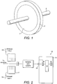
- FIG. 1 shows a typical existing flywheel arrangement.
- a substantially circular central metallic support section 1 can be axially mounted on a central support such as a shaft 3.
- At least one composite ring 2 is mounted on the central support section 1.
- the composite ring 2 is filament wound from carbon fibre.
- a flywheel device such as the one shown in Figure 1 can be used as a mechanical battery to store kinetic energy for use, for example, within a motor vehicle.
- FIG. 2 shows a possible arrangement for providing energy to a flywheel in a vehicle for storage.
- the system 10 includes a flywheel 12 arranged in a vacuum 14, in order to optimise operation of the flywheel 10 by removing the friction that would otherwise be caused by air resistance.
- a clutch 16 Outside the vacuum 14, in connection with the flywheel 12, is a clutch 16.
- the clutch 16 employed may be a simple clutch of any suitable type, even a magnetic clutch.
- an input 18 is provided to the flywheel 12 via the clutch 16.
- the input channels exhaust gas energy from the combustion engine of the vehicle in which the flywheel system 10 is provided to the flywheel 12, and enables that exhaust gas energy to be stored in the flywheel 12.
- the arrangement also includes a suitable output 20 for the exhaust gas, such that supply of exhaust gas energy to the flywheel 12 can be manipulated and controlled.
- the present embodiments harness the energy with exhaust gas and enable it to be stored for future use.
- Any suitable device for recovering the exhaust energy and directing it to the flywheel 12 may be provided.
- a Tesla turbine device (not shown) may be employed to use the exhaust gas as a motive agent and recover exhaust energy therefrom.
- a Tesla turbine or disc turbine
- gas or fluid flow in a Tesla turbine is radial, travelling in a circular or spiral path.
- the flow of exhaust gas to the clutch 16 and flywheel 12 may be controlled by varying the axial separation of the discs of a Tesla turbine, in order to increase or decrease the volume of gas being transmitted therethrough and input to the clutch 16, per unit time.
- VGT variable geometry turbo charger
- a VGT may be advantageously employed to utilize excess exhaust gas energy via the flywheel 12 such that the energy therein may be stored for future use.
- the clutch 16 is provided between the flywheel 12 and a variable ratio system 22.
- a variable ratio system may include a variator device such as a continuously variable transmission (CVT) or infinitely variable transmission (IVT) or a comparative electric machine arrangement.
- the variable ratio system 22 in Figure 2 leads to the driveline of the vehicle, such that the flywheel device 12 is mechanically coupled to the internal combustion engine (ICE) of the vehicle to provide a mechanical hybrid drive system.
- ICE internal combustion engine
- the flywheel 12 could alternatively or additionally be used for other purposes including direct drive, charging other battery types, and/or powering vehicle outputs other than the driveline, whilst still being arranged to be charged by the exhaust gas stream of the vehicle.
- the clutch should be capable of engaging to synchronise the flywheel (12) input and the turbine element in the arrangement as shown in Figure 2 . It therefore should engage in a slipping state and therefore dissipate a small amount of energy.
- a lightweight low-inertia dry-type single plate or cone type-clutch could be used as a straight-forward solution.
- More compact solutions include an electromechanical particle clutch which is used on a/c compressor and supercharger drives but typically has a fairly low speed range or a wrap spring clutch device which, being a one way device, will only provide torque to the flywheel preventing any drag losses from the turbine when the engine is not "on-boost".
- variable ratio system When synchronised by the variable ratio system (22), the turbine will spin at flywheel speed and therefore variable inlet geometry could be used to optimise the turbine efficiency based on operating conditions including flywheel speed, exhaust mass flow rate, and exhaust manifold pressure.
- the flywheel 12 does not require any additional energy source such as an electric motor in order to initiate charging or top it up, but instead continual auxiliary charging of the flywheel system is provided by making use of existing exhaust gas energy which would otherwise be wasted in a conventional vehicle system.
- the flywheel performance is not limited by turbo lag.
- the energy in the flywheel 12 does not need to be used immediately but can be stored for future use in a variety of applications within a vehicle, as will be understood further from the descriptions below.
- the mechanism as illustrated in Figure 2 uses exhaust gas flow in which there is kinetic energy and provides it for storage in a flywheel also as kinetic energy, losses due to conversion between energy types are reduced.
- the flywheel 12 can be placed in the wastegate loop of a turbocharger.
- a turbocharger is a passive device placed in the exhaust gas stream in a vehicle or engine, the purpose of which is to direct exhaust gas energy to a compressor to increase this pressure therein.
- the turbo charger has a wastegate in order to release excess gas therefrom, hence helping to optimise both the engine boost pressure and the exhaust manifold pressure at different system operating points.
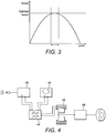
- FIG. 3 the boost-load relationship for a conventional turbocharger is illustrated. It can be seen that the turbocharger produces an optimal ideal boost for the associated internal combustion engine only for a small range of engine loads. However using a flywheel 12 to drive the compressor of a turbocharger, in combination with the turbocharger turbine, acts to optimise boost over a greater range of loads and hence flatten the curve shown in Figure 3 . Thus improved turbocharger efficiency is achieved.
- a flywheel As well as being operable for use with a turbocharger, a flywheel according to the present embodiments may be used in order to drive a supercharger device for a vehicle.
- known supercharger devices operate by using engine power in order to drive the compressor of the supercharger and boost charge pressure in a vehicle. This direct use of engine power causes parasitic losses, hence compromising the potential efficiency of the vehicle in operation.
- a flywheel device can be used to drive a charge boosting device such as a supercharger in order to boost engine charge pressure without directly taking power from the engine, thus avoiding parasitic losses that are typically associated with superchargers.
- the flywheel can be charged using exhaust gas energy, as discussed above.
- energy may be recovered from the driveline of a vehicle, for example during regenerative braking or engine load levelling, and stored in an auxiliary flywheel device for use in driving a supercharger.
- Energy may be recovered from the power train through any suitable mechanical linkage such as a variator, also discussed above.
- a supercharger is coupled to the driveline of the vehicle.
- the flywheel acts as a torque supply to the supercharger, therefore enabling energy stored in the flywheel to be supplied indirectly to the driveline via the ICE.
- the mechanical linkage used between the flywheel and the supercharger may include a clutch as discussed above in relation to the exhaust driven flywheel aspect.
- an overdrive clutch could be used, whereby turbine energy is used directly in the conventional sense to drive the compressor when it is up to speed and flywheel energy is only used when the turbine is idling (i.e. low engine speed). This requires an overrun clutch which only drives in one direction, for example a wrap spring clutch.
- flywheel This is particularly effective for electro-magnetic flywheel configurations in which speeds do not need to match - the flywheel is then charged from the turbine via an electrical path when the turbine is over-boosting at high engine speeds.
- the flywheel drives the compressor at low engine speeds also via an electrical path.
- the flywheel is charged using driveline energy and/or exhaust gas, energy that would otherwise be wasted in a conventional system is instead harnessed.
- energy that would otherwise be wasted in a conventional system is instead harnessed.
- the overall performance of the vehicle is improved.
- performance benefits are provided with respect to both fuel consumption and vehicle emissions.
- the auxiliary flywheel device can be used as the sole energy source for the supercharger or can be used as an add-on to an existing supercharger energy source. For example, it can provide power boosting to a supercharger at low engine speeds, at which point it is not preferable to use direct engine power for supercharging purposes. Therefore, because the flywheel is operable to enhance power supply to a supercharger, the supercharger can provide an ideal inlet pressure and mass flow into an ICE regardless of the operating engine speed of the vehicle, and in sympathy with any mass flow being provided by a turbo system (if present) at that time. Put another way, the flywheel driven supercharger can provide optimal charge boost at any point of the engine operating map for a vehicle. This provides particular advantages for driving manoeuvres such as pull away, which benefit from an immediate short-term surge of energy when engine exhaust mass flow is low and power is otherwise low, especially in a highly boosted engine.
- flywheel driven supercharger allows for downsizing of an engine since the engine power density during low exhaust mass flow events such as pull away, described above, is improved.
- the reduction in size reduces friction and pumping losses, thereby improving its efficiency. It is anticipated that, by actively controlling the mass flow into the cylinder of an engine to optimum in all conditions, the flywheel driven supercharger could result in up to a 30% reduction in fuel consumption for an engine even without downsizing. Downsizing the engine will therefore enhance this potential fuel consumption advantage and also satisfy the growing consumer trend for achieving maximum performance from as small, compact and low cost an ICE as possible.
- flywheel driven supercharger are particularly pronounced for diesel engines for which there is typically more gaseous mass in the chamber to be compressed and expanded than would be the case for gasoline engines.
- ideal inlet pressure varies between engine and vehicle types, and can be derived, for example from the design load map for such a vehicle.
- FIG. 4 shows a possible layout for another flywheel use according to a further aspect of the present application.
- a configuration is shown for using mechanical flywheel energy storage in parallel with a conventional plug-in chemical battery system.
- the mechanical 40 battery comprising the flywheel can be used, for example, to handle regenerative braking energy recovery as an alternative to this function being performed using the chemical battery 42.
- regenerative braking and recovery during a typical vehicle usage scenario tends to require high power and frequency cycling of the battery system charge level for a hybrid vehicle or machine. Such high frequency cycling can have significant negative effects on chemical batteries, deteriorating their health and limiting the life of the overall system.
- a mechanical flywheel battery 40 operates in parallel with a chemical battery 42, feeding into the power electronics 44 of an electric machine 46 which, in turn, is arranged to provide power to the hybrid driveline 48 of a vehicle.
- the arrangement as shown in Figure 4 is not limited to using the flywheel as the main battery for regenerative breaking.
- the flywheel battery 40 may advantageously be used as the main battery for any rapid or short-term energy supply and/or recovery during vehicle use, whereas the chemical battery 42 is more suited to lower charge rates, i.e. slower, longer-term energy supply and recovery.
- the parallel chemical 42 and mechanical 40 batteries according to the present aspect should be arranged and operated according to the same considerations as any other battery arrangement. That is, one must consider the available energy, power and lifetime of the two batteries in isolation and in combination. It should be noted that whilst Fig. 4 shows an embodiment wherein two batteries are arranged in parallel, they could also be arranged in series with the mechanical flywheel battery 40 positioned between the chemical battery 42 and the transmission of an engine.
- a first step 510 it is considered whether, at a particular moment in time, power is going into or out of a combined chemical and mechanical battery system, such as the one illustrated in Figure 4 . If, according to the vehicle user requirements and operating conditions at that time, power is to go out 512 of the battery system in order to provide power to the electric machine 46, the flywheel battery state of charge is then considered at step 514. If the flywheel battery state of charge is found to be high 516, energy will be used from the flywheel battery 40 to supply power to the electric machine 46. If, on the other hand, the flywheel battery state of charge is low 518, energy from the chemical battery 42 will instead be used.
- the flywheel battery state of charge is medium at a time at which power output is required from the battery system, it will then be considered at step 522 whether the power requirement at that time is high or low. If the power requirement is high, the energy to meet that requirement will be taken from the flywheel battery 524. However if the power requirement is low, such that a significant recharging cycle would not be required thereafter, the energy to meet the power requirement will be taken from the chemical battery 526.
- step 528 if it is decided at step 528 that power is to go into the battery system, the next consideration is whether this power-in will happen at low cycling power 530, for example during plug-in charging or otherwise slow charge maintenance, or whether the power-in is to happen at high cycling loads or power, for example during regenerative braking or engine load levelling.
- low cycling power-in the energy will be stored in the chemical battery 42.
- high cycling loads or power the energy will instead be stored in the mechanical flywheel battery 40.
- FIG. 6a illustrates energy flow during load levelling or regenerative braking, during which times energy is recovered and reused over short time intervals.
- the energy that was previously present in the vehicle as kinetic energy is recovered through the driveline into the flywheel battery, in order to avoid a cycling frequency of chemical battery charge and also, advantageously, to avoid conversion between energy types which can lead to energy dissipation.
- FIG 6d it can be seen that energy may be provided from the mechanical battery 40 to the chemical battery 42.
- Figure 6d illustrates slow charge maintenance wherein high power energy recovery from the vehicle wheels and driveline is directed to the flywheel battery 40 and thereafter low power charge from recovered flywheel energy is supplied to the chemical battery 42 for long term storage in chemical form.
- the currents flowing into the chemical battery 42 are minimised which, in turn, minimises the power loss to heat in the chemical battery 42.
- the reduction in power loss in the chemical batteries improves the system efficiency and reduces the impact of the deleterious thermal ageing effects on the cell structure, as discussed further below.
- FIG 6e illustrates energy flow for high power working of the electric machine 46.
- the chemical battery 42 which is used for long term storage of energy in chemical form, charges the flywheel 40 to enable it to provide energy to high power applications for short periods of time.
- the efficiency of energy supply for high power applications is greater from the flywheel battery than from the chemical battery, such that the flywheel battery is preferably used in isolation to provide energy to the electric machine when high power output is required from it.
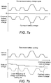
- Figures 7a and 7b show a typical battery charge cycle for a chemical battery, as compared to vehicle speed, for a conventional chemical battery working in isolation and for a chemical battery working in dual mode with a flywheel battery, respectively. It can be seen from these Figures that by using energy from a flywheel battery during periods of, for example, fast acceleration or deceleration, and thereby avoiding high power flows and high cycling frequency of charge in a chemical battery, greater stability of charge in the chemical battery is achieved.
- the mechanical flywheel energy storage device is inherently suited to short term energy storage and has no fundamental limits on the power it can deliver or receive. Therefore the present aspect utilises the strength of the mechanical system by preferably using it for short term energy storage only. Although it is anticipated that the flywheel battery might assist the chemical battery for long term energy storage purposes in exceptional circumstances.
- the use of a flywheel in dual mode with a chemical battery avoids high power flows in and out of the chemical battery, thereby preventing excessive temperature elevation in the chemical battery.
- elevation of temperature in a chemical battery over a period of time contributes to its deterioration.
- elevating the internal temperature of the chemical battery will lead to increased system inefficiency as Ohmic losses in subcomponents rise with increased Impedance, commensurate with the elevation in battery temperature.
- the overall mechanical battery/chemical battery dual-mode arrangement has an extended expected lifetime as compared to conventional chemical-only battery arrangements.
- Dual mode mechanical/chemical battery operation as described herein is not limited to use in conventional hybrid engines or to electric vehicles. Instead the principle may be applied more globally to other vehicle machinery and equipment, including lifts and cranes.
- a flywheel according to the present embodiments may be used to "fill-in" output driveline torque on a vehicle during a "torque-interrupt” caused by a gearshift event on an automated manual transmission vehicles.
- the fill-in layout and associated control methods herein address the "torque-interrupt" sensation, which can be a problem for some users, by using flywheel energy to drive or brake transmission output during a gearshift event to at least reduce or potentially eliminate the torque-interrupt feel for the user.
- FIG 8a shows a possible layout for using stored flywheel energy to provide torque fill-in.
- a flywheel motor 80 is connected to a variator 82 by a suitable isolating coupling 81.
- the variator 82 is mechanically coupled to the output of the internal combustion engine 84 downstream of its transmission 86, so that both the flywheel 80 and the engine 84 can provide energy to the final drive 88 of the vehicle.
- the power provided by or taken in by a flywheel is proportional to the angular acceleration of the flywheel, i.e. the rate of change of flywheel speed, assuming the flywheel has a constant inertia. Therefore the rate of change of torque delivered by the flywheel 80, via the variator 82, is inversely proportional to the angular acceleration of the flywheel and thus the rate of change of ratio across the variator 82.
- controlling ratio across the variator 82 alone would not provide sufficient control resolution for effective flywheel torque fill-in as required according to the present aspect.
- regulating coupling means 89 are provided between the variator 82 and its final mechanical coupling point 87 with the driveline 88.
- the torque control device including the variator 82 and regulating coupling 89 provides a fast response, in the region of less than 100 milliseconds, thus enabling immediate reaction of the flywheel 80 in providing torque fill-in to the driveline 88 when required, particularly during a gearshift event.
- the arrangement as shown in Figure 8a minimises energy dissipation and thus ensures that as much of the stored energy in the flywheel 80 ultimately is converted to effective torque fill-in in accordance with the vehicle's needs over time.
- the clutch comprised in the regulating coupling 89 can direct and control both brake torque and accelerating torque from the flywheel 80. That is, if the flywheel side element has a speed which is below the speed of the driveline side element then brake torque will result from the clutch action. Conversely, if the flywheel side element has a speed that is above the driveline side element then accelerating torque will result from the clutch action.
- the clutch used in the regulating coupling 89 may be of any suitable type including a magnetic clutch, a passively cooled dry clutch unit, a passively cooled sealed wet clutch unit with mechanical actuation device, wet clutch plates with internal passive pumping device, or a multi plate clutch.
- control strategy for flywheel torque fill-in can be understood with respect to the arrangement of Figure 8a and further with respect to Figures 8b and 8c , which also illustrate suitable configurations according to this aspect.
- the control logic includes consideration of whether the engine power is on or off during a given gearshift manoeuvre and also on whether the shift is an upshift or a downshift.
- the flywheel 80 is required to provide accelerating torque to the driveline 88. This enables the torque change at the vehicle wheels during the gearshift to be spread over the complete shift without compromising the shift time or vehicle speed.
- advantages provided are over conventional power shifting transmissions which must implement torque change at the wheels during a first torque phase before speed can be changed, thus leading to an interrupt sensation for the user.
- Figure 8d shows a possible control flow for a flywheel torque fill-in system according to the present aspect.
- the flywheel used may be of any suitable capacity.
- the flywheel motor 80 may have a capacity of 400KJ and the variator 82 used may be a CVT having 120KW capability.
- the flywheel could supply 100KW down the driveline, over a period of four seconds.
- a typical gearshift only take around a quarter of a second. Therefore not all the energy in the flywheel needs to be dissipated during any given gearshift and/or there can be overlap between flywheel torque supply and engine torque supply at the beginning and/or end of the gearshift.
- the user first initiates the gear change at step 810, typically using the clutch pedal or other in-vehicle clutch control means.
- the CVT then comes on stream to deliver power, derived from the flywheel, to the driveline during the gear change. Once this power delivery is in place, at step 820 the gear change occurs in the engine.
- the engine resumes responsibility for power delivery and, either at the same time or thereafter, at step 850 the power delivery from the flywheel and CVT is discontinued.
- the engine can overrun in order to top up the charge on the flywheel in preparation for subsequent use.
- torque change at the vehicle wheels can be spread over the complete coast down, thus ensuring smooth coasting behaviour with no shift feel.
- the fill-in flywheel device can recover kinetic energy, dependant on the drive mode of the vehicle, the main engine transmission can await positive torque before proceeding with further operations.
- flywheel configuration and control method provide a way of controlling torque delivered during a gearshift event in order to provide improved shift comfort for the user over the gearshift period.
- the flywheel fill-in system provides an efficient means of energy storage and recovery since energy between the flywheel and the driveline remains in the kinetic form, hence preventing energy dissipation that is often associated with energy conversion stages in vehicles and machinery.
- the flywheel is arranged both to provide energy to the driveline when required and to recover energy from the driveline at other points during a vehicle usage cycle, it makes use of energy that is already present in a vehicle and thus does not require an energy source in order to provide its torque fill-in function. This provides a significant advantage over, for example, electric motor fill-in systems that require an additional energy source, or at least, an energy conversion stage, in order to provide torque to the driveline.
- a flywheel and associated variator and coupling can be retrofitted to an existing automated manual transmission, thereby improving its efficiency and providing improved user comfort during gearshift events in a straightforward and relatively low cost manner.
- the package impact of retrofitting a flywheel as described herein for torque fill-in purposes in existing systems is very low since no major redesign of the system is required for doing so. Therefore the present aspect has potential for use in existing vehicles as well as in future vehicle designs.
- the function of a variator device is to match the speed of a flywheel to the speed at the mechanical coupling point at which a flywheel is coupled to the output of an ICE or other output means.
- the variator is a power translator. That is, power in the flywheel embodiments discussed above is proportional to torque multiplied by angular speed.
- the function of the variator or other power translator used is to translate how torque and low speed at one side thereof to low torque and high speed at the other side of the power translator.
- variator options for those aspects in which a variator is utilised include a belt type continuous variably transmission (CVT), a traction type CVT, a mechanical split path infinitely variable transmission (IVT), an electrical split path IVT, a hydrostatic CVT/IVT and one or more electrical motors. Indeed, the system could even be air-driven.
- FIG 9a shows a possible flywheel and variator layout that could be used, for example, for torque fill-in purposes.
- the flywheel 90 is arranged in a vacuum 92.
- the flywheel 90 connects to a coupling clutch 94 by any suitable coupling means.
- the coupling clutch 94 provides a connection between the flywheel 90 and a variator device 96.
- the variator device 96 is, in turn, mechanically coupled to the transmission input of a vehicle, between the internal combustion engine 97 and the transmission 99.
- FIG. 9b shows an alternative layout comprising a split path IVT.
- a flywheel 90 is provided preferably in a vacuum 92 and is in connection with a coupling clutch 94, which in turn connects to a variator.
- the variator device used in this arrangement includes epicyclic stages 96 and an inline traction variator 98.
- the inclusion of an IVT variator system improves the potential functionality of the flywheel assisted engine, providing increased recovery range at low speed and also enabling launch boost.
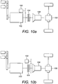
- Figures 10a to 10b further illustrate potential coupling configuration options for flywheel assist according to the presently described aspects.
- an auxiliary flywheel device 100 is coupled to the ICE 102, upstream of the main vehicle clutch 104 and transmissions 106.
- This coupling configuration provides an advantage in that a relatively narrow ratio range is needed across the variator device between the ICE 102 and the flywheel 100 in order to match flywheel speed to the speed at its coupling point with the ICE 102. That is, because the engine rotates at a higher speed than the wheels, the ratio difference between the flywheel and engine is less than that between the flywheel and the wheels. Also, the large, powerful gears needed for the transition between the flywheel and the ICE are already present in the transmission, but are not present lower downstream.
- the arrangement in Figure 10a furthermore reduces variator torque by utilising the torque advantage of the transmission.
- the clutch 104 must be closed to recover and reuse energy from the flywheel 100 in the vehicle driveline 108. Therefore energy recovery from the flywheel 100 is interruptible by gearshifts.
- power shift transmission is required in this arrangement in order to enable continuous drive and regenerative braking using the flywheel device 100 for mechanical energy storage.
- Figure 10b shows an alternative coupling configuration similar to that shown in Figure 9a , wherein the flywheel 100 is coupled to the transmission input, between the clutch 104 and the transmission 106.
- the configuration in 10b provides an improved useable range due to the compatible transmission ratios between the ICE 102 and the flywheel 100. And it also enables reduction of variator torque.
- decoupling is still required during gearshifts in order for energy recovery and/or reuse from the flywheel 100 during gearshift manoeuvres.
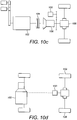
- Figure 10c illustrates another possible coupling configuration wherein the flywheel 100 is coupled at the transmission output. This arrangement is advantageous since the energy recovery from the flywheel 100 is not interrupted by gearshifts. Furthermore, there is potential for a flywheel only mode, wherein the flywheel 100 is the sole energy source and energy does not come from the ICE 102, which is possible as long as the main clutch 104 is open. However the configuration in Figure 10c has a reduced overall range of operation as compared to the configurations of Figures 10a and 10b and it also requires increased coupling torque at the variator output.
- Figure 10d shows a rear axle system wherein the flywheel 100 is provided between the engine 102 and the rear wheels 109 of a vehicle.
- this configuration is advantageous since energy recovery from the flywheel is not interrupted by gearshifts and there is potential for a flywheel only mode as long as the main clutch is open.
- the flywheel 100 may be used for four wheel drive assist or for part time four wheel drive functionality.
- the flywheel 100 could assist in diversifying the suitability of a vehicle for different driving conditions.
- the configuration in Figure 10d has a reduced overall operating range and requires increased coupling torque at the variator output as compared to the configurations shown in Figures 10a and 10b .
- flywheel in a suitable configuration as discussed above is in launch support.
- the flywheel may be the sole torque supply for launch or may be used in conjunction with the engine torque supply.
- the flywheel could be sufficient to supply torque for launch of the vehicle for each nudge forward.
- the flywheel could be used in conjunction with part of the engine capability, for example using two engine cylinders out of the four available.
- An appropriate control strategy can be put in place so that the optimum combination of flywheel and engine torque supply is used at any given time taking into account vehicle factors and potentially also environmental factors such as emissions restrictions in particular areas.
- flywheel aspects as described herein are not mutually exclusive but can be implemented in any suitable combination in a vehicle, machine or other apparatus.
- an engine layout may include a relatively small flywheel to be used for any or all of: driving a supercharger, charging a chemical battery, and providing an auxiliary energy supply or recovery in addition to that which is provided by the main power source during vehicle start or stop events.
- the same engine configuration could also include a relatively large flywheel for use in direct and/or hybrid drive of the vehicle wheels.
- the flywheel it is possible for the flywheel to be configured such that, on switch off of the vehicle or the equipment, the flywheel is run down and in doing so charges a chemical or other long term battery storage means.
- a flywheel may be included in an engine or machine during manufacture or retro-fitted to an existing engine or machine after manufacture, in a number of different configurations.
- a flywheel is implemented in an engine, vehicle, machine or apparatus in order to advantageously harness the available energy therein and use it to improve overall performance and output.
- energy which is dissipated in conventional systems can instead be usefully captured, stored and reused using a suitable flywheel arrangement.
- the flywheel arrangements herein may be suitably manipulated and controlled in order to meet changing operating conditions and user requirements over time in a straightforward and energy efficient manner.
- the flywheel can store energy in kinetic form over an extended period of time and, furthermore, can be used to supply energy in kinetic or other forms to other energy storage devices according to conditions overtime, for example, during engine switch off.
- flywheel aspects described herein provide substantial advantages over known arrangements by enabling enhanced efficiency and performance in a user friendly, cost effective, compact and environmentally friendly manner. They can be implemented in any suitable vehicle, engine, machine or apparatus in order to improve its output performance and meet user requirements in a manner not previously possible using prior art arrangements.
Landscapes
- Engineering & Computer Science (AREA)
- Transportation (AREA)
- Mechanical Engineering (AREA)
- Chemical & Material Sciences (AREA)
- Combustion & Propulsion (AREA)
- Automation & Control Theory (AREA)
- Hybrid Electric Vehicles (AREA)
- Arrangement Or Mounting Of Propulsion Units For Vehicles (AREA)
- Electric Propulsion And Braking For Vehicles (AREA)
Claims (14)
- Vorrichtung zum Zuführen von Drehmoment zu und zum Erhalten von Drehmoment von einem Triebstrang (88) eines Fahrzeugs, wobei die genannte Vorrichtung ein in einem Vakuum angeordnetes Schwungrad (80) beinhaltet, wobei das Schwungrad (80) mit einer Kupplung (81) an einem Variator (82) angeschlossen ist, der zum Übertragen von Drehmoment auf das und von dem genannte(n) Schwungrad (80) angeordnet ist, wobei der Variator (82) so angeordnet ist, dass er mechanisch mit dem Abtrieb einer primären Drehmomentzufuhr (84), der ihrem Getriebe (86) nachgeschaltet ist, gekoppelt zu werden, wobei die Vorrichtung im Gebrauch zum Zuführen und/oder zum Erhalten von Drehmoment parallel zur primären Drehmomentzufuhr (84) zu und/oder von einem gemeinsamen Fahrzeugantriebsstrang (88) angeordnet ist.
- Vorrichtung nach Anspruch 1, wobei die genannte primäre Drehmomentzufuhr eine Brennkraftmaschine (ICE) und/oder einen Elektromotor beinhaltet.
- Vorrichtung nach Anspruch 1, die ferner eine Kupplung (81, 89) aufweist, wobei die genannte Kupplung (81, 89) im Gebrauch zum Verbessern der von dem genannten Variator (82) zwischen dem Schwungrad (80) und dem Triebstrang (88) des Fahrzeugs, zu bzw. von welchem Drehmoment übertragen oder erhalten wird, angeordnet ist.
- Vorrichtung nach einem der Ansprüche 1 bis 3, wobei das genannte Schwungrad (80) unter Verwendung von aus dem Betrieb des Fahrzeugs zurückgewonnener Energie wiederaufladbar ist.
- Vorrichtung nach Anspruch 4, wobei das genannte Schwungrad (80) unter Verwendung von einem der Folgenden wiederaufladbar ist: Abgasenergie, einer chemischen Batterie, einem Elektromotor, einer Verbrennungskraftmaschine (ICE) und direkt aus dem Triebstrang des Fahrzeugs zurückgewonnener Energie.
- Vorrichtung nach einem der Ansprüche 1 bis 5, die ferner eine Steuereinheit zum Steuern der Drehmomentübertragung zu und von dem genannten Triebstrang (88) des Fahrzeugs aufweist.
- Verfahren zum Zuführen einer Drehmomentergänzung zu einem Triebstrang (88) eines Fahrzeugs, wobei das genannte Verfahren das Bereitstellen einer Vorrichtung nach einem der Ansprüche 1 bis 6, Aufladen des Schwungrads (80) in Vorbereitung auf die Drehmomentzufuhr und Übertragen von Drehmoment vom Schwungrad auf den Triebstrang des Fahrzeugs während des Fahrzeugbetriebs beinhaltet, um die Drehmomentübertragung von der primären Drehmomentzufuhr (84) zu ersetzen oder zu verbessern.
- Verfahren nach Anspruch 7, das ferner das Wiederaufladen des genannten Schwungrads (80) unter Verwendung von aus dem Betrieb des Fahrzeugs zurückgewonnener Energie aufweist.
- Verfahren nach Anspruch 7 oder Anspruch 8, das das Übertragen von Drehmoment von dem genannten Schwungrad (80) auf den Triebstrang (88) des Fahrzeugs, wenn der augenblickliche Drehmomentbedarf für den Triebstrang des Fahrzeugs einen Schwellenwert übersteigt, aufweist.
- Verfahren nach einem der Ansprüche 7 bis 9, das das Übertragen von Drehmoment von dem genannten Schwungrad (80) auf den Triebstrang (88) des Fahrzeugs während einer Zeitspanne reduzierter Drehmomentübertragung von der primären Drehmomentzufuhr (84) aufweist.
- Verfahren nach einem der Ansprüche 7 bis 10, das ferner das Übertragen von Drehmoment vom Triebstrang (88) des Fahrzeugs auf das Schwungrad (80) und/oder auf die primäre Drehmomentzufuhr (84) aufweist.
- Verfahren nach einem der Ansprüche 7 bis 11, wobei die genannte mechanische primäre Drehmomentzufuhr (84) eine Verbrennungskraftmaschine ist und wobei das genannte Verfahren das Verwenden des Schwungrads (80) als einzige Drehmomentzufuhr zum Triebstrang (88) des Fahrzeugs während eines Teils eines Fahrzeuggangschaltereignisses umfasst.
- Verfahren nach Anspruch 12, das ferner das Ersetzen, nach Abschluss des Fahrzeuggangschaltereignisses, des Schwungrads (80) durch die Verbrennungskraftmaschine (84) als die einzige Drehmomentzufuhr zum Triebstrang (88) aufweist.
- Verfahren nach Anspruch 12 oder Anspruch 13, das ferner das Verwenden, nach Abschluss der Gangumschaltung, der Verbrennungskraftmaschine (84) zum Wiederaufladen des Schwungrads (80) aufweist.
Applications Claiming Priority (2)
| Application Number | Priority Date | Filing Date | Title |
|---|---|---|---|
| GB0918380A GB0918380D0 (en) | 2009-10-20 | 2009-10-20 | Torque fill-in |
| PCT/EP2010/065730 WO2011048102A1 (en) | 2009-10-20 | 2010-10-19 | Apparatus and method for torque fill-in |
Publications (2)
| Publication Number | Publication Date |
|---|---|
| EP2490909A1 EP2490909A1 (de) | 2012-08-29 |
| EP2490909B1 true EP2490909B1 (de) | 2017-08-30 |
Family
ID=41462642
Family Applications (1)
| Application Number | Title | Priority Date | Filing Date |
|---|---|---|---|
| EP10775750.2A Not-in-force EP2490909B1 (de) | 2009-10-20 | 2010-10-19 | Vorrichtung und verfahren zum drehmomentergänzung |
Country Status (4)
| Country | Link |
|---|---|
| EP (1) | EP2490909B1 (de) |
| CN (1) | CN102666168A (de) |
| GB (1) | GB0918380D0 (de) |
| WO (1) | WO2011048102A1 (de) |
Cited By (1)
| Publication number | Priority date | Publication date | Assignee | Title |
|---|---|---|---|---|
| EP4431326A1 (de) * | 2023-03-16 | 2024-09-18 | Yanmar Holdings Co., Ltd. | Energiespeichervorrichtung und arbeitsmaschine |
Families Citing this family (8)
| Publication number | Priority date | Publication date | Assignee | Title |
|---|---|---|---|---|
| DE102012018416B4 (de) * | 2012-09-12 | 2015-04-23 | Getrag Getriebe- Und Zahnradfabrik Hermann Hagenmeyer Gmbh & Cie Kg | Verfahren zum Ansteuern eines Hybridantriebsstranges |
| GB2530823A (en) * | 2014-05-16 | 2016-04-06 | Flybrid Automotive Ltd | Controlled cooling of a frictional engagement device in an energy recovery system |
| EP2955418B1 (de) | 2014-06-13 | 2019-02-20 | Perkins Engines Company Limited | Variatorunterstütztes Getriebe |
| GB2544177B (en) | 2015-03-12 | 2018-04-04 | Flybrid Automotive Ltd | Transmission for energy storage device |
| CN105730446B (zh) * | 2016-02-22 | 2018-06-01 | 江苏大学 | 一种蓄电池与飞轮联合式怠速和制动能量回收系统 |
| EP3257695A1 (de) * | 2016-06-14 | 2017-12-20 | Perkins Engines Company Limited | System zur rückgewinnung von kinetischer energie |
| GB2572777A (en) * | 2018-04-10 | 2019-10-16 | Caterpillar Inc | Energy storage system for powertrains of machines |
| CN120552593B (zh) * | 2025-07-30 | 2025-10-31 | 遂宁云内动力机械制造有限公司 | 混合动力系统传动机构及混合动力系统 |
Family Cites Families (10)
| Publication number | Priority date | Publication date | Assignee | Title |
|---|---|---|---|---|
| US4588040A (en) * | 1983-12-22 | 1986-05-13 | Albright Jr Harold D | Hybrid power system for driving a motor vehicle |
| US6177734B1 (en) * | 1998-02-27 | 2001-01-23 | Isad Electronic Systems Gmbh & Co. Kg | Starter/generator for an internal combustion engine, especially an engine of a motor vehicle |
| SK285701B6 (sk) * | 1997-03-11 | 2007-06-07 | Robert Bosch Gmbh | Poháňací agregát na motorové vozidlá so spaľovacím motorom |
| DE10209514B4 (de) * | 2001-03-30 | 2016-06-09 | Schaeffler Technologies AG & Co. KG | Antriebsstrang |
| WO2006126876A2 (en) * | 2005-05-25 | 2006-11-30 | Dti Group B.V. | Method for regulating the drive torque to the wheels of a vehicle |
| US7341534B2 (en) * | 2005-09-01 | 2008-03-11 | General Motors Corporation | Electrically variable hybrid transmission and powertrain |
| GB2440996A (en) * | 2006-05-25 | 2008-02-20 | Powertrain Technology Ltd | Power transmission system |
| US7540346B2 (en) * | 2006-10-19 | 2009-06-02 | Loong-Chiang Hu | Automotive vehicle employing kinetic energy storage/reuse capability |
| WO2009010819A1 (en) * | 2007-07-17 | 2009-01-22 | Renault Trucks | Powertrain comprising an optimized energy recovery system |
| DE102008000327A1 (de) * | 2008-02-18 | 2009-08-20 | Zf Friedrichshafen Ag | Einrichtung zur Reduzierung des Zugkrafteinbruchs |
-
2009
- 2009-10-20 GB GB0918380A patent/GB0918380D0/en not_active Ceased
-
2010
- 2010-10-19 WO PCT/EP2010/065730 patent/WO2011048102A1/en not_active Ceased
- 2010-10-19 EP EP10775750.2A patent/EP2490909B1/de not_active Not-in-force
- 2010-10-19 CN CN2010800565647A patent/CN102666168A/zh active Pending
Non-Patent Citations (1)
| Title |
|---|
| None * |
Cited By (3)
| Publication number | Priority date | Publication date | Assignee | Title |
|---|---|---|---|---|
| EP4431326A1 (de) * | 2023-03-16 | 2024-09-18 | Yanmar Holdings Co., Ltd. | Energiespeichervorrichtung und arbeitsmaschine |
| US20240309609A1 (en) * | 2023-03-16 | 2024-09-19 | Yanmar Holdings Co., Ltd. | Energy storage device and work machine |
| US12420623B2 (en) * | 2023-03-16 | 2025-09-23 | Yanmar Holdings Co., Ltd. | Energy storage device and work machine |
Also Published As
| Publication number | Publication date |
|---|---|
| EP2490909A1 (de) | 2012-08-29 |
| CN102666168A (zh) | 2012-09-12 |
| WO2011048102A1 (en) | 2011-04-28 |
| GB0918380D0 (en) | 2009-12-02 |
Similar Documents
| Publication | Publication Date | Title |
|---|---|---|
| US20120262105A1 (en) | dual-mode battery | |
| US20130042617A1 (en) | Energy control | |
| US9718343B2 (en) | Energy storage system having a flywheel for a vehicle transmission | |
| EP2490909B1 (de) | Vorrichtung und verfahren zum drehmomentergänzung | |
| US8474556B2 (en) | Hybrid power output system | |
| CN102015401B (zh) | 用于在车辆中进行换档的方法和动力传动系 | |
| CA2850063C (en) | Flywheel hybrid system | |
| CN101209667A (zh) | 混合动力输出装置 | |
| US20120137681A1 (en) | Vehicle Comprising a Charged Combustion Engine and Method for Operating a Vehicle Comprising a Charged Combustion Engine | |
| CN102753414B (zh) | 混合动力车辆机动化设备的控制方法以及相关联的设备 | |
| US20120329603A1 (en) | Hybrid vehicle | |
| CN101980882A (zh) | 机动车传动系 | |
| TWI584974B (zh) | 引擎定速運轉結合可控變速之動力系統 | |
| JP2012126197A (ja) | ハイブリッド車両 | |
| CN112793431B (zh) | 基于飞轮动力的燃料电池汽车动力总成系统 | |
| CN102390248A (zh) | 单离合器混合动力系统 | |
| US8845469B2 (en) | High efficiency hybrid vehicle with two planetary gear mechanisms for power derivation | |
| Hattori et al. | Functional design of a motor integrated CVT for a parallel HEV | |
| CN215204445U (zh) | 基于飞轮动力的燃料电池汽车动力总成系统 | |
| GB2374844A (en) | A series or parallel hybrid drive | |
| US20240317190A1 (en) | Mechanical energy storage speed change method and device |
Legal Events
| Date | Code | Title | Description |
|---|---|---|---|
| PUAI | Public reference made under article 153(3) epc to a published international application that has entered the european phase |
Free format text: ORIGINAL CODE: 0009012 |
|
| 17P | Request for examination filed |
Effective date: 20120517 |
|
| AK | Designated contracting states |
Kind code of ref document: A1 Designated state(s): AL AT BE BG CH CY CZ DE DK EE ES FI FR GB GR HR HU IE IS IT LI LT LU LV MC MK MT NL NO PL PT RO RS SE SI SK SM TR |
|
| DAX | Request for extension of the european patent (deleted) | ||
| GRAP | Despatch of communication of intention to grant a patent |
Free format text: ORIGINAL CODE: EPIDOSNIGR1 |
|
| INTG | Intention to grant announced |
Effective date: 20170323 |
|
| GRAS | Grant fee paid |
Free format text: ORIGINAL CODE: EPIDOSNIGR3 |
|
| GRAA | (expected) grant |
Free format text: ORIGINAL CODE: 0009210 |
|
| AK | Designated contracting states |
Kind code of ref document: B1 Designated state(s): AL AT BE BG CH CY CZ DE DK EE ES FI FR GB GR HR HU IE IS IT LI LT LU LV MC MK MT NL NO PL PT RO RS SE SI SK SM TR |
|
| REG | Reference to a national code |
Ref country code: GB Ref legal event code: FG4D |
|
| REG | Reference to a national code |
Ref country code: CH Ref legal event code: EP |
|
| REG | Reference to a national code |
Ref country code: AT Ref legal event code: REF Ref document number: 923161 Country of ref document: AT Kind code of ref document: T Effective date: 20170915 |
|
| REG | Reference to a national code |
Ref country code: IE Ref legal event code: FG4D |
|
| REG | Reference to a national code |
Ref country code: DE Ref legal event code: R096 Ref document number: 602010044858 Country of ref document: DE |
|
| REG | Reference to a national code |
Ref country code: FR Ref legal event code: PLFP Year of fee payment: 8 |
|
| REG | Reference to a national code |
Ref country code: NL Ref legal event code: MP Effective date: 20170830 |
|
| REG | Reference to a national code |
Ref country code: LT Ref legal event code: MG4D |
|
| REG | Reference to a national code |
Ref country code: AT Ref legal event code: MK05 Ref document number: 923161 Country of ref document: AT Kind code of ref document: T Effective date: 20170830 |
|
| PG25 | Lapsed in a contracting state [announced via postgrant information from national office to epo] |
Ref country code: FI Free format text: LAPSE BECAUSE OF FAILURE TO SUBMIT A TRANSLATION OF THE DESCRIPTION OR TO PAY THE FEE WITHIN THE PRESCRIBED TIME-LIMIT Effective date: 20170830 Ref country code: SE Free format text: LAPSE BECAUSE OF FAILURE TO SUBMIT A TRANSLATION OF THE DESCRIPTION OR TO PAY THE FEE WITHIN THE PRESCRIBED TIME-LIMIT Effective date: 20170830 Ref country code: HR Free format text: LAPSE BECAUSE OF FAILURE TO SUBMIT A TRANSLATION OF THE DESCRIPTION OR TO PAY THE FEE WITHIN THE PRESCRIBED TIME-LIMIT Effective date: 20170830 Ref country code: NO Free format text: LAPSE BECAUSE OF FAILURE TO SUBMIT A TRANSLATION OF THE DESCRIPTION OR TO PAY THE FEE WITHIN THE PRESCRIBED TIME-LIMIT Effective date: 20171130 Ref country code: AT Free format text: LAPSE BECAUSE OF FAILURE TO SUBMIT A TRANSLATION OF THE DESCRIPTION OR TO PAY THE FEE WITHIN THE PRESCRIBED TIME-LIMIT Effective date: 20170830 Ref country code: LT Free format text: LAPSE BECAUSE OF FAILURE TO SUBMIT A TRANSLATION OF THE DESCRIPTION OR TO PAY THE FEE WITHIN THE PRESCRIBED TIME-LIMIT Effective date: 20170830 |
|
| PGFP | Annual fee paid to national office [announced via postgrant information from national office to epo] |
Ref country code: DE Payment date: 20171030 Year of fee payment: 8 Ref country code: FR Payment date: 20171031 Year of fee payment: 8 |
|
| PG25 | Lapsed in a contracting state [announced via postgrant information from national office to epo] |
Ref country code: IS Free format text: LAPSE BECAUSE OF FAILURE TO SUBMIT A TRANSLATION OF THE DESCRIPTION OR TO PAY THE FEE WITHIN THE PRESCRIBED TIME-LIMIT Effective date: 20171230 Ref country code: BG Free format text: LAPSE BECAUSE OF FAILURE TO SUBMIT A TRANSLATION OF THE DESCRIPTION OR TO PAY THE FEE WITHIN THE PRESCRIBED TIME-LIMIT Effective date: 20171130 Ref country code: RS Free format text: LAPSE BECAUSE OF FAILURE TO SUBMIT A TRANSLATION OF THE DESCRIPTION OR TO PAY THE FEE WITHIN THE PRESCRIBED TIME-LIMIT Effective date: 20170830 Ref country code: LV Free format text: LAPSE BECAUSE OF FAILURE TO SUBMIT A TRANSLATION OF THE DESCRIPTION OR TO PAY THE FEE WITHIN THE PRESCRIBED TIME-LIMIT Effective date: 20170830 Ref country code: GR Free format text: LAPSE BECAUSE OF FAILURE TO SUBMIT A TRANSLATION OF THE DESCRIPTION OR TO PAY THE FEE WITHIN THE PRESCRIBED TIME-LIMIT Effective date: 20171201 Ref country code: ES Free format text: LAPSE BECAUSE OF FAILURE TO SUBMIT A TRANSLATION OF THE DESCRIPTION OR TO PAY THE FEE WITHIN THE PRESCRIBED TIME-LIMIT Effective date: 20170830 |
|
| PG25 | Lapsed in a contracting state [announced via postgrant information from national office to epo] |
Ref country code: NL Free format text: LAPSE BECAUSE OF FAILURE TO SUBMIT A TRANSLATION OF THE DESCRIPTION OR TO PAY THE FEE WITHIN THE PRESCRIBED TIME-LIMIT Effective date: 20170830 |
|
| PG25 | Lapsed in a contracting state [announced via postgrant information from national office to epo] |
Ref country code: DK Free format text: LAPSE BECAUSE OF FAILURE TO SUBMIT A TRANSLATION OF THE DESCRIPTION OR TO PAY THE FEE WITHIN THE PRESCRIBED TIME-LIMIT Effective date: 20170830 Ref country code: CZ Free format text: LAPSE BECAUSE OF FAILURE TO SUBMIT A TRANSLATION OF THE DESCRIPTION OR TO PAY THE FEE WITHIN THE PRESCRIBED TIME-LIMIT Effective date: 20170830 Ref country code: RO Free format text: LAPSE BECAUSE OF FAILURE TO SUBMIT A TRANSLATION OF THE DESCRIPTION OR TO PAY THE FEE WITHIN THE PRESCRIBED TIME-LIMIT Effective date: 20170830 Ref country code: PL Free format text: LAPSE BECAUSE OF FAILURE TO SUBMIT A TRANSLATION OF THE DESCRIPTION OR TO PAY THE FEE WITHIN THE PRESCRIBED TIME-LIMIT Effective date: 20170830 |
|
| PG25 | Lapsed in a contracting state [announced via postgrant information from national office to epo] |
Ref country code: SM Free format text: LAPSE BECAUSE OF FAILURE TO SUBMIT A TRANSLATION OF THE DESCRIPTION OR TO PAY THE FEE WITHIN THE PRESCRIBED TIME-LIMIT Effective date: 20170830 Ref country code: SK Free format text: LAPSE BECAUSE OF FAILURE TO SUBMIT A TRANSLATION OF THE DESCRIPTION OR TO PAY THE FEE WITHIN THE PRESCRIBED TIME-LIMIT Effective date: 20170830 Ref country code: IT Free format text: LAPSE BECAUSE OF FAILURE TO SUBMIT A TRANSLATION OF THE DESCRIPTION OR TO PAY THE FEE WITHIN THE PRESCRIBED TIME-LIMIT Effective date: 20170830 Ref country code: EE Free format text: LAPSE BECAUSE OF FAILURE TO SUBMIT A TRANSLATION OF THE DESCRIPTION OR TO PAY THE FEE WITHIN THE PRESCRIBED TIME-LIMIT Effective date: 20170830 Ref country code: MC Free format text: LAPSE BECAUSE OF FAILURE TO SUBMIT A TRANSLATION OF THE DESCRIPTION OR TO PAY THE FEE WITHIN THE PRESCRIBED TIME-LIMIT Effective date: 20170830 |
|
| REG | Reference to a national code |
Ref country code: CH Ref legal event code: PL Ref country code: DE Ref legal event code: R097 Ref document number: 602010044858 Country of ref document: DE |
|
| PLBE | No opposition filed within time limit |
Free format text: ORIGINAL CODE: 0009261 |
|
| STAA | Information on the status of an ep patent application or granted ep patent |
Free format text: STATUS: NO OPPOSITION FILED WITHIN TIME LIMIT |
|
| REG | Reference to a national code |
Ref country code: IE Ref legal event code: MM4A |
|
| PG25 | Lapsed in a contracting state [announced via postgrant information from national office to epo] |
Ref country code: LU Free format text: LAPSE BECAUSE OF NON-PAYMENT OF DUE FEES Effective date: 20171019 Ref country code: LI Free format text: LAPSE BECAUSE OF NON-PAYMENT OF DUE FEES Effective date: 20171031 Ref country code: CH Free format text: LAPSE BECAUSE OF NON-PAYMENT OF DUE FEES Effective date: 20171031 |
|
| 26N | No opposition filed |
Effective date: 20180531 |
|
| REG | Reference to a national code |
Ref country code: BE Ref legal event code: MM Effective date: 20171031 |
|
| PG25 | Lapsed in a contracting state [announced via postgrant information from national office to epo] |
Ref country code: BE Free format text: LAPSE BECAUSE OF NON-PAYMENT OF DUE FEES Effective date: 20171031 Ref country code: SI Free format text: LAPSE BECAUSE OF FAILURE TO SUBMIT A TRANSLATION OF THE DESCRIPTION OR TO PAY THE FEE WITHIN THE PRESCRIBED TIME-LIMIT Effective date: 20170830 |
|
| PG25 | Lapsed in a contracting state [announced via postgrant information from national office to epo] |
Ref country code: MT Free format text: LAPSE BECAUSE OF NON-PAYMENT OF DUE FEES Effective date: 20171019 |
|
| PG25 | Lapsed in a contracting state [announced via postgrant information from national office to epo] |
Ref country code: IE Free format text: LAPSE BECAUSE OF NON-PAYMENT OF DUE FEES Effective date: 20171019 |
|
| RIC2 | Information provided on ipc code assigned after grant |
Ipc: B60K 6/365 20071001ALI20110510BHEP Ipc: B60K 6/10 20060101AFI20110510BHEP Ipc: B60K 6/30 20071001ALI20110510BHEP Ipc: B60W 10/10 20120101ALI20110510BHEP Ipc: B60W 20/00 20160101ALI20110510BHEP Ipc: B60K 6/48 20071001ALI20110510BHEP Ipc: B60K 6/36 20071001ALI20110510BHEP |
|
| REG | Reference to a national code |
Ref country code: DE Ref legal event code: R119 Ref document number: 602010044858 Country of ref document: DE |
|
| PG25 | Lapsed in a contracting state [announced via postgrant information from national office to epo] |
Ref country code: HU Free format text: LAPSE BECAUSE OF FAILURE TO SUBMIT A TRANSLATION OF THE DESCRIPTION OR TO PAY THE FEE WITHIN THE PRESCRIBED TIME-LIMIT; INVALID AB INITIO Effective date: 20101019 |
|
| PG25 | Lapsed in a contracting state [announced via postgrant information from national office to epo] |
Ref country code: DE Free format text: LAPSE BECAUSE OF NON-PAYMENT OF DUE FEES Effective date: 20190501 |
|
| PG25 | Lapsed in a contracting state [announced via postgrant information from national office to epo] |
Ref country code: FR Free format text: LAPSE BECAUSE OF NON-PAYMENT OF DUE FEES Effective date: 20181031 |
|
| PG25 | Lapsed in a contracting state [announced via postgrant information from national office to epo] |
Ref country code: CY Free format text: LAPSE BECAUSE OF NON-PAYMENT OF DUE FEES Effective date: 20170830 |
|
| PG25 | Lapsed in a contracting state [announced via postgrant information from national office to epo] |
Ref country code: MK Free format text: LAPSE BECAUSE OF FAILURE TO SUBMIT A TRANSLATION OF THE DESCRIPTION OR TO PAY THE FEE WITHIN THE PRESCRIBED TIME-LIMIT Effective date: 20170830 |
|
| PG25 | Lapsed in a contracting state [announced via postgrant information from national office to epo] |
Ref country code: TR Free format text: LAPSE BECAUSE OF FAILURE TO SUBMIT A TRANSLATION OF THE DESCRIPTION OR TO PAY THE FEE WITHIN THE PRESCRIBED TIME-LIMIT Effective date: 20170830 |
|
| PGFP | Annual fee paid to national office [announced via postgrant information from national office to epo] |
Ref country code: GB Payment date: 20191017 Year of fee payment: 10 |
|
| PG25 | Lapsed in a contracting state [announced via postgrant information from national office to epo] |
Ref country code: PT Free format text: LAPSE BECAUSE OF FAILURE TO SUBMIT A TRANSLATION OF THE DESCRIPTION OR TO PAY THE FEE WITHIN THE PRESCRIBED TIME-LIMIT Effective date: 20170830 |
|
| PG25 | Lapsed in a contracting state [announced via postgrant information from national office to epo] |
Ref country code: AL Free format text: LAPSE BECAUSE OF FAILURE TO SUBMIT A TRANSLATION OF THE DESCRIPTION OR TO PAY THE FEE WITHIN THE PRESCRIBED TIME-LIMIT Effective date: 20170830 |
|
| GBPC | Gb: european patent ceased through non-payment of renewal fee |
Effective date: 20201019 |
|
| PG25 | Lapsed in a contracting state [announced via postgrant information from national office to epo] |
Ref country code: GB Free format text: LAPSE BECAUSE OF NON-PAYMENT OF DUE FEES Effective date: 20201019 |