EP2490634B1 - Therapeutic wrap - Google Patents
Therapeutic wrap Download PDFInfo
- Publication number
- EP2490634B1 EP2490634B1 EP10825789.0A EP10825789A EP2490634B1 EP 2490634 B1 EP2490634 B1 EP 2490634B1 EP 10825789 A EP10825789 A EP 10825789A EP 2490634 B1 EP2490634 B1 EP 2490634B1
- Authority
- EP
- European Patent Office
- Prior art keywords
- wrap
- bladder
- insulating member
- modular
- fluid
- Prior art date
- Legal status (The legal status is an assumption and is not a legal conclusion. Google has not performed a legal analysis and makes no representation as to the accuracy of the status listed.)
- Active
Links
- 230000001225 therapeutic effect Effects 0.000 title description 5
- 239000012530 fluid Substances 0.000 claims description 102
- 238000002560 therapeutic procedure Methods 0.000 claims description 50
- 238000012546 transfer Methods 0.000 claims description 31
- 230000007423 decrease Effects 0.000 claims description 5
- 239000000463 material Substances 0.000 description 66
- 239000007788 liquid Substances 0.000 description 39
- 230000006835 compression Effects 0.000 description 18
- 238000007906 compression Methods 0.000 description 18
- 238000000034 method Methods 0.000 description 16
- 239000002826 coolant Substances 0.000 description 14
- 230000008878 coupling Effects 0.000 description 12
- 238000010168 coupling process Methods 0.000 description 12
- 238000005859 coupling reaction Methods 0.000 description 12
- 238000004519 manufacturing process Methods 0.000 description 12
- 239000004744 fabric Substances 0.000 description 10
- 238000001816 cooling Methods 0.000 description 9
- 238000009413 insulation Methods 0.000 description 9
- 238000000576 coating method Methods 0.000 description 8
- 229920002635 polyurethane Polymers 0.000 description 8
- 210000004712 air sac Anatomy 0.000 description 7
- 230000000694 effects Effects 0.000 description 7
- 239000004814 polyurethane Substances 0.000 description 7
- 239000004677 Nylon Substances 0.000 description 6
- 238000010276 construction Methods 0.000 description 6
- 210000002683 foot Anatomy 0.000 description 6
- 210000002414 leg Anatomy 0.000 description 6
- 230000013011 mating Effects 0.000 description 6
- 229920001778 nylon Polymers 0.000 description 6
- 239000000758 substrate Substances 0.000 description 6
- 238000003466 welding Methods 0.000 description 6
- 210000003423 ankle Anatomy 0.000 description 5
- 230000008901 benefit Effects 0.000 description 5
- 239000011248 coating agent Substances 0.000 description 5
- 210000003127 knee Anatomy 0.000 description 5
- 238000012986 modification Methods 0.000 description 5
- 230000004048 modification Effects 0.000 description 5
- 241000283073 Equus caballus Species 0.000 description 3
- 239000008280 blood Substances 0.000 description 3
- 210000004369 blood Anatomy 0.000 description 3
- 210000000988 bone and bone Anatomy 0.000 description 3
- 208000014674 injury Diseases 0.000 description 3
- 239000004745 nonwoven fabric Substances 0.000 description 3
- -1 polyethylene Polymers 0.000 description 3
- 239000002759 woven fabric Substances 0.000 description 3
- 206010030113 Oedema Diseases 0.000 description 2
- 208000027418 Wounds and injury Diseases 0.000 description 2
- 239000000853 adhesive Substances 0.000 description 2
- 230000001070 adhesive effect Effects 0.000 description 2
- 230000000845 anti-microbial effect Effects 0.000 description 2
- 230000006378 damage Effects 0.000 description 2
- 230000003247 decreasing effect Effects 0.000 description 2
- 238000010438 heat treatment Methods 0.000 description 2
- 238000003780 insertion Methods 0.000 description 2
- 230000037431 insertion Effects 0.000 description 2
- 239000003550 marker Substances 0.000 description 2
- 230000007246 mechanism Effects 0.000 description 2
- 230000037361 pathway Effects 0.000 description 2
- 238000000015 thermotherapy Methods 0.000 description 2
- 210000001519 tissue Anatomy 0.000 description 2
- 241000894006 Bacteria Species 0.000 description 1
- 208000001034 Frostbite Diseases 0.000 description 1
- 241000282412 Homo Species 0.000 description 1
- 241001465754 Metazoa Species 0.000 description 1
- 239000004698 Polyethylene Substances 0.000 description 1
- 239000004775 Tyvek Substances 0.000 description 1
- 229920000690 Tyvek Polymers 0.000 description 1
- 230000004888 barrier function Effects 0.000 description 1
- 230000005540 biological transmission Effects 0.000 description 1
- 238000000071 blow moulding Methods 0.000 description 1
- 244000309466 calf Species 0.000 description 1
- 230000008859 change Effects 0.000 description 1
- 238000004891 communication Methods 0.000 description 1
- 238000011109 contamination Methods 0.000 description 1
- 238000007796 conventional method Methods 0.000 description 1
- 230000001419 dependent effect Effects 0.000 description 1
- 230000008021 deposition Effects 0.000 description 1
- 238000000151 deposition Methods 0.000 description 1
- 238000013461 design Methods 0.000 description 1
- 239000006185 dispersion Substances 0.000 description 1
- 230000009977 dual effect Effects 0.000 description 1
- 229920001971 elastomer Polymers 0.000 description 1
- 238000005530 etching Methods 0.000 description 1
- 239000002657 fibrous material Substances 0.000 description 1
- 239000006260 foam Substances 0.000 description 1
- 238000007710 freezing Methods 0.000 description 1
- 230000008014 freezing Effects 0.000 description 1
- 238000009963 fulling Methods 0.000 description 1
- 239000003365 glass fiber Substances 0.000 description 1
- 230000035876 healing Effects 0.000 description 1
- 239000005457 ice water Substances 0.000 description 1
- 230000002401 inhibitory effect Effects 0.000 description 1
- 239000011810 insulating material Substances 0.000 description 1
- 238000001459 lithography Methods 0.000 description 1
- 239000011159 matrix material Substances 0.000 description 1
- 239000000155 melt Substances 0.000 description 1
- 238000002156 mixing Methods 0.000 description 1
- 238000000465 moulding Methods 0.000 description 1
- 238000012856 packing Methods 0.000 description 1
- 229920003023 plastic Polymers 0.000 description 1
- 239000004033 plastic Substances 0.000 description 1
- 229920000573 polyethylene Polymers 0.000 description 1
- 229920000642 polymer Polymers 0.000 description 1
- 239000011527 polyurethane coating Substances 0.000 description 1
- 238000003825 pressing Methods 0.000 description 1
- 230000001737 promoting effect Effects 0.000 description 1
- 238000005057 refrigeration Methods 0.000 description 1
- 230000001105 regulatory effect Effects 0.000 description 1
- 238000012216 screening Methods 0.000 description 1
- 239000004065 semiconductor Substances 0.000 description 1
- 238000004904 shortening Methods 0.000 description 1
- 239000011343 solid material Substances 0.000 description 1
- 238000005507 spraying Methods 0.000 description 1
- 239000000126 substance Substances 0.000 description 1
- 239000008399 tap water Substances 0.000 description 1
- 235000020679 tap water Nutrition 0.000 description 1
- 230000008733 trauma Effects 0.000 description 1
- 238000009827 uniform distribution Methods 0.000 description 1
- XLYOFNOQVPJJNP-UHFFFAOYSA-N water Substances O XLYOFNOQVPJJNP-UHFFFAOYSA-N 0.000 description 1
- 210000000707 wrist Anatomy 0.000 description 1
Images


Classifications
-
- A—HUMAN NECESSITIES
- A61—MEDICAL OR VETERINARY SCIENCE; HYGIENE
- A61F—FILTERS IMPLANTABLE INTO BLOOD VESSELS; PROSTHESES; DEVICES PROVIDING PATENCY TO, OR PREVENTING COLLAPSING OF, TUBULAR STRUCTURES OF THE BODY, e.g. STENTS; ORTHOPAEDIC, NURSING OR CONTRACEPTIVE DEVICES; FOMENTATION; TREATMENT OR PROTECTION OF EYES OR EARS; BANDAGES, DRESSINGS OR ABSORBENT PADS; FIRST-AID KITS
- A61F7/00—Heating or cooling appliances for medical or therapeutic treatment of the human body
- A61F7/0085—Devices for generating hot or cold treatment fluids
-
- A—HUMAN NECESSITIES
- A61—MEDICAL OR VETERINARY SCIENCE; HYGIENE
- A61F—FILTERS IMPLANTABLE INTO BLOOD VESSELS; PROSTHESES; DEVICES PROVIDING PATENCY TO, OR PREVENTING COLLAPSING OF, TUBULAR STRUCTURES OF THE BODY, e.g. STENTS; ORTHOPAEDIC, NURSING OR CONTRACEPTIVE DEVICES; FOMENTATION; TREATMENT OR PROTECTION OF EYES OR EARS; BANDAGES, DRESSINGS OR ABSORBENT PADS; FIRST-AID KITS
- A61F7/00—Heating or cooling appliances for medical or therapeutic treatment of the human body
- A61F7/02—Compresses or poultices for effecting heating or cooling
-
- A—HUMAN NECESSITIES
- A61—MEDICAL OR VETERINARY SCIENCE; HYGIENE
- A61F—FILTERS IMPLANTABLE INTO BLOOD VESSELS; PROSTHESES; DEVICES PROVIDING PATENCY TO, OR PREVENTING COLLAPSING OF, TUBULAR STRUCTURES OF THE BODY, e.g. STENTS; ORTHOPAEDIC, NURSING OR CONTRACEPTIVE DEVICES; FOMENTATION; TREATMENT OR PROTECTION OF EYES OR EARS; BANDAGES, DRESSINGS OR ABSORBENT PADS; FIRST-AID KITS
- A61F7/00—Heating or cooling appliances for medical or therapeutic treatment of the human body
- A61F2007/0001—Body part
- A61F2007/0018—Trunk or parts thereof
- A61F2007/0027—Lower part of back
-
- A—HUMAN NECESSITIES
- A61—MEDICAL OR VETERINARY SCIENCE; HYGIENE
- A61F—FILTERS IMPLANTABLE INTO BLOOD VESSELS; PROSTHESES; DEVICES PROVIDING PATENCY TO, OR PREVENTING COLLAPSING OF, TUBULAR STRUCTURES OF THE BODY, e.g. STENTS; ORTHOPAEDIC, NURSING OR CONTRACEPTIVE DEVICES; FOMENTATION; TREATMENT OR PROTECTION OF EYES OR EARS; BANDAGES, DRESSINGS OR ABSORBENT PADS; FIRST-AID KITS
- A61F7/00—Heating or cooling appliances for medical or therapeutic treatment of the human body
- A61F2007/0001—Body part
- A61F2007/0029—Arm or parts thereof
-
- A—HUMAN NECESSITIES
- A61—MEDICAL OR VETERINARY SCIENCE; HYGIENE
- A61F—FILTERS IMPLANTABLE INTO BLOOD VESSELS; PROSTHESES; DEVICES PROVIDING PATENCY TO, OR PREVENTING COLLAPSING OF, TUBULAR STRUCTURES OF THE BODY, e.g. STENTS; ORTHOPAEDIC, NURSING OR CONTRACEPTIVE DEVICES; FOMENTATION; TREATMENT OR PROTECTION OF EYES OR EARS; BANDAGES, DRESSINGS OR ABSORBENT PADS; FIRST-AID KITS
- A61F7/00—Heating or cooling appliances for medical or therapeutic treatment of the human body
- A61F2007/0001—Body part
- A61F2007/0039—Leg or parts thereof
-
- A—HUMAN NECESSITIES
- A61—MEDICAL OR VETERINARY SCIENCE; HYGIENE
- A61F—FILTERS IMPLANTABLE INTO BLOOD VESSELS; PROSTHESES; DEVICES PROVIDING PATENCY TO, OR PREVENTING COLLAPSING OF, TUBULAR STRUCTURES OF THE BODY, e.g. STENTS; ORTHOPAEDIC, NURSING OR CONTRACEPTIVE DEVICES; FOMENTATION; TREATMENT OR PROTECTION OF EYES OR EARS; BANDAGES, DRESSINGS OR ABSORBENT PADS; FIRST-AID KITS
- A61F7/00—Heating or cooling appliances for medical or therapeutic treatment of the human body
- A61F2007/0054—Heating or cooling appliances for medical or therapeutic treatment of the human body with a closed fluid circuit, e.g. hot water
-
- A—HUMAN NECESSITIES
- A61—MEDICAL OR VETERINARY SCIENCE; HYGIENE
- A61F—FILTERS IMPLANTABLE INTO BLOOD VESSELS; PROSTHESES; DEVICES PROVIDING PATENCY TO, OR PREVENTING COLLAPSING OF, TUBULAR STRUCTURES OF THE BODY, e.g. STENTS; ORTHOPAEDIC, NURSING OR CONTRACEPTIVE DEVICES; FOMENTATION; TREATMENT OR PROTECTION OF EYES OR EARS; BANDAGES, DRESSINGS OR ABSORBENT PADS; FIRST-AID KITS
- A61F7/00—Heating or cooling appliances for medical or therapeutic treatment of the human body
- A61F2007/0091—Heating or cooling appliances for medical or therapeutic treatment of the human body inflatable
-
- A—HUMAN NECESSITIES
- A61—MEDICAL OR VETERINARY SCIENCE; HYGIENE
- A61F—FILTERS IMPLANTABLE INTO BLOOD VESSELS; PROSTHESES; DEVICES PROVIDING PATENCY TO, OR PREVENTING COLLAPSING OF, TUBULAR STRUCTURES OF THE BODY, e.g. STENTS; ORTHOPAEDIC, NURSING OR CONTRACEPTIVE DEVICES; FOMENTATION; TREATMENT OR PROTECTION OF EYES OR EARS; BANDAGES, DRESSINGS OR ABSORBENT PADS; FIRST-AID KITS
- A61F7/00—Heating or cooling appliances for medical or therapeutic treatment of the human body
- A61F7/02—Compresses or poultices for effecting heating or cooling
- A61F2007/0225—Compresses or poultices for effecting heating or cooling connected to the body or a part thereof
- A61F2007/0231—Compresses or poultices for effecting heating or cooling connected to the body or a part thereof hook and loop-type fastener
-
- A—HUMAN NECESSITIES
- A61—MEDICAL OR VETERINARY SCIENCE; HYGIENE
- A61F—FILTERS IMPLANTABLE INTO BLOOD VESSELS; PROSTHESES; DEVICES PROVIDING PATENCY TO, OR PREVENTING COLLAPSING OF, TUBULAR STRUCTURES OF THE BODY, e.g. STENTS; ORTHOPAEDIC, NURSING OR CONTRACEPTIVE DEVICES; FOMENTATION; TREATMENT OR PROTECTION OF EYES OR EARS; BANDAGES, DRESSINGS OR ABSORBENT PADS; FIRST-AID KITS
- A61F7/00—Heating or cooling appliances for medical or therapeutic treatment of the human body
- A61F7/02—Compresses or poultices for effecting heating or cooling
- A61F2007/0244—Compresses or poultices for effecting heating or cooling with layers
- A61F2007/0246—Compresses or poultices for effecting heating or cooling with layers with a layer having high heat transfer capability
Definitions
- the present invention relates generally to therapy of an animate body, and more particularly a therapeutic wrap of the type having circulating fluid to provide cooling, heating, and/or compression to a human or animal body part.
- Cold packing with ice bags or the like traditionally has been used to provide deep core cooling of a body part.
- Elastic wraps are often applied to provide compression.
- Most effective animate body heat exchangers typically include two major components, an external compliant therapy component covering a body part to be subjected to heat exchange, and a control component for producing a flowing heat exchange liquid. Many control units also produce and supply an air or other gas pressure needed to apply pressure to a body part and to press the heat exchange liquid toward such body part. This air pressure is directed to another compliant bladder of the therapy component, which air pressure bladder overlays the liquid bladder to press such liquid bladder against the body part to be subjected to heat exchange, as well as apply compression to the body part to reduce edema.
- a commonly used external therapy component uses a pair of compliant bladders to contain fluids; that is, it preferably has both a compliant bladder for containing a circulating heat exchange liquid and a gas pressure bladder which overlays the liquid bladder for inhibiting edema and for pressing the liquid bladder against the body part to be subjected to heat exchange.
- the body heat exchanging component(s) of such an apparatus has a pair of layers defining a flexible bladder through which a liquid is circulated.
- This component is often referred to as a "wrap.”
- the liquid fed to the wrap is maintained at a desired temperature.
- the desired temperature is lower than the temperature expected for the body part, and typically is achieved, at least in part, by passing the liquid through a heat exchanging medium, such as by passing the same through an ice bath, or a refrigeration unit.
- a heat exchanging medium such as by passing the same through an ice bath, or a refrigeration unit.
- Other examples of therapeutic wraps are disclosed in US5086771 , US5662695 or US6352550 .
- the fluid warms from the body part heat as it passes through the wrap. Accordingly, the average temperature fluctuates and the amount of heat transfer is inconsistent. In some cases, the fluid warms to a degree that a portion of the wrap no longer provides therapy. To counteract this effect, the flow rate can be increased or the fluid can be cooled to a lower temperature. Increasing the flow rate reduces the cooling effect of the wrap. Lowering the inlet temperature leads to very low temperatures in the inlet area of the wrap. If the temperature is too low, the wrap becomes uncomfortable for the patient and can even lead to burns during extended periods of use.
- the present invention involves improvements in heat transfer therapy apparatus and avoids disadvantages in the prior art.
- the present invention provides a therapy wrap according to claim 1.
- the wrap includes another thermal insulating member on the fluid bladder extending along the at least one fluidic channel and separated from the thermal insulating member.
- the insulating member and the another insulating member may be modified to achieve the desired variation in insulating effect.
- the insulating member is configured to decrease the rate of heat transfer by a greater degree than the another thermal insulating member.
- the insulating member and the another insulating member have different coefficients of heat transfer.
- the insulating member and the another insulating member have essentially equal thickness.
- the insulating member and the another insulating member are contiguous.
- the insulating member and the another insulating member may be integrally formed in an insulating layer.
- the insulating member and the another insulating member may be monolithically formed as the insulating layer.
- the wrap includes an expandable bladder on a side of the bladder opposite the insulating member for exerting a compressive force on the bladder.
- a therapy wrap including a fluid bladder including an inlet, an outlet, and at least one fluidic channel connecting the inlet to the outlet; and a thermal insulating layer affixed to the fluid bladder and having a shape dimensioned and configured to correspond to a perimeter of the bladder, the thermal insulating layer comprising a thermal insulating member extending along the at least one fluidic channel and positioned only directly adjacent the inlet when the layer is affixed to the bladder.
- the thermal insulating layer further comprises another insulating member extending along the at least one fluidic channel and separated from the thermal insulating member.
- the insulating member and the another insulating member maybe contiguous.
- the insulating member and the another insulating members are monolithically formed in the insulating layer.
- the insulating layer is printed. In various embodiments, the insulating layer is bonded to the bladder. In various embodiments, the wrap includes a pocket for removably securing the insulating layer.
- the at least one fluidic channel has a serpentine shape, and the insulating member and the another insulating member are positioned in a pattern corresponding to the at least one fluidic channel. In various embodiments, the at least one fluidic channel extends from wall-to-wall in a width direction.
- the method includes applying a therapy wrap to an anatomical body part, the wrap including an inlet; an outlet; at least one fluidic channel connecting the inlet and the outlet; and a thermal insulating layer between the wrap and the body part extending along a flowpath of the at least one fluidic channel in a first region only directly adjacent the inlet; flowing a heat exchanging fluid from a reservoir through the inlet to the at least one fluidic channel; and returning the fluid to the reservoir from the outlet.
- the method includes flowing the fluid through a second region downstream from the first region, wherein an overall coefficient of heat transfer in the second region is more than an overall coefficient of heat transfer in the first region.
- the method includes decreasing the thickness of the insulating layer downstream from the first region to compensate for a temperature delta in the at least one fluidic channel.
- Patent Application Ser. No. 09/765,082 (filed January 16, 2001 ) entitled, "Therapy Component of an Animate Body Heat Exchanger and Method of Manufacturing such a Component” issued on February 24, 2004 as Patent No. 6,695,872 which is a continuation-in-part of U.S. Patent Application Ser. No. 09/493,746 (filed January 28, 2000 ) entitled, "Cap And Vest Garment Components Of An Animate Body Heat Exchanger” issued on January 30, 2001 as Patent No. 6,178,562 ; U.S. Patent Application Ser. No. 10/122,469 (filed April 12, 2002 ) entitled, "Make-Break Connector For Heat Exchanger” issued on March 29,2002 as Patent No. 6,871,878 ; U.S.
- Patent Application Ser. No. 10/637,719 (filed August 8, 2003 ) entitled, "Apparel Including a Heat Exchanger” issued on September 18, 2006 as Patent No. 7,107,629 ;
- U.S. Patent Application Ser. No. 12/208,240 (filed September 10, 2008 ) entitled, "Modular Apparatus for Therapy of an Animate Body” which is a divisional of U.S. Patent Application No. 12/208,240 (filed May 17,2004 ) entitled, “Modular Apparatus for Therapy of an Animate Body”;
- U.S. Patent Application Ser. No. 11/707,419 (filed February 13, 2007 ) entitled, "Flexible Joint Wrap”;
- thermal therapy devices typically for cooling or heating a body part.
- Performance of the thermal therapy device may be improved by adjusting the flow rate, adjusting the temperature, and/or providing additional features to the thermal therapy device.
- the velocity of the fluid is proportional to the flow rate.
- Reducing the flow rate of the fluid of a given temperature through the thermal therapy device will also reduce the amount of energy removed from (or added to) the patient. Conversely, increasing the flow rate will increase the amount of energy removed from (or added to) a patient.
- a cold therapy device with the wrap applied to a mammalian body, the temperature of the fluid leaving the wrap is warmer than the temperature of the fluid entering the wrap because the mammalian body is typically warmer than the thermal fluid.
- the temperature delta increases as does the average wrap temperature.
- the flow may be increased sufficiently.
- a slower flow rate may lead to less efficient heat transfer and other performance problems.
- the "average temperature” of the wrap refers to the average of the wrap inlet temperature and the wrap outlet temperature.
- the difference between the wrap outlet temperature and the wrap inlet temperature will be referred to as “temperature delta” through the wrap.
- the temperature delta through the wrap depends on the fluid flow rate, the heat load, and the specific heat of the thermal fluid.
- the “maximum temperature” and “minimum temperature” refers to the maximum and minimum temperatures at any point in the wrap, and more specifically the fluidic channels.
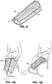
- FIG. 1 illustrates a modular heat therapy device for use with a heat therapy system.
- the system includes a modular heat transfer therapy apparatus, also referred to as a "wrap", which includes a first modular member or portion and a second modular member or portion.
- the first modular member or portion comprises a heat transfer device, and the second modular member portion forms a pouch into which the first modular member is placed.
- the first modular member can be readily removed so that one can clean either or both the first and second modular members and/or replace either of the first and second modular members.
- the second modular member can be constructed of material so that it is washable and reusable so that the second modular member can be cleaned after being stained with blood or otherwise soiled.
- the second modular member can be made so that it is a low-cost single-user disposable product.
- the ability to remove the first modular member from the second modular member and clean or replace the latter is especially advantageous when the apparatus is used on different patients. Further, one can replace the first or second modular member when portions thereof are beginning to fail after a long period of use. With this construction, a faulty heat exchanger can be easily replaced.
- the ability to replace one modular member also can avoid the need to dispose of the entire apparatus, thereby providing the ability to reduce cost over time.
- Modular heat transfer therapy apparatus 100 generally comprises first modular member 102 and second modular member 104, which forms a cover for the first modular member and in FIG. 1 is shown in the form of a sleeve.
- apparatus 100 is adapted to be wrapped around at least a portion of a patient's body and form a sleeve around that portion.
- first modular member 102 is inside the second modular member 104 and hidden from view.
- second modular member 104 comprises two compliant bladders, outer bladder 106 ( FIG. 2 ) and inner bladder 108 ( FIG. 3 ), which form separate chambers such as chambers 106a and 108a for different fluids.
- Compliant bladders 106 and 108 are generally parallel to one another (see FIG. 6 ) and are made so as to preclude fluid communication therebetween or between chambers 106a and 108a during use.
- Bladders 106 and 108 can be formed from three sheets of material with one forming a common inner wall for chambers 106a and 108a as will be described in more detail below.
- outer bladder 106 is adapted to receive a first fluid such as a gas (e.g., air), which can be regulated to provide the desired amount of inflation of the bladder or pressure therein. This inflation or pressure affects the compressive force applied to the animate body during use as will be further described below.
- Inner bladder 108 is adapted to receive a fluid, such as a coolant, which can be in the form of a cold liquid, to transfer heat away from the animate body part.
- the fluid supplied to inner bladder 108 can have a temperature higher than ambient so as to heat the animate body part. In the example illustrated in FIG.
- a three port manifold 110 provides a port for a fluid such as air to be introduced and exhausted from bladder 106 and fluid inlet and outlet ports for circulating fluid through bladder 108.
- Each port is formed by a tubular member, which has one end adapted to receive a hose connector as is known in the art and another end adapted to be inserted into one of three tubes (not shown) extending from the bladder (described below).
- each of the manifold fluid inlet and fluid outlet tubular members or passageways can be provided with a valve such as a spring loaded valve that is configured to allow the passage of fluid therethrough when the fluid hose connectors are coupled to the manifold and to prevent fluid flow therethrough when the fluid hose connectors are uncoupled from the manifold as is known in the art.
- a valve such as a spring loaded valve that is configured to allow the passage of fluid therethrough when the fluid hose connectors are coupled to the manifold and to prevent fluid flow therethrough when the fluid hose connectors are uncoupled from the manifold as is known in the art.
- fluid such as a liquid coolant is blocked from exiting fluid bladder 108 when the fluid hoses are uncoupled from the manifold.
- the gas port does not include a valve.
- the tubes extending from bladder 108 can be placed adjacent to the tube extending from bladder 106 with the tube for bladder 106 above and between the tubes for bladder 108.
- bladder 106 is formed with an opening and bladder 108 is formed with two openings to receive the tubes in the orientation described above.
- a tube, such as a polyurethane tube, is positioned in each one of these openings and then welded to a respective bladder to form a fluid tight seal therewith.
- the tubes extending from the bladders typically have an inner diameter of about 1/8-inch.
- the manifold passageways typically have a diameter of about 1/4- inch.
- Manifold 110 can be inserted into the tubes to form a seal therewith.
- each manifold tubular member end portion that mates with or is inserted into a respective tube extending from one or the other bladder can be provided with tapered hose barbs to enhance the seal as is well known in the art.
- a suitable manifold construction is disclosed in U.S. Pat. Nos. 5,104,158 and 5,052,725, both to Meyer, et al. and both entitled Two Piece Female Coupling.
- the manifold, which carries or forms the tubular members, can be configured to mate with the curves of the body when connected to the modular apparatus. It also can be provided with a ridge for finger placement to allow easier removal.
- a fluid circulation control unit as diagrammatically represented in FIG.
- reference numeral 180 is coupled to manifold 110 with tubing to fluidly communicate the therapy fluids to bladders 106 and 108 as will be described in more detail below. It should be understood that other manifold configurations and/or couplings to provide fluid flow between the fluid source and the bladders can be used as would be apparent to one of skill in the art. For example, valve need not be provided in the liquid port couplings.
- the illustrative heat transfer or heat exchange device includes compliant bladder 108, which circulates heat exchange fluid or liquid.
- This bladder is defined by a pair of generally parallel, flexible, or in other words, compliant, and fluid- or liquid-tight, walls or layers of material 152 and 154, which walls are sealed together by, for example, RF welding along their perimeters.
- Compliant gas pressure bladder 106 which overlays heat exchange bladder 108 as illustrated to direct gas (most simply, air) pressure against the heat exchange bladder 106 to press it towards the portion of the body being treated.
- This compliant gas pressure bladder 106 is also defined by a pair of generally parallel and flexible walls or layers of material 150 and 152.
- wall 152 is a common wall, i.e., one side of the same aids in defining gas pressure bladder 106 whereas the other side aids in defining bladder 108.
- wall or layer 150 is also secured to walls 152 and 154 via RF welding along its perimeter.
- connections in the interior of heat exchange liquid bladder 108 include a relatively uniform distribution of dot connections as shown in FIG. 3A and designated with reference character "D." This matrix of connections acts to disperse the liquid throughout the bladder. This dispersion is further aided by curvilinear fence connections provided for the purpose of directing the flow of a liquid. These fence connections are indicated by the reference numeral F in FIG. 3A . In the illustrative embodiment, the dots are formed in a triangular grid.
- sheets of material defining the walls 152 and 154 are RF welded together at the dot connections and at the interior fences.
- the wall 150 is RF welded to the other walls at the perimeter of the bladder. This RF welding will also form a common border for walls 150, 152, and 154.
- the heat transfer or heat exchange device is welded with each of the three layers having a rotated true grain of about 10-30° with respect to one another.
- This grain rotation can dramatically improve resistance to ripping of the heat exchanger.
- sheets 150, 152 and 154 have grain directions indicated with arrows "A,” "B” and "C,” respectively.
- Grain direction B of sheet 152 is offset in a counterclockwise direction from grain direction A of sheet 150 by about 30°.
- grain direction C of sheet 154 is offset in a clockwise direction from grain direction A of sheet 152 by about 30°.
- Each of the walls 150, 152 and 154 can be made of a nylon material suitably coated with polyurethane to provide both the RF welding qualities and the needed liquid or air impermeability.
- the heat transfer or heat exchange device can comprise fabrics (e.g., nylon fabric) that are laminated with asymmetric amounts of polyurethane. That is, the inner surface of the outer wall of the coolant chamber has an extra heavy coating, which corresponds to about a 5 oz coating of polyurethane, while the inner surfaces of the other walls have standard coatings corresponding to about 3 oz coatings of polyurethane. Accordingly, the surfaces of the inner wall of the coolant and air chambers and the inner surface of the outer wall of the air chamber have standard 3 oz coatings.
- the inner wall of the coolant chamber has a 5 oz coating of polyurethane in order to facilitate a yet stronger bond at the expense of increased manufacturing costs due to the use of a second non-standard fabric.
- a finish on the nylon material can also provide a permanent antimicrobial finish to prevent mold growth.
- Modular member 104 comprises an inner or front side portion 112 and an outer or back side portion 114.
- Member 104 can be made from various materials and can comprise inner and outer sheets of material that are sewn or fused together.
- the inner and outer sides can comprise two sheets of fabric, which are sewn together to form seam 116.
- An additional seam 118 is provided so that seams 116 and 118 form flap or marginal portion 120 and the perimeter of pouch 122, which is adapted to receive first modular member 102.
- Binding can be provided around the perimeter of second modular member 104 as shown in FIG. 6 .
- Outer back side portion 114 of second modular member has an opening 124 formed therein for receiving first modular member 102 as shown in FIG. 4 .
- a portion of back side 114, such as portion 126, can be pulled back ( FIG. 2 ) to facilitate positioning the remaining portion of first modular member 102 into the pouch.
- Numeral 114a indicates the inner surface of back side portion 114 and is shown in the inner surface portion 126.
- Any suitable fastening means can be used to close opening 124.
- zipper 127 can be provided along the sides of the opening.
- Second modular member 104 also includes a fastener for holding the apparatus in the desired location on the animate body. Accordingly, when the apparatus is wrapped around a portion of or the entire region being treated, the fastener holds the apparatus in place during treatment.
- a hook and loop fastener is used. It should be understood that if the hook and loop fastener wears out, the removable second modular member or sleeve can be readily replaced.
- the loop material portion 128 of the hook and loop fastener can be integrally formed with or placed over essentially all of outer back side portion 114 of second modular member 104.
- a strip of loop material can be integrally formed with or placed over a portion or the entire length (measured from the upper to lower edge of member 104 while referring to FIG. 2 ) of outer back side portion 114 along the side opposite flap 120.
- the hook material portion of the hook and loop fastener is shown in FIG. 3 and generally designated with reference numeral 130.
- Hook portion 130 can be in the form of a single strip that extends along the height of inner front side portion 112 (measured from the upper to lower edge, of inner front side portion 112) or it can be integrally formed with front side portion 112 in the same region. It can extend about 50% to 100% of the length of portion 112. Alternatively, hook portion can comprise a plurality of strips, which can be spaced along the length of portion 112.
- the active areas of the hook and loop fastener are outside the seams forming pouch 122.
- the forces may tend to resolve as shear forces as compared to other forces that can peel the hook portion from the loop portion.
- loop portion 128 is non-stretch material. What is meant by non-stretch material or non-stretchable material is material that stretches less than or equal to 3% of its length when held in tension under a load of no more than 10 pounds.
- the non-stretch loop portion can improve the efficacy of compression on the animate body when the apparatus is in place.
- Loop portion 128 can be made of non-stretch material, which can be woven or non-woven fabric.
- loop portion 128 can be made by securing loop material or fabric to non-stretch backing material, which can be woven or non-woven fabric.
- the non-stretch backing material for example, can be made of nylon or Tyvek.RTM.
- outer back side portion 114 can comprise first and second materials where the first material is non-stretch material (e.g., non-stretch woven or non-woven fabric), the second material is loop material and the non-stretch material forms backing for the loop material.
- first material is non-stretch material (e.g., non-stretch woven or non-woven fabric)
- second material is loop material
- non-stretch material forms backing for the loop material.
- the second modular member 104 or sleeve also can have a permanent antimicrobial finish to prevent mold growth, such as finishes made according to military specification MIL.STD.810D.
- the finish can be applied by placing the fabric in a chemical dip as is known in the art.
- the second modular member or sleeve can act as a blood barrier to prevent contamination of the heat exchanger and reduce transmission of bacteria from patient to patient.
- the inner faces of the second modular member that form the pouch and contact first modular member 102 can be nylon with a durable water repellency (DWR) coating, which is typically a 1/2 ounce polyurethane coating.
- DWR durable water repellency
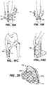
- FIG. 5A illustrates the modular portions of FIG. 4 with the first modular member inside second modular member 104 and zipper 127 closing opening 124.
- the apparatus is ready to apply to the portion of the body to be treated.
- the pouch that second modular member 104 forms allows first modular member 102 to float therein.
- This can provide a more evenly distributed compression around the gas bladder, resulting in improved therapy of the body being treated.
- the heat exchange device can move within pouch 122, there is less chance that a portion of the heat exchange device blocks coolant flow when the apparatus is improperly applied to the portion of the body being treated. For example, if an improper fold occurs in the heat exchange device, the heat exchange device may self-correct its position and relieve blockage of coolant flow.
- FIGS. 7A-C An exemplary use of modular therapy apparatus 100 will be made with reference to FIGS. 7A-C .
- apparatus 100 is positioned adjacent to a portion of a human patient's arm to be treated with the apparatus in an open state.
- Apparatus 100 which is coupled to fluid circulation and pressurizing unit 180, is then wrapped around the patient's arm and the second modular member hook portion 130 along flap 120 fastened to a portion of the loop portion of member 104.
- the control unit includes a mechanism for cooling and circulating a liquid coolant, which includes a reservoir for containing ice water.
- the liquid is normal tap water. This liquid was cooled by placing ice into the ice box portion of the control unit, resulting in temperatures ranging typically between 40° F. and 50° F.
- the control unit accepts liquid that has been returned from the heat exchange bladder 108. Before reintroducing the heat exchange liquid into bladder 108, it can be mixed with the liquid in the reservoir or it can be directed to bypass the reservoir. That is, the control unit is capable of supplying liquid at other controlled temperatures by means of mixing liquid chilled in the ice box and liquid warmed in the bladder by means of contact with an animate body and returning the mixed liquid to the bladder.
- the pressure of air furnished by the control unit is generally about 0.25 to 1.5 psig.
- the invention is applicable to many other types of therapy components, and the particular liquid, its temperature and pressure will be dependent upon the design and purpose of such therapy components. This is also true of the air pressure and in some instances it is cycled between two pressures (typically between 1.5 and 0.25 psig).
- the second modular member can have various shapes to accommodate different areas of an animate body. Typically, the area of one side of the second modular member will range from about 1 to 6 square ft. In the case of the knee application, this area will be about 6 square ft. In the case of an elbow, this area will be about 1 to 1.5 square ft.
- apparatus 100 has been described with a dual bladder heat exchange device, a single bladder heat exchange device can be used.
- the bladder is adapted circulate liquid or coolant.
- FIG. 5B illustrates one variation of FIG. 5A .
- the embodiment of FIG. 5B is the same at that shown in FIG. 5A with the exception that second modular member is modified (as indicated with reference numeral 104') so that the portion of the second modular member outside and to the left side of pouch 122 is larger. That portion is indicated with reference numeral 121 and typically will have a width of at least 1 inch a more specifically in the range of range of 1 to 12 inches. A further seam 118' also can be provided.
- the ability to enlarge the overall dimension of the second modular member, while maintaining the configuration and dimension of pouch 122 unchanged facilitates using a single heat exchange device with many differently sized second modular members or sleeves to treat differently sized patients or different body portions.
- another embodiment of the invention comprises a system for treatment of differently sized members.
- the system includes a plurality of differently sized second modular members each having a pouch 122 of the same configuration and size and a plurality of first modular members 102, each adapted to fit in any of the pouches or each being of the same size and configuration.
- the second modular member can be selected based on the animate body portion being treated and combined with any one of the heat exchange devices.
- Modular therapy apparatus 200 is the same as apparatus 100 with the exception that it is larger and its configuration is slightly modified so that it better adapted to from a sleeve around ones upper leg and knee as shown in FIGS. 9A and 9B .
- flap 220 which includes a hook portion that is hidden from view, is the same as flap 120 with the exception that it is larger and its configuration is slightly modified as shown in the drawings.
- FIGS. 10 and 11 another embodiment of the invention is shown and generally designated with reference numeral 300.
- apparatus 300 can be used, for example, to treat the core or torso of a human body.
- FIG. 10 illustrates bottom plan views of the modular portions of apparatus 300 and
- FIG. 11 illustrates top plan views of the modular portions of FIG. 10 .
- Apparatus 300 comprises first modular member 302 and second modular member 304.
- First modular member 302 includes gas bladder 306 and fluid or coolant bladder 308. Bladders 306 and 308 form chambers 306a and 308a, respectively.
- first modular member 3 02 is the same as first modular member 102 and can be made in the same manner, with the exception that a plurality of connections between the walls defining the modular member or air bladder 302 can be provided.
- a plurality of connections between the walls defining modular member or air bladder 302 can be provided as described in U.S. Pat. No. 6,695,872 to Elkins .
- Such connections can minimize or eliminate undesirable ballooning when the bladder is pressurized.
- the bladders are formed by RF welding (see e.g., FIG. 12 )
- this is simply achieved by forming some of the connections normally provided in liquid bladder 308, while sheet 350 is in place as will be described in more detail below.
- these connections are also formed in air bladder 306, that is, these connections are both within the liquid bladder and in the air bladder. It appears functionally as if the desired connections provided in the liquid bladder are "telegraphed" also to appear in the air bladder.
- the shape of gas pressure bladder 306 conforms to the shape of the heat exchange bladder 308.
- Fences or dividers in the heat exchange bladder to direct fluid flow can be also provided in the gas pressure bladder. These control fences are indicated by the reference numeral C in FIG. 12 . They can be provided in bladder 306 not only for the purpose of directing the flow of a liquid or gas, but also to secure the walls defining the gas pressure bladder together at various locations within the interior of such bladder. These connections provided by the fences C can prevent the gas bladder from "ballooning" out as described above and causing the temperature control liquid bladder not to conform to the body part. These fences register with the comparable fences in the liquid bladder.
- sheets of material defining the walls 352 and 354 are RF welded together at the dot connections and if desired, at the interior fences.
- the wall 350 is RF welded to the other walls at the perimeter of the bladder with any interior fences being formed as needed.
- Such fences C will thereby be formed in both bladders providing the desired liquid flow directors in the liquid bladder and the connections in the air bladder. This RF welding will also form a common border for walls 350, 352, and 354.
- the inner fences construction also can be provided in the gas bladder of the embodiment of FIGS. 20-24 , which is described in detail below.
- Second modular member 304 is the same as second modular member 104 with the exception that second modular member is differently configured and includes central portion 304a, and straps or strap portions 304b and 304c. Strap portions 304b and 304c are secured to central portion 304a as will be described in more detail below.
- Second modular member central portion 304a comprises an inner or front side portion 312 and an outer or back side portion 314. Central portion 304a can be made from various materials and can comprise inner and outer sheets of material that are sewn or fused together as previously described in connection with member 104 and can include seam 316 which defines the perimeter of pouch 322. Pouch 322 is adapted to receive first modular member 302. Strap portions 304b and 304c can comprise one or more layers of material. When more than one layer is used, the layers can be sewn or fused together as would be apparent to one skilled in the art.
- Outer back side portion 314 of central portion 304a has an opening 324 formed therein for receiving first modular member 302 as shown in FIG. 13A .
- Any suitable fastening means can be used to close opening 124.
- zipper 327 can be provided along the sides of the opening ( FIGS. 13B & C ).
- Second modular member 304 also includes a fastener for holding the apparatus in the desired location on the animate body. Accordingly, when the apparatus is wrapped around a portion of or the entire region being treated, the fastener holds the apparatus in place during treatment. As in the embodiments described above, a hook and loop fastener is be used in this illustrative embodiment.
- the loop material portion 328 of the hook and loop fastener can be integrally formed with or placed over essentially all of outer back side portion 314 of second modular member 304. Therefore, the loop material portion can cover the outer back side surface of center portion 304a, and strap portions 304b and 304c ( FIG. 11 ).
- a strip of loop material can be integrally formed with or placed over a portion or the entire length (measured from the upper to lower edge of member 304) adjacent the outer end of portion 304c and along interface with center portion 304a.
- loop portion 328 is non-stretch material and can be made in the same manner as loop portion 128 as described above.
- hook material portion of the hook and loop fastener that fastens the apparatus to the animate body is shown in FIG. 10 and generally designated with reference numeral 330.
- Hook portion 330 is positioned on the front side portion 312 of strap 304b and can be in the form of a single strip that extends along the outer end portion of strap 304b or it can be integrally formed with the front side portion of 304b. It can extend about 50% to 100% of the length of strap 304b. Alternatively, hook portion can comprise a plurality of strips, which can be spaced from one another. Hook material portions 330 also are provided along the inner end portions of straps 304b and 304c. These portions are shown in dashed line in FIG. 10 .
- the active areas of the hook and loop fastener on the outer end portions straps 304b and 304c are outside the seam forming pouch 122.
- the hook and loop fastener that operates between the inner end portions of strap portions 304b and 304c and center portion 304a facilitate removal of the strap portions. This, in turn, facilitates replacement of either or both straps or repositioning of the straps.
- the straps can be portioned as shown in FIG. 13B , which may be preferred when treating the upper torso of a patient.
- the straps can be removed and repositioned as shown in FIG. 13C , which may be preferred when treating the lower portion of the patient's torso.
- FIGS. 14A-D diagrammatically depict use of the apparatus 300 where FIG. 14A show a first step in wrapping the apparatus around the waist or lower portion of the torso of a patient, FIG. 14B shows securing the apparatus in place, and FIG. 14C shows the apparatus being in its final position and ready for use.
- FIG. 14D shows the apparatus with the straps repositioned and the apparatus being wrapped around the upper torso of the patient.
- Modular therapy apparatus 400 can be used, for example, to treat an ankle and/or foot of a patient.
- FIG. 16 illustrates top plan views of modular portions of apparatus 400 and
- FIG. 17 illustrates bottom views of the modular portions of apparatus 400.
- Apparatus 400 comprises first modular member 402 and second modular member 404.
- First modular member 402 includes gas bladder 406 and fluid or coolant bladder 408. Bladders 406 and 408 form chambers 406a and 408a, respectively. Except for the configuration of first modular member 402, first modular member 402 is the same as first modular member 102 and can be made in the same manner.
- Second modular member 404 is the same as second modular member 104 with the exception that second modular member is differently configured, has differently positioned hook portions and has heel alignment marker 405. Accordingly, member 404 can be made from various materials and can comprise inner and outer sheets of material that are sewn or fused together as previously described in connection with member 104 and can include seam 416, which in combination with seams 418, defines the perimeter of pouch 422. Pouch 422 is adapted to receive first modular member 402.
- Outer back side portion 414 has an opening 424 formed therein for receiving first modular member 402 as shown in FIG. 16 .
- Zipper 427 can be provided along the sides of the opening ( FIG. 18C ).
- Second modular member 404 also includes a fastener for holding the apparatus in the desired location on the animate body and can include the hook and loop fastener system described in connection with apparatus 100.
- the loop material portion 428 of the hook and loop fastener can be integrally formed with or placed over essentially all of outer back side portion 414 of second modular member 404.
- a strip of loop material can be integrally formed with or placed over a portion of back side portion 414 that would cooperate with the hook portions in accordance with FIGS. 17 and 19A-C .
- loop portion 428 is non-stretch material and can be made in the same manner as loop portion 128 as described above.
- hook material portion of the hook and loop fastener that fastens the apparatus to the animate body is shown in FIG. 17 and generally designated with reference numeral 430.
- Hook portions 430 can have a width of about 4 inches.
- the active areas of the hook and loop fastener are outside the seams forming pouch 422, which can provide similar advantages to those described above regarding force resolution when the apparatus is under compression.
- FIGS. 18A-C illustrate inserting the modular member 402 into modular member 404.
- FIG. 18A illustrates a first stage of inserting modular member 402 into modular member 404.
- FIG. 18B illustrates another stage portion into the other and
- FIG. 18C illustrates member 402 fully inserted and zipper 327 closed.
- FIGS. 19A-D illustrate use of the embodiment of FIG. 10 .
- FIG. 20 another embodiment of the invention is shown and generally designated with reference numeral 500.
- Apparatus 500 can be used to treat the shoulder of a patient.
- FIG. 21 illustrates top views of the modular members of the apparatus 500 and
- FIG. 22 illustrates bottom views of the modular members shown in FIG. 21 .
- Apparatus 500 comprises first modular member 502 and second modular member 504.
- First modular member 502 includes gas bladder 506 and fluid or coolant bladder 508.
- Bladders 506 and 508 form chambers 506a and 508a, respectively.
- First modular member 502 is the same as first modular member 102 except for the configuration of modular member 502, including flap portions 562, and that it can include the inner fence construction described above in connection with the embodiment of FIGS. 10-14 .
- Modular member 502 also differs from modular member 102 in that it includes a coupling mechanism for coupling these flap portions. More specifically, flap portions 562 are coupled to one another through elastic cord 560, which is laced through holes formed in first modular member 502. The elastic cord substantially maintains flaps 562 in the closed position shown in FIG. 21 when bladder 506 is inflated and fluid circulated through bladder 508.
- Second modular member 504 is the same as second modular member 104 with the exception that second modular member is differently configured and includes central portion 504a, and straps or strap portions 504b, 504c, and 504d. Strap portions 504b, c & d are secured to central portion 504a as will be described in more detail below.
- Second modular member central portion 504a comprises an inner or front side portion 512 and an outer or back side portion 514.
- the arm sling 540 can be coupled to second modular member 504 through a plurality of snap connectors "S" or any other suitable connector including but not limited to hook and loop fasteners.
- Central portion 504a can be made from various materials and can comprise inner and outer sheets of material that are sewn or fused together as previously described in connection with member 104 and can include seam 516, which in combination seam 518, define the perimeter of pouch 522.
- Pouch 522 is adapted to receive first modular member 502.
- Strap portions 504b, c, and d can comprise one or more layers of material. When more than one layer is used, the layers can be sewn or fused together as would be apparent to one skilled in the art.
- Outer back side portion 514 has an opening 524 formed therein for receiving first modular member 502 as shown in FIG. 16 .
- Zipper 527 can be provided along the sides of the opening ( FIG. 18C ).
- Second modular member 504 also includes a fastener for holding the apparatus in the desired location on the animate body and can include the hook and loop fastener system described in connection with apparatus 100.
- the loop material portion 528 of the hook and loop fastener can be integrally formed with or placed over essentially all of outer back side portion 514 of second modular member 504.
- a strip of loop material can be integrally formed with or placed over a portion of back side portion 514 that would cooperate with the hook portions described below.
- loop portion 528 is non-stretch material and can be made in the same manner as loop portion 128 as described above.
- the hook material portion of the hook and loop fastener that fastens the apparatus to the animate body and generally designated with reference numeral 530.
- the hook portion of strap portion 504b can comprise two sections, each having a length extending along the length of the strap of about 4 or 5 inches. These sections can be spaced apart by about 1 inch to facilitate or improve flexibility of the end portion of the strap. In this manner, the strap can be readily folded to provide length adjustment for differently sized users.
- the active areas of the hook portion of the hook and loop fastener are outside the seams forming pouch 522, which can provide similar advantages to those described above regarding force resolution when the apparatus is under compression.
- FIGS. 23A-D illustrate coupling the modular members 502 and 504 where FIG. 23A illustrates aligning modular member 502 with opening 524 in second modular member outer back side portion 514.
- FIGS. 23B and C show insertion of modular member 502 into modular member 504 and
- FIG. 24D shows back side portion 514 closed and zipped up.
- FIGS. 24A-D diagrammatically illustrate use of apparatus 500 where FIG. 24A shows a first stage in pulling the apparatus over the patient's arm and toward the patient's shoulder.
- FIG. 24B illustrates positioning the apparatus over the shoulder of the patient and securing hook portions of straps 504c and 504d to portions of central portion 504a which are constructed with loop material to secure apparatus 500 to the patient's arm. Strap 504b is then pulled under the patient's other shoulder and a portion of its hook portion is ready to be fastened to the loop material of central portion 504a ( FIG. 24C ).
- the end portion of strap 504b is folded back along the space between hook portions 530 and secured in that position by tucking into a pocket designed to accept it.
- FIG. 24D also shows optional strap 640, which can be used to hold up the lower arm of the patient.
- Strap 540 can have a hook portion on one end and snaps at the opposite end so that the hook portion can be fastened to loop material the outer side portion 514 or second modular member 504 and the snaps can be fastened to the snaps on modular portion 504.
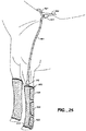
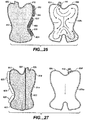
- FIG. 25 a further embodiment of the invention is shown and generally designated with reference numeral 600.
- Apparatus 600 is especially suited for equine applications.
- apparatus 600 is shown wrapped around at horse's leg.
- the therapy fluids are delivered though the hose 601, which has one end coupled to apparatus 600 through manifold 110 and its other end coupled to a therapy fluid circulation control unit such as control unit 160.
- conduit 601 can have three channels for fluid flow (e.g., two for liquid or gas coolant and one for gas).
- conduit 601 is directly fluidly coupled to a fluid circulation control unit.
- a Y-connector can be provided as shown in FIG. 25 .
- conduit 605 fluidly couples the Y-connector 603 with the circulation control unit (not shown).
- the Y-connector facilitates fluidly coupling each conduit 601, which is fluidly coupled to a respective apparatus 600 through a manifold 110, to the circulation control unit so that a plurality of legs (i.e., 2) can be treated at the same time.
- FIG. 26 illustrates bottom plan views of modular portions of apparatus 600 and FIG. 17 illustrates top views of the modular portions of apparatus 600.
- Apparatus 600 comprises first modular member 602 and second modular member 604.
- First modular member 602 includes gas bladder 606 and fluid or coolant bladder 608.
- Bladders 606 and 608 form chambers 606a and 608a, respectively.
- first modular member 602 is the same as first modular member 102 and can be made in the same manner.
- Second modular member 604 is the same as second modular member 104 with the exception that second modular member is differently configured including differently configured hook portions 630. Accordingly, member 604 can be made from various materials and can comprise inner and outer sheets of material that are sewn or fused together as previously described in connection with member 104 and can include seam 616, which defines the perimeter of pouch 622. Pouch 622 is adapted to receive first modular member 602. Inner side portion 612 is placed against the portion of the body being treated and outer back side portion 614 has an opening formed therein for receiving first modular member 602. The opening is shown closed with zipper 627 in FIG. 27 .
- Second modular member 604 also includes a fastener for holding the apparatus in the desired location on the animate body and can include the hook and loop fastener system described in connection with apparatus 100.
- the loop material portion 628 of the hook and loop fastener can be integrally formed with or placed over essentially all of outer back side portion 614 of second modular member 604. Alternatively, it can be integrally formed with or placed over the right portion of zipper 627 or the side of zipper 627 opposite flaps 620.
- loop portion 628 is non-stretch material and can be made in the same manner as loop portion 128 as described above.
- hook material portion(s) of the hook and loop fastener that fastens the apparatus to the animate body is shown in FIG. 26 and generally designated with reference numeral 630.
- Hook portions are integrally formed with or secured to flaps 620, which extend outward form seam 618.
- Hook portions 630 are can have a width of about 3 inches and a length of about 12 to 30 inches.
- any of apparatus 200, 300, 400, 500, and 600 can be provided with differently sized second modular members, but with same sized pouches and same sized first modular members to facilitate component interchangeability in a manner similar to that described in connection with FIG. 5B .
- a therapy wrap in accordance with various aspects of the invention includes a variable insulating layer.
- "Variable insulating” generally refers to providing an insulating element in targeted locations and/or providing a variable thermal resistivity along the wrap.
- the insulating layer may improve the performance of the wrap by, among other things, compensating for the temperature delta and protecting the body part in selected areas.
- the insulating layer may also serve to reduce the temperature delta by insulating a portion of the flowpath from heat loss.
- the illustrated apparatus is a therapy wrap, generally designated 800a, for providing temperature-controlled therapy to an anatomical body part.
- wrap 800a Various aspects of wrap 800a are similar to the apparatus described above.
- the body is a mammalian body, and preferably a human body.
- the wrap may be used on a knee, an elbow, a shoulder, a leg, and arm, and more.
- Wrap 800a includes a fluid bladder 808 and one or more thermal insulating members 880.
- the fluid bladder includes an inlet 860 and outlet 862.
- a heat exchanging fluid from a reservoir is introduced to the bladder through the inlet, typically using a pump.
- Exemplary outlet 862 is connected to the reservoir so fluid is returned and recirculated.
- the insulating members are attached to one side of the fluid bladder.
- Fluid bladder 808 is configured and constructed similar to fluid bladder 108 described above and shown in FIGs. 3 , 6 , and 12 , and includes one or more fluidic channels 865 connecting the inlet and the outlet. As described above and shown, for example, in FIGs. 3 and 3A , the fluid flowpath may be defined by a number of walls, fences, and the like.
- FIG. 28 illustrates the overlay of insulating members 880 and fluid bladder 808.
- the exemplary wrap includes two regions with insulating members 880.
- a first region is in the inlet area (colder fluid) adjacent inlet 860 and includes heavier insulation.
- a second region is positioned near the outlet area (warmer fluid) near the warmer return fluid channel leading to outlet 862 and does not include any insulation.
- the wrap includes medium insulation-less than the first region.
- the insulating member in the first region (inlet) is thicker, thereby reducing the heat transfer rate in that region.
- the insulating members when the insulating members are affixed to the bladder, the insulating members are positioned along fluidic channel 865, and consequently the fluid flowpath.
- the insulating members are generally positioned in regions lying within the respective fluidic channels.
- the insulating members are separated from each other.
- two or more insulating members are contiguous but separate elements.
- Fluid channel is to be understood as generally used in the art.
- “fluidic channel” refers to the fluid pathway defined by the walls, fences, weld lines, dots, and the like.
- the channel width is generally designated “W”.
- “Fluidic channel” may refer to the entire pathway from wall-to-wall or a space in between in a width direction.
- the channel width may extend from a wall to a region between the walls, designated W', or entirely within a space between the walls, designated W".
- each of the insulating members are dimensioned to correspond to a respective one or more fluidic channels.
- the insulating members are positioned in a pattern corresponding to a flowpath defined by one or more fluidic channels.
- the illustrated wrap includes a serpentine shaped flowpath and the insulating members have a corresponding pattern.
- the exemplary insulating members are positioned entirely within the width of the fluidic channel.
- the wrap may also include one or more insulating members positioned independently of the fluidic channels.
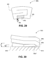
- FIG. 29 illustrates another wrap 800b having a single insulating member 880b positioned directly adjacent inlet 860 and extending along a fluidic channel 865 from the inlet.
- the exemplary insulating member is contiguous with the inlet along one edge and extends into the fluidic channel at an opposite end.
- the wrap including the insulating members is used in a similar manner to the wrap and therapy systems described above.
- a user applies the wrap similar to the non-variable insulating wrap shown, for example, at least in FIGs. 7C , 9B , 14D , 15 , 24D , and 25 .
- the wrap is connected to a reservoir, pump, and other system components.
- the user turns on the system to flow fluid to the wrap for therapy.
- the fluid is returned to the reservoir from the wrap outlet and recirculated.
- the variable insulating wrap allows for greater flexibility and improved performance.
- the lowest temperature of the fluid is generally at the inlet where the fluid from the reservoir first enters the bladder.
- the fluid starts to warm as it exchanges (receives) heat from the body part.
- the insulating member extends downstream from the inlet, a key feature of the exemplary insulating member is the fact that the insulating member starts at the inlet where the fluid is coldest. Accordingly, the insulating member provides an insulating effect in the region where the fluid is coldest. This provides several benefits. For one, the body part is thermally shielded from the fluid in the region of the lowest temperature. This reduces the likelihood of frost bite or cold burn. Second, the insulating member generally increases patient comfort.
- the temperature delta in the wrap may be large, the heat exchange in the inlet region is generally reduced, essentially equilibrating or normalizing the heat transfer. In turn, the "feel" of the wrap is more comfortable in the inlet region. Alternatively, the inlet temperature may be decreased while maintaining the same "feel" in the inlet region for the user. In various aspects, the variable insulating layer compensates for the temperature delta such that the surface temperature is consistent or at least "feels" consistent to the user.
- Insulating member 880 may be modified and varied using conventional techniques as would be understood from the description herein.
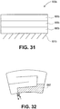
- FIGs. 30 and 31 illustrate cross-sections of exemplary insulating members 880 and generally correspond to the wrap of FIG. 29 .
- the exemplary wrap 800a includes fluid bladder 808, one or more insulating members 880, and an expandable air bladder 806 for applying a compressive force.
- the wrap is shown in the treatment position adjacent a body part 801.
- the insulating effect of the insulating member is modified by adjusting the thickness of the respective members.
- a first insulating member 880b' has a maximum thickness t 1 and tapers to a thickness t 2 .
- a second insulating member 880b" has substantially uniform thickness.
- the thickness in the second region is essentially the same as the minimum thickness of the first region, namely, t 2 .
- the bladder has little or no insulating member. All things otherwise being the same, the overall coefficient of heat transfer is reduced moving from the first region to the third region. In other words, the rate of heat transfer in the first region will be slower than the rate of heat transfer in the second region.
- the insulating members may be modified in other ways such as by stacking layers of material to increase the thickness.
- Suitable materials for the insulating member include, but are not limited to, a foam, a plastic, a fibrous material, and other insulating materials known in the art.
- the insulating member may be composed of a fabric, spray-on rubber (e.g., poly(urethane)), glass fibers, and more.
- the insulating member may also include structures and configurations for controlled insulating effect.
- a housing may be provided that encloses a defined volume of gas (e.g. air) of a known thermal resistance.
- the insulating member may comprise a bladder filled with a thermo-resistive gel with a predetermined thermal resistance value.
- the insulating member is configured and selected to compensate for a temperature delta in the wrap and/or fluid temperature in the respective portion of the fluid channel.
- the insulating member is configured or selected to have a predetermined overall coefficient of heat transfer.
- the insulating member may be selected based on the material properties including, but not limited to, thermal resistance (R-value). Generally, the material properties, dimensions, and configuration are adjusted to provide the desired insulating of the wrap at the desired location and/or a variable amount of insulating.
- FIG. 31 illustrates an exemplary wrap including a single structure 880' in lieu of multiple insulating members 880.
- the structure 880' is composed of different materials having different coefficients of heat transfer.
- the structure of FIG. 31 thus includes a monolithic element that mimics the multiple insulating members with zones of varying thermal resistivity. In this way, the structure provides different overall heat transfer rates in different locations in spite of the generally uniform thickness and structure.
- the wrap may include two or more separate but adjacent insulating members of equal thickness but different coefficients of heat transfer to achieve the desired variable insulating effect.
- FIG. 32 illustrates a wrap with an insulating member 880 extending further in the axial direction away from the inlet. In use, the patient would generally be subjected to a lower maximum cold temperature.
- the wraps of FIGs. 33-35 include the insulating member of FIG. 32 and additional insulating members 880' and 880".
- an insulating member 880" is provided at an edge of the wrap opposite inlet 860 and outlet 862.
- a third insulating member 880'" is provided adjacent the outlet.
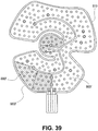
- the wrap of FIG. 35 includes insulating members 880, 880', and 880". Insulating member 880" extends along a fluidic channel between the inlet and outlet and has a diamond-shape. In the exemplary wrap, 880" provides thermal insulation in an area where therapy is not desirable either for medical or patient-controlled reasons.
- the location of member 880" may correspond to a bone area on the body part or an area where there is no tissue to be treated.
- the patient may have a "tender” area or some other reason for desiring greater thermal insulation in a particular spot.
- the insulating members are generally shown as being polygonal, one will appreciate that other shapes may be utilized.
- variable insulating wrap The method of making and assembling the variable insulating wrap above will now be described.
- the wrap may be manufactured using the techniques described above and known in the art in accordance with the description herein.
- FIG. 36 illustrates a cross-section of a wrap 800c similar to wrap 800b of FIG. 29 .
- the exemplary wrap includes an inlet, outlet, and additional port on a top side, one will appreciate that the location and configuration of the ports can be modified.
- the ports can be provided at one end of the sleeve in a vertical arrangement corresponding to the arrangement of the fluid bladder and compression bladder.
- the wrap includes a bladder 808c and compression bladder 806c.
- Bladder 808c and compression bladder 806c are fitted within a sleeve body 872.
- the sleeve includes a connector 867 for quick and easy connection of fluid inlet 860c, fluid outlet 862c, and a port 870 to compression bladder 806c.
- the sleeve is similar in many respects to temperature therapy pads described above.
- the illustrated sleeve is composed of nylon on one side and a loop material (e.g. pile) on an opposite side.
- an insulating layer 880c' is positioned on the bladder. In a thickness direction, the insulating layer is sandwiched between the fluid bladder 808c and an inner surface of sleeve body 872. On an opposite side, the compression bladder is sandwiched between the fluid bladder and the sleeve body.
- the exemplary insulating layer includes a substrate 874c supporting an insulating member 880c.
- the substrate and insulating member may be joined together permanently, removable, or otherwise separate.
- the substrate dimensions correspond to the bladder periphery.
- the substrate is dimensioned to be applied over the bladder whereby the insulation member aligns with the desired fluidic channels.
- the substrate and bladder fit snugly within the sleeve 872.
- the illustrated wrap is thus assembled by inserting insulating layer 880c' into the sleeve 872 adjacent the bladder 808c.
- the insulating member is bonded to the bladder with an adhesive.
- the insulation member may be attached to the bladder in other manner. In some cases, the insulation is not attached to the bladder at all.
- the sleeve may be elastomeric with an abrasive inner surface such that the insulation member is held in a desired location with respect to the bladder without bonding and the like.
- the one or more insulating members are integrally formed in insulating layer 880c'.
- the insulating layer is monolithically formed in essentially one step.
- the insulating layer may be formed by blow molding whereby the insulating members are formed essentially simultaneously.
- the insulating members may also be separately formed and thereafter joined to the substrate, Similarly, the insulating layer and/or insulating member may be formed concurrently with the bladder.
- Other manufacturing techniques include, but are not limited to, spraying, molding, silk screening, and adhesives.
- manufacturing techniques common in the polymer and semiconductor fields may also be used such as etching, deposition, and lithography. Further details regarding the components and manufacturing techniques that may be used are disclosed in U.S. Patent No. 7,198,093 to Elkins .
- FIGs. 37A, 37B, and 38 illustrate another wrap configuration whereby an insulating sleeve 872d is configured to receive a bladder 808d in a pocket 820.
- Pocket 820 is similar in some respects to pouch 122 and the openings described above and shown in FIGs. 1-4 .
- sleeve 872d includes integrated insulating members 880d.
- the wrap 800d is assembled by inserting the bladder into the sleeve 872d.
- the sleeve, sleeve pocket, and bladder have corresponding shapes and dimensions such that the bladder is automatically aligned in the sleeve when inserted into the pocket.
- the wrap 800e may include another insulating member 880e positioned in a desired location on the wrap.
- the wrap is customized based on a user's preferences.
- the location of the insulating member 880e does not necessarily correspond to a fluidic channel location 865e (shown in FIG. 37B ). Rather, the location of insulating member 880e corresponds to a location where a user does not want therapy.
- a bladder 808e having a desired variable insulating member pattern into the insulating sleeve.
- the insulating members may be formed and attached to the sleeve using techniques similar to those described above and shown at least in FIGs. 4 , 10 , 13A , 16 , and 23B .
- the wrap is assembled by providing a plurality of insulating sleeves, each with a pouch adapted to receive a bladder, selecting one of the insulating sleeves, and inserting the bladder into the sleeve.
- the plurality of sleeves may be dimensioned the same but include different insulating member patterns,
- a user may select a desired sleeve based on the variable insulating member pattern and then assemble the wrap by inserting a standard bladder.
- the user may further customize the wrap by inserting, removing, and/or modifying insulating members.
- the bladder may be configured to receive a selected one of a set of insulating layers having one or more insulating members.
- FIG. 39 illustrates another wrap formed by applying an insulating layer 880f' having a number of insulating members 880f to a fluid pad 810.
- the fluid pad is a conventional pad similar in various respects to the pad described in U.S. Patent No. 6,117,164 to Gildersleeve et al.
- pad 810 is designed to carry a heat exchanging fluid only.
- the pad does not include a compression device for applying a compressive force. Instead, the device is coupled to the body part with a hook and loop fastener.
- the exemplary fluid pad is a designed to fit over a knee or shoulder.
- the pad includes a fluidic channel 865f for promoting a desired flow even during joint flexure.
- the fluid channel and pad are dimensioned and configured to provide kink resistance during flexure.
- pad 810 includes a central portion intended to be positioned over a joint.
- the exemplary wrap includes two insulating members in the central region. Thus, the cooling is isolated to the tissue around the joint bone.
- the insulating layer may be a separately-formed, independent member for use with a variety of temperature-controlled therapy systems in accordance with the invention.
Landscapes
- Health & Medical Sciences (AREA)
- Engineering & Computer Science (AREA)
- Biomedical Technology (AREA)
- Heart & Thoracic Surgery (AREA)
- Vascular Medicine (AREA)
- Life Sciences & Earth Sciences (AREA)
- Animal Behavior & Ethology (AREA)
- General Health & Medical Sciences (AREA)
- Public Health (AREA)
- Veterinary Medicine (AREA)
- Physics & Mathematics (AREA)
- Thermal Sciences (AREA)
- Thermotherapy And Cooling Therapy Devices (AREA)
- Infusion, Injection, And Reservoir Apparatuses (AREA)
- Massaging Devices (AREA)
Description
- This application claims priority to
U.S. Provisional Application No.61/254,064 filed on October 22, 2009 - The present invention relates generally to therapy of an animate body, and more particularly a therapeutic wrap of the type having circulating fluid to provide cooling, heating, and/or compression to a human or animal body part.
- It is now common to apply cold and compression to a traumatized area of a human body to facilitate healing and prevent unwanted consequences of the trauma. In fact, the acronym RICE (Rest, Ice, Compression and Elevation) is now used by many.
- Cold packing with ice bags or the like traditionally has been used to provide deep core cooling of a body part. Elastic wraps are often applied to provide compression.
- It will be appreciated that these traditional techniques are quite uncontrollable. For example, the temperature of an ice pack will, of course, change when the ice melts, and it has been shown that the application of elastic wraps and, consequently, the pressure provided by the same, varies considerably even when the wrappers are experienced individuals.
- Because of these and other difficulties, many in the field have turned to a more complicated animate body heat exchanger. Most effective animate body heat exchangers typically include two major components, an external compliant therapy component covering a body part to be subjected to heat exchange, and a control component for producing a flowing heat exchange liquid. Many control units also produce and supply an air or other gas pressure needed to apply pressure to a body part and to press the heat exchange liquid toward such body part. This air pressure is directed to another compliant bladder of the therapy component, which air pressure bladder overlays the liquid bladder to press such liquid bladder against the body part to be subjected to heat exchange, as well as apply compression to the body part to reduce edema.
- As can be seen, a commonly used external therapy component uses a pair of compliant bladders to contain fluids; that is, it preferably has both a compliant bladder for containing a circulating heat exchange liquid and a gas pressure bladder which overlays the liquid bladder for inhibiting edema and for pressing the liquid bladder against the body part to be subjected to heat exchange.
- In general, the body heat exchanging component(s) of such an apparatus has a pair of layers defining a flexible bladder through which a liquid is circulated. This component is often referred to as a "wrap." The liquid fed to the wrap is maintained at a desired temperature. Generally, the desired temperature is lower than the temperature expected for the body part, and typically is achieved, at least in part, by passing the liquid through a heat exchanging medium, such as by passing the same through an ice bath, or a refrigeration unit. One such system is disclosed, for example, in
U.S. Pat. No. 6,178,562 . Other examples of therapeutic wraps are disclosed inUS5086771 ,US5662695 orUS6352550 . - One issue with these types of therapeutic wraps is that the fluid warms from the body part heat as it passes through the wrap. Accordingly, the average temperature fluctuates and the amount of heat transfer is inconsistent. In some cases, the fluid warms to a degree that a portion of the wrap no longer provides therapy. To counteract this effect, the flow rate can be increased or the fluid can be cooled to a lower temperature. Increasing the flow rate reduces the cooling effect of the wrap. Lowering the inlet temperature leads to very low temperatures in the inlet area of the wrap. If the temperature is too low, the wrap becomes uncomfortable for the patient and can even lead to burns during extended periods of use.
- There is a need for a wrap that provides efficient heat transfer over all of the treatment surface. There is a need for a wrap that provides efficient heat transfer while reducing the need to significantly increase or decrease the fluid temperature from the reservoir. There is the need to provide a wrap that improves patient comfort and/or reduces risks of injury to the body part treated.
- There remains a need to provide improved temperature-controlled therapy apparatus and methods for their use.
- The present invention involves improvements in heat transfer therapy apparatus and avoids disadvantages in the prior art.
- The present invention provides a therapy wrap according to claim 1.
- In various embodiments, the wrap includes another thermal insulating member on the fluid bladder extending along the at least one fluidic channel and separated from the thermal insulating member.
- The insulating member and the another insulating member may be modified to achieve the desired variation in insulating effect. In various embodiments, the insulating member is configured to decrease the rate of heat transfer by a greater degree than the another thermal insulating member. In various embodiments, the insulating member and the another insulating member have different coefficients of heat transfer. In various embodiments, the insulating member and the another insulating member have essentially equal thickness.
- In various embodiments, the insulating member and the another insulating member are contiguous. The insulating member and the another insulating member may be integrally formed in an insulating layer. The insulating member and the another insulating member may be monolithically formed as the insulating layer.
- In various embodiments, the wrap includes an expandable bladder on a side of the bladder opposite the insulating member for exerting a compressive force on the bladder.
- Various embodiments of the invention are directed to a therapy wrap including a fluid bladder including an inlet, an outlet, and at least one fluidic channel connecting the inlet to the outlet; and a thermal insulating layer affixed to the fluid bladder and having a shape dimensioned and configured to correspond to a perimeter of the bladder, the thermal insulating layer comprising a thermal insulating member extending along the at least one fluidic channel and positioned only directly adjacent the inlet when the layer is affixed to the bladder.
- In various embodiments, the thermal insulating layer further comprises another insulating member extending along the at least one fluidic channel and separated from the thermal insulating member. The insulating member and the another insulating member maybe contiguous. In various embodiments, the insulating member and the another insulating members are monolithically formed in the insulating layer.
- In various embodiments, the insulating layer is printed. In various embodiments, the insulating layer is bonded to the bladder. In various embodiments, the wrap includes a pocket for removably securing the insulating layer.
- In various embodiments, the at least one fluidic channel has a serpentine shape, and the insulating member and the another insulating member are positioned in a pattern corresponding to the at least one fluidic channel. In various embodiments, the at least one fluidic channel extends from wall-to-wall in a width direction.
- Also described is a method of administering a temperature-controlled treatment to an anatomical body part. The method includes applying a therapy wrap to an anatomical body part, the wrap including an inlet; an outlet; at least one fluidic channel connecting the inlet and the outlet; and a thermal insulating layer between the wrap and the body part extending along a flowpath of the at least one fluidic channel in a first
region only directly adjacent the inlet; flowing a heat exchanging fluid from a reservoir through the inlet to the at least one fluidic channel; and returning the fluid to the reservoir from the outlet. - In various procedure, the method includes flowing the fluid through a second region downstream from the first region, wherein an overall coefficient of heat transfer in the second region is more than an overall coefficient of heat transfer in the first region.
- In various procedures, the method includes decreasing the thickness of the insulating layer downstream from the first region to compensate for a temperature delta in the at least one fluidic channel.
- The wrap of the present invention has other features and advantages which will be apparent from or are set forth in more detail in the accompanying drawings, which are incorporated in and form a part of this specification, and the following Detailed Description of the Invention, which together serve to explain the principles of the present invention.
-
-
FIG. 1 is a perspective view of one embodiment of the invention; -
FIG. 2 illustrates top plan views of modular portions of the embodiment ofFIG. 1 ; -
FIG. 3 illustrates bottom plan views of the modular portions ofFIG. 2 ; -
FIG. 3A is an enlarged section of a portion of one of the modular portions ofFIG. 3 illustrating a dot connection pattern; -
FIG. 4 illustrates coupling the modular portions ofFIG. 2 ; -
FIG. 5A illustrates the modular portions ofFIG. 4 with one modular portion enclosed in a pouch in the other or outer modular portion; -
FIG. 5B illustrates a variation ofFIG. 5A where the inner enclosed portion has the same dimension and the out modular portion, which encloses the inner modular portion, is larger; -
FIG. 6 is a sectional view taken along line 6-6 inFIG. 5A ; -
FIGS. 6A and 6B diagrammatically illustrate the true grain orientation of the heat transfer device layers illustrated inFIG. 6 in accordance with one embodiment of the invention; -
FIGS. 7A-C illustrate use of the embodiment ofFIG. 1 , whereFIG. 7A illustrates applying the apparatus to the arm of a human user;FIG. 7B illustrates the apparatus wrapped around the arm; andFIG. 7C illustrates the apparatus wrapped around the lower portion or calf of the user; -
FIG. 8 illustrates another embodiment of the invention; -
FIGS. 9A-B illustrate use of the embodiment ofFIG. 8 , whereFIG. 9A illustrates the apparatus being wrapped around a human patient's upper leg and knee andFIG. 9B illustrates the apparatus fully wrapped around that region and ready for use; -
FIG. 10 illustrates bottom plan views of modular portions of another embodiment of the invention which, for example, is suitable for coupling to the patient's body core region; -
FIG. 11 illustrates top plan views of the modular portions ofFIG. 10 ; -
FIG. 12 is a sectional view of the embodiment ofFIG. 10 with the modular portions coupled; -
FIG. 13A illustrates coupling of the modular portions so that one modular portion is enclosed in a pouch in the other or outer modular portion; -
FIGS. 13B and 13C show two positions of the embodiment ofFIG. 10 after insertion of the one modular portion as shown inFIG. 13A , whereinFIG. 13B shows the belt or strap portions arranged downward andFIG. 13C show the belt or strap portions arranged upward; -
FIGS. 14A-D diagrammatically depict use of the embodiment ofFIG. 10 whereFIG. 14A show a first step in wrapping the apparatus around the waist of a patient,FIG. 14B shows securing the apparatus in place,FIG. 14C shows the apparatus being in its final position and ready for use, andFIG. 14D shows the apparatus with the straps repositioned and the apparatus being wrapped around the upper torso of the patient; -
FIG. 15 illustrates another embodiment of the invention, which, for example, can be used to treat the ankle and foot region of a patient; -
FIG. 16 illustrates top plan views of modular portions of the embodiment ofFIG. 15 ; -
FIG. 17 illustrates bottom views of the modular portions ofFIG. 16 ; -
FIGS. 18A-C illustrate coupling the modular portions of the embodiment ofFIG. 16 . whereFIG. 18A illustrates a first stage of inserting one modular portion into the other modular portion,FIG. 18B illustrates another stage of inserting the one modular portion into the other, andFIG. 18C illustrates the one modular portion fully inserted into the other modular portion; -
FIGS. 19A-D illustrate use of the embodiment ofFIG. 10 , whereFIG. 19A shows a first stage in wrapping the device;FIG. 19B illustrates securing mating hook and loop fastener portions around the foot;FIG. 19C illustrates securing mating hook and loop fastener portions at the forward portion of the lower leg of the patient, andFIG. 19D illustrates securing mating hook and loop fastener portions behind the ankle and region adjacent thereto; -
FIG. 20 illustrates another embodiment of the invention, which, for example, can be used to treat the shoulder of a patient; -
FIG. 21 illustrates top views of modular portions of the embodiment ofFIG. 20 ; -
FIG. 22 illustrates bottom views of the modular portions ofFIG. 21 ; -
FIGS. 23A-D illustrate coupling the modular portions ofFIG. 20 , whereFIG. 23A illustrates a first stage where the modular portions are generally aligned,FIG. 23B illustrate inserting a portion of one modular portion into the other modular portion,FIG. 23C illustrates another stage where the one modular portion is fully positioned in the other, andFIG. 23D illustrates edges or flaps of the covering modular portion secured to enclose the other modular portion; and -
FIGS. 24A-D diagrammatically illustrate use of the embodiment ofFIG. 20 whereFIG. 24A shows a first stage in pulling the apparatus over the arm and toward the shoulder of a patient,FIG. 24B illustrates wrapping the apparatus around the shoulder of the patient and securing mating hook and loop fastener portions around the arm;FIG. 24C illustrates securing mating hook and loop fastener portions to secure portions that wrap around the chest of the patient, andFIG. 24D illustrates the apparatus in position for use with an optional strap having one end attached to the apparatus and mating hook and loop fastener portions secured to one another to form a loop for receiving the patient's arm. -
FIG. 25 illustrates another embodiment of the invention, which can be used in equine applications; -
FIG. 26 illustrates bottom views of modular portions of the embodiment ofFIG. 25 ; -
FIG. 27 illustrates top views of the modular portions ofFIG. 25 ; -
FIG. 28 is a top schematic view of a wrap similar to that ofFIG. 2 , illustrating a plurality of variable thickness insulating members.FIG. 28A is an exploded section of a portion ofFIG. 28 , illustrating a fluidic channel; -
FIG. 29 is a top schematic view of a variable insulating wrap similar to that ofFIG. 28 , illustrating a single insulating member; -
FIG. 30 is a cross-sectional view of a wrap similar to that ofFIG. 28 , illustrating varying thicknesses of the insulating members; -
FIG. 31 is a cross-sectional view of a wrap similar to that ofFIG. 28 , illustrating insulating members with equal thicknesses and different coefficients of heat transfer; -
FIG. 32 is a top schematic view of a variable insulating wrap similar to that ofFIG. 28 , illustrating an elongated insulating member extending along a fluidic channel from directly adjacent the inlet and around a first corner of the wrap; -
FIG. 33 is a top schematic view of a variable insulating wrap similar to that ofFIG. 32 , illustrating another insulating member extending along the fluidic channel and having a different thermal insulating factor than the insulating member in the inlet region; -
FIG. 34 is a top schematic view of a variable insulating wrap similar to that ofFIG. 33 , illustrating a third insulating member in the outlet region; -
FIG. 35 is a top schematic view of a variable insulating wrap similar to that ofFIG. 33 , illustrating a plurality of insulating members with different shapes; -
FIG. 36 is a sectional view of a variable insulating wrap similar to that ofFIG. 28 , illustrating assembly of the expandable compression bladder, fluid bladder, and insulating layer; -
FIG. 37A is a top plan view of a variable insulating wrap similar to that ofFIG. 28 , illustrating a modified insulating sleeve for receiving a fluid bladder;FIG. 37B is a top schematic view of the bladder including a fluidic channel to be inserted into the insulating sleeve ofFIG. 37A ; -
FIG. 38 is a top schematic view of a variable insulating wrap similar to that ofFIG. 37 , illustrating a plurality of insulating members positioned based on a user's preferences; and -
FIG. 39 is a top schematic view of an insulating layer similar to that ofFIG. 28 positioned over another fluid bladder, the fluid bladder configured to reduce kinking during flexure. - Before the present invention is described, it is to be understood that this invention is not intended to be limited to particular embodiments or examples described, as such may, of course, vary. Further, when referring to the drawings, like numerals indicate like elements.
- Various aspects of the invention are similar to the subject matter described in:
U.S. Patent Application Ser. No. 09/127,256 (filed July 31, 1998 7,198,093 ;U.S. Patent Application Ser. No. 09/798,261 (filed March 1, 2001 U.S. Patent Application Ser. No. 09/901,963 (filed July 10, 2001 U.S. Patent Application Ser. No. 09/771,123 (filed January 26, 2001 U.S. Patent Application Ser. No. 09/771,124 (filed January 26, 2001 U.S. Patent Application Ser. No. 09/771,125 (filed January 26, 2001 U.S. Patent Application Ser. No. 10/784,489 (filed February 23, 2004 U.S. Patent Application Ser. No. 09/765,082 (filed January 16, 2001 6,695,872 which is a continuation-in-part ofU.S. Patent Application Ser. No. 09/493,746 (filed January 28, 2000 6,178,562 ;U.S. Patent Application Ser. No. 10/122,469 (filed April 12, 2002 6,871,878 ;U.S. Patent Application Ser. No. 10/637,719 (filed August 8, 2003 7,107,629 ;U.S. Patent Application Ser. No. 12/208,240 (filed September 10, 2008 U.S. Patent Application No. 12/208,240 (filed May 17,2004 U.S. Patent Application Ser. No. 11/707,419 (filed February 13, 2007 U.S. Patent Application Ser. No. 11/854,352 (filed September 12,2007 U.S. Patent Application Ser. No. 10/848,097 (filed May 17, 2004 2005/0256556 . - The above described applications and patents generally describe thermal therapy devices, typically for cooling or heating a body part. Performance of the thermal therapy device may be improved by adjusting the flow rate, adjusting the temperature, and/or providing additional features to the thermal therapy device. In a typical return flow arrangement, the velocity of the fluid is proportional to the flow rate.
- Reducing the flow rate of the fluid of a given temperature through the thermal therapy device will also reduce the amount of energy removed from (or added to) the patient. Conversely, increasing the flow rate will increase the amount of energy removed from (or added to) a patient. In a cold therapy device, with the wrap applied to a mammalian body, the temperature of the fluid leaving the wrap is warmer than the temperature of the fluid entering the wrap because the mammalian body is typically warmer than the thermal fluid.
- As the fluid flow rate into the wrap becomes slower, the temperature delta increases as does the average wrap temperature. To decrease the average wrap temperature, the flow may be increased sufficiently. A slower flow rate, however, may lead to less efficient heat transfer and other performance problems.
- Lowering the temperature from the reservoir and entering the wrap inlet generally leads to a lower average wrap temperature and increased heat transfer. For example, if an average wrap temperature of 5°C is desired, then a wrap inlet temperature of 1°C may be needed. In this example, the temperature delta across the wrap may be 10°C, which is quite large. Moreover, the inlet temperature is near freezing. For use with humans, this may be uncomfortable at best and, at worst, cause cold burns during extended periods of use.
- As used herein, the "average temperature" of the wrap refers to the average of the wrap inlet temperature and the wrap outlet temperature. The difference between the wrap outlet temperature and the wrap inlet temperature will be referred to as "temperature delta" through the wrap. The temperature delta through the wrap depends on the fluid flow rate, the heat load, and the specific heat of the thermal fluid. The "maximum temperature" and "minimum temperature" refers to the maximum and minimum temperatures at any point in the wrap, and more specifically the fluidic channels.
- Turning to the figures,
FIG. 1 illustrates a modular heat therapy device for use with a heat therapy system. The system includes a modular heat transfer therapy apparatus, also referred to as a "wrap", which includes a first modular member or portion and a second modular member or portion. The first modular member or portion comprises a heat transfer device, and the second modular member portion forms a pouch into which the first modular member is placed. The first modular member can be readily removed so that one can clean either or both the first and second modular members and/or replace either of the first and second modular members. For example, the second modular member can be constructed of material so that it is washable and reusable so that the second modular member can be cleaned after being stained with blood or otherwise soiled. This can happen, for example, when there is blood in the area of the portion of the animate body being treated. Alternatively, the second modular member can be made so that it is a low-cost single-user disposable product. The ability to remove the first modular member from the second modular member and clean or replace the latter is especially advantageous when the apparatus is used on different patients. Further, one can replace the first or second modular member when portions thereof are beginning to fail after a long period of use. With this construction, a faulty heat exchanger can be easily replaced. The ability to replace one modular member also can avoid the need to dispose of the entire apparatus, thereby providing the ability to reduce cost over time. The following description, which will readily make apparent many other advantages of the invention, pertains to illustrative examples and is not provided to limit the invention. - Referring to
FIG. 1 , a perspective view of one embodiment of the invention is shown and generally designated withreference numeral 100. Modular heattransfer therapy apparatus 100 generally comprises firstmodular member 102 and secondmodular member 104, which forms a cover for the first modular member and inFIG. 1 is shown in the form of a sleeve. In other words,apparatus 100 is adapted to be wrapped around at least a portion of a patient's body and form a sleeve around that portion. - In
FIG. 1 , firstmodular member 102 is inside the secondmodular member 104 and hidden from view. In the illustrative embodiment, secondmodular member 104 comprises two compliant bladders, outer bladder 106 (FIG. 2 ) and inner bladder 108 (FIG. 3 ), which form separate chambers such aschambers Compliant bladders FIG. 6 ) and are made so as to preclude fluid communication therebetween or betweenchambers Bladders chambers - More specifically,
outer bladder 106 is adapted to receive a first fluid such as a gas (e.g., air), which can be regulated to provide the desired amount of inflation of the bladder or pressure therein. This inflation or pressure affects the compressive force applied to the animate body during use as will be further described below.Inner bladder 108 is adapted to receive a fluid, such as a coolant, which can be in the form of a cold liquid, to transfer heat away from the animate body part. Alternatively, the fluid supplied toinner bladder 108 can have a temperature higher than ambient so as to heat the animate body part. In the example illustrated inFIG. 1 , a threeport manifold 110 provides a port for a fluid such as air to be introduced and exhausted frombladder 106 and fluid inlet and outlet ports for circulating fluid throughbladder 108. Each port is formed by a tubular member, which has one end adapted to receive a hose connector as is known in the art and another end adapted to be inserted into one of three tubes (not shown) extending from the bladder (described below). Further, each of the manifold fluid inlet and fluid outlet tubular members or passageways can be provided with a valve such as a spring loaded valve that is configured to allow the passage of fluid therethrough when the fluid hose connectors are coupled to the manifold and to prevent fluid flow therethrough when the fluid hose connectors are uncoupled from the manifold as is known in the art. In this manner, fluid such as a liquid coolant is blocked from exitingfluid bladder 108 when the fluid hoses are uncoupled from the manifold. The gas port does not include a valve. As described above, there are three tubes extending from the bladders. One tube extends frombladder 106 and two tubes extend frombladder 108. The tubes extending frombladder 108 can be placed adjacent to the tube extending frombladder 106 with the tube forbladder 106 above and between the tubes forbladder 108. In manufacture,bladder 106 is formed with an opening andbladder 108 is formed with two openings to receive the tubes in the orientation described above. A tube, such as a polyurethane tube, is positioned in each one of these openings and then welded to a respective bladder to form a fluid tight seal therewith. The tubes extending from the bladders typically have an inner diameter of about 1/8-inch. The manifold passageways typically have a diameter of about 1/4- inch.Manifold 110 can be inserted into the tubes to form a seal therewith. For example, each manifold tubular member end portion that mates with or is inserted into a respective tube extending from one or the other bladder can be provided with tapered hose barbs to enhance the seal as is well known in the art. A suitable manifold construction is disclosed inU.S. Pat. Nos. 5,104,158 and5,052,725, both to Meyer, et al. and both entitled Two Piece Female Coupling. The manifold, which carries or forms the tubular members, can be configured to mate with the curves of the body when connected to the modular apparatus. It also can be provided with a ridge for finger placement to allow easier removal. A fluid circulation control unit as diagrammatically represented inFIG. 7B and generally designated withreference numeral 180 is coupled tomanifold 110 with tubing to fluidly communicate the therapy fluids tobladders - Referring to
FIG. 6 , further details of one embodiments of the heat transfer or heat exchange device will be described. The illustrative heat transfer or heat exchange device includescompliant bladder 108, which circulates heat exchange fluid or liquid. This bladder is defined by a pair of generally parallel, flexible, or in other words, compliant, and fluid- or liquid-tight, walls or layers ofmaterial gas pressure bladder 106 which overlaysheat exchange bladder 108 as illustrated to direct gas (most simply, air) pressure against theheat exchange bladder 106 to press it towards the portion of the body being treated. This compliantgas pressure bladder 106 is also defined by a pair of generally parallel and flexible walls or layers ofmaterial wall 152 is a common wall, i.e., one side of the same aids in defininggas pressure bladder 106 whereas the other side aids in definingbladder 108. Thus, three compliant walls or sheets of material are all that is necessary to define the two separate bladders. Wall orlayer 150 is also secured towalls - The connections in the interior of heat
exchange liquid bladder 108 include a relatively uniform distribution of dot connections as shown inFIG. 3A and designated with reference character "D." This matrix of connections acts to disperse the liquid throughout the bladder. This dispersion is further aided by curvilinear fence connections provided for the purpose of directing the flow of a liquid. These fence connections are indicated by the reference numeral F inFIG. 3A . In the illustrative embodiment, the dots are formed in a triangular grid. - During the manufacturing process, sheets of material defining the
walls wall 150 is RF welded to the other walls at the perimeter of the bladder. This RF welding will also form a common border forwalls - Referring to
FIGS. 6A and 6B , the heat transfer or heat exchange device is welded with each of the three layers having a rotated true grain of about 10-30° with respect to one another. This grain rotation can dramatically improve resistance to ripping of the heat exchanger. In the embodiment illustrated inFIG. 6B ,sheets sheet 152 is offset in a counterclockwise direction from grain direction A ofsheet 150 by about 30°. And grain direction C ofsheet 154 is offset in a clockwise direction from grain direction A ofsheet 152 by about 30°. - Each of the
walls - Referring to
FIGS. 2 and 3 , top plan and bottom views of secondmodular member 104 are shown.Modular member 104 comprises an inner orfront side portion 112 and an outer or backside portion 114.Member 104 can be made from various materials and can comprise inner and outer sheets of material that are sewn or fused together. For example, the inner and outer sides can comprise two sheets of fabric, which are sewn together to formseam 116. Anadditional seam 118 is provided so thatseams marginal portion 120 and the perimeter ofpouch 122, which is adapted to receive firstmodular member 102. Binding can be provided around the perimeter of secondmodular member 104 as shown inFIG. 6 . - Outer
back side portion 114 of second modular member has anopening 124 formed therein for receiving firstmodular member 102 as shown inFIG. 4 . A portion ofback side 114, such asportion 126, can be pulled back (FIG. 2 ) to facilitate positioning the remaining portion of firstmodular member 102 into the pouch. Numeral 114a indicates the inner surface ofback side portion 114 and is shown in theinner surface portion 126. Any suitable fastening means can be used to closeopening 124. For example,zipper 127 can be provided along the sides of the opening. - Second
modular member 104 also includes a fastener for holding the apparatus in the desired location on the animate body. Accordingly, when the apparatus is wrapped around a portion of or the entire region being treated, the fastener holds the apparatus in place during treatment. In the illustrative embodiment, a hook and loop fastener is used. It should be understood that if the hook and loop fastener wears out, the removable second modular member or sleeve can be readily replaced. - Referring to
FIG. 2 , theloop material portion 128 of the hook and loop fastener can be integrally formed with or placed over essentially all of outerback side portion 114 of secondmodular member 104. Alternatively, a strip of loop material can be integrally formed with or placed over a portion or the entire length (measured from the upper to lower edge ofmember 104 while referring toFIG. 2 ) of outerback side portion 114 along the side oppositeflap 120. The hook material portion of the hook and loop fastener is shown inFIG. 3 and generally designated withreference numeral 130.Hook portion 130 can be in the form of a single strip that extends along the height of inner front side portion 112 (measured from the upper to lower edge, of inner front side portion 112) or it can be integrally formed withfront side portion 112 in the same region. It can extend about 50% to 100% of the length ofportion 112. Alternatively, hook portion can comprise a plurality of strips, which can be spaced along the length ofportion 112. - In the illustrative embodiment, the active areas of the hook and loop fastener are outside the
seams forming pouch 122. When compression increases, the forces may tend to resolve as shear forces as compared to other forces that can peel the hook portion from the loop portion. - According to one embodiment,
loop portion 128 is non-stretch material. What is meant by non-stretch material or non-stretchable material is material that stretches less than or equal to 3% of its length when held in tension under a load of no more than 10 pounds. The non-stretch loop portion can improve the efficacy of compression on the animate body when the apparatus is in place.Loop portion 128 can be made of non-stretch material, which can be woven or non-woven fabric. Alternatively,loop portion 128 can be made by securing loop material or fabric to non-stretch backing material, which can be woven or non-woven fabric. The non-stretch backing material, for example, can be made of nylon or Tyvek.RTM. (strong yarn linear polyethylene). The non-stretch and loop materials can be sewn, fused, or laminated together. Accordingly, outerback side portion 114 can comprise first and second materials where the first material is non-stretch material (e.g., non-stretch woven or non-woven fabric), the second material is loop material and the non-stretch material forms backing for the loop material. - The second
modular member 104 or sleeve also can have a permanent antimicrobial finish to prevent mold growth, such as finishes made according to military specification MIL.STD.810D. The finish can be applied by placing the fabric in a chemical dip as is known in the art. The second modular member or sleeve can act as a blood barrier to prevent contamination of the heat exchanger and reduce transmission of bacteria from patient to patient. For example, the inner faces of the second modular member that form the pouch and contact firstmodular member 102 can be nylon with a durable water repellency (DWR) coating, which is typically a 1/2 ounce polyurethane coating. -
FIG. 5A illustrates the modular portions ofFIG. 4 with the first modular member inside secondmodular member 104 andzipper 127closing opening 124. In this state, the apparatus is ready to apply to the portion of the body to be treated. Further, the pouch that secondmodular member 104 forms allows firstmodular member 102 to float therein. In other words, beyond being confined inpouch 122, there are no connections between first and secondmodular members pouch 122, there is less chance that a portion of the heat exchange device blocks coolant flow when the apparatus is improperly applied to the portion of the body being treated. For example, if an improper fold occurs in the heat exchange device, the heat exchange device may self-correct its position and relieve blockage of coolant flow. - An exemplary use of
modular therapy apparatus 100 will be made with reference toFIGS. 7A-C . This example is provided for illustration and is not intended to limit the scope of the invention. Referring toFIG. 7A ,apparatus 100 is positioned adjacent to a portion of a human patient's arm to be treated with the apparatus in an open state.Apparatus 100, which is coupled to fluid circulation and pressurizingunit 180, is then wrapped around the patient's arm and the second modularmember hook portion 130 alongflap 120 fastened to a portion of the loop portion ofmember 104. - The control unit includes a mechanism for cooling and circulating a liquid coolant, which includes a reservoir for containing ice water. In a practical realization of this embodiment, the liquid is normal tap water. This liquid was cooled by placing ice into the ice box portion of the control unit, resulting in temperatures ranging typically between 40° F. and 50° F. In this connection, the control unit accepts liquid that has been returned from the
heat exchange bladder 108. Before reintroducing the heat exchange liquid intobladder 108, it can be mixed with the liquid in the reservoir or it can be directed to bypass the reservoir. That is, the control unit is capable of supplying liquid at other controlled temperatures by means of mixing liquid chilled in the ice box and liquid warmed in the bladder by means of contact with an animate body and returning the mixed liquid to the bladder. The pressure of air furnished by the control unit is generally about 0.25 to 1.5 psig. - It should be noted that the invention is applicable to many other types of therapy components, and the particular liquid, its temperature and pressure will be dependent upon the design and purpose of such therapy components. This is also true of the air pressure and in some instances it is cycled between two pressures (typically between 1.5 and 0.25 psig). Similarly, the second modular member can have various shapes to accommodate different areas of an animate body. Typically, the area of one side of the second modular member will range from about 1 to 6 square ft. In the case of the knee application, this area will be about 6 square ft. In the case of an elbow, this area will be about 1 to 1.5 square ft.
- Although
apparatus 100 has been described with a dual bladder heat exchange device, a single bladder heat exchange device can be used. In the single bladder embodiment, the bladder is adapted circulate liquid or coolant. -
FIG. 5B illustrates one variation ofFIG. 5A . The embodiment ofFIG. 5B , is the same at that shown inFIG. 5A with the exception that second modular member is modified (as indicated with reference numeral 104') so that the portion of the second modular member outside and to the left side ofpouch 122 is larger. That portion is indicated withreference numeral 121 and typically will have a width of at least 1 inch a more specifically in the range of range of 1 to 12 inches. A further seam 118' also can be provided. The ability to enlarge the overall dimension of the second modular member, while maintaining the configuration and dimension ofpouch 122 unchanged facilitates using a single heat exchange device with many differently sized second modular members or sleeves to treat differently sized patients or different body portions. Accordingly, another embodiment of the invention comprises a system for treatment of differently sized members. The system includes a plurality of differently sized second modular members each having apouch 122 of the same configuration and size and a plurality of firstmodular members 102, each adapted to fit in any of the pouches or each being of the same size and configuration. The second modular member can be selected based on the animate body portion being treated and combined with any one of the heat exchange devices. - Referring to
FIG. 8 , another embodiment of the invention is shown and generally designated withreference numeral 200.Modular therapy apparatus 200 is the same asapparatus 100 with the exception that it is larger and its configuration is slightly modified so that it better adapted to from a sleeve around ones upper leg and knee as shown inFIGS. 9A and 9B . Accordinglyflap 220, which includes a hook portion that is hidden from view, is the same asflap 120 with the exception that it is larger and its configuration is slightly modified as shown in the drawings. - Referring to
FIGS. 10 and 11 , another embodiment of the invention is shown and generally designated withreference numeral 300. As will be described in more detail below,apparatus 300 can be used, for example, to treat the core or torso of a human body.FIG. 10 illustrates bottom plan views of the modular portions ofapparatus 300 andFIG. 11 illustrates top plan views of the modular portions ofFIG. 10 . -
Apparatus 300 comprises firstmodular member 302 and secondmodular member 304. Firstmodular member 302 includesgas bladder 306 and fluid orcoolant bladder 308.Bladders form chambers modular member 302, first modular member 3 02 is the same as firstmodular member 102 and can be made in the same manner, with the exception that a plurality of connections between the walls defining the modular member orair bladder 302 can be provided. - More specifically, and with reference to
FIG. 12 , which a sectional view ofapparatus 300, a plurality of connections between the walls defining modular member orair bladder 302 can be provided as described inU.S. Pat. No. 6,695,872 to Elkins . Such connections can minimize or eliminate undesirable ballooning when the bladder is pressurized. In the illustrative embodiment, in which the bladders are formed by RF welding (see e.g.,FIG. 12 ), this is simply achieved by forming some of the connections normally provided inliquid bladder 308, while sheet 350 is in place as will be described in more detail below. The result is that these connections are also formed inair bladder 306, that is, these connections are both within the liquid bladder and in the air bladder. It appears functionally as if the desired connections provided in the liquid bladder are "telegraphed" also to appear in the air bladder. These connections in the two bladders, of course, register with one another. - In the illustrative embodiment, the shape of
gas pressure bladder 306 conforms to the shape of theheat exchange bladder 308. Fences or dividers in the heat exchange bladder to direct fluid flow can be also provided in the gas pressure bladder. These control fences are indicated by the reference numeral C inFIG. 12 . They can be provided inbladder 306 not only for the purpose of directing the flow of a liquid or gas, but also to secure the walls defining the gas pressure bladder together at various locations within the interior of such bladder. These connections provided by the fences C can prevent the gas bladder from "ballooning" out as described above and causing the temperature control liquid bladder not to conform to the body part. These fences register with the comparable fences in the liquid bladder. - During the manufacturing process, sheets of material defining the
walls 352 and 354 are RF welded together at the dot connections and if desired, at the interior fences. At a later time the wall 350 is RF welded to the other walls at the perimeter of the bladder with any interior fences being formed as needed. Such fences C will thereby be formed in both bladders providing the desired liquid flow directors in the liquid bladder and the connections in the air bladder. This RF welding will also form a common border forwalls 350, 352, and 354. - The inner fences construction also can be provided in the gas bladder of the embodiment of
FIGS. 20-24 , which is described in detail below. - Second
modular member 304 is the same as secondmodular member 104 with the exception that second modular member is differently configured and includescentral portion 304a, and straps orstrap portions Strap portions central portion 304a as will be described in more detail below. Second modular membercentral portion 304a comprises an inner orfront side portion 312 and an outer or backside portion 314.Central portion 304a can be made from various materials and can comprise inner and outer sheets of material that are sewn or fused together as previously described in connection withmember 104 and can includeseam 316 which defines the perimeter ofpouch 322.Pouch 322 is adapted to receive firstmodular member 302.Strap portions - Outer
back side portion 314 ofcentral portion 304a has anopening 324 formed therein for receiving firstmodular member 302 as shown inFIG. 13A . Any suitable fastening means can be used to closeopening 124. For example,zipper 327 can be provided along the sides of the opening (FIGS. 13B & C ). - Second
modular member 304 also includes a fastener for holding the apparatus in the desired location on the animate body. Accordingly, when the apparatus is wrapped around a portion of or the entire region being treated, the fastener holds the apparatus in place during treatment. As in the embodiments described above, a hook and loop fastener is be used in this illustrative embodiment. - Referring to
FIG. 11 , theloop material portion 328 of the hook and loop fastener can be integrally formed with or placed over essentially all of outerback side portion 314 of secondmodular member 304. Therefore, the loop material portion can cover the outer back side surface ofcenter portion 304a, andstrap portions FIG. 11 ). Alternatively, a strip of loop material can be integrally formed with or placed over a portion or the entire length (measured from the upper to lower edge of member 304) adjacent the outer end ofportion 304c and along interface withcenter portion 304a. According to one embodiment,loop portion 328 is non-stretch material and can be made in the same manner asloop portion 128 as described above. - The hook material portion of the hook and loop fastener that fastens the apparatus to the animate body is shown in
FIG. 10 and generally designated withreference numeral 330.Hook portion 330 is positioned on thefront side portion 312 ofstrap 304b and can be in the form of a single strip that extends along the outer end portion ofstrap 304b or it can be integrally formed with the front side portion of 304b. It can extend about 50% to 100% of the length ofstrap 304b. Alternatively, hook portion can comprise a plurality of strips, which can be spaced from one another.Hook material portions 330 also are provided along the inner end portions ofstraps FIG. 10 . - In the illustrative embodiment, the active areas of the hook and loop fastener on the outer end portions straps 304b and 304c are outside the
seam forming pouch 122. When compression increases, the forces may tend to resolve as shear forces as compared to other forces that can peel the hook portion from the loop portion. The hook and loop fastener that operates between the inner end portions ofstrap portions center portion 304a facilitate removal of the strap portions. This, in turn, facilitates replacement of either or both straps or repositioning of the straps. For example, the straps can be portioned as shown inFIG. 13B , which may be preferred when treating the upper torso of a patient. Alternatively, the straps can be removed and repositioned as shown inFIG. 13C , which may be preferred when treating the lower portion of the patient's torso. -
FIGS. 14A-D diagrammatically depict use of theapparatus 300 whereFIG. 14A show a first step in wrapping the apparatus around the waist or lower portion of the torso of a patient,FIG. 14B shows securing the apparatus in place, andFIG. 14C shows the apparatus being in its final position and ready for use.FIG. 14D shows the apparatus with the straps repositioned and the apparatus being wrapped around the upper torso of the patient. - Referring to
FIG. 15 , another embodiment of the invention is shown and generally designated withreference numeral 400.Modular therapy apparatus 400 can be used, for example, to treat an ankle and/or foot of a patient.FIG. 16 illustrates top plan views of modular portions ofapparatus 400 andFIG. 17 illustrates bottom views of the modular portions ofapparatus 400. -
Apparatus 400 comprises firstmodular member 402 and secondmodular member 404. Firstmodular member 402 includesgas bladder 406 and fluid or coolant bladder 408.Bladders 406 and 408form chambers 406a and 408a, respectively. Except for the configuration of firstmodular member 402, firstmodular member 402 is the same as firstmodular member 102 and can be made in the same manner. - Second
modular member 404 is the same as secondmodular member 104 with the exception that second modular member is differently configured, has differently positioned hook portions and hasheel alignment marker 405. Accordingly,member 404 can be made from various materials and can comprise inner and outer sheets of material that are sewn or fused together as previously described in connection withmember 104 and can includeseam 416, which in combination withseams 418, defines the perimeter ofpouch 422.Pouch 422 is adapted to receive firstmodular member 402. - Outer back side portion 414 has an opening 424 formed therein for receiving first
modular member 402 as shown inFIG. 16 .Zipper 427 can be provided along the sides of the opening (FIG. 18C ). - Second
modular member 404 also includes a fastener for holding the apparatus in the desired location on the animate body and can include the hook and loop fastener system described in connection withapparatus 100. Referring toFIG. 11 , theloop material portion 428 of the hook and loop fastener can be integrally formed with or placed over essentially all of outer back side portion 414 of secondmodular member 404. Alternatively, a strip of loop material can be integrally formed with or placed over a portion of back side portion 414 that would cooperate with the hook portions in accordance withFIGS. 17 and19A-C . According to one embodiment,loop portion 428 is non-stretch material and can be made in the same manner asloop portion 128 as described above. - The hook material portion of the hook and loop fastener that fastens the apparatus to the animate body is shown in
FIG. 17 and generally designated withreference numeral 430.Hook portions 430 can have a width of about 4 inches. In the illustrative embodiment, the active areas of the hook and loop fastener are outside theseams forming pouch 422, which can provide similar advantages to those described above regarding force resolution when the apparatus is under compression. -
FIGS. 18A-C illustrate inserting themodular member 402 intomodular member 404. whereFIG. 18A illustrates a first stage of insertingmodular member 402 intomodular member 404.FIG. 18B illustrates another stage portion into the other andFIG. 18C illustratesmember 402 fully inserted andzipper 327 closed. -
FIGS. 19A-D illustrate use of the embodiment ofFIG. 10 . First one places one's foot oninner side portion 412 with one's heel aligned alongU-shaped marker 405. Flap V is wrapped over the foot and flap W secured thereto withhook portion 430FIGS. 19A & B ). Flap X is wrapped around the ankle and leg and then flap Y is wrapped thereover and secured thereto with hook portion 430 (FIG. 19C ). Flap Z is then wrapped around the leg and over flap Y and secured thereto with hook portion 430 (FIG. 19D ). - Referring to
FIG. 20 , another embodiment of the invention is shown and generally designated withreference numeral 500.Apparatus 500 can be used to treat the shoulder of a patient.FIG. 21 illustrates top views of the modular members of theapparatus 500 andFIG. 22 illustrates bottom views of the modular members shown inFIG. 21 . -
Apparatus 500 comprises firstmodular member 502 and secondmodular member 504. Firstmodular member 502 includesgas bladder 506 and fluid or coolant bladder 508.Bladders 506 and 508 form chambers 506a and 508a, respectively. - First
modular member 502 is the same as firstmodular member 102 except for the configuration ofmodular member 502, including flap portions 562, and that it can include the inner fence construction described above in connection with the embodiment ofFIGS. 10-14 .Modular member 502 also differs frommodular member 102 in that it includes a coupling mechanism for coupling these flap portions. More specifically, flap portions 562 are coupled to one another through elastic cord 560, which is laced through holes formed in firstmodular member 502. The elastic cord substantially maintains flaps 562 in the closed position shown inFIG. 21 whenbladder 506 is inflated and fluid circulated through bladder 508. - Second
modular member 504 is the same as secondmodular member 104 with the exception that second modular member is differently configured and includes central portion 504a, and straps orstrap portions Strap portions 504b, c & d are secured to central portion 504a as will be described in more detail below. Second modular member central portion 504a comprises an inner or front side portion 512 and an outer or backside portion 514. Thearm sling 540 can be coupled to secondmodular member 504 through a plurality of snap connectors "S" or any other suitable connector including but not limited to hook and loop fasteners. Central portion 504a can be made from various materials and can comprise inner and outer sheets of material that are sewn or fused together as previously described in connection withmember 104 and can include seam 516, which incombination seam 518, define the perimeter of pouch 522. Pouch 522 is adapted to receive firstmodular member 502.Strap portions 504b, c, and d can comprise one or more layers of material. When more than one layer is used, the layers can be sewn or fused together as would be apparent to one skilled in the art. - Outer
back side portion 514 has anopening 524 formed therein for receiving firstmodular member 502 as shown inFIG. 16 . Zipper 527 can be provided along the sides of the opening (FIG. 18C ). - Second
modular member 504 also includes a fastener for holding the apparatus in the desired location on the animate body and can include the hook and loop fastener system described in connection withapparatus 100. Referring toFIG. 21 , the loop material portion 528 of the hook and loop fastener can be integrally formed with or placed over essentially all of outerback side portion 514 of secondmodular member 504. Alternatively, a strip of loop material can be integrally formed with or placed over a portion ofback side portion 514 that would cooperate with the hook portions described below. According to one embodiment, loop portion 528 is non-stretch material and can be made in the same manner asloop portion 128 as described above. - The hook material portion of the hook and loop fastener that fastens the apparatus to the animate body and generally designated with reference numeral 530. The hook portion of
strap portion 504b can comprise two sections, each having a length extending along the length of the strap of about 4 or 5 inches. These sections can be spaced apart by about 1 inch to facilitate or improve flexibility of the end portion of the strap. In this manner, the strap can be readily folded to provide length adjustment for differently sized users. In the illustrative embodiment, the active areas of the hook portion of the hook and loop fastener are outside the seams forming pouch 522, which can provide similar advantages to those described above regarding force resolution when the apparatus is under compression. -
FIGS. 23A-D illustrate coupling themodular members FIG. 23A illustrates aligningmodular member 502 with opening 524 in second modular member outerback side portion 514.FIGS. 23B and C show insertion ofmodular member 502 intomodular member 504 andFIG. 24D shows backside portion 514 closed and zipped up. -
FIGS. 24A-D diagrammatically illustrate use ofapparatus 500 whereFIG. 24A shows a first stage in pulling the apparatus over the patient's arm and toward the patient's shoulder.FIG. 24B illustrates positioning the apparatus over the shoulder of the patient and securing hook portions ofstraps apparatus 500 to the patient's arm.Strap 504b is then pulled under the patient's other shoulder and a portion of its hook portion is ready to be fastened to the loop material of central portion 504a (FIG. 24C ). InFIG. 24C , the end portion ofstrap 504b is folded back along the space between hook portions 530 and secured in that position by tucking into a pocket designed to accept it. This facilitates shortening the strap for smaller patients. The end portion ofstrap 504b can be unfolded to extend the length of the strap for larger patients as shown inFIG. 24D. FIG. 24D also shows optional strap 640, which can be used to hold up the lower arm of the patient.Strap 540 can have a hook portion on one end and snaps at the opposite end so that the hook portion can be fastened to loop material theouter side portion 514 or secondmodular member 504 and the snaps can be fastened to the snaps onmodular portion 504. - Referring to
FIG. 25 , a further embodiment of the invention is shown and generally designated with reference numeral 600. Apparatus 600 is especially suited for equine applications. InFIG. 25 , apparatus 600 is shown wrapped around at horse's leg. The therapy fluids are delivered though thehose 601, which has one end coupled to apparatus 600 throughmanifold 110 and its other end coupled to a therapy fluid circulation control unit such as control unit 160. Accordingly,conduit 601 can have three channels for fluid flow (e.g., two for liquid or gas coolant and one for gas). When a single apparatus is used,conduit 601 is directly fluidly coupled to a fluid circulation control unit. However, when it is desired to treat two legs, a Y-connector can be provided as shown inFIG. 25 . One such Y-connector is diagrammatically shown and indicated with reference numeral 603. In this case, another conduit such asconduit 605 fluidly couples the Y-connector 603 with the circulation control unit (not shown). The Y-connector facilitates fluidly coupling eachconduit 601, which is fluidly coupled to a respective apparatus 600 through a manifold 110, to the circulation control unit so that a plurality of legs (i.e., 2) can be treated at the same time. -
FIG. 26 illustrates bottom plan views of modular portions of apparatus 600 andFIG. 17 illustrates top views of the modular portions of apparatus 600. Apparatus 600 comprises firstmodular member 602 and secondmodular member 604. Firstmodular member 602 includes gas bladder 606 and fluid or coolant bladder 608. Bladders 606 and 608 form chambers 606a and 608a, respectively. Except for the configuration of firstmodular member 602, firstmodular member 602 is the same as firstmodular member 102 and can be made in the same manner. - Second
modular member 604 is the same as secondmodular member 104 with the exception that second modular member is differently configured including differently configuredhook portions 630. Accordingly,member 604 can be made from various materials and can comprise inner and outer sheets of material that are sewn or fused together as previously described in connection withmember 104 and can includeseam 616, which defines the perimeter ofpouch 622.Pouch 622 is adapted to receive firstmodular member 602. Inner side portion 612 is placed against the portion of the body being treated and outerback side portion 614 has an opening formed therein for receiving firstmodular member 602. The opening is shown closed with zipper 627 inFIG. 27 . - Second
modular member 604 also includes a fastener for holding the apparatus in the desired location on the animate body and can include the hook and loop fastener system described in connection withapparatus 100. Referring toFIG. 27 , the loop material portion 628 of the hook and loop fastener can be integrally formed with or placed over essentially all of outerback side portion 614 of secondmodular member 604. Alternatively, it can be integrally formed with or placed over the right portion of zipper 627 or the side of zipper 627opposite flaps 620. According to one embodiment, loop portion 628 is non-stretch material and can be made in the same manner asloop portion 128 as described above. - The hook material portion(s) of the hook and loop fastener that fastens the apparatus to the animate body is shown in
FIG. 26 and generally designated withreference numeral 630. Hook portions are integrally formed with or secured toflaps 620, which extend outward form seam 618.Hook portions 630 are can have a width of about 3 inches and a length of about 12 to 30 inches. - Regarding manufacture, it can be specialized to make the first modular member, second modular member and any desired configuration thereof. Further, a plurality of any of
apparatus FIG. 5B . - Variations and modifications of the devices and methods disclosed herein will be readily apparent to persons skilled in the art. As such, it should be understood that the foregoing detailed description and the accompanying illustrations, are made for purposes of clarity and understanding, and are not intended to limit the scope of the invention, which is defined by the claims appended hereto. Any feature described in any one embodiment described herein can be combined with any other feature of any of the other embodiment whether preferred or not.
- In the case of cold wraps, a problem arises when the temperature in the wrap rises above a therapeutic range. The effectiveness of the wrap decreases when the average temperature or the temperature near the outlet is too high. This can be counterbalanced by increasing the flow rate and/or lowering the inlet temperature. The lower the flow rate, the slower the fluid velocity and the more the return fluid temperature will differ from the inlet temperature. In this condition, the temperature of the return flow is warmer. Another method to achieve a desired temperature in the wrap and at the outlet is to use relatively slow flow rates. Low flow rates, however, cause higher temperature deltas between the inlet and outlet of the wrap, which provides for uneven cooling. By contrast, lowering the temperature may lead to patient discomfort and injury. Exceptionally low temperatures may also require specialized equipment for greater cooling. Similar problems may arise with hot therapy wraps. Although it is easier to raise the reservoir temperature, excessively hot inlet temperatures lead to patient discomfort and potential for severe burns.
- A therapy wrap in accordance with various aspects of the invention includes a variable insulating layer. "Variable insulating" generally refers to providing an insulating element in targeted locations and/or providing a variable thermal resistivity along the wrap.
- The insulating layer may improve the performance of the wrap by, among other things, compensating for the temperature delta and protecting the body part in selected areas. The insulating layer may also serve to reduce the temperature delta by insulating a portion of the flowpath from heat loss.
- Turning to
FIGs. 28 and 28A , the illustrated apparatus is a therapy wrap, generally designated 800a, for providing temperature-controlled therapy to an anatomical body part. Various aspects ofwrap 800a are similar to the apparatus described above. In various embodiments, the body is a mammalian body, and preferably a human body. In the case of a human body, the wrap may be used on a knee, an elbow, a shoulder, a leg, and arm, and more. -
Wrap 800a includes afluid bladder 808 and one or more thermal insulatingmembers 880. The fluid bladder includes aninlet 860 andoutlet 862. A heat exchanging fluid from a reservoir is introduced to the bladder through the inlet, typically using a pump.Exemplary outlet 862 is connected to the reservoir so fluid is returned and recirculated. The insulating members are attached to one side of the fluid bladder. -
Fluid bladder 808 is configured and constructed similar tofluid bladder 108 described above and shown inFIGs. 3 ,6 , and12 , and includes one or morefluidic channels 865 connecting the inlet and the outlet. As described above and shown, for example, inFIGs. 3 and3A , the fluid flowpath may be defined by a number of walls, fences, and the like. -
FIG. 28 illustrates the overlay of insulatingmembers 880 andfluid bladder 808. The exemplary wrap includes two regions with insulatingmembers 880. A first region is in the inlet area (colder fluid)adjacent inlet 860 and includes heavier insulation. A second region is positioned near the outlet area (warmer fluid) near the warmer return fluid channel leading tooutlet 862 and does not include any insulation. Elsewhere, the wrap includes medium insulation-less than the first region. In the exemplary case, the insulating member in the first region (inlet) is thicker, thereby reducing the heat transfer rate in that region. - As shown in
FIG. 28 , when the insulating members are affixed to the bladder, the insulating members are positioned alongfluidic channel 865, and consequently the fluid flowpath. In the exemplary embodiment, the insulating members are generally positioned in regions lying within the respective fluidic channels. In various embodiments, the insulating members are separated from each other. In various embodiments, two or more insulating members are contiguous but separate elements. - "Fluidic channel" is to be understood as generally used in the art. In various respects, "fluidic channel" refers to the fluid pathway defined by the walls, fences, weld lines, dots, and the like. Referring to
FIG. 28A , the channel width is generally designated "W". "Fluidic channel" may refer to the entire pathway from wall-to-wall or a space in between in a width direction. For example, the channel width may extend from a wall to a region between the walls, designated W', or entirely within a space between the walls, designated W". - In various embodiments, each of the insulating members are dimensioned to correspond to a respective one or more fluidic channels. In various embodiments, the insulating members are positioned in a pattern corresponding to a flowpath defined by one or more fluidic channels. For example, the illustrated wrap includes a serpentine shaped flowpath and the insulating members have a corresponding pattern. The exemplary insulating members are positioned entirely within the width of the fluidic channel. One will appreciate from the description herein, however, that the insulating members may have varying dimensions and be positioned in varying locations along the fluid channels. As will be described in more detail below, the wrap may also include one or more insulating members positioned independently of the fluidic channels.
-
FIG. 29 illustrates anotherwrap 800b having a single insulatingmember 880b positioned directlyadjacent inlet 860 and extending along afluidic channel 865 from the inlet. The exemplary insulating member is contiguous with the inlet along one edge and extends into the fluidic channel at an opposite end. - In operation and use, the wrap including the insulating members is used in a similar manner to the wrap and therapy systems described above. A user applies the wrap similar to the non-variable insulating wrap shown, for example, at least in
FIGs. 7C ,9B ,14D ,15 ,24D , and25 . The wrap is connected to a reservoir, pump, and other system components. The user turns on the system to flow fluid to the wrap for therapy. In the exemplary embodiment, the fluid is returned to the reservoir from the wrap outlet and recirculated. Unlike conventional wraps, the variable insulating wrap allows for greater flexibility and improved performance. - In the case of cold wraps, the lowest temperature of the fluid is generally at the inlet where the fluid from the reservoir first enters the bladder. The fluid starts to warm as it exchanges (receives) heat from the body part. Although the insulating member extends downstream from the inlet, a key feature of the exemplary insulating member is the fact that the insulating member starts at the inlet where the fluid is coldest. Accordingly, the insulating member provides an insulating effect in the region where the fluid is coldest. This provides several benefits. For one, the body part is thermally shielded from the fluid in the region of the lowest temperature. This reduces the likelihood of frost bite or cold burn. Second, the insulating member generally increases patient comfort. Although the temperature delta in the wrap may be large, the heat exchange in the inlet region is generally reduced, essentially equilibrating or normalizing the heat transfer. In turn, the "feel" of the wrap is more comfortable in the inlet region. Alternatively, the inlet temperature may be decreased while maintaining the same "feel" in the inlet region for the user. In various aspects, the variable insulating layer compensates for the temperature delta such that the surface temperature is consistent or at least "feels" consistent to the user.
- Insulating
member 880 may be modified and varied using conventional techniques as would be understood from the description herein.FIGs. 30 and31 illustrate cross-sections of exemplary insulatingmembers 880 and generally correspond to the wrap ofFIG. 29 . Theexemplary wrap 800a includesfluid bladder 808, one or moreinsulating members 880, and an expandable air bladder 806 for applying a compressive force. The wrap is shown in the treatment position adjacent a body part 801. - As shown in
FIG. 30 , the insulating effect of the insulating member is modified by adjusting the thickness of the respective members. In a first region, a first insulatingmember 880b' has a maximum thickness t1 and tapers to a thickness t2. In a second region, a second insulatingmember 880b" has substantially uniform thickness. The thickness in the second region is essentially the same as the minimum thickness of the first region, namely, t2. Moving to a third region, the bladder has little or no insulating member. All things otherwise being the same, the overall coefficient of heat transfer is reduced moving from the first region to the third region. In other words, the rate of heat transfer in the first region will be slower than the rate of heat transfer in the second region. One will also appreciate that the insulating members may be modified in other ways such as by stacking layers of material to increase the thickness. - Suitable materials for the insulating member include, but are not limited to, a foam, a plastic, a fibrous material, and other insulating materials known in the art. For example, the insulating member may be composed of a fabric, spray-on rubber (e.g., poly(urethane)), glass fibers, and more. The insulating member may also include structures and configurations for controlled insulating effect. For example, in place of an insulating member of a solid material, a housing may be provided that encloses a defined volume of gas (e.g. air) of a known thermal resistance. In another example, the insulating member may comprise a bladder filled with a thermo-resistive gel with a predetermined thermal resistance value.
- In various embodiments, the insulating member is configured and selected to compensate for a temperature delta in the wrap and/or fluid temperature in the respective portion of the fluid channel. In various embodiments, the insulating member is configured or selected to have a predetermined overall coefficient of heat transfer. By corollary, the insulating member may be selected based on the material properties including, but not limited to, thermal resistance (R-value). Generally, the material properties, dimensions, and configuration are adjusted to provide the desired insulating of the wrap at the desired location and/or a variable amount of insulating.
-
FIG. 31 illustrates an exemplary wrap including a single structure 880' in lieu of multiple insulatingmembers 880. The structure 880' is composed of different materials having different coefficients of heat transfer. In contrast to the multiple discrete insulating members ofFIG. 30 , the structure ofFIG. 31 thus includes a monolithic element that mimics the multiple insulating members with zones of varying thermal resistivity. In this way, the structure provides different overall heat transfer rates in different locations in spite of the generally uniform thickness and structure. In the alternative to the single structure, the wrap may include two or more separate but adjacent insulating members of equal thickness but different coefficients of heat transfer to achieve the desired variable insulating effect. - Referring to
FIGs. 32-35 , the shapes and positions of the insulating members may be modified depending on the application. By comparison toFIG. 29 ,FIG. 32 illustrates a wrap with an insulatingmember 880 extending further in the axial direction away from the inlet. In use, the patient would generally be subjected to a lower maximum cold temperature. - The wraps of
FIGs. 33-35 include the insulating member ofFIG. 32 and additional insulatingmembers 880' and 880". InFIG. 33 , an insulatingmember 880" is provided at an edge of the wrap oppositeinlet 860 andoutlet 862. InFIG. 34 , a third insulating member 880'" is provided adjacent the outlet. The wrap ofFIG. 35 includes insulatingmembers member 880" extends along a fluidic channel between the inlet and outlet and has a diamond-shape. In the exemplary wrap, 880" provides thermal insulation in an area where therapy is not desirable either for medical or patient-controlled reasons. For example, the location ofmember 880" may correspond to a bone area on the body part or an area where there is no tissue to be treated. In another example, the patient may have a "tender" area or some other reason for desiring greater thermal insulation in a particular spot. Although the insulating members are generally shown as being polygonal, one will appreciate that other shapes may be utilized. - The method of making and assembling the variable insulating wrap above will now be described. The wrap may be manufactured using the techniques described above and known in the art in accordance with the description herein.
-
FIG. 36 illustrates a cross-section of a wrap 800c similar to wrap 800b ofFIG. 29 . Although the exemplary wrap includes an inlet, outlet, and additional port on a top side, one will appreciate that the location and configuration of the ports can be modified. For example, the ports can be provided at one end of the sleeve in a vertical arrangement corresponding to the arrangement of the fluid bladder and compression bladder. - The wrap includes a bladder 808c and compression bladder 806c. Bladder 808c and compression bladder 806c are fitted within a
sleeve body 872. The sleeve includes aconnector 867 for quick and easy connection of fluid inlet 860c, fluid outlet 862c, and aport 870 to compression bladder 806c. The sleeve is similar in many respects to temperature therapy pads described above. The illustrated sleeve is composed of nylon on one side and a loop material (e.g. pile) on an opposite side. - In a region directly adjacent the inlet/outlet, an insulating layer 880c' is positioned on the bladder. In a thickness direction, the insulating layer is sandwiched between the fluid bladder 808c and an inner surface of
sleeve body 872. On an opposite side, the compression bladder is sandwiched between the fluid bladder and the sleeve body. - In part for ease of assembly, the exemplary insulating layer includes a substrate 874c supporting an insulating member 880c. The substrate and insulating member may be joined together permanently, removable, or otherwise separate. In various embodiments, the substrate dimensions correspond to the bladder periphery. In the exemplary wrap of
FIG. 36 , the substrate is dimensioned to be applied over the bladder whereby the insulation member aligns with the desired fluidic channels. The substrate and bladder fit snugly within thesleeve 872. The illustrated wrap is thus assembled by inserting insulating layer 880c' into thesleeve 872 adjacent the bladder 808c. - In the exemplary embodiment, the insulating member is bonded to the bladder with an adhesive. As will be described below, however, the insulation member may be attached to the bladder in other manner. In some cases, the insulation is not attached to the bladder at all. For example, the sleeve may be elastomeric with an abrasive inner surface such that the insulation member is held in a desired location with respect to the bladder without bonding and the like.
- In various embodiments, the one or more insulating members are integrally formed in insulating layer 880c'. In various embodiments, the insulating layer is monolithically formed in essentially one step. By example, the insulating layer may be formed by blow molding whereby the insulating members are formed essentially simultaneously. The insulating members may also be separately formed and thereafter joined to the substrate, Similarly, the insulating layer and/or insulating member may be formed concurrently with the bladder. Other manufacturing techniques include, but are not limited to, spraying, molding, silk screening, and adhesives. One will appreciate that manufacturing techniques common in the polymer and semiconductor fields may also be used such as etching, deposition, and lithography. Further details regarding the components and manufacturing techniques that may be used are disclosed in
U.S. Patent No. 7,198,093 to Elkins . -
FIGs. 37A, 37B, and 38 illustrate another wrap configuration whereby an insulatingsleeve 872d is configured to receive abladder 808d in apocket 820.Pocket 820 is similar in some respects topouch 122 and the openings described above and shown inFIGs. 1-4 . In contrast tosleeve 872,sleeve 872d includes integrated insulatingmembers 880d. - The wrap 800d is assembled by inserting the bladder into the
sleeve 872d. The sleeve, sleeve pocket, and bladder have corresponding shapes and dimensions such that the bladder is automatically aligned in the sleeve when inserted into the pocket. - As shown in
FIG. 38 , the wrap 800e may include another insulatingmember 880e positioned in a desired location on the wrap. In the exemplary case, the wrap is customized based on a user's preferences. The location of the insulatingmember 880e does not necessarily correspond to a fluidic channel location 865e (shown inFIG. 37B ). Rather, the location of insulatingmember 880e corresponds to a location where a user does not want therapy. - To assemble the wrap, one simply inserts a bladder 808e having a desired variable insulating member pattern into the insulating sleeve. In this manner, a user may customize the wrap for his or her own comfort and needs. The insulating members may be formed and attached to the sleeve using techniques similar to those described above and shown at least in
FIGs. 4 ,10 ,13A ,16 , and23B . - The above described embodiment may also provide manufacturing and economic efficiencies. For example, a number of the components may be standardized and supplied off-the-shelf or sold as kits. In various embodiments, the wrap is assembled by providing a plurality of insulating sleeves, each with a pouch adapted to receive a bladder, selecting one of the insulating sleeves, and inserting the bladder into the sleeve. The plurality of sleeves may be dimensioned the same but include different insulating member patterns, Thus, a user may select a desired sleeve based on the variable insulating member pattern and then assemble the wrap by inserting a standard bladder. The user may further customize the wrap by inserting, removing, and/or modifying insulating members. Conversely, the bladder may be configured to receive a selected one of a set of insulating layers having one or more insulating members.
- Additionally, one will appreciate from the description herein that the above described insulating members may be used with a variety of other temperature-controlled therapy devices. For example,
FIG. 39 illustrates another wrap formed by applying an insulatinglayer 880f' having a number of insulatingmembers 880f to afluid pad 810. The fluid pad is a conventional pad similar in various respects to the pad described inU.S. Patent No. 6,117,164 to Gildersleeve et al. - In contrast to the wrap 800 above which includes a compressive bladder,
pad 810 is designed to carry a heat exchanging fluid only. The pad does not include a compression device for applying a compressive force. Instead, the device is coupled to the body part with a hook and loop fastener. - The exemplary fluid pad is a designed to fit over a knee or shoulder. The pad includes a
fluidic channel 865f for promoting a desired flow even during joint flexure. In various embodiments, the fluid channel and pad are dimensioned and configured to provide kink resistance during flexure. - In the exemplary embodiment of
FIG. 39 ,pad 810 includes a central portion intended to be positioned over a joint. As the bone in the joint may not need therapy or may be uncomfortable if subjected to cooling, the exemplary wrap includes two insulating members in the central region. Thus, the cooling is isolated to the tissue around the joint bone. - As will be clear from the above example, the insulating layer may be a separately-formed, independent member for use with a variety of temperature-controlled therapy systems in accordance with the invention.
- For convenience in explanation and accurate definition in the appended claims, the terms "up" or "upper", "down' or "lower", "inside" and "outside" are used to describe features of the present invention with reference to the positions of such features as displayed in the figures.
- In many respects the modifications of the various figures resemble those of preceding modifications and the same reference numerals followed by apostrophes or subscripts "a", "b", "c", and "d" designate corresponding parts.
- The foregoing description of specific embodiments of the present invention have been presented for purposes of illustration and description. They are not intended to be exhaustive or to limit the invention to the precise forms disclosed, and obviously many modifications and variations are possible in light of the above teaching. The embodiments were chosen and described in order to best explain the principles of the invention and its practical application, to thereby enable others skilled in the art to best utilize the invention and various embodiments with various modifications as are suited to the particular use contemplated. It is intended that the scope of the invention be defined by the Claims appended hereto.
Claims (14)
- A therapy wrap (800a, 800b) comprising:a fluid bladder (808) including an inlet (860), an outlet (862), and at least one fluidic channel (865) connecting the inlet to the outlet, the fluid bladder having a first side adapted to contact a body part of a patient, the at least one fluidic channel comprising an inlet portion that is adjacent to the inlet, an outlet portion that is adjacent the outlet and an intermediate portion between the inlet portion and the outlet portion; anda thermal insulating member (880) on the first side of the fluid bladder extending from a position directly adjacent the inlet along the inlet portion of the at least one fluidic channel, wherein the thermal insulating member does not cover the outlet portion.
- The wrap of claim 1, further comprising another thermal insulating member (880) on the fluid bladder (808) extending along the at least one fluidic channel (865) and separated from the thermal insulating member.
- The wrap of claim 2, wherein the insulating member (880) is configured to decrease the rate of heat transfer by a greater degree than the another thermal insulating member.
- The wrap of claim 2, wherein the insulating member (880) and the another insulating member (880) have different coefficients of heat transfer.
- The wrap of claim 4, wherein the insulating member (880) and the another insulating member (880) have essentially equal thickness.
- The wrap of claim 2, wherein the insulating member (880) and the another insulating member (880) arc integrally formed in an insulating layer.
- The wrap of claim 1, further comprising an expandable bladder (806) on a side of the bladder (808) opposite the insulating member (880) for exerting a compressive force on the bladder.
- The wrap of claim 1, wherein the thermal insulating member (880) is formed in a thermal insulating layer that is affixed to the fluid bladder (808), the fluid insulating layer having a shape dimensioned and configured to correspond to a perimeter of the bladder.
- The wrap of claim 8, wherein the thermal insulating layer further comprises another insulating member (880) extending along the at least one fluidic channel (865) and separated from the thermal insulating member.
- The wrap of claim 2 or 9, wherein the insulating member (880) and the another insulating member (880) are contiguous.
- The wrap of claim 9, wherein the insulating member (880) and the another insulating member (880) are monolithically formed in the insulating layer.
- The wrap of claim 8, wherein the insulating layer (880) is bonded to the bladder (808).
- The wrap of claim 8, wherein the at least one fluidic channel (865) has a serpentine shape, and the insulating member (880) and the another insulating member (880) are positioned in a pattern corresponding to the at least one fluidic channel.
- The wrap of claim 8, wherein the at least one fluidic channel (865) extends from wall-to-wall in a width direction.
Applications Claiming Priority (2)
| Application Number | Priority Date | Filing Date | Title |
|---|---|---|---|
| US25406409P | 2009-10-22 | 2009-10-22 | |
| PCT/US2010/053857 WO2011050330A2 (en) | 2009-10-22 | 2010-10-22 | Therapeutic wrap |
Publications (3)
| Publication Number | Publication Date |
|---|---|
| EP2490634A2 EP2490634A2 (en) | 2012-08-29 |
| EP2490634A4 EP2490634A4 (en) | 2014-01-29 |
| EP2490634B1 true EP2490634B1 (en) | 2017-09-27 |
Family
ID=43899079
Family Applications (5)
| Application Number | Title | Priority Date | Filing Date |
|---|---|---|---|
| EP20162830.2A Withdrawn EP3714848A1 (en) | 2009-10-22 | 2010-10-22 | Temperature and flow control methods in a thermal therapy device |
| EP17200565.4A Active EP3308753B1 (en) | 2009-10-22 | 2010-10-22 | Temperature and flow control in a thermal therapy device |
| EP15168263.0A Active EP2937065B1 (en) | 2009-10-22 | 2010-10-22 | Temperature and flow control methods in a thermal therapy device |
| EP10825796.5A Active EP2490633B1 (en) | 2009-10-22 | 2010-10-22 | Temperature and flow control in a thermal therapy device |
| EP10825789.0A Active EP2490634B1 (en) | 2009-10-22 | 2010-10-22 | Therapeutic wrap |
Family Applications Before (4)
| Application Number | Title | Priority Date | Filing Date |
|---|---|---|---|
| EP20162830.2A Withdrawn EP3714848A1 (en) | 2009-10-22 | 2010-10-22 | Temperature and flow control methods in a thermal therapy device |
| EP17200565.4A Active EP3308753B1 (en) | 2009-10-22 | 2010-10-22 | Temperature and flow control in a thermal therapy device |
| EP15168263.0A Active EP2937065B1 (en) | 2009-10-22 | 2010-10-22 | Temperature and flow control methods in a thermal therapy device |
| EP10825796.5A Active EP2490633B1 (en) | 2009-10-22 | 2010-10-22 | Temperature and flow control in a thermal therapy device |
Country Status (7)
| Country | Link |
|---|---|
| US (4) | US8715330B2 (en) |
| EP (5) | EP3714848A1 (en) |
| CN (3) | CN102711682B (en) |
| AU (1) | AU2010310467B2 (en) |
| CA (2) | CA2779305C (en) |
| ES (1) | ES2543471T3 (en) |
| WO (2) | WO2011050343A2 (en) |
Families Citing this family (50)
| Publication number | Priority date | Publication date | Assignee | Title |
|---|---|---|---|---|
| US7896910B2 (en) | 2004-05-17 | 2011-03-01 | Coolsystems, Inc. | Modular apparatus for therapy of an animate body |
| AU2010310467B2 (en) * | 2009-10-22 | 2015-08-27 | Coolsystems, Inc. | Temperature and flow control methods in a thermal therapy device |
| US20110307040A1 (en) * | 2010-06-14 | 2011-12-15 | Samuel Brian Peterson | Therapeutic heat-transfer pack |
| WO2012066339A2 (en) * | 2010-11-17 | 2012-05-24 | Gioco Limited | Improvements in thermal packs for therapeutic treatment |
| US8894698B2 (en) * | 2010-11-23 | 2014-11-25 | Adroit Medical Systems, Inc. | Thermal therapy body wraps |
| US9615967B2 (en) | 2010-12-30 | 2017-04-11 | Coolsystems, Inc. | Reinforced therapeutic wrap and method |
| US20130006335A1 (en) * | 2011-04-06 | 2013-01-03 | Coolsystems, Inc. | Thermal Therapy System |
| GB201108377D0 (en) | 2011-05-19 | 2011-06-29 | Gioco Ltd | Thermal pack for therapeutic treatment and anti-occlusion insert therefore |
| US10463565B2 (en) | 2011-06-17 | 2019-11-05 | Coolsystems, Inc. | Adjustable patient therapy device |
| BR112014000666A2 (en) | 2011-07-20 | 2019-06-04 | Scr Inc | heating and / or cooling pad and shredding delivery system to one or more of an individual's body and respective method for providing hot and cold therapy |
| US10385298B2 (en) * | 2012-06-22 | 2019-08-20 | Steven Dee Wayne Webber | Fermentation temperature management |
| ES2653638T3 (en) | 2012-08-23 | 2018-02-08 | Elkay Manufacturing Company | Cold water distribution system |
| GB201219496D0 (en) * | 2012-10-30 | 2012-12-12 | Huntleigh Technology Ltd | Pressure cuff or garment |
| DE102013010180A1 (en) * | 2013-01-07 | 2014-07-10 | W.E.T. Automotive Systems Ag | Treatment device for the therapeutic temperature control of body parts |
| US9956113B2 (en) * | 2013-03-12 | 2018-05-01 | The Board Of Trustees Of The Leland Stanford Junior University | Method and system for regulating core body temperature |
| US9439803B2 (en) | 2013-03-13 | 2016-09-13 | Carefusion 2200, Inc. | Patient warming device with patient access |
| US9433527B2 (en) | 2013-03-13 | 2016-09-06 | Carefusion 2200, Inc. | Compressive patient warming device |
| US20140276254A1 (en) * | 2013-03-13 | 2014-09-18 | Carefusion 2200, Inc. | Patient warming and dvt prevention system |
| US10555863B2 (en) * | 2013-03-15 | 2020-02-11 | Jacob Randy Hall | Cryotherapy compression system |
| WO2014184324A1 (en) * | 2013-05-15 | 2014-11-20 | Universite Libre De Bruxelles | Decongestion garment for treating lymphedema |
| US9649221B2 (en) * | 2013-08-21 | 2017-05-16 | Jerome James Fleming | Therapy device for appendages |
| US10456320B2 (en) | 2013-10-01 | 2019-10-29 | Coolsystems, Inc. | Hand and foot wraps |
| US20160022478A1 (en) | 2014-07-25 | 2016-01-28 | Cascade Wellness Technologies, Inc. | Thermal contrast therapy systems, devices and methods |
| CA2994526C (en) | 2014-08-05 | 2023-08-01 | Coolsystems, Inc. | Integrated multisectional heat exchanger |
| CN107530186A (en) | 2015-01-27 | 2018-01-02 | 梅迪万斯股份有限公司 | Improved medical pad and system for thermotherapy |
| EP3328330A4 (en) * | 2015-07-31 | 2019-03-13 | Michael Riordan | Cryotherapy and compression sleeve and methods of use |
| US10859295B2 (en) | 2016-04-13 | 2020-12-08 | ZeoThermal Technologies, LLC | Cooling and heating platform |
| WO2018013552A1 (en) * | 2016-07-12 | 2018-01-18 | Stryker Corporation | Thermal control system |
| CN107714268A (en) * | 2017-09-21 | 2018-02-23 | 上海长海医院 | A kind of branch mailbox temperature control adding pressure type therapy apparatus |
| AU2018355151B2 (en) * | 2017-10-23 | 2024-09-19 | Solventum Intellectual Properties Company | Area management of tissue sites on articulating joints |
| SE541916C2 (en) * | 2017-11-01 | 2020-01-07 | Braincool Ab | A cooling system for cooling an extremity |
| US11000813B2 (en) * | 2017-11-21 | 2021-05-11 | Rocco Giardullo | Beverage aerator, beverage decanter, and related methods |
| WO2019104376A1 (en) * | 2017-11-28 | 2019-06-06 | Colin Dunlop | Patient warming blanket |
| CN110643480A (en) * | 2018-06-26 | 2020-01-03 | 深圳市北科生物科技有限公司 | Liquid separation device and method thereof |
| CN109172120A (en) * | 2018-09-19 | 2019-01-11 | 张家港市中医医院 | Adjustable low temp modality |
| FR3087106B1 (en) | 2018-10-12 | 2022-01-21 | Cedric Carabalona | MACHINE AND SYSTEM FOR CRYOTHERAPY TREATMENT OF AN AREA OF A HUMAN OR ANIMAL BODY |
| US11638675B2 (en) | 2018-11-07 | 2023-05-02 | Zenith Technical Innovations, Llc | System and method for heat or cold therapy and compression therapy |
| US11622883B2 (en) * | 2019-01-31 | 2023-04-11 | Flotherm, Inc. | Patient temperature and blood flow management |
| US11857491B2 (en) | 2019-03-13 | 2024-01-02 | Breg, Inc. | Integrated cold therapy-compression therapy assembly and associated treatment protocols |
| CN110122409B (en) * | 2019-05-23 | 2021-08-06 | 海盐锦恒电器有限公司 | Energy-concerving and environment-protective fast hot type heating rod |
| US20200383826A1 (en) * | 2019-06-06 | 2020-12-10 | Sahar Bayat | System and method to relieve pain |
| US11744742B1 (en) * | 2019-06-10 | 2023-09-05 | Todd R. Wurth | Cryotherapy dressing system |
| US11839570B1 (en) | 2019-09-12 | 2023-12-12 | Preferred Prescription, Inc. | Compression garments |
| US12004984B1 (en) | 2019-11-05 | 2024-06-11 | Preferred Prescription Inc. | Ankle stabilizer brace |
| CN113491612B (en) * | 2020-03-18 | 2024-08-02 | 苏州微创康复医疗科技(集团)有限公司 | Cold and hot compress wrapping bag, manufacturing method thereof and cold and hot compress circulating system |
| EP4142662A4 (en) * | 2020-04-30 | 2024-08-21 | Dignitana Ab | Scalp cooling apparatus, system, and method |
| US11285037B1 (en) | 2020-08-13 | 2022-03-29 | Evolve Orthopedics LLC | Mobile cold therapy device |
| US11622882B1 (en) | 2020-08-13 | 2023-04-11 | Evolve Orthopedics LLC | Mobile cold therapy device |
| WO2022067429A1 (en) * | 2020-09-29 | 2022-04-07 | The University Of Saskatchewan | Apparatus and methods for controlling organ temperature prior to and/or during transplantation procedures |
| CA3222866A1 (en) | 2021-06-25 | 2022-12-29 | John-Paul SPENCE | Therapeutic pressure, thermal, and/or other treatment modality systems and methods |
Citations (2)
| Publication number | Priority date | Publication date | Assignee | Title |
|---|---|---|---|---|
| US6352550B1 (en) * | 1997-06-06 | 2002-03-05 | Dj Orthopedics, Llc | Flexible multijoint therapeutic pads |
| US20080161891A1 (en) * | 2006-12-28 | 2008-07-03 | Smiths Medical Asd, Inc. | Tube blanket |
Family Cites Families (422)
| Publication number | Priority date | Publication date | Assignee | Title |
|---|---|---|---|---|
| US1886768A (en) | 1929-02-25 | 1932-11-08 | Stewart M Watson | Outlining device |
| US1958899A (en) * | 1931-06-30 | 1934-05-15 | Macadams Jesse Edward | Heat transfer apparatus |
| US2148661A (en) | 1936-04-29 | 1939-02-28 | Schaeffer Carl | Therapeutic method and apparatus |
| FR819022A (en) | 1937-03-10 | 1937-10-08 | Anciens Etablissements Lamblin | Cooling radiator for airplanes and other applications. |
| US2146622A (en) * | 1937-06-21 | 1939-02-07 | Carlo Simon | Sweep operated windlass |
| US2413386A (en) | 1944-08-11 | 1946-12-31 | Carrier Corp | Suit for circulating conditioned air about a person |
| US2510125A (en) * | 1946-07-30 | 1950-06-06 | Lawrence W Meakin | Connector for fluid or electrical lines or both |
| US2540547A (en) * | 1947-03-24 | 1951-02-06 | Stewart Warner Corp | Air-conditioned garment |
| US2531074A (en) | 1947-06-03 | 1950-11-21 | Gerald W Miller | Pneumatic massage |
| US2608690A (en) | 1949-09-27 | 1952-09-02 | Philip C Kolb | Outer garment |
| US2703770A (en) * | 1952-04-15 | 1955-03-08 | Melzer Jean | Manufacture of flat inflatable objects |
| US2726658A (en) | 1953-04-27 | 1955-12-13 | Donald E Chessey | Therapeutic cooling devices for domestic and hospital use |
| US2954898A (en) | 1959-10-19 | 1960-10-04 | Lois R Freeberg | Kit structure |
| US3261042A (en) | 1964-04-14 | 1966-07-19 | Gentex Corp | Buoyant jacket |
| US3320682A (en) | 1965-03-02 | 1967-05-23 | Michael T Sliman | Curler bonnet |
| US3354898A (en) | 1966-05-02 | 1967-11-28 | Standard Screw | Crankcase ventilating valve having rotatable metering plunger |
| US3559640A (en) | 1968-10-16 | 1971-02-02 | Orval D Beckett | Double arm-sling jacket |
| US3561435A (en) * | 1968-11-15 | 1971-02-09 | Dev Inc | Combined splint and coolant container |
| US3738367A (en) * | 1971-02-11 | 1973-06-12 | Angelica Corp | Patient garment with temperature control |
| US3744555A (en) | 1971-11-12 | 1973-07-10 | Gen Electric | Automatic control of liquid cooling garment by cutaneous and external auditory meatus temperatures |
| US3871381A (en) | 1971-12-30 | 1975-03-18 | Donald J Roslonski | Cold compress device |
| US3830676A (en) | 1973-02-28 | 1974-08-20 | Acurex Corp | Process of making a contoured thermal device |
| US4020209A (en) * | 1973-05-04 | 1977-04-26 | E. I. Du Pont De Nemours And Company | Coated fabrics and laminated articles therefrom |
| US3901225A (en) | 1974-01-02 | 1975-08-26 | Jerry W Sconce | Inflatable splint |
| US3993053A (en) | 1974-08-05 | 1976-11-23 | Murray Grossan | Pulsating massage system |
| US4170998A (en) | 1975-09-26 | 1979-10-16 | Chattanooga Pharmacal Company | Portable cooling apparatus |
| US4026299A (en) * | 1975-09-26 | 1977-05-31 | Vari-Temp Manufacturing Co. | Cooling and heating apparatus |
| US4184537A (en) | 1975-09-26 | 1980-01-22 | Chattanooga Pharmacal Company | Selective heating and cooling apparatus |
| US4118946A (en) | 1976-11-23 | 1978-10-10 | Eddie Sam Tubin | Personnel cooler |
| US4147921A (en) | 1977-09-09 | 1979-04-03 | Clairol Inc. | Heat treating articles |
| US4149529A (en) * | 1977-09-16 | 1979-04-17 | Jobst Institute, Inc. | Portable thermo-hydraulic physiotherapy device |
| US4149541A (en) | 1977-10-06 | 1979-04-17 | Moore-Perk Corporation | Fluid circulating pad |
| US4194247A (en) | 1977-10-31 | 1980-03-25 | East Wind Industries, Inc. | Wearable ventilation system |
| US4116476A (en) | 1977-11-11 | 1978-09-26 | Porter Gary K | Quick disconnect coupler assembly |
| JPS5666590A (en) | 1979-11-05 | 1981-06-05 | Aisin Seiki | Hose connector for pipings |
| US4338944A (en) | 1980-06-16 | 1982-07-13 | The Kendall Company | Therapeutic device |
| US4335726A (en) | 1980-07-11 | 1982-06-22 | The Kendall Company | Therapeutic device with temperature and pressure control |
| USD269379S (en) | 1981-01-02 | 1983-06-14 | Medical Designs, Inc. | Articulate knee brace |
| US4407276A (en) | 1981-01-22 | 1983-10-04 | Medical Designs, Inc. | Brace for articulated limbs |
| US4471759A (en) | 1981-04-28 | 1984-09-18 | B. Shawn Buckley | Method of forming a solar collector or hot water storage tank and solar water heating apparatus using same |
| DE3278911D1 (en) * | 1981-05-16 | 1988-09-22 | Nippon Oil Co Ltd | Process for the preparation of gel for use as cooling medium |
| FR2512377A1 (en) | 1981-09-10 | 1983-03-11 | Jantzen Eric | PORTABLE TOOL STORAGE BOX |
| US4436125A (en) * | 1982-03-17 | 1984-03-13 | Colder Products Company | Quick connect coupling |
| US4412648A (en) | 1982-04-01 | 1983-11-01 | Ammark Corporation | Control valve assembly for steam radiators |
| US4441504A (en) | 1982-05-10 | 1984-04-10 | Stoelting Company | Electronic cuff to monitor blood pressure in polygraph instruments |
| US4463751A (en) | 1982-12-27 | 1984-08-07 | Bledsoe Gary R | Stabilizing knee hinge |
| US4765338A (en) | 1982-12-29 | 1988-08-23 | Turner Richard W | Reuseable heat transfer devices for the scalp |
| DE3308553C2 (en) * | 1983-03-10 | 1986-04-10 | Udo Prof. Dr.med. 4130 Moers Smidt | Means for reducing the human body weight |
| US4691762A (en) | 1983-04-01 | 1987-09-08 | Life Support Systems, Inc. | Personal temperature control system |
| US4547906A (en) | 1983-06-27 | 1985-10-22 | Kanebo, Ltd. | Heat retaining article |
| DE3343664C1 (en) | 1983-12-02 | 1985-03-28 | Paul Richard 6990 Bad Mergentheim Gembrys | Device for the therapeutic tempering of body parts |
| US4597384A (en) | 1984-06-29 | 1986-07-01 | Gaymar Industries, Inc. | Sequential compression sleeve |
| US4678027A (en) | 1984-12-14 | 1987-07-07 | Paul Mueller Company | Dual-walled coiled plate heat exchanger with vented interface |
| US4550828A (en) | 1985-02-22 | 1985-11-05 | Arthur Baldwin | Portable tool box |
| DE3678212D1 (en) | 1985-05-27 | 1991-04-25 | Sumitomo Rubber Ind | DEFORMABLE HOOD COOLING HOOD. |
| US4809684A (en) | 1985-12-16 | 1989-03-07 | Novamedix Limited | Pressure appliance for the hand for aiding circulation |
| US4699613A (en) | 1985-12-23 | 1987-10-13 | Donawick William J | Apparatus for the gravitational administration of fluids and drugs to large animals |
| US4844072A (en) | 1985-12-27 | 1989-07-04 | Seabrook Medical Systems, Inc. | Liquid-circulating thermal therapy system |
| FR2603361B1 (en) | 1986-09-01 | 1989-05-19 | Staubli Sa Ets | DOUBLE CONNECTION FOR REMOVABLE JOINING OF TWIN PIPES |
| US4738119A (en) | 1987-02-09 | 1988-04-19 | Westinghouse Electric Corp. | Integral cooling garment for protection against heat stress |
| US4834073A (en) | 1987-02-20 | 1989-05-30 | Medical Technology, Inc. | Passive motion exerciser |
| US4962761A (en) | 1987-02-24 | 1990-10-16 | Golden Theodore A | Thermal bandage |
| JPS63229048A (en) | 1987-03-19 | 1988-09-22 | 工業技術院長 | Bodily temperature automatic control apparatus |
| US4955435A (en) | 1987-04-08 | 1990-09-11 | Du Pont Canada, Inc. | Heat exchanger fabricated from polymer compositions |
| US5080166A (en) * | 1987-04-15 | 1992-01-14 | Itrag Ag | Plate-shaped heating element, in particular for floor heating |
| US4817588A (en) | 1987-07-01 | 1989-04-04 | Medical Technology, Inc. | Motion restraining knee brace |
| US4964402A (en) | 1988-08-17 | 1990-10-23 | Royce Medical Company | Orthopedic device having gel pad with phase change material |
| US4884304A (en) | 1988-09-28 | 1989-12-05 | Life Support Systems, Inc. | Bedding system with selective heating and cooling |
| US5033136A (en) | 1988-09-28 | 1991-07-23 | Life Support Systems, Inc. | Bedding system with selective heating and cooling |
| US6551347B1 (en) * | 1988-09-28 | 2003-04-22 | Life Enhancement Technologies, Inc. | Cooling/heating system |
| US5014695A (en) | 1988-10-04 | 1991-05-14 | Benak Arnold M | Kidney cooling jacket |
| US4955369A (en) | 1988-10-27 | 1990-09-11 | Bledsoe Gary R | Dynamically shiftable counter shear force knee brace |
| US4976262A (en) | 1989-01-27 | 1990-12-11 | Jed Palmacci | Ice bag holding device |
| US5062414A (en) * | 1989-02-08 | 1991-11-05 | Royce Medical Company | Simplified orthopaedic back support |
| US5052725A (en) | 1989-03-13 | 1991-10-01 | Colder Products Company | Two piece molded female coupling |
| US5104158A (en) | 1989-03-13 | 1992-04-14 | Colder Products Company | Two piece molded female coupling |
| GB8912693D0 (en) | 1989-06-02 | 1989-07-19 | Glossop Ronald | High pressure gas charging apparatus |
| EP0411172B1 (en) | 1989-07-31 | 1993-01-20 | KKW Kulmbacher Klimageräte-Werk GmbH | Refrigeration device for a plurality of coolant circuits |
| US4971056A (en) | 1989-08-07 | 1990-11-20 | Daily Medical Products Incorporated | Arcuate shaped cooling jacket |
| US5245221A (en) | 1989-10-23 | 1993-09-14 | American Standard Inc. | System for jetted tubs and apparatus therefor |
| US5074285A (en) | 1989-11-20 | 1991-12-24 | Wright Linear Pump, Inc. | Thermal applicator method |
| US4964282A (en) | 1989-12-07 | 1990-10-23 | Wagner Christopher S | Detachable bulletproof vest air conditioning apparatus |
| US5002270A (en) | 1990-01-22 | 1991-03-26 | Shine Anthony G | Exercise vest |
| US5172689A (en) | 1990-03-01 | 1992-12-22 | Wright Christopher A | Cryogenic sleeve for providing therapeutic compression |
| US5072875A (en) | 1990-03-15 | 1991-12-17 | Federal Leasing Rehab Company | Apparatus for controlling the temperature of an area of the body |
| US5097829A (en) | 1990-03-19 | 1992-03-24 | Tony Quisenberry | Temperature controlled cooling system |
| US5022109A (en) | 1990-06-11 | 1991-06-11 | Dielectrics Industries | Inflatable bladder |
| US5232020A (en) | 1990-09-05 | 1993-08-03 | Breg, Inc. | Shutoff valve having a unitary valve body |
| US5417720A (en) | 1990-09-05 | 1995-05-23 | Breg, Inc. | Nonambient temperature pad conformable to a body for therapeutic treatment thereof |
| US5507792A (en) | 1990-09-05 | 1996-04-16 | Breg, Inc. | Therapeutic treatment device having a heat transfer element and a pump for circulating a treatment fluid therethrough |
| US5080089A (en) * | 1990-09-05 | 1992-01-14 | Breg, Inc. | Therapeutic apparatus applying compression and a nonambient temperature fluid |
| US5112045A (en) | 1990-09-05 | 1992-05-12 | Breg, Inc. | Kinesthetic diagnostic and rehabilitation device |
| US5662695A (en) | 1990-09-05 | 1997-09-02 | Breg, Inc. | Occlusion-resistant fluid pad conformable to a body for therapeutic treatment thereof |
| US5241951B1 (en) | 1990-09-05 | 1999-07-06 | Breg Inc | Therapeutic nonambient temperature fluid circulation system |
| US5324319A (en) | 1990-09-05 | 1994-06-28 | Breg, Inc. | Gravity driven therapeutic fluid circulation device |
| DE4037308C1 (en) * | 1990-11-23 | 1992-04-16 | Rasmussen Gmbh, 6457 Maintal, De | Multiple pipeline coupling with interconnected tubular members - which are linked by flexible holder in releasable manner |
| US5230335A (en) | 1991-01-23 | 1993-07-27 | Aircast, Inc. | Thermal compress system |
| US5466250A (en) | 1991-01-23 | 1995-11-14 | Aircast, Inc. | Automatic fluid compress and circulating system |
| US5314455A (en) | 1991-01-23 | 1994-05-24 | Aircast, Inc. | Thermal compress system |
| US5481184A (en) | 1991-12-31 | 1996-01-02 | Sarcos Group | Movement actuator/sensor systems |
| JP3168589B2 (en) * | 1991-02-20 | 2001-05-21 | 株式会社デンソー | Refrigerant cycle refrigerant piping connection device |
| US5113877A (en) | 1991-03-06 | 1992-05-19 | Aircast Incorporated | Ankle sprain management system |
| US5261399A (en) | 1991-05-22 | 1993-11-16 | Klatz Ronald M | Brain cooling device and method for performing the same |
| US6030412A (en) * | 1991-05-22 | 2000-02-29 | Life Science Holdings, Inc. | Apparatus and method for cooling the brain, brain stem and associated neurologic tissues |
| US5186698A (en) | 1991-06-20 | 1993-02-16 | Breg, Inc. | Ankle exercise system |
| US5352174A (en) | 1991-07-26 | 1994-10-04 | Breg, Inc. | Shoulder exercise system |
| CA2074304C (en) | 1991-08-02 | 1996-11-26 | Cyril J. Schweich, Jr. | Drug delivery catheter |
| US5086771A (en) * | 1991-09-05 | 1992-02-11 | Cincinnati Sub-Zero Products, Inc. | Configured pad for therapeutic cooling effect |
| CA2051358C (en) | 1991-09-13 | 1997-03-18 | John Frim | Heat control means |
| US5163923A (en) | 1991-09-27 | 1992-11-17 | International Win, Ltd. | Apparatus for the administration of fluids to a small animal |
| US5269369A (en) | 1991-11-18 | 1993-12-14 | Wright State University | Temperature regulation system for the human body using heat pipes |
| EP0861651B1 (en) | 1991-12-17 | 2002-04-17 | Kinetic Concepts, Inc. | Pneumatic compression device and methods for use in the medical field |
| US5427577A (en) | 1992-01-17 | 1995-06-27 | Dba Products Co. Inc. | Selectively pneumatic bowling glove |
| USD345803S (en) | 1992-03-12 | 1994-04-05 | Breg, Inc. | Therapeutic fluid flow controller |
| USD345609S (en) | 1992-03-12 | 1994-03-29 | Breg, Inc. | Therapeutic fluid circulation pad |
| USD352781S (en) | 1992-03-12 | 1994-11-22 | Breg, Inc. | Therapeutic fluid flow line |
| USD345802S (en) | 1992-03-12 | 1994-04-05 | Breg, Inc. | Therapeutic fluid pump |
| US5336249A (en) | 1992-06-05 | 1994-08-09 | Imad Mahawili | Portable body heating/cooling system and method of use |
| US5316250A (en) | 1992-07-01 | 1994-05-31 | Breg, Inc. | Fluid container stand for therapeutic treatments |
| US5527268A (en) | 1992-07-01 | 1996-06-18 | Smith & Nephew Donjoy Inc. | Orthopedic knee brace and associated knee condyle pad |
| US5316547A (en) | 1992-07-01 | 1994-05-31 | Smith & Nephew Donjoy, Inc. | Orthopedic brace having pneumatic pads |
| US5415625A (en) * | 1992-07-01 | 1995-05-16 | Smith & Nephew Donjoy, Inc. | Orthopedic brace having a system of alternately inflatable or deflatable pneumatic pads for adjustable fitting of the brace to the body |
| US5520622A (en) * | 1992-07-01 | 1996-05-28 | Smith & Nephew Donjoy Inc. | Orthopedic brace having a pneumatic pad and associated pump |
| US5451201A (en) | 1992-09-24 | 1995-09-19 | Innovative Footwear Corporation | Joint support apparatus |
| US5316041A (en) * | 1992-10-27 | 1994-05-31 | Colder Product Company | Quick connection coupling valve assembly |
| IL103574A (en) | 1992-10-28 | 1995-05-26 | Coolight Research & Dev Ltd | Personal air cooling device |
| WO1994009732A1 (en) | 1992-10-29 | 1994-05-11 | Aircast, Inc. | Automatic fluid circulating system and method |
| US5303716A (en) | 1992-11-12 | 1994-04-19 | Breg, Inc. | Portable device for rehabilitative exercise of the leg |
| US5305712A (en) | 1992-11-30 | 1994-04-26 | Allegheny-Singer Research Institute | Animal tether system and method of use |
| USD351472S (en) | 1992-12-07 | 1994-10-11 | Breg, Inc. | Therapeutic fluid circulation pad for the eyes |
| USD348106S (en) | 1992-12-07 | 1994-06-21 | Breg, Inc. | Therapeutic fluid circulation pad for body joints |
| USD348518S (en) | 1992-12-07 | 1994-07-05 | Breg, Inc. | Therapeutic fluid circulation pad for the breasts |
| US5372575A (en) | 1993-02-16 | 1994-12-13 | Safeguard Industrial Corporation | Therapeutic forearm appliance having pressure pad containing parallel chambers |
| US5484448A (en) * | 1993-05-07 | 1996-01-16 | Steele And Associates, Inc. | Garment and method for cooling body temperature |
| US5383919A (en) | 1993-05-18 | 1995-01-24 | Danninger Medical Technology, Inc. | Thermal therapy pad |
| US5496358A (en) * | 1993-06-14 | 1996-03-05 | Sport Wrapz, Inc. | Thermal wrap for a body member |
| US5395399A (en) | 1993-06-14 | 1995-03-07 | Sport Wrapz, Inc. | Thermal wrap for a body member |
| US5383689A (en) * | 1993-07-09 | 1995-01-24 | Wilkerson Corporation | Separable connector for pressure fluid components |
| US5449379A (en) | 1993-07-21 | 1995-09-12 | Alternative Compression Technologies, Inc. | Apparatus for applying a desired temperature and pressure to an injured area |
| US5411541A (en) * | 1993-08-05 | 1995-05-02 | Oansh Designs Ltd. | Portable fluid therapy device |
| US5354101A (en) | 1993-09-13 | 1994-10-11 | General Motors Corporation | Sealing washer block connection |
| US5592694A (en) | 1993-09-16 | 1997-01-14 | Yewer, Jr.; Edward H. | Wrap type hand glove |
| US5871526A (en) | 1993-10-13 | 1999-02-16 | Gibbs; Roselle | Portable temperature control system |
| US5470353A (en) | 1993-10-20 | 1995-11-28 | Hollister Incorporated | Post-operative thermal blanket |
| US5539934A (en) | 1993-11-24 | 1996-07-30 | Ponder; Christopher W. | Protective helmet cooling apparatus |
| US5968072A (en) | 1993-12-20 | 1999-10-19 | Medical Wraps, Inc. | Method and apparatus for cold compression treatment of wounds |
| US5476489A (en) | 1994-01-28 | 1995-12-19 | Seabrook Medical Systems, Inc. | Cold therapy system |
| US5354103A (en) | 1994-01-28 | 1994-10-11 | Eaton Corporation | Quick connect conduit coupling |
| JP3413937B2 (en) | 1994-03-28 | 2003-06-09 | 株式会社デンソー | Piping connection device |
| US5524293A (en) | 1994-05-03 | 1996-06-11 | Kung; King Y. | Cooling vest |
| US5407421A (en) | 1994-05-18 | 1995-04-18 | Goldsmith; Seth | Compressive brace |
| US6241756B1 (en) | 1994-06-21 | 2001-06-05 | Mallinckrodt Inc. | Upper body warming blanket |
| US5569172A (en) | 1994-08-02 | 1996-10-29 | Padden; John | Device for supporting and immobilizing a patient's arm and shoulder and method thereof |
| US5486207A (en) * | 1994-09-20 | 1996-01-23 | Mahawili; Imad | Thermal pad for portable body heating/cooling system and method of use |
| US5533354A (en) | 1994-09-20 | 1996-07-09 | Texan Corporation | Personal comfort apparatus |
| US5895418A (en) | 1994-09-30 | 1999-04-20 | Saringer Research Inc. | Device for producing cold therapy |
| US5514081A (en) | 1994-10-07 | 1996-05-07 | D'mannco, Inc. | Elbow orthosis having an inflatable bladder support and method of use |
| US5645671A (en) | 1994-12-30 | 1997-07-08 | Smith & Nephew Donjoy Inc. | Method for manufacturing composite pads |
| US5755275A (en) | 1995-01-25 | 1998-05-26 | Delta Temax Inc. | Tubed lamination heat transfer articles and method of manufacture |
| US5647051A (en) | 1995-02-22 | 1997-07-08 | Seabrook Medical Systems, Inc. | Cold therapy system with intermittent fluid pumping for temperature control |
| JPH08229061A (en) * | 1995-02-23 | 1996-09-10 | Shimadzu Corp | Body temperature cooling/heating device |
| US5468220A (en) | 1995-02-27 | 1995-11-21 | Sucher; Benjamin M. | Carpal tunnel bracelet |
| US5980561A (en) * | 1995-03-01 | 1999-11-09 | Kolen; Paul T. | Applying thermal therapy to living tissue |
| IES66404B2 (en) * | 1995-03-01 | 1995-12-27 | Shannon Cool Limited | Cold therapy apparatus |
| GB9507328D0 (en) | 1995-04-08 | 1995-05-31 | Novamedix Ltd | A medical device |
| DE19514387C2 (en) | 1995-04-19 | 1999-05-20 | Georg Prof Dr Med Simbruner | Suit for an infant, especially for a premature baby |
| US5564124A (en) | 1995-04-20 | 1996-10-15 | Bio-Medical Devices, Inc | Personal body ventilation system |
| US5553712A (en) | 1995-05-05 | 1996-09-10 | Suncast Corporation | Trading card carrying and display case |
| USD372534S (en) | 1995-05-16 | 1996-08-06 | Hewlett-Packard Company | Defibrillator |
| US5728058A (en) | 1995-06-29 | 1998-03-17 | The Procter & Gamble Company | Elastic knee wrap |
| US5630328A (en) | 1995-09-22 | 1997-05-20 | Consolidated Natural Gas Service Company, Inc. | Natural gas conditioning facility |
| USD382113S (en) | 1995-11-15 | 1997-08-12 | Storehorse, Inc. | Tool box |
| US5827208A (en) | 1995-11-28 | 1998-10-27 | Breg, Inc, | Hinge for an orthopedic brace having a selectively positionable stop to limit rotation |
| US5672152A (en) | 1995-11-28 | 1997-09-30 | Breg, Inc. | Hinge for an orthopedic brace having an adjustable range of rotation |
| US5634940A (en) | 1995-12-13 | 1997-06-03 | Panyard; Albert A. | Therapeutic structure and methods |
| US5755755A (en) | 1995-12-13 | 1998-05-26 | Panyard; Albert A. | Therapeutic structure and method |
| US5638707A (en) | 1995-12-28 | 1997-06-17 | Gould; Murray J. | Protective cover for a lock box |
| US5683118A (en) | 1996-02-12 | 1997-11-04 | Aesop, Inc. | Kinematic coupling fluid couplings and method |
| US5948012A (en) | 1996-05-09 | 1999-09-07 | Cincinnati Sub-Zero Products, Inc. | Cold therapy device |
| US5772618A (en) | 1996-05-31 | 1998-06-30 | Breg, Inc. | Hinge for an orthopedic brace |
| USD383848S (en) | 1996-06-04 | 1997-09-16 | Breg, Inc. | Cold therapy pad |
| USD383547S (en) | 1996-06-04 | 1997-09-09 | Breg, Inc. | Cold therapy pad with mounting straps |
| US5833638A (en) | 1996-06-10 | 1998-11-10 | Nelson; Ronald E. | Back brace |
| US5722940A (en) | 1996-07-16 | 1998-03-03 | Medical Specialties, Inc. | Industrial back support |
| US5782780A (en) | 1996-07-31 | 1998-07-21 | Breg, Inc. | Method of forming a contoured orthotic member |
| GB9616769D0 (en) | 1996-08-09 | 1996-09-25 | Pegasus Airwave Ltd | Connector |
| US5989285A (en) | 1996-08-15 | 1999-11-23 | Thermotek, Inc. | Temperature controlled blankets and bedding assemblies |
| US6083256A (en) | 1996-08-15 | 2000-07-04 | Der Ovanesian; Mary | NNT or cold pad with inner element |
| AU728631B2 (en) | 1996-08-20 | 2001-01-11 | Thomas D Ford | Applying thermal therapy |
| US5732464A (en) | 1996-08-21 | 1998-03-31 | Seagate Technology, Inc. | Method of facilitating installation or use of an electromechanical information-storage device drive assembly |
| US5662239A (en) | 1996-10-15 | 1997-09-02 | Heuvelman; George M. | Medicinal container with complete instructions |
| SE9603824L (en) | 1996-10-17 | 1998-03-02 | Yvonne Olofsson | Device for controlled scalp tempering |
| US5866219A (en) * | 1996-10-30 | 1999-02-02 | Product Engineering, Inc. | Product information label system |
| AU5364798A (en) | 1996-11-25 | 1998-06-22 | Kinetic Concepts, Inc. | Temperature control for use with patient supports |
| EP0989834B1 (en) | 1996-12-31 | 2004-06-16 | The Procter & Gamble Company | Disposable elastic thermal back wrap and method for treatment of back pain |
| US6048326A (en) * | 1996-12-31 | 2000-04-11 | The Procter & Gamble Company | Disposable elastic thermal knee wrap |
| US5951598A (en) | 1997-01-14 | 1999-09-14 | Heartstream, Inc. | Electrode system |
| US6089593A (en) | 1997-02-10 | 2000-07-18 | Hill-Rom, Inc. | Ambulatory care chair |
| US5806335A (en) | 1997-02-13 | 1998-09-15 | Pabban Development Inc | Cold therapy device |
| US7090658B2 (en) * | 1997-03-03 | 2006-08-15 | Medical Solutions, Inc. | Temperature sensing device for selectively measuring temperature at desired locations along an intravenous fluid line |
| CN2304378Y (en) * | 1997-03-05 | 1999-01-20 | 石汉平 | Medical cold and hot compress instrument |
| US5807294A (en) | 1997-03-21 | 1998-09-15 | Breg, Inc. | Adjustable hinge assembly for an osteoarthritic knee brace |
| US5868690A (en) | 1997-04-30 | 1999-02-09 | Eischen, Sr.; Clement G. | Inflatable boot and method for its manufacture |
| US6109338A (en) | 1997-05-01 | 2000-08-29 | Oceaneering International, Inc. | Article comprising a garment or other textile structure for use in controlling body temperature |
| US5862675A (en) | 1997-05-30 | 1999-01-26 | Mainstream Engineering Corporation | Electrically-driven cooling/heating system utilizing circulated liquid |
| IL125067A (en) | 1997-06-25 | 2002-02-10 | Saginomiya Kk | Rotary flow-path exchanging valve |
| KR200153967Y1 (en) * | 1997-08-21 | 1999-08-02 | 김홍주 | An apparatus getting away for the summer |
| DE29716338U1 (en) | 1997-09-11 | 1997-12-04 | Berndt, Klaus, Prof. Dr., 06128 Halle | Temperature control sleeve with kink protection |
| DE29716336U1 (en) | 1997-09-11 | 1997-12-04 | Berndt, Klaus, Prof. Dr., 06128 Halle | Combination temperature control sleeve |
| US6146413A (en) | 1997-09-18 | 2000-11-14 | Harman; Susan | Therapeutic cold pack for hand, wrist and forearm |
| GB2329944A (en) * | 1997-10-03 | 1999-04-07 | Notetry Ltd | A cuff for joining an outer pipe to a telescopic inner pipe |
| DE19754257A1 (en) | 1997-12-06 | 1999-06-10 | Bosch Gmbh Robert | Solenoid valve for a liquid-controlled heating and / or cooling system |
| US6086609A (en) | 1997-12-08 | 2000-07-11 | Jay R. Buckley | Controlled cold therapy apparatus |
| US5967225A (en) | 1998-01-16 | 1999-10-19 | Jenkins; Donny Ray | Body heating/cooling apparatus |
| US6719779B2 (en) * | 2000-11-07 | 2004-04-13 | Innercool Therapies, Inc. | Circulation set for temperature-controlled catheter and method of using the same |
| US5970519A (en) | 1998-02-20 | 1999-10-26 | Weber; Stanley | Air cooling garment for medical personnel |
| IL126783A0 (en) | 1998-03-05 | 1999-08-17 | M T R E Advanced Technology Lt | System and method for heat control of a living body |
| US6036107A (en) | 1998-03-31 | 2000-03-14 | Spraying System Co. | Control valve arrangement for spraying systems |
| US6235047B1 (en) | 1998-04-06 | 2001-05-22 | Augustine Medical, Inc. | Wound treatment apparatus with a heater, a heat conductive bandage, and heat-spreading means acting between the heater and bandage |
| US20030060761A1 (en) * | 1998-04-21 | 2003-03-27 | Evans Scott M. | Kit of parts including a heat exchange catheter for treating heart malady |
| US6146347A (en) | 1998-06-01 | 2000-11-14 | Porrata; Humberto L. | Appliance and method for treating carpal tunnel syndrome |
| US9119705B2 (en) * | 1998-06-08 | 2015-09-01 | Thermotek, Inc. | Method and system for thermal and compression therapy relative to the prevention of deep vein thrombosis |
| US6036718A (en) * | 1998-07-02 | 2000-03-14 | Welch Allyn, Inc. | Bladderless blood pressure cuff |
| US7198093B1 (en) | 1998-07-31 | 2007-04-03 | Coolsystems, Inc. | Compliant heat exchange panel |
| US6648416B2 (en) | 1998-08-13 | 2003-11-18 | Richard W. O'Connor | Headrest |
| US6620189B1 (en) | 2000-02-28 | 2003-09-16 | Radiant Medical, Inc. | Method and system for control of a patient's body temperature by way of a transluminally insertable heat exchange catheter |
| US6382678B1 (en) | 1998-10-02 | 2002-05-07 | Parker-Hannifin Corporation | Coupling assembly |
| US6368357B1 (en) | 1998-10-16 | 2002-04-09 | Aircast, Inc. | Therapeutic device for amputees |
| TW514521B (en) | 1998-10-16 | 2002-12-21 | Coolsystems Inc | Compliant heat exchange splint and control unit |
| US7785359B2 (en) | 1998-12-18 | 2010-08-31 | Traumatec, Inc. | Therapeutic cooling devices |
| DE60023118T2 (en) | 1999-01-04 | 2006-07-13 | Medivance, Inc., Louisville | IMPROVED COOLING / HEATING CUSHION AND SYSTEM |
| US6306112B2 (en) | 1999-02-02 | 2001-10-23 | Bird & Cronin, Inc. | Bladder for orthopedic supports |
| US6405080B1 (en) | 1999-03-11 | 2002-06-11 | Alsius Corporation | Method and system for treating cardiac arrest |
| US6053169A (en) | 1999-02-22 | 2000-04-25 | Hunt; Dermot A. | Medical strap for treating injured patient |
| US6176869B1 (en) | 1999-02-25 | 2001-01-23 | Breg, Inc. | Fluid drive mechanism for a therapeutic treatment system |
| US6398748B1 (en) | 1999-03-16 | 2002-06-04 | Robert B. Wilson | Splint bandage and method |
| SE514161C2 (en) | 1999-03-18 | 2001-01-15 | Mareck Bv | Method and apparatus for monitoring and controlling a pulse combustion heat generator |
| US6105382A (en) | 1999-03-29 | 2000-08-22 | The United States Of America As Represented By The Secretary Of The Navy | Chest mounted armored microclimate conditioned air device |
| US6238427B1 (en) | 1999-03-30 | 2001-05-29 | John G. Matta | Therapeutic heat transfer pads |
| JP2000288007A (en) | 1999-04-01 | 2000-10-17 | Art Heaven Nine:Kk | Body temperature adjusting clothes |
| US6302147B1 (en) * | 1999-04-08 | 2001-10-16 | Joseph Lorney Rose | Automatic dry release valve coupling |
| US6055670A (en) * | 1999-04-13 | 2000-05-02 | Parker; Kirk A. | Breath-heated insulated glove and associated method |
| WO2000067685A1 (en) | 1999-05-12 | 2000-11-16 | Burns Terrence R | Thermoregulation systems |
| US6270481B1 (en) | 1999-06-16 | 2001-08-07 | Breg, Inc. | Patient-controlled medication delivery system |
| US6719728B2 (en) | 1999-06-16 | 2004-04-13 | Breg, Inc. | Patient-controlled medication delivery system with overmedication prevention |
| USD430289S (en) | 1999-07-30 | 2000-08-29 | Breg, Inc. | Infusion pump for administering a fluid medication |
| USD430288S (en) | 1999-07-30 | 2000-08-29 | Breg, Inc. | Medical infusion pump |
| US6260890B1 (en) | 1999-08-12 | 2001-07-17 | Breg, Inc. | Tubing connector |
| US6261314B1 (en) | 1999-08-20 | 2001-07-17 | Patricia Lyn Rich | Thermal treatment pack and corresponding retainer member and methods of applying thermal treatment |
| IL131834A0 (en) | 1999-09-09 | 2001-03-19 | M T R E Advanced Technology Lt | Method and system for improving cardiac output of a patient |
| US6254554B1 (en) | 1999-09-10 | 2001-07-03 | Medassist-Op, Inc. | Compression sleeve for treating lymphedema |
| US6336935B1 (en) | 1999-09-15 | 2002-01-08 | The Procter & Gamble Company | Disposable thermal body wrap |
| WO2001032114A1 (en) | 1999-11-02 | 2001-05-10 | Wizcare Ltd. | Skin-gripper |
| US6402775B1 (en) | 1999-12-14 | 2002-06-11 | Augustine Medical, Inc. | High-efficiency cooling pads, mattresses, and sleeves |
| US6840955B2 (en) | 2000-01-27 | 2005-01-11 | Robert J. Ein | Therapeutic apparatus |
| US20010034545A1 (en) | 2000-01-28 | 2001-10-25 | William Elkins | Conformal therapy component of an animate body heat exchanger having adjustable length tongue |
| US20010034546A1 (en) | 2000-01-28 | 2001-10-25 | William Elkins | Wrist/hand conformal therapy component of an animate body heat exchanger |
| US6178562B1 (en) | 2000-01-28 | 2001-01-30 | Coolsystems, Inc | Cap and vest garment components of an animate body heat exchanger |
| US6695872B2 (en) | 2000-01-28 | 2004-02-24 | Coolsystems, Inc. | Therapy component of an animate body heat exchanger and method of manufacturing such component |
| US20020019657A1 (en) * | 2000-01-28 | 2002-02-14 | William Elkins | Foot/ankle conformal therapy component of an animate body heat exchanger |
| US6440159B1 (en) | 2000-03-01 | 2002-08-27 | Joseph H. Edwards | Multiuse therapy wrap |
| WO2002019954A2 (en) | 2000-09-06 | 2002-03-14 | Diana, Richard | Brace with fluid bladder for lymphatic drainage |
| US6551264B1 (en) | 2000-09-22 | 2003-04-22 | Breg, Inc. | Orthosis for dynamically stabilizing the patello-femoral joint |
| US7060045B2 (en) | 2000-09-22 | 2006-06-13 | Breg, Inc. | Orthosis providing dynamic tracking of the patello-femoral joint |
| US7059329B2 (en) | 2000-09-22 | 2006-06-13 | Breg, Inc. | Knee brace providing dynamic tracking of the patello-femoral joint |
| US6942015B1 (en) | 2000-10-05 | 2005-09-13 | Jenkins Comfort Systems, Llc | Body heating/cooling apparatus |
| US6349412B1 (en) | 2000-11-06 | 2002-02-26 | Hamilton Sundstrand Corporation | Medical cooling vest and system employing the same |
| US6406445B1 (en) | 2000-11-20 | 2002-06-18 | Mego Afek Industrial Measuring Instruments | Articulated pneumomassage sleeve |
| US20030196352A1 (en) | 2000-12-21 | 2003-10-23 | Bledsoe Gary R. | Walking boot for diabetic and other patients |
| US7418755B2 (en) | 2000-12-21 | 2008-09-02 | Medical Technology, Inc. | Walking boot for diabetic and other patients |
| US6976628B2 (en) | 2001-01-12 | 2005-12-20 | Allscripts, Inc. | System and method for ensuring the proper dispensation of pharmaceuticals |
| US6443498B1 (en) | 2001-01-22 | 2002-09-03 | Aerospace Industrial Development Co., Ltd. | Joint engagement device for two multi-joint mechanisms |
| US6551348B1 (en) | 2001-01-26 | 2003-04-22 | Deroyal Industries, Inc. | Temperature controlled fluid therapy system |
| US20020108279A1 (en) | 2001-02-12 | 2002-08-15 | Hubbard Frazier Q. | Advertising cover for insulated beverage box |
| US6361514B1 (en) | 2001-02-23 | 2002-03-26 | Brown Medical Industries | Universal ankle splint |
| US7089995B2 (en) | 2001-05-11 | 2006-08-15 | Regents Of The University Of Minnesota | Multi-zone cooling/warming garment |
| JP2003055657A (en) * | 2001-06-07 | 2003-02-26 | Nichia Chem Ind Ltd | Phosphor for low-speed electron beam |
| AU2002315447B2 (en) | 2001-06-25 | 2007-11-29 | Chambers, Paul A | Personal cooling or warming system using closed loop fluid flow |
| US6802823B2 (en) | 2001-08-22 | 2004-10-12 | Breg, Inc. | Medication delivery system having selective automated or manual discharge |
| US6699267B2 (en) | 2001-10-11 | 2004-03-02 | Medivance Incorporated | Patient temperature control system with fluid temperature response |
| US6660027B2 (en) | 2001-10-11 | 2003-12-09 | Medivance Incorporated | Patient temperature control system with fluid preconditioning |
| US6818012B2 (en) | 2001-10-11 | 2004-11-16 | Medivance, Incorporated | Patient temperature control system with fluid temperature response |
| US7025709B2 (en) | 2002-01-22 | 2006-04-11 | Riggall Cynthia A | Therapeutic glove apparatus |
| ITBO20020025A1 (en) | 2002-01-22 | 2003-07-22 | Gencold Srl | REFRIGERATION GROUP FOR WATER |
| US6936019B2 (en) | 2002-03-14 | 2005-08-30 | Breg, Inc. | Strap connector assembly for an orthopedic brace |
| US6719713B2 (en) | 2002-03-14 | 2004-04-13 | Breg, Inc. | Strap attachment assembly for an orthopedic brace |
| AU2003223554B2 (en) | 2002-04-10 | 2009-06-18 | 3M Innovative Properties Company | Patient comfort apparatus and system |
| US6871878B2 (en) | 2002-04-12 | 2005-03-29 | Cool Systems, Inc. | Make-break connector for heat exchanger |
| US6939338B2 (en) | 2002-04-19 | 2005-09-06 | Medtronic, Inc. | Methods and apparatus for imparting curves in elongated medical catheters |
| US6948501B2 (en) | 2002-04-29 | 2005-09-27 | P.P.T.T. L.L.P. | Patient support for external counterpulsation cardiac assist device |
| US7008445B2 (en) | 2002-04-29 | 2006-03-07 | Medcool, Inc. | Method and device for rapidly inducing hypothermia |
| US7052509B2 (en) * | 2002-04-29 | 2006-05-30 | Medcool, Inc. | Method and device for rapidly inducing and then maintaining hypothermia |
| US6969399B2 (en) | 2002-07-11 | 2005-11-29 | Life Recovery Systems Hd, Llc | Apparatus for altering the body temperature of a patient |
| US7107629B2 (en) | 2002-08-09 | 2006-09-19 | Coolsystems, Inc. | Apparel including a heat exchanger |
| US6893414B2 (en) | 2002-08-12 | 2005-05-17 | Breg, Inc. | Integrated infusion and aspiration system and method |
| EP1393751B1 (en) | 2002-08-28 | 2007-06-13 | Getinge Skärhamn AB | Compact sterilising or desinfection appparatus |
| US6848012B2 (en) * | 2002-09-27 | 2005-01-25 | Broadcom Corporation | Method and system for an adaptive multimode media queue |
| US7179279B2 (en) | 2002-09-30 | 2007-02-20 | Medtronic Physio Control Corp. | Rapid induction of mild hypothermia |
| US7087075B2 (en) | 2002-09-30 | 2006-08-08 | Medtronic Emergency Response Systems, Inc. | Feedback system for rapid induction of mild hypothermia |
| US8425579B1 (en) | 2002-10-08 | 2013-04-23 | Vitalwear, Inc. | Therapeutic knee brace for a contrast therapy system |
| US8216290B2 (en) * | 2002-10-08 | 2012-07-10 | Vitalwear, Inc. | Automated temperature contrast and dynamic pressure modules for a hot or cold wrap therapy system |
| US7211104B2 (en) * | 2002-10-08 | 2007-05-01 | Vital Wear, Inc. | Contrast therapy system and method |
| US8052628B1 (en) | 2002-10-08 | 2011-11-08 | Vitalwear, Inc. | Spinal column brace for a contrast therapy system |
| US7694693B1 (en) | 2002-10-08 | 2010-04-13 | Vitalwear, Inc. | Mixing valve for a contrast therapy system |
| US8226698B2 (en) | 2002-10-08 | 2012-07-24 | Vitalwear, Inc. | Therapeutic cranial wrap for a contrast therapy system |
| US8216163B2 (en) | 2002-10-08 | 2012-07-10 | Vitalwear, Inc. | System and methods for an interchangeable lumbar contrast therapy pad |
| US7326196B2 (en) | 2002-10-14 | 2008-02-05 | Breg, Inc. | Catheter assemblies for controlled movement of fluid |
| US20080275534A1 (en) | 2002-10-18 | 2008-11-06 | Noel Thomas P | Method and thermally active multi-phase heat transfer apparatus and method for abstracting heat using liquid bi-phase heat exchanging composition |
| US7108664B2 (en) | 2002-11-01 | 2006-09-19 | Breg, Inc. | Continuous passive motion device for rehabilitation of the elbow or shoulder |
| USD486870S1 (en) | 2002-11-01 | 2004-02-17 | Breg, Inc. | Continuous passive motion device for a shoulder or elbow |
| US7060086B2 (en) | 2002-11-18 | 2006-06-13 | Wendell-Alan, Ltd. | Thermal treatment pack |
| EP1581154A4 (en) | 2002-12-12 | 2007-10-03 | Medcool Inc | Method and device for rapidly inducing and then maintaining hypothermia |
| US7191798B2 (en) | 2002-12-19 | 2007-03-20 | Vital Wear, Inc. | Fluid circuit connector system |
| US7658205B1 (en) | 2002-12-19 | 2010-02-09 | Vitalwear, Inc. | Systems for a fluid circuit coupler |
| US7306568B2 (en) | 2003-01-06 | 2007-12-11 | Richard Diana | Method and device for treatment of edema |
| US7308304B2 (en) | 2003-02-14 | 2007-12-11 | Medtronic Physio-Control Corp. | Cooperating defibrillators and external chest compression devices |
| US20040210283A1 (en) * | 2003-04-04 | 2004-10-21 | Rose Joseph Lorney | Pump controller for body temperature regulatory system |
| WO2004105587A2 (en) | 2003-05-28 | 2004-12-09 | Medcool, Inc. | Methods and apparatus for thermally activating a console of a thermal delivery system |
| US20060287697A1 (en) | 2003-05-28 | 2006-12-21 | Medcool, Inc. | Methods and apparatus for thermally activating a console of a thermal delivery system |
| DE602004032027D1 (en) | 2003-07-18 | 2011-05-12 | Thermotek Inc | THERMAL SYSTEM FOR A BLANKET |
| US8778005B2 (en) | 2003-07-18 | 2014-07-15 | Thermotek, Inc. | Method and system for thermal and compression therapy relative to the prevention of deep vein thrombosis |
| US6962600B2 (en) | 2003-08-04 | 2005-11-08 | Medcool, Inc. | Method and apparatus for reducing body temperature of a subject |
| US6926311B2 (en) | 2003-09-03 | 2005-08-09 | Apex Medical Corp. | Apparatus for quick connection |
| US7077858B2 (en) * | 2003-09-22 | 2006-07-18 | Coolhead Technologies, Inc. | Flexible heat exchangers for medical cooling and warming applications |
| DE602004024428D1 (en) | 2003-09-24 | 2010-01-14 | Dynatherm Medical Inc | Medical device for adjusting the core temperature of the body |
| US8182521B2 (en) | 2003-09-24 | 2012-05-22 | Dynatherm Medical Inc. | Methods and apparatus for increasing blood circulation |
| US7122047B2 (en) | 2003-11-14 | 2006-10-17 | The Board Of Trustees Of The Leland Stanford Junior University | Controlled heat transfer with mammalian bodies |
| US20050126578A1 (en) | 2003-12-12 | 2005-06-16 | Garrison Richard L. | External pressure garment in combination with a complementary positive pressure ventilator for pulmocardiac assistance |
| US7166083B2 (en) | 2003-12-15 | 2007-01-23 | Medical Technology, Inc. | Knee-ankle-foot positioning kit |
| US20050131324A1 (en) | 2003-12-15 | 2005-06-16 | Bledsoe Gary R. | Boot for treatment of plantar fasciitis |
| US7303805B2 (en) | 2003-12-22 | 2007-12-04 | 3M Innovative Properties Company | Loop fabric |
| US7141131B2 (en) | 2003-12-23 | 2006-11-28 | Nike, Inc. | Method of making article of footwear having a fluid-filled bladder with a reinforcing structure |
| US6823682B1 (en) | 2004-01-13 | 2004-11-30 | Carrier Corporation | Absorptive chiller with evaporator protection |
| US7500957B2 (en) | 2004-02-05 | 2009-03-10 | Medical Technology, Inc. | Muscle powered dynamic knee brace |
| WO2005082301A1 (en) * | 2004-02-23 | 2005-09-09 | Aqueduct Medical, Inc. | Temperature-controllable device |
| US7490620B2 (en) | 2004-02-23 | 2009-02-17 | Tyco Healthcare Group Lp | Fluid conduit connector apparatus |
| US6932304B1 (en) | 2004-02-27 | 2005-08-23 | Joseph Villamar | Wrist support device |
| US7017213B2 (en) | 2004-04-19 | 2006-03-28 | Joseph Chisari | Stomach sleeper |
| US7896910B2 (en) | 2004-05-17 | 2011-03-01 | Coolsystems, Inc. | Modular apparatus for therapy of an animate body |
| US7244239B2 (en) | 2004-06-04 | 2007-07-17 | Breg, Inc. | Shoulder stabilizing restraint |
| US7156054B1 (en) * | 2004-06-16 | 2007-01-02 | Rick York | Horse walker/animal conditioning system |
| US7637931B2 (en) | 2004-07-02 | 2009-12-29 | Kci Licensing, Inc. | Portable therapeutic cooling system |
| US7125417B2 (en) | 2004-08-20 | 2006-10-24 | Hagay Mizrahi | Aromatherapy herb pack |
| WO2006031877A1 (en) | 2004-09-14 | 2006-03-23 | Avacore Technologies | Ambulation actuated pump for generating a thermal load |
| US7377935B2 (en) | 2004-09-24 | 2008-05-27 | Life Recovery Systems Hd, Llc | Apparatus for altering the body temperature of a patient |
| ES2394029T3 (en) | 2004-10-04 | 2013-01-15 | Saint Louis University | Intramedullary nail device to repair a long bone |
| JP2008517682A (en) | 2004-10-26 | 2008-05-29 | エムアーペー・メディツィーン−テヒノロギー・ゲゼルシャフト・ミット・ベシュレンクテル・ハフツング | Device for administering respiratory gas and components thereof |
| US7235059B2 (en) | 2005-01-12 | 2007-06-26 | Breg, Inc. | Releasably locking hinge for an orthopedic brace having adjustable rotation limits |
| US8277403B2 (en) | 2005-01-12 | 2012-10-02 | Breg, Inc. | Support assembly for an orthopedic brace having a length-adjusting mechanism |
| US8273045B2 (en) | 2005-01-12 | 2012-09-25 | Breg, Inc. | Method for fitting an orthopedic brace to the body |
| US7479122B2 (en) | 2005-01-22 | 2009-01-20 | Breg, Inc. | Frame for an orthopedic brace including offset hinges |
| WO2006086513A2 (en) * | 2005-02-08 | 2006-08-17 | Carewave, Inc. | Apparatus and method for using a portable thermal device to reduce accommodation of nerve receptors |
| US7117569B2 (en) | 2005-02-09 | 2006-10-10 | Medical Technology, Inc. | Adjustable ratchet buckle fastener |
| US20060190062A1 (en) | 2005-02-23 | 2006-08-24 | Worthen William J | System and method for reducing shivering when using external cooling pads |
| EP1854436B1 (en) | 2005-03-04 | 2013-11-06 | Kao Corporation | Instrument for improving physiological function |
| US7662122B2 (en) | 2005-03-07 | 2010-02-16 | Bellacure, Inc. | Orthotic or prosthetic devices with adjustable force dosimeter and sensor |
| EP1700544A1 (en) | 2005-03-11 | 2006-09-13 | LaSch ApS | A support for supporting the neck and head of an individual |
| KR100654317B1 (en) | 2005-03-15 | 2006-12-05 | (주)동성전기기술단 | The suit for half bath |
| US20080269852A1 (en) | 2005-04-07 | 2008-10-30 | Medcool, Inc | Methods and Apparatus for Thermal Regulation of a Body |
| US7448653B2 (en) | 2005-06-10 | 2008-11-11 | Value Plastics, Inc. | Female connector for releasable coupling with a male connector defining a fluid conduit |
| WO2007008825A2 (en) | 2005-07-11 | 2007-01-18 | Emory University | System and method for optimized delivery of an aerosol to the respiratory tract |
| CA2618221A1 (en) | 2005-07-25 | 2007-02-01 | Djo, Llc | Temperature regulated compression brace |
| CN2880025Y (en) * | 2005-09-09 | 2007-03-21 | 纪树梅 | Cold/hot compress therapeutic apparatus |
| US20070068651A1 (en) | 2005-09-26 | 2007-03-29 | Adroit Medical Systems, Inc. | Laminated foam temperature regulation device |
| US8216165B2 (en) * | 2005-10-27 | 2012-07-10 | Sundaram Ravikumar | Compression garments with heel elevation |
| US7967766B2 (en) | 2005-10-27 | 2011-06-28 | Sundaram Ravikumar | Compression garment with heel elevation |
| EP2480183A4 (en) | 2005-11-07 | 2012-08-01 | Vasper Systems Llc | Grounded pressure cooling |
| US20070118965A1 (en) | 2005-11-09 | 2007-05-31 | Hoffman Kent C | Medical electrode glove with partially insulating layer |
| US20070108829A1 (en) | 2005-11-15 | 2007-05-17 | Saint Louis University | Swing away removable solid wheelchair seat back |
| US20070118194A1 (en) | 2005-11-22 | 2007-05-24 | Breg, Inc. | Non-ambient temperature therapy system with automatic treatment temperature maintenance |
| US7434844B2 (en) | 2005-11-29 | 2008-10-14 | Ta-Hai Kao | Quick release pipe connection |
| US7749182B2 (en) | 2005-12-13 | 2010-07-06 | 3M Innovative Properties Company | Stay hinge for orthopedic supports and method of using same |
| US20070282230A1 (en) | 2005-12-15 | 2007-12-06 | Djo, Llc | Systems and methods for applying reversed sequence pressure to control edema flow |
| US7833184B2 (en) | 2006-03-22 | 2010-11-16 | Darco International, Inc. | Device and method for treating foot with adustable bladder |
| US7485103B2 (en) | 2006-04-13 | 2009-02-03 | Breg, Inc. | Rotational hinge assembly for a knee brace having an osteoarthritis treatment function |
| US7864941B1 (en) | 2006-05-03 | 2011-01-04 | Sprint Communications Company L.P. | Modifying call system identifiers to indicate keys associated with user information |
| WO2008015993A1 (en) * | 2006-08-01 | 2008-02-07 | Panasonic Corporation | Map information display device and its method |
| US7640764B2 (en) * | 2006-09-08 | 2010-01-05 | Adroit Medical Systems, Inc. | Portable coolant system |
| GB0617934D0 (en) | 2006-09-12 | 2006-10-18 | Borealis Tech Ltd | Transistor |
| US20080067095A1 (en) | 2006-09-20 | 2008-03-20 | Gwen Willis Mueller | Tool case |
| CN201001805Y (en) | 2006-10-11 | 2008-01-09 | 韩湘峰 | Portable coolant sprayer |
| US20080097561A1 (en) | 2006-10-18 | 2008-04-24 | Medcool, Inc. | Dual cycle thermal system and method of use |
| US8529613B2 (en) | 2006-10-18 | 2013-09-10 | Medcool, Inc. | Adjustable thermal cap |
| US8603150B2 (en) | 2006-12-04 | 2013-12-10 | Carefusion 2200, Inc. | Methods and apparatus for adjusting blood circulation |
| US9308148B2 (en) | 2006-12-04 | 2016-04-12 | Thermatx, Inc. | Methods and apparatus for adjusting blood circulation |
| AU2007333954B2 (en) * | 2006-12-13 | 2013-06-06 | Gentherm Medical, Llc | Fluid disinfection unit for patient temperature control system |
| GB0700436D0 (en) | 2007-01-10 | 2007-02-21 | Novamedix Distrib Ltd | Impulse therapy for enhanced blood circulation in the body |
| US7837638B2 (en) | 2007-02-13 | 2010-11-23 | Coolsystems, Inc. | Flexible joint wrap |
| JP2008246196A (en) | 2007-03-22 | 2008-10-16 | Dynatherm Medical Inc | Method and apparatus for adjusting blood circulation |
| US8460355B2 (en) | 2007-04-05 | 2013-06-11 | Stryker Corporation | Negative/positive pressure, thermal energy therapy device |
| US8016779B2 (en) | 2007-04-09 | 2011-09-13 | Tyco Healthcare Group Lp | Compression device having cooling capability |
| US7959588B1 (en) | 2007-04-25 | 2011-06-14 | Mark Wolpa | Pressureable compression wrap |
| US7914563B2 (en) | 2007-05-14 | 2011-03-29 | Breg, Inc. | Heat transfer pad having occlusion-resistant ports |
| US20080283426A1 (en) | 2007-05-17 | 2008-11-20 | Primer Jonathan S | Medical treatment package for medical care products |
| US8523927B2 (en) | 2007-07-13 | 2013-09-03 | Zeltiq Aesthetics, Inc. | System for treating lipid-rich regions |
| CA2638616A1 (en) | 2007-08-08 | 2009-02-08 | Realtor Biz Resources, Inc. | Home showing lockbox tag system |
| US7731244B2 (en) | 2007-09-12 | 2010-06-08 | Coolsystems, Inc. | Make-brake connector assembly with opposing latches |
| CN201070419Y (en) * | 2007-09-13 | 2008-06-11 | 上海交通大学 | Portable craniocerebral cooling instrument |
| EP2192879B1 (en) | 2007-09-27 | 2016-05-04 | Critical Care Research, Inc. | Portable apparatus and method for the administration of heat exchange in the lungs of a mammal |
| US20090183410A1 (en) | 2008-01-23 | 2009-07-23 | Tursso Companies, Inc. | Customizable, double-sided adhesive information label |
| BRPI0912616B8 (en) | 2008-05-15 | 2021-06-22 | Angelini Pharma Inc | portable moist heat system and therapeutic device |
| GB0812538D0 (en) * | 2008-07-09 | 2008-08-13 | Mso Cleland Ltd | A Carton |
| US8444581B1 (en) | 2008-07-10 | 2013-05-21 | Gregory Brian Maxon-Maldonado | Thermal compression therapy apparatus and system |
| US7785283B1 (en) | 2008-07-22 | 2010-08-31 | Medical Technology, Inc. | Ankle stabilizing device |
| US20100089896A1 (en) * | 2008-10-10 | 2010-04-15 | Bart Harvey T | Heatable wrapping cocoon |
| US8251932B2 (en) | 2008-10-20 | 2012-08-28 | Breg, Inc. | Orthopedic walker boot having an inflatable bladder |
| CN101524301A (en) * | 2008-10-22 | 2009-09-09 | 傅乃建 | Organism heating-cooling device |
| US20100145421A1 (en) | 2008-12-05 | 2010-06-10 | Coolsystems, Inc. | Therapeutic Cooling and/or Heating System Including A Thermo-Conductive Material |
| US20100139294A1 (en) | 2008-12-05 | 2010-06-10 | Coolsystems, Inc. | Cooling System Having A Bypass Valve To Regulate Fluid Flow |
| US7988653B2 (en) | 2009-01-08 | 2011-08-02 | Breg, Inc. | Orthopedic elbow brace having a length-adjustable support assembly |
| JP5650137B2 (en) | 2009-02-20 | 2015-01-07 | ニヴェウス メディカル, インコーポレーテッド | Electric muscle stimulation system and method using energy induction area |
| AU2010282717A1 (en) | 2009-08-10 | 2012-02-16 | Gawi Healthcare, Llc | Cooling products and methods |
| US8380324B2 (en) | 2009-08-20 | 2013-02-19 | Boston Scientific Neuromodulation Corporation | Systems and methods for altering one or more RF-response properties of electrical stimulation systems |
| US8328742B2 (en) | 2009-09-25 | 2012-12-11 | Medical Technology Inc. | Adjustable orthopedic back brace |
| AU2010310467B2 (en) * | 2009-10-22 | 2015-08-27 | Coolsystems, Inc. | Temperature and flow control methods in a thermal therapy device |
| US8512263B2 (en) | 2009-10-26 | 2013-08-20 | Adroit Medical Systems, Inc. | Disposable portable therapy device |
| US20110106023A1 (en) | 2009-11-04 | 2011-05-05 | Lowe Mark H | System for providing treatment to a mammal |
| WO2011156614A2 (en) | 2010-06-11 | 2011-12-15 | Coolsystems, Inc. | Barriers for controlled use of therapy systems |
| US8597217B2 (en) | 2010-12-30 | 2013-12-03 | Coolsystems, Inc. | Reinforced therapeutic wrap and method |
| US9615967B2 (en) | 2010-12-30 | 2017-04-11 | Coolsystems, Inc. | Reinforced therapeutic wrap and method |
| US20130006335A1 (en) * | 2011-04-06 | 2013-01-03 | Coolsystems, Inc. | Thermal Therapy System |
| US10463565B2 (en) * | 2011-06-17 | 2019-11-05 | Coolsystems, Inc. | Adjustable patient therapy device |
-
2010
- 2010-10-22 AU AU2010310467A patent/AU2010310467B2/en active Active
- 2010-10-22 EP EP20162830.2A patent/EP3714848A1/en not_active Withdrawn
- 2010-10-22 US US12/910,772 patent/US8715330B2/en active Active
- 2010-10-22 US US12/910,743 patent/US20110098792A1/en not_active Abandoned
- 2010-10-22 EP EP17200565.4A patent/EP3308753B1/en active Active
- 2010-10-22 CA CA2779305A patent/CA2779305C/en active Active
- 2010-10-22 EP EP15168263.0A patent/EP2937065B1/en active Active
- 2010-10-22 WO PCT/US2010/053878 patent/WO2011050343A2/en active Application Filing
- 2010-10-22 WO PCT/US2010/053857 patent/WO2011050330A2/en active Application Filing
- 2010-10-22 EP EP10825796.5A patent/EP2490633B1/en active Active
- 2010-10-22 CN CN201080056421.6A patent/CN102711682B/en not_active Expired - Fee Related
- 2010-10-22 EP EP10825789.0A patent/EP2490634B1/en active Active
- 2010-10-22 CN CN201410817791.7A patent/CN104586557B/en not_active Expired - Fee Related
- 2010-10-22 CA CA2779304A patent/CA2779304C/en active Active
- 2010-10-22 CN CN201080057174.1A patent/CN102711683B/en not_active Expired - Fee Related
- 2010-10-22 ES ES10825796.5T patent/ES2543471T3/en active Active
-
2014
- 2014-05-05 US US14/270,258 patent/US9943437B2/en active Active
-
2018
- 2018-03-21 US US15/927,937 patent/US20180207025A1/en not_active Abandoned
Patent Citations (2)
| Publication number | Priority date | Publication date | Assignee | Title |
|---|---|---|---|---|
| US6352550B1 (en) * | 1997-06-06 | 2002-03-05 | Dj Orthopedics, Llc | Flexible multijoint therapeutic pads |
| US20080161891A1 (en) * | 2006-12-28 | 2008-07-03 | Smiths Medical Asd, Inc. | Tube blanket |
Also Published As
Similar Documents
| Publication | Publication Date | Title |
|---|---|---|
| EP2490634B1 (en) | Therapeutic wrap | |
| US20210386582A1 (en) | Modular apparatus for therapy of an animate body | |
| US11547625B2 (en) | Reinforced therapeutic wrap and method | |
| US8597217B2 (en) | Reinforced therapeutic wrap and method | |
| US7001417B2 (en) | Cooling/heating system | |
| US5989285A (en) | Temperature controlled blankets and bedding assemblies | |
| US20160128865A1 (en) | System for providing treatment to a mammal and method | |
| US20070068651A1 (en) | Laminated foam temperature regulation device | |
| US5683439A (en) | Post-operative thermal blanket | |
| US8025690B2 (en) | Perioperative warming method | |
| US11672693B2 (en) | Integrated multisectional heat exchanger | |
| MX2007006650A (en) | Warming device with varied permeability. | |
| EP1824432A1 (en) | Warming device | |
| US5411542A (en) | Post-operative thermal blanket for ankle and foot | |
| US20230346630A1 (en) | Reinforced therapeutic wrap and method |
Legal Events
| Date | Code | Title | Description |
|---|---|---|---|
| PUAI | Public reference made under article 153(3) epc to a published international application that has entered the european phase |
Free format text: ORIGINAL CODE: 0009012 |
|
| 17P | Request for examination filed |
Effective date: 20120521 |
|
| AK | Designated contracting states |
Kind code of ref document: A2 Designated state(s): AL AT BE BG CH CY CZ DE DK EE ES FI FR GB GR HR HU IE IS IT LI LT LU LV MC MK MT NL NO PL PT RO RS SE SI SK SM TR |
|
| A4 | Supplementary search report drawn up and despatched |
Effective date: 20140108 |
|
| RIC1 | Information provided on ipc code assigned before grant |
Ipc: B65D 33/38 20060101ALI20131220BHEP Ipc: A61F 7/02 20060101AFI20131220BHEP Ipc: B65D 81/38 20060101ALI20131220BHEP Ipc: F25B 29/00 20060101ALI20131220BHEP |
|
| GRAP | Despatch of communication of intention to grant a patent |
Free format text: ORIGINAL CODE: EPIDOSNIGR1 |
|
| STAA | Information on the status of an ep patent application or granted ep patent |
Free format text: STATUS: GRANT OF PATENT IS INTENDED |
|
| INTG | Intention to grant announced |
Effective date: 20170407 |
|
| GRAS | Grant fee paid |
Free format text: ORIGINAL CODE: EPIDOSNIGR3 |
|
| GRAA | (expected) grant |
Free format text: ORIGINAL CODE: 0009210 |
|
| STAA | Information on the status of an ep patent application or granted ep patent |
Free format text: STATUS: THE PATENT HAS BEEN GRANTED |
|
| AK | Designated contracting states |
Kind code of ref document: B1 Designated state(s): AL AT BE BG CH CY CZ DE DK EE ES FI FR GB GR HR HU IE IS IT LI LT LU LV MC MK MT NL NO PL PT RO RS SE SI SK SM TR |
|
| REG | Reference to a national code |
Ref country code: GB Ref legal event code: FG4D |
|
| REG | Reference to a national code |
Ref country code: CH Ref legal event code: EP Ref country code: CH Ref legal event code: NV Representative=s name: ISLER AND PEDRAZZINI AG, CH |
|
| REG | Reference to a national code |
Ref country code: FR Ref legal event code: PLFP Year of fee payment: 8 |
|
| REG | Reference to a national code |
Ref country code: AT Ref legal event code: REF Ref document number: 931297 Country of ref document: AT Kind code of ref document: T Effective date: 20171015 |
|
| REG | Reference to a national code |
Ref country code: IE Ref legal event code: FG4D |
|
| REG | Reference to a national code |
Ref country code: DE Ref legal event code: R096 Ref document number: 602010045618 Country of ref document: DE |
|
| PG25 | Lapsed in a contracting state [announced via postgrant information from national office to epo] |
Ref country code: SE Free format text: LAPSE BECAUSE OF FAILURE TO SUBMIT A TRANSLATION OF THE DESCRIPTION OR TO PAY THE FEE WITHIN THE PRESCRIBED TIME-LIMIT Effective date: 20170927 Ref country code: HR Free format text: LAPSE BECAUSE OF FAILURE TO SUBMIT A TRANSLATION OF THE DESCRIPTION OR TO PAY THE FEE WITHIN THE PRESCRIBED TIME-LIMIT Effective date: 20170927 Ref country code: NO Free format text: LAPSE BECAUSE OF FAILURE TO SUBMIT A TRANSLATION OF THE DESCRIPTION OR TO PAY THE FEE WITHIN THE PRESCRIBED TIME-LIMIT Effective date: 20171227 Ref country code: FI Free format text: LAPSE BECAUSE OF FAILURE TO SUBMIT A TRANSLATION OF THE DESCRIPTION OR TO PAY THE FEE WITHIN THE PRESCRIBED TIME-LIMIT Effective date: 20170927 Ref country code: LT Free format text: LAPSE BECAUSE OF FAILURE TO SUBMIT A TRANSLATION OF THE DESCRIPTION OR TO PAY THE FEE WITHIN THE PRESCRIBED TIME-LIMIT Effective date: 20170927 |
|
| REG | Reference to a national code |
Ref country code: NL Ref legal event code: MP Effective date: 20170927 |
|
| REG | Reference to a national code |
Ref country code: LT Ref legal event code: MG4D |
|
| REG | Reference to a national code |
Ref country code: AT Ref legal event code: MK05 Ref document number: 931297 Country of ref document: AT Kind code of ref document: T Effective date: 20170927 |
|
| PG25 | Lapsed in a contracting state [announced via postgrant information from national office to epo] |
Ref country code: RS Free format text: LAPSE BECAUSE OF FAILURE TO SUBMIT A TRANSLATION OF THE DESCRIPTION OR TO PAY THE FEE WITHIN THE PRESCRIBED TIME-LIMIT Effective date: 20170927 Ref country code: LV Free format text: LAPSE BECAUSE OF FAILURE TO SUBMIT A TRANSLATION OF THE DESCRIPTION OR TO PAY THE FEE WITHIN THE PRESCRIBED TIME-LIMIT Effective date: 20170927 Ref country code: GR Free format text: LAPSE BECAUSE OF FAILURE TO SUBMIT A TRANSLATION OF THE DESCRIPTION OR TO PAY THE FEE WITHIN THE PRESCRIBED TIME-LIMIT Effective date: 20171228 Ref country code: BG Free format text: LAPSE BECAUSE OF FAILURE TO SUBMIT A TRANSLATION OF THE DESCRIPTION OR TO PAY THE FEE WITHIN THE PRESCRIBED TIME-LIMIT Effective date: 20171227 |
|
| PG25 | Lapsed in a contracting state [announced via postgrant information from national office to epo] |
Ref country code: NL Free format text: LAPSE BECAUSE OF FAILURE TO SUBMIT A TRANSLATION OF THE DESCRIPTION OR TO PAY THE FEE WITHIN THE PRESCRIBED TIME-LIMIT Effective date: 20170927 |
|
| PG25 | Lapsed in a contracting state [announced via postgrant information from national office to epo] |
Ref country code: RO Free format text: LAPSE BECAUSE OF FAILURE TO SUBMIT A TRANSLATION OF THE DESCRIPTION OR TO PAY THE FEE WITHIN THE PRESCRIBED TIME-LIMIT Effective date: 20170927 Ref country code: ES Free format text: LAPSE BECAUSE OF FAILURE TO SUBMIT A TRANSLATION OF THE DESCRIPTION OR TO PAY THE FEE WITHIN THE PRESCRIBED TIME-LIMIT Effective date: 20170927 Ref country code: CZ Free format text: LAPSE BECAUSE OF FAILURE TO SUBMIT A TRANSLATION OF THE DESCRIPTION OR TO PAY THE FEE WITHIN THE PRESCRIBED TIME-LIMIT Effective date: 20170927 |
|
| PG25 | Lapsed in a contracting state [announced via postgrant information from national office to epo] |
Ref country code: AT Free format text: LAPSE BECAUSE OF FAILURE TO SUBMIT A TRANSLATION OF THE DESCRIPTION OR TO PAY THE FEE WITHIN THE PRESCRIBED TIME-LIMIT Effective date: 20170927 Ref country code: SM Free format text: LAPSE BECAUSE OF FAILURE TO SUBMIT A TRANSLATION OF THE DESCRIPTION OR TO PAY THE FEE WITHIN THE PRESCRIBED TIME-LIMIT Effective date: 20170927 Ref country code: SK Free format text: LAPSE BECAUSE OF FAILURE TO SUBMIT A TRANSLATION OF THE DESCRIPTION OR TO PAY THE FEE WITHIN THE PRESCRIBED TIME-LIMIT Effective date: 20170927 Ref country code: EE Free format text: LAPSE BECAUSE OF FAILURE TO SUBMIT A TRANSLATION OF THE DESCRIPTION OR TO PAY THE FEE WITHIN THE PRESCRIBED TIME-LIMIT Effective date: 20170927 Ref country code: IS Free format text: LAPSE BECAUSE OF FAILURE TO SUBMIT A TRANSLATION OF THE DESCRIPTION OR TO PAY THE FEE WITHIN THE PRESCRIBED TIME-LIMIT Effective date: 20180127 |
|
| REG | Reference to a national code |
Ref country code: DE Ref legal event code: R097 Ref document number: 602010045618 Country of ref document: DE |
|
| PG25 | Lapsed in a contracting state [announced via postgrant information from national office to epo] |
Ref country code: MC Free format text: LAPSE BECAUSE OF FAILURE TO SUBMIT A TRANSLATION OF THE DESCRIPTION OR TO PAY THE FEE WITHIN THE PRESCRIBED TIME-LIMIT Effective date: 20170927 |
|
| REG | Reference to a national code |
Ref country code: IE Ref legal event code: MM4A |
|
| PG25 | Lapsed in a contracting state [announced via postgrant information from national office to epo] |
Ref country code: LU Free format text: LAPSE BECAUSE OF NON-PAYMENT OF DUE FEES Effective date: 20171022 Ref country code: DK Free format text: LAPSE BECAUSE OF FAILURE TO SUBMIT A TRANSLATION OF THE DESCRIPTION OR TO PAY THE FEE WITHIN THE PRESCRIBED TIME-LIMIT Effective date: 20170927 |
|
| PLBE | No opposition filed within time limit |
Free format text: ORIGINAL CODE: 0009261 |
|
| STAA | Information on the status of an ep patent application or granted ep patent |
Free format text: STATUS: NO OPPOSITION FILED WITHIN TIME LIMIT |
|
| REG | Reference to a national code |
Ref country code: BE Ref legal event code: MM Effective date: 20171031 |
|
| PG25 | Lapsed in a contracting state [announced via postgrant information from national office to epo] |
Ref country code: BE Free format text: LAPSE BECAUSE OF NON-PAYMENT OF DUE FEES Effective date: 20171031 Ref country code: PL Free format text: LAPSE BECAUSE OF FAILURE TO SUBMIT A TRANSLATION OF THE DESCRIPTION OR TO PAY THE FEE WITHIN THE PRESCRIBED TIME-LIMIT Effective date: 20170927 |
|
| 26N | No opposition filed |
Effective date: 20180628 |
|
| REG | Reference to a national code |
Ref country code: FR Ref legal event code: PLFP Year of fee payment: 9 |
|
| PG25 | Lapsed in a contracting state [announced via postgrant information from national office to epo] |
Ref country code: MT Free format text: LAPSE BECAUSE OF NON-PAYMENT OF DUE FEES Effective date: 20171022 |
|
| PG25 | Lapsed in a contracting state [announced via postgrant information from national office to epo] |
Ref country code: IE Free format text: LAPSE BECAUSE OF NON-PAYMENT OF DUE FEES Effective date: 20171022 |
|
| PG25 | Lapsed in a contracting state [announced via postgrant information from national office to epo] |
Ref country code: SI Free format text: LAPSE BECAUSE OF FAILURE TO SUBMIT A TRANSLATION OF THE DESCRIPTION OR TO PAY THE FEE WITHIN THE PRESCRIBED TIME-LIMIT Effective date: 20170927 |
|
| PG25 | Lapsed in a contracting state [announced via postgrant information from national office to epo] |
Ref country code: HU Free format text: LAPSE BECAUSE OF FAILURE TO SUBMIT A TRANSLATION OF THE DESCRIPTION OR TO PAY THE FEE WITHIN THE PRESCRIBED TIME-LIMIT; INVALID AB INITIO Effective date: 20101022 |
|
| PG25 | Lapsed in a contracting state [announced via postgrant information from national office to epo] |
Ref country code: CY Free format text: LAPSE BECAUSE OF NON-PAYMENT OF DUE FEES Effective date: 20170927 |
|
| PG25 | Lapsed in a contracting state [announced via postgrant information from national office to epo] |
Ref country code: MK Free format text: LAPSE BECAUSE OF FAILURE TO SUBMIT A TRANSLATION OF THE DESCRIPTION OR TO PAY THE FEE WITHIN THE PRESCRIBED TIME-LIMIT Effective date: 20170927 |
|
| PGFP | Annual fee paid to national office [announced via postgrant information from national office to epo] |
Ref country code: IT Payment date: 20191009 Year of fee payment: 10 |
|
| PG25 | Lapsed in a contracting state [announced via postgrant information from national office to epo] |
Ref country code: TR Free format text: LAPSE BECAUSE OF FAILURE TO SUBMIT A TRANSLATION OF THE DESCRIPTION OR TO PAY THE FEE WITHIN THE PRESCRIBED TIME-LIMIT Effective date: 20170927 |
|
| PG25 | Lapsed in a contracting state [announced via postgrant information from national office to epo] |
Ref country code: PT Free format text: LAPSE BECAUSE OF FAILURE TO SUBMIT A TRANSLATION OF THE DESCRIPTION OR TO PAY THE FEE WITHIN THE PRESCRIBED TIME-LIMIT Effective date: 20170927 |
|
| PG25 | Lapsed in a contracting state [announced via postgrant information from national office to epo] |
Ref country code: AL Free format text: LAPSE BECAUSE OF FAILURE TO SUBMIT A TRANSLATION OF THE DESCRIPTION OR TO PAY THE FEE WITHIN THE PRESCRIBED TIME-LIMIT Effective date: 20170927 |
|
| PG25 | Lapsed in a contracting state [announced via postgrant information from national office to epo] |
Ref country code: IT Free format text: LAPSE BECAUSE OF NON-PAYMENT OF DUE FEES Effective date: 20201022 |
|
| PGFP | Annual fee paid to national office [announced via postgrant information from national office to epo] |
Ref country code: CH Payment date: 20210928 Year of fee payment: 12 |
|
| PGFP | Annual fee paid to national office [announced via postgrant information from national office to epo] |
Ref country code: DE Payment date: 20210914 Year of fee payment: 12 |
|
| REG | Reference to a national code |
Ref country code: DE Ref legal event code: R119 Ref document number: 602010045618 Country of ref document: DE |
|
| REG | Reference to a national code |
Ref country code: CH Ref legal event code: PL |
|
| P01 | Opt-out of the competence of the unified patent court (upc) registered |
Effective date: 20230530 |
|
| PG25 | Lapsed in a contracting state [announced via postgrant information from national office to epo] |
Ref country code: LI Free format text: LAPSE BECAUSE OF NON-PAYMENT OF DUE FEES Effective date: 20221031 Ref country code: DE Free format text: LAPSE BECAUSE OF NON-PAYMENT OF DUE FEES Effective date: 20230503 Ref country code: CH Free format text: LAPSE BECAUSE OF NON-PAYMENT OF DUE FEES Effective date: 20221031 |
|
| PGFP | Annual fee paid to national office [announced via postgrant information from national office to epo] |
Ref country code: GB Payment date: 20230831 Year of fee payment: 14 |
|
| PGFP | Annual fee paid to national office [announced via postgrant information from national office to epo] |
Ref country code: FR Payment date: 20230911 Year of fee payment: 14 |