US11672693B2 - Integrated multisectional heat exchanger - Google Patents
Integrated multisectional heat exchanger Download PDFInfo
- Publication number
- US11672693B2 US11672693B2 US16/178,467 US201816178467A US11672693B2 US 11672693 B2 US11672693 B2 US 11672693B2 US 201816178467 A US201816178467 A US 201816178467A US 11672693 B2 US11672693 B2 US 11672693B2
- Authority
- US
- United States
- Prior art keywords
- fluid
- wrap
- bladder
- section
- fence
- Prior art date
- Legal status (The legal status is an assumption and is not a legal conclusion. Google has not performed a legal analysis and makes no representation as to the accuracy of the status listed.)
- Active, expires
Links
Images


Classifications
-
- A—HUMAN NECESSITIES
- A61—MEDICAL OR VETERINARY SCIENCE; HYGIENE
- A61F—FILTERS IMPLANTABLE INTO BLOOD VESSELS; PROSTHESES; DEVICES PROVIDING PATENCY TO, OR PREVENTING COLLAPSING OF, TUBULAR STRUCTURES OF THE BODY, e.g. STENTS; ORTHOPAEDIC, NURSING OR CONTRACEPTIVE DEVICES; FOMENTATION; TREATMENT OR PROTECTION OF EYES OR EARS; BANDAGES, DRESSINGS OR ABSORBENT PADS; FIRST-AID KITS
- A61F7/00—Heating or cooling appliances for medical or therapeutic treatment of the human body
- A61F7/02—Compresses or poultices for effecting heating or cooling
-
- A—HUMAN NECESSITIES
- A61—MEDICAL OR VETERINARY SCIENCE; HYGIENE
- A61F—FILTERS IMPLANTABLE INTO BLOOD VESSELS; PROSTHESES; DEVICES PROVIDING PATENCY TO, OR PREVENTING COLLAPSING OF, TUBULAR STRUCTURES OF THE BODY, e.g. STENTS; ORTHOPAEDIC, NURSING OR CONTRACEPTIVE DEVICES; FOMENTATION; TREATMENT OR PROTECTION OF EYES OR EARS; BANDAGES, DRESSINGS OR ABSORBENT PADS; FIRST-AID KITS
- A61F5/00—Orthopaedic methods or devices for non-surgical treatment of bones or joints; Nursing devices; Anti-rape devices
- A61F5/01—Orthopaedic devices, e.g. splints, casts or braces
- A61F5/04—Devices for stretching or reducing fractured limbs; Devices for distractions; Splints
- A61F5/05—Devices for stretching or reducing fractured limbs; Devices for distractions; Splints for immobilising
- A61F5/055—Cervical collars
-
- A—HUMAN NECESSITIES
- A61—MEDICAL OR VETERINARY SCIENCE; HYGIENE
- A61F—FILTERS IMPLANTABLE INTO BLOOD VESSELS; PROSTHESES; DEVICES PROVIDING PATENCY TO, OR PREVENTING COLLAPSING OF, TUBULAR STRUCTURES OF THE BODY, e.g. STENTS; ORTHOPAEDIC, NURSING OR CONTRACEPTIVE DEVICES; FOMENTATION; TREATMENT OR PROTECTION OF EYES OR EARS; BANDAGES, DRESSINGS OR ABSORBENT PADS; FIRST-AID KITS
- A61F7/00—Heating or cooling appliances for medical or therapeutic treatment of the human body
- A61F2007/0001—Body part
- A61F2007/0002—Head or parts thereof
- A61F2007/0009—Throat or neck
- A61F2007/0011—Neck only
-
- A—HUMAN NECESSITIES
- A61—MEDICAL OR VETERINARY SCIENCE; HYGIENE
- A61F—FILTERS IMPLANTABLE INTO BLOOD VESSELS; PROSTHESES; DEVICES PROVIDING PATENCY TO, OR PREVENTING COLLAPSING OF, TUBULAR STRUCTURES OF THE BODY, e.g. STENTS; ORTHOPAEDIC, NURSING OR CONTRACEPTIVE DEVICES; FOMENTATION; TREATMENT OR PROTECTION OF EYES OR EARS; BANDAGES, DRESSINGS OR ABSORBENT PADS; FIRST-AID KITS
- A61F7/00—Heating or cooling appliances for medical or therapeutic treatment of the human body
- A61F2007/0054—Heating or cooling appliances for medical or therapeutic treatment of the human body with a closed fluid circuit, e.g. hot water
-
- A—HUMAN NECESSITIES
- A61—MEDICAL OR VETERINARY SCIENCE; HYGIENE
- A61F—FILTERS IMPLANTABLE INTO BLOOD VESSELS; PROSTHESES; DEVICES PROVIDING PATENCY TO, OR PREVENTING COLLAPSING OF, TUBULAR STRUCTURES OF THE BODY, e.g. STENTS; ORTHOPAEDIC, NURSING OR CONTRACEPTIVE DEVICES; FOMENTATION; TREATMENT OR PROTECTION OF EYES OR EARS; BANDAGES, DRESSINGS OR ABSORBENT PADS; FIRST-AID KITS
- A61F7/00—Heating or cooling appliances for medical or therapeutic treatment of the human body
- A61F7/02—Compresses or poultices for effecting heating or cooling
- A61F2007/0225—Compresses or poultices for effecting heating or cooling connected to the body or a part thereof
-
- A—HUMAN NECESSITIES
- A61—MEDICAL OR VETERINARY SCIENCE; HYGIENE
- A61F—FILTERS IMPLANTABLE INTO BLOOD VESSELS; PROSTHESES; DEVICES PROVIDING PATENCY TO, OR PREVENTING COLLAPSING OF, TUBULAR STRUCTURES OF THE BODY, e.g. STENTS; ORTHOPAEDIC, NURSING OR CONTRACEPTIVE DEVICES; FOMENTATION; TREATMENT OR PROTECTION OF EYES OR EARS; BANDAGES, DRESSINGS OR ABSORBENT PADS; FIRST-AID KITS
- A61F7/00—Heating or cooling appliances for medical or therapeutic treatment of the human body
- A61F7/02—Compresses or poultices for effecting heating or cooling
- A61F2007/0268—Compresses or poultices for effecting heating or cooling having a plurality of compartments being filled with a heat carrier
- A61F2007/0269—Compresses or poultices for effecting heating or cooling having a plurality of compartments being filled with a heat carrier with separable compartments, e.g. reconnectable
Definitions
- the present invention relates generally to therapy of an animate body, and more particularly a therapeutic wrap of the type having circulating fluid to provide cooling, heating, and/or compression to a human or animal body part.
- thermally-controlled therapy involves cold packing with ice bags or the like to provide deep core cooling of a body part.
- Therapy often involves conventional therapy wraps with a fluid bladder for circulating a cooled heat exchange medium.
- Elastic wraps are often applied over the therapy wrap to provide compression.
- the therapy wrap typically has a compliant bladder for containing a circulating heat exchange liquid alone or in combination with a compressive bladder which overlays the compliant bladder for pressing the bladder against the body part to be subjected to heat exchange.
- the body heat exchanging component(s) of such an apparatus include a pair of layers defining a flexible fluid bladder through which a liquid is circulated.
- the structure embodying both the liquid bladder and compressive bladder component is often referred to as a “wrap.”
- the liquid fed to the wrap is maintained at a desired temperature by passing the liquid through a heat exchanging medium such as an ice bath or a refrigeration unit.
- a heat exchanging medium such as an ice bath or a refrigeration unit.
- Therapy wraps can be used to provide therapy in a variety of contexts whether for humans, equine animals, dogs, or any other mammal. Therapy wraps can be shaped and designed for application to a variety of anatomical body parts such as a hoof, a shoulder, a knee, a leg, a head, and more.
- the present invention relates generally to therapy of an animate body, and more particularly a therapeutic wrap of the type having circulating fluid to provide cooling, heating, and/or compression to a human or animal body part.
- a multi-sectional therapy wrap can include a first wrap section comprising a first fluid bladder, the first fluid bladder having a first interior fence that defines a first fluid flow path through the first fluid bladder; a second wrap section comprising a second fluid bladder, the second fluid bladder having a second interior fence that defines a second fluid flow path through the second fluid bladder, wherein the second wrap section overlaps at least a portion of the first wrap section; and a junction connecting the first fluid bladder of the first wrap section with the second fluid bladder of the second wrap sections, the junction partitioned into a first portion and a second portion with a third interior fence, wherein the third interior fence is aligned with both the first interior fence and the second interior fence to integrate the first fluid flow path with the second fluid flow path.
- the first wrap section comprises two sheets of material that are welded together to form the first fluid bladder, and the second wrap section comprises a third sheet welded to one of the two sheets that form the first fluid bladder.
- the therapy wrap further includes a manifold in fluid communication with the first wrap section, the manifold comprising a fluid inlet and a fluid outlet in fluid communication with the first fluid bladder.
- the first interior fence extends from the manifold to divide a portion of the first fluid bladder adjacent the manifold into a fluid outflow tract and a fluid inflow tract.
- the first fluid bladder comprises a first set of attachments points that are configured to limit expansion of the first fluid bladder and facilitate fluid flow through the first fluid bladder.
- the second fluid bladder comprises a second set of attachment points that are configured to limit the expansion of the second fluid bladder and facilitate fluid flow through the second fluid bladder.
- the attachment points of the second set have a larger diameter than the attachment points of the first set.
- the attachment points of the second set are spaced farther apart than the attachment points of the first set.
- the second wrap section comprises a curved biasing element adapted to bias the second wrap section against a patient's neck.
- the second wrap section comprises a pocket for removably receiving the curved biasing element.
- the first wrap section comprises one or more stiffening elements adapted to maintain the shape of the first wrap section against compression.
- the therapy wrap further includes a spacer disposed between the first wrap section and the second wrap section and adjacent the junction.
- the therapy wrap further includes one or more shunts disposed within the junction, wherein the one or more shunts are configured to prevent or reduce the likelihood of kinking in the junction.
- a clasp for securing a therapy wrap to a patient's neck can include a first curved arm; a second curved arm; and a hinge that rotatably connects the first curved arm with the second curved arm such that that the first curved arm and the second curved arm have an open configuration adapted to receive the patient's neck and a closed configuration adapted to partially surround the patient's neck such that there is a gap between the first curved arm and the second curved arm.
- the hinge comprises a torsion spring that biases the first curved arm and the second curved arm into the closed configuration.
- the clasp further includes a first support extending from a backside of the first curved arm and a second support extending from a backside of the second curved arm, wherein the first support and the second support are adapted to support the patient's neck in a prone position.
- the first support and the second support are wedge shaped.
- a multi-sectional therapy wrap can include a first wrap section comprising a first fluid bladder and a gas bladder, the first fluid bladder having a first interior fence that defines a first fluid flow path through the first fluid bladder; a second wrap section comprising a second fluid bladder, the second fluid bladder having a second interior fence that defines a second fluid flow path through the second fluid bladder, wherein the second wrap section overlaps at least a portion of the first wrap section; and a junction connecting the first fluid bladder of the first wrap section with the second fluid bladder of the second wrap sections, the junction partitioned into a first portion and a second portion with a third interior fence, wherein the third interior fence is aligned with both the first interior fence and the second interior fence to integrate the first fluid flow path with the second fluid flow path.
- the first wrap section comprises three sheets of material that are welded together to form the first fluid bladder and the second fluid bladder, and the second wrap section comprises a fourth sheet welded to one of the three sheets that form the first fluid bladder.
- the therapy wrap further includes a manifold in fluid communication with the first wrap section, the manifold comprising a fluid inlet and a fluid outlet in fluid communication with the first fluid bladder, and a gas line in communication with the gas bladder.
- a multi-sectional therapy wrap can include a first wrap section comprising a first fluid bladder, the first fluid bladder having a first interior fence that defines a first fluid flow path through the first fluid bladder, the first fluid bladder having a fluid connector comprising a first port and a second port, wherein the first interior fence divides the fluid connector and separates the first port from the second port; and a second wrap section comprising a second fluid bladder, the second fluid bladder having a second interior fence that defines a second fluid flow path through the second fluid bladder, the second fluid bladder having a receptacle comprising a third port and a fourth port, wherein the second interior fence divides the receptacle and separates the third port and the fourth port; wherein the fluid connector is fluidically coupled to the receptacle to allow fluid to flow between the first wrap section and the second wrap section.
- the fluid connector is reversibly coupled to the receptacle.
- the fluid connector is permanently coupled to the receptacle.
- FIG. 1 A is a view of the fluid side of one embodiment of a multi-sectional therapy wrap
- FIG. 1 B is a view of predominantly the gas side of the multi-sectional therapy wrap of FIG. 1 A ;
- FIG. 1 C is a side perspective view of the multi-sectional therapy wrap of FIG. 1 A as worn;
- FIG. 1 D is a front perspective view of the multi-sectional therapy wrap of FIG. 1 A as worn;
- FIG. 1 E is another side perspective view of the multi-sectional therapy wrap of FIG. 1 A as partially worn;
- FIG. 1 F is a view of the gas side of one embodiment of a multi-sectional therapy wrap that includes a sectional line A-A;
- FIG. 1 G is a cross-sectional view of the multi-sectional therapy wrap of FIG. 1 F taken along section line A-A;
- FIGS. 1 H- 1 J illustrate various views of an embodiment of a multi-sectional therapy wrap covering the upper back and neck;
- FIGS. 2 A- 2 I illustrate the assembly of a multi-sectional therapy wrap
- FIGS. 3 A and 3 B illustrate an embodiment of a pressure application device for improving contact between the patient's skin and the therapy wrap
- FIGS. 4 A and 4 B illustrate embodiments of therapy wrap inserts for shaping the therapy wrap
- FIGS. 5 A- 5 C illustrate an alternative embodiment of a multi-sectional therapy wrap
- FIGS. 6 A- 6 B illustrate an example of a potential blockage that may occur in or around the junction between two wrap sections
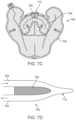
- FIGS. 7 A- 7 D illustrate an embodiment of a spacer that can be inserted between two wrap sections near or at the junction to reduce blockages within the junction area
- FIGS. 8 A and 8 B illustrate an embodiment of a shunt or stent that can be disposed within the junction to prevent blockages within the junction area.
- the therapy wrap typically includes a heat exchanger portion for circulating a heat exchange fluid, and can additionally include a compression portion to provide compression to the area being treated and to improve contact between the therapy wrap and the body part, which improves heat transfer.
- the heat exchanger portion can be a fluid bladder or chamber, while the compression portion can be a gas bladder or chamber.
- the heat exchanger portion fluid bladder
- the compression portion gas bladder
- the fluid bladder of the therapy wrap is typically connected to a fluid reservoir and the gas bladder is typically connected to an air pump. Flexible tubing can be used to provide the connections to the therapy wrap.
- the therapy wrap may be wrapped around the limb with relative ease.
- a generally rectangular therapy wrap may be adequately wrapped around an arm or a leg in many cases.
- other portions of the body such as the shoulder and neck region, have more complex geometry that may require the use of multiple therapy wraps and/or therapy wraps with a more complex geometry.
- multiple therapy wraps can be used to provide coverage of a body region with a complex geometry
- the use of multiple therapy wraps may require the use of multiple fluid reservoirs and/or multiple sets of tubing and connections, which can increase the cost, the complexity of the set up, and the clutter around the patient.
- FIGS. 1 A- 1 G illustrate an embodiment of a multi-sectional therapy wrap 100 that includes a first wrap section 102 and a second wrap section 104 that can be used to cover the upper torso, the shoulders and the neck.
- the first wrap section 102 can be wrapped around the upper torso and shoulders, while the second wrap section 104 can be wrapped around the neck.
- Both the first wrap section 102 and the second wrap section 104 can include a fluid bladder 106 , 108 that functions as a heat exchanger. Because providing compression around the neck can be uncomfortable, in some embodiments, as shown in FIGS. 1 A- 1 G , the first wrap section 102 that wraps around the upper torso and the shoulders can include an air bladder 110 for providing compression, while the second wrap section 104 can be free of the air bladder and include only the fluid bladder 108 , as illustrated in FIG. 1 G . Instead of compression from an air bladder, the second wrap section 104 can be maintained in contact with the patient's skin through other devices, such as a clasp, straps, stays, biased inserts, and/or other means, as will be described in further detail below.
- the first therapy wrap section 102 and the second therapy wrap section 104 can be joined together such that the fluid bladder 106 of the first therapy wrap section 102 is in fluid communication with the fluid bladder 108 of the second therapy wrap section 104 .
- the two therapy wrap sections can be joined together via an overlapping section between the two fluid bladders that forms a fluid box, chamber or junction 112 , as shown in FIGS. 1 A, 1 B and 1 G .
- the fluid junction 112 between the two fluid bladders allows the heat transfer fluid to pass from one fluid bladder to the other fluid bladder.
- the specialized junction 112 between the two wrap sections provides a way to create a wrap with a complex geometry and configuration, such as a wrap with two overlapping wrap sections, each with a fluid bladder on the skin facing side of the wrap section.
- the junction 112 provides a transition between the two wrap sections that is kink resistant, allows fluid flow between the two wrap sections, and accommodates virtually any geometry for the two wrap sections, where each wrap section can be made by layering together two or three sheets of material together to form the bladder(s), as described in more detail below.
- the folding method tends to create a kink or a kink prone region at the fold, and would also have limited geometry for a wrap formed from a plurality of sheets.
- the junction 112 can provide a 180 degree bend in the fluid flow path without creating a kink or fold between the wrap sections.
- the use of the junction 112 allows different types of wrap sections to be joined, with one wrap section having both a fluid bladder and a gas bladder, while the second wrap section may be a fluid bladder.
- a single manifold 116 with a fluid intake line, a fluid outlet line, and an optional gas line can be used to operate the multi-sectional therapy wrap.
- the manifold 116 can be attached to and integrated with one of the therapy wrap sections, such as the first wrap section 102 as shown.
- Fluid enters the fluid bladder of the first wrap section through the fluid intake line.
- the fluid can be directed through the first fluid bladder until it reaches the fluid junction 112 .
- the fluid passes through the fluid junction 112 from the first fluid bladder to the second fluid bladder.
- Interior fluid guides or fences 114 in both fluid bladders can guide the fluid flow along a predetermined flow path within each fluid bladder and from one fluid bladder to the other fluid bladder.
- the heat transfer fluid flows through the second fluid bladder and returns to the fluid junction 112 to flow back into the first fluid bladder.
- An interior fluid guide or fence 114 can be used to separate the fluid junction 112 into inlet and outlet portions. The fluid then flows through the remaining portion of the first fluid bladder until it reaches the fluid outlet in the manifold 116 .
- the flow path may be divided into a plurality of fluidic channels by a series of attachment points.
- the attachment points connect opposite walls of the bladder in a thickness direction.
- the exemplary attachment points, generally designated 118 may be formed by spot welding. In various respects, the attachment points are referred to informally as “dots.”
- the dots may be performed with conventional techniques such as RF or heat welding.
- the exemplary dots are circular based on the nature of the welding process, but one will appreciate that the dots may have different shapes.
- “Attachment point” is to be understood as used in the art and generally refers to points that are essentially one-dimensional as opposed to lines, shapes, and other similar features.
- the dots are similar in many respects to fences except that they are single points rather than a shape or line.
- the therapy wrap may also be constructed with a gas bladder 110 .
- the gas bladder 110 can also have interior fences 114 to help control or limit the expansion of the air bladder as it is filled with gas. Further description of general therapy wrap features and construction techniques can be found in U.S. Pat. No. 6,695,872, which is herein incorporated by reference in its entirety for all purposes.
- both wrap sections can have a peripheral fence 115 that extends around the perimeter of the wrap sections. The peripheral fence 115 can be used to join the plurality of sheets together and form a fluid or gas tight seal around the periphery of the wrap.
- the therapy wrap 100 can be used to provide thermal therapy, such as cooling, to the thoracic and cervical portion of the spine.
- the first wrap section 102 can cover the upper back and thoracic spine, while the second wrap section 104 can cover the cervical spine and portions of the neck including neck muscles.
- the first wrap section can extend further to also cover one or more of the lumbar spine and the sacral spine.
- FIGS. 2 A- 2 H illustrate one embodiment of a method of manufacturing a multi-sectional therapy wrap 200 with a junction 212 to join the first wrap section 202 with the second wrap section 204 .
- the multi-sectional therapy wrap 200 can be manufactured from a plurality of sheets of material, such as a polymer sheets or fabrics, that can be welded together using, for example, RF energy or heat.
- FIG. 2 A illustrates the construction of the fluid bladder 206 for the first wrap section 202 .
- a first sheet 220 can be aligned over a second sheet 222 , by for example, aligning the bottom edges of the sheets together.
- the second sheet 222 can be larger in one dimension than the first sheet 220 .
- the second sheet 222 can be larger in two dimensions. In some embodiments, alignment can be done with one edge, a plurality of edges, and/or the use of one or more additional alignment features.
- the second sheet 222 can be larger than the first sheet 220 to accommodate a third overlapping sheet that is used to form the second wrap section.
- a pattern of attachments points 218 can be generated by spot welding the two sheets together.
- Some interior fences 214 can also be welded at this time to provide fences 214 for the fluid bladder that are not necessarily shared with the gas bladder.
- the first sheet 220 can have a template of the microdot pattern and fence positioning marked on the sheet to guide the welding process.
- FIG. 2 B illustrates the addition of the third sheet 224 , which can be placed over the first sheet 220 to form the gas bladder 210 .
- the third sheet 224 can include interior fences 214 that can extend through both the gas bladder 210 and the fluid bladder 206 .
- the third sheet 224 can include an exterior fence 215 around the perimeter of the wrap section that can extend through both the gas bladder and the fluid bladder.
- the third sheet 224 can also include a template for the fences to guide the welding process.
- the perimeter fence 215 can have a gap 250 for the junction 212 that allows fluid to pass through from the first wrap section 202 to the second wrap section 204 .
- FIG. 2 C illustrates the formation of the junction 212 .
- the third sheet 224 can have a template to guide cuts through the sheets to the edges of the junction 212 .
- the cutting template can also extend through the first sheet 220 .
- the template to guide the cuts can be formed by creating a line of dots through welding or otherwise marking the sheets. These dot lines can be formed when forming the attachment points 218 or dots for the fluid bladder, or the dot lines can be formed separately.
- the cuts can be made to skirt along the edges of the first wrap section 202 .
- the junction 212 is positioned at the neck section of the wrap, but in other embodiments, any section of the wrap can have one or more junctions or no junction at all.
- FIG. 2 D illustrates the continued formation of the junction 212 along with the addition of the second wrap section 204 .
- the cut portion of the first sheet 220 and the third sheet 224 can be folded over against the third sheet 224 of the gas bladder to expose an underlying portion of the second sheet 222 .
- a fourth sheet 226 can be placed over the exposed, underlying portion of the second sheet 222 by aligning, for example, one edge of the fourth sheet 226 with one edge of the second sheet 222 , or by the use of additional or alternative alignment features.
- the fourth sheet 226 can then be welded or otherwise attached to the second sheet 222 , by for example, forming perimeter and interior fences 228 and attachment points 230 .
- the attachment points 230 in the second wrap section 204 can have a different spacing with a different dot or weld size than the attachment points 218 in the first wrap section 202 , especially when the second wrap section 204 is to be used as a neck wrap.
- the spacing and dot size can be the same as other wrap sections. In other embodiments, the spacing and dot size can be larger or smaller than in other wrap sections.
- the perimeter fence 228 of the second wrap section 204 can also have a gap 232 that matches the gap 250 in the perimeter fence 214 of the first wrap section 202 .
- the two gaps can be aligned together to form a portion of the junction 212 .
- the width of the gaps defines the width of the channel or flow path through the junction 212 .
- FIG. 2 E which illustrates a cross-section of the second wrap section 204 taken along the sectional line D-D in FIG. 2 D
- the fourth sheet 226 and the second sheet 222 form a second wrap section 204 that includes a single fluid bladder 208 without any gas bladder, an unfinished junction 212 , and the gas bladder 210 and fluid bladder 206 of the first wrap section 202 .
- FIGS. 2 F and 2 G illustrate the completion of the junction 212 .
- the cutout portion of the second sheet 222 with the fourth sheet 226 can be folder over against the second sheet 222 of the fluid bladder 206 of the first wrap section 202 .
- the previously folded portion of the first sheet 220 and the third sheet 224 can be unfolded so that a portion of the fourth sheet 226 with the gap 232 overlaps with the cutout portion of the first sheet 220 with the gap 250 .
- the overlapping portions of the first sheet 222 and the forth sheet 226 adjacent the gaps can be welded together to form the junction 212 between the two wrap sections.
- the junction 212 can have a perimeter fence 213 which connects the perimeter fences of the first wrap section 202 and the second wrap section 204 .
- the junction 212 can also have an interior fence 217 that that divides the junction into a first section 234 that receives fluid from the first wrap section 202 and passes fluid to the second wrap section 204 , and a second section 236 that receives fluid from the second wrap section 204 and passes fluid back to the first wrap section 202 .
- interior fence 217 of the junction 212 can also prevent or reduce kinking in the junction 212 .
- the portion of the first wrap section 202 adjacent the junction 212 can also have an interior fence 238 , shown in FIG. 2 A , that divides the first wrap section 202 into an outflow section 240 with respect to the junction 212 and an inflow section 242 with respect to the junction 212 .
- the portion of the second wrap section 204 adjacent the junction 212 can have an interior fence 244 that divides the second wrap section 204 into an inflow section 246 with respect to the junction 212 and an outflow section 248 with respect to the junction 212 .
- the interior fences 217 , 238 , 244 of the junction 212 and the portions of the wrap sections adjacent the junction 212 can all be aligned to provide a flow path from the manifold to the first wrap section 202 , from the first wrap section 202 to the junction 212 , from the junction 212 to the second wrap section 204 , through the second wrap section 204 , back to the junction 212 , and then back to the first wrap section 202 , where the flow path continues through the rest of the first wrap section 202 and back to the manifold.
- the excess sheeting can be cut from the wrap sections 202 , 204 and junction 212 , and the manifold 216 can be attached to the first wrap section 202 , although in other embodiments the manifold 216 can be attached to any of the wrap sections.
- the fluid bladder side of both wrap sections face the same direction and can be pressed against the patient's skin.
- the second wrap section 204 can be wrapped around the patient's neck while the first wrap section 202 can be wrapped around the patient's shoulders and upper back.
- the fluid sides of the wrap sections that are configured to be placed adjacent to skin can have indicators to help the patient or health care provider place and orient the wrap on the patient.
- the indicators can be a separate coloring, pattern, or marking that allows the user to distinguish the fluid side from the gas side of the wrap.
- Straps with fasteners can be used to secure the first wrap section to the patient's shoulders and upper back. Inflation of the gas bladder of the first wrap section can provide further compression of the first wrap section 202 against the patient's skin.
- a strap with fasteners can be used to secure the second wrap section 204 to the patient's neck, use of a strap may constrict the patient's airway and be uncomfortable.
- FIGS. 3 A and 3 B illustrate a clasp 300 that can be used to secure the second wrap section to a portion of the patient's neck without fully encircling the patient's neck.
- the clasp 300 When fully closed in a closed configuration, the clasp 300 retains an opening 304 between the ends of the two clasp arms 302 .
- the clasp 300 can encircle between about 50% to 90% of the patient's neck, or about 60% to 80%.
- the arms 302 can have a curved, interior surface that matches the contour of the body part to be secured, such as a portion of the patient's neck.
- the arms 302 can be rotatably attached together using a pivot 306 or hinge, which may be biased to the closed configuration by, for example, a torsion spring.
- the arms 302 can be closed by the application of a downward force provided by the patient's neck when the patient lies down.
- the pivot 306 can have a stop that prevents the arms 302 from fully closing.
- the spring or other biasing mechanism can be designed to apply a predetermined maximum level of force or pressure to the therapy wrap, or can provide an adjustable torsional force.
- the back of the arms 302 can have supports 308 that extend outwards from the arms 302 that can form a stable platform for supporting the clasp 300 and the patient's neck when the clasp 300 is in the closed configuration around the patient's neck and the patient is lying down on his or her back.
- the supports 308 can also be used to open the clasp 300 by grasping and squeezing the supports 308 together to open the arms 302 from the closed configuration to an open configuration that allows the clasp 300 to be removed from the patient's neck.
- the supports 308 can be wedge shaped with a rounded apex.
- the clasp 300 can be manufactured in several different sizes to accommodate necks of various sizes, or alternatively, the arms 302 of the clasp can be adjustable in length or circumference to cover a variety of neck sizes.
- the therapy wrap or a sleeve for holding the therapy wrap can have pockets to receive inserts 400 , which may be straight or curved and elastic or inelastic, or combinations of the above, depending on the application. Insertion of the inserts 400 into the pockets allows the wrap sections to be shaped and stiffened along predetermined forms and to bias the wrap sections towards the patient's skin. For example, insertion of a flat, curved C-shaped or collar-like insert 400 , as illustrated in FIG.
- inserts 400 into the second wrap section can bias the second wrap section into a C-shape for securement around the neck, and the insert 400 can be flexible to limit the pressure or force exerted onto the neck.
- insertion of relatively straight inserts 400 as illustrated in FIG. 4 B , or inserts 400 with a curvature matching the curvature of the spine or back of the patient into pockets in the first wrap section can be used to maintain the shape prevent the first wrap section from scrunching up from forces exerted by the straps while the wrap is being worn by the patient.
- These inserts 400 can be elongate strips or can be wider plates or sheets or material.
- the inserts 400 can be made of a plastic or metal.
- FIGS. 5 A- 5 C illustrate an alternative embodiment of a multi-sectional therapy wrap 500 similar to the embodiments described above.
- the first wrap section 502 can be joined to the second wrap section 504 using a fluid connector 506 comprising a first port 508 and a second port 510 , where one port is an inlet port and the other port is an outlet port.
- the fluid connector 506 is located on the second wrap section.
- the fluid connector can be located on any other wrap section.
- the first port 508 serves and the inlet port and the second port 510 serves as the outlet port for the second wrap section 504 .
- the fluid flow can be reversed, making the first port 508 an outlet port and the second port 510 an inlet port.
- the fluid connector 506 can be joined to a receptacle 512 than can have complementary receiving ports 514 , 516 for receiving and forming a fluid tight seal with the first port 508 and second 510 .
- the fluid connector 506 can have male fluid ports while the receptacle 512 can have complementary female fluid ports.
- the fluid connector 506 can have female fluid ports while the receptacle 508 can have male fluid ports.
- first wrap section 502 can have one or more interior fences 520 that extend from the fluid manifold 518 that defines a fluid flow path through the first wrap section
- second wrap section 504 can also have one or more interior fences 522 that define a fluid flow path through the second wrap section.
- These fluid fences can be similarly arranged for a similar function as the fences described above.
- One interior fence 522 of the second wrap section 504 can divide the fluid connector 506 into two portions, with one portion having the first port 508 and the second oprtion having the second port 510 .
- one interior fence 522 can extend between the first port 508 and the second portion 510 to form a fluid path that forces the fluid to traverse the entire wrap section as it moves from one port to the other port.
- an interior fence 520 of the first wrap section 502 can divide the receptacle 512 into two portions with one portion having one receiving port 514 and the second portion having the other receiving port 516 .
- the interior fence 520 can extend between the two receiving ports 514 , 516 to form a fluid path that forces the fluid to traverse the leave the first wrap section 502 and traverse the entire second wrap section 504 before it returns to the first wrap section 502 to complete its path through the first wrap section 502 .
- the attachment of the fluid connector 506 to the receptacle 512 can be reversible, which allows various wrap sections to be modularly joined together according to the needs of the patient. In other embodiments, the attachment of the fluid connector 506 to the receptacle 512 can be made permanent.
- the ports can be tubular or circular as shown, while in other embodiments, the ports can be rectangular, square, or have a geometry that corresponds to the shape of the fluid flow path at the fluid connector or receptacle.
- FIGS. 6 A and 6 B illustrate a potential blockage point around the junction 612 of a multi-sectional therapy wrap 600 that connects a first wrap section 602 with a second wrap section 604 .
- This blockage may occur as the flow of fluid passes from one wrap section into the junction 612 , particularly when the wrap section only is made from a single fluid layer, such as a neck wrap formed from a single fluid layer.
- the fluid may push down a portion of the bladder wall to form a blockage 650 that can impede fluid flow through the therapy wrap 600 .
- FIG. 7 A- 7 D illustrate one embodiment of a spacer 760 that can be positioned at the junction 712 of the multi-sectional therapy wrap 700 between the exterior fluid sides of both the first wrap section 702 and the second wrap section 704 .
- the spacer 760 can provide separation and support to the layers around the junction 712 that prevents or reduces the likelihood of formation of the blockage.
- the spacer 760 can be about the same width as the junction 712 and can have at least one straight side 762 that can abut against the junction 712 .
- the junction 712 can otherwise have various shapes, such as the half circle shown, or be square or rectangular.
- An adhesive can be used to attach the spacer 760 to one of the wrap sections, such as the neck wrap section.
- a fastener 764 such as a button type fastener formed from a socket 766 and stud 768 , can be used reversibly secure the spacer 760 against the other wrap section in the proper configuration.
- the fastener 764 can be placed through an opening 770 in the spacer 760 .
- One part of the fastener 764 such as the socket 766
- the other part of the fastener 764 such as the stud 768
- the spacer 760 can be placed on one of the wrap sections by aligning the opening 770 with one of the fastener 764 parts, either the socket 766 or stud 768 .
- the fastener connection to the bladder can be made leak free by welding one or more perimeter shapes, such as a circle or concentric circles, around the fastener 764 to prevent leaks between the fastener location and the bladder.
- the weld may be performed during the welding of the main body and neck weld operations, or may be done at once, during the junction weld to ensure proper registration.
- the spacer may be sufficiently thick so as to allow the fastener to be sublet below the surface of the spacer, thus protecting the body from uncomfortable contact with the fastener. In other words, in some embodiments, the spacer 760 may by thicker than the height of the fastener 764 .
- the spacer 760 can be made of foam or a gel pad or some other material that provides both physical support, can provide spacing between the wrap sections, and is compliant or resilient so that the therapy wrap can be conformed against the patient's skin. In some embodiments, the spacer 760 can be between about 2 mm to 20 mm in thickness.
- FIGS. 8 A and 8 B illustrates an embodiment of a shunt 850 or stent that can be inserted into the junction 812 of the therapy wrap to ensure that flow between the first wrap section 802 and second wrap section 804 is not impeded.
- the shunt 850 can be a structural member with a lumen that props open the channels within the junction 812 and surrounding portions of the wrap sections.
- the shunt 850 can be tubular or have a cross-sectional profile that matches the shape of the fluid channel in which it is disposed.
- the shunt 850 can be U shaped to provide structural support from the first wrap section 802 , through the junction 812 , and to the second wrap section 804 .
- the shunt 850 is disposed within the fluid channels to provide additional structural support to the fluid channels.
- a shunt 850 can be disposed within each half of the junction 812 to provide complete support to the junction 812 .
- junctions and portions of the wrap sections adjacent the junction can be made of structurally stiffer materials, or reinforcing members or layers can be added to increase the stiffness, relative to other portions of the therapy wrap.
- the multi-sectional therapy wraps described herein can be used to treat body parts with a relative complex geometry, such as the foot and ankle region, the head and neck region, the shoulder region, the pelvic region, and the like.
- the therapy wrap may have three or more wrap sections.
- each of the wrap sections can be fluidically connected to one of the other wrap sections, thereby allowing the entire therapy wrap to be supplied with fluid using a single fluid manifold located on one of the wrap sections.
Abstract
Description
Claims (18)
Priority Applications (1)
| Application Number | Priority Date | Filing Date | Title |
|---|---|---|---|
| US16/178,467 US11672693B2 (en) | 2014-08-05 | 2018-11-01 | Integrated multisectional heat exchanger |
Applications Claiming Priority (4)
| Application Number | Priority Date | Filing Date | Title |
|---|---|---|---|
| US201462033569P | 2014-08-05 | 2014-08-05 | |
| US201462057091P | 2014-09-29 | 2014-09-29 | |
| US14/819,276 US20160038336A1 (en) | 2014-08-05 | 2015-08-05 | Integrated multisectional heat exchanger |
| US16/178,467 US11672693B2 (en) | 2014-08-05 | 2018-11-01 | Integrated multisectional heat exchanger |
Related Parent Applications (1)
| Application Number | Title | Priority Date | Filing Date |
|---|---|---|---|
| US14/819,276 Continuation US20160038336A1 (en) | 2014-08-05 | 2015-08-05 | Integrated multisectional heat exchanger |
Publications (2)
| Publication Number | Publication Date |
|---|---|
| US20190133817A1 US20190133817A1 (en) | 2019-05-09 |
| US11672693B2 true US11672693B2 (en) | 2023-06-13 |
Family
ID=55264493
Family Applications (2)
| Application Number | Title | Priority Date | Filing Date |
|---|---|---|---|
| US14/819,276 Abandoned US20160038336A1 (en) | 2014-08-05 | 2015-08-05 | Integrated multisectional heat exchanger |
| US16/178,467 Active 2037-07-24 US11672693B2 (en) | 2014-08-05 | 2018-11-01 | Integrated multisectional heat exchanger |
Family Applications Before (1)
| Application Number | Title | Priority Date | Filing Date |
|---|---|---|---|
| US14/819,276 Abandoned US20160038336A1 (en) | 2014-08-05 | 2015-08-05 | Integrated multisectional heat exchanger |
Country Status (5)
| Country | Link |
|---|---|
| US (2) | US20160038336A1 (en) |
| EP (1) | EP3177242B1 (en) |
| CN (1) | CN106714743B (en) |
| CA (1) | CA2994526C (en) |
| WO (1) | WO2016022675A1 (en) |
Families Citing this family (10)
| Publication number | Priority date | Publication date | Assignee | Title |
|---|---|---|---|---|
| US7896910B2 (en) | 2004-05-17 | 2011-03-01 | Coolsystems, Inc. | Modular apparatus for therapy of an animate body |
| US9615967B2 (en) | 2010-12-30 | 2017-04-11 | Coolsystems, Inc. | Reinforced therapeutic wrap and method |
| WO2016022675A1 (en) | 2014-08-05 | 2016-02-11 | Coolsystems, Inc. | Integrated multisectional heat exchanger |
| JP6787903B2 (en) | 2015-01-27 | 2020-11-18 | メディヴァンス インコーポレイテッドMedivance,Inc. | Improved medical pads and systems for hyperthermia |
| US10859295B2 (en) | 2016-04-13 | 2020-12-08 | ZeoThermal Technologies, LLC | Cooling and heating platform |
| TWI618530B (en) * | 2016-09-30 | 2018-03-21 | Li Ke Sen | Constant temperature liquid circulation type cooling and heating covering structure |
| JP6885384B2 (en) * | 2018-10-12 | 2021-06-16 | 株式会社富士通ゼネラル | Body heating and cooling device |
| CN113491612A (en) * | 2020-03-18 | 2021-10-12 | 锐可医疗科技(苏州)有限公司 | Cold and hot compress wrapping bag, manufacturing method thereof and cold and hot compress circulating system |
| EP4000567A1 (en) * | 2020-11-11 | 2022-05-25 | Hilotherm Holding AG | Device for the heat treatment of a selected part of the body of a human or animal and method for operating this device |
| WO2022165068A1 (en) * | 2021-01-27 | 2022-08-04 | C.R. Bard, Inc. | Soft border for targeted temperature management |
Citations (457)
| Publication number | Priority date | Publication date | Assignee | Title |
|---|---|---|---|---|
| US1886768A (en) | 1929-02-25 | 1932-11-08 | Stewart M Watson | Outlining device |
| US1958899A (en) | 1931-06-30 | 1934-05-15 | Macadams Jesse Edward | Heat transfer apparatus |
| FR819022A (en) | 1937-03-10 | 1937-10-08 | Anciens Etablissements Lamblin | Cooling radiator for airplanes and other applications. |
| US2146622A (en) | 1937-06-21 | 1939-02-07 | Carlo Simon | Sweep operated windlass |
| US2148661A (en) | 1936-04-29 | 1939-02-28 | Schaeffer Carl | Therapeutic method and apparatus |
| US2413386A (en) | 1944-08-11 | 1946-12-31 | Carrier Corp | Suit for circulating conditioned air about a person |
| US2510125A (en) | 1946-07-30 | 1950-06-06 | Lawrence W Meakin | Connector for fluid or electrical lines or both |
| US2531074A (en) | 1947-06-03 | 1950-11-21 | Gerald W Miller | Pneumatic massage |
| US2540547A (en) | 1947-03-24 | 1951-02-06 | Stewart Warner Corp | Air-conditioned garment |
| US2608690A (en) | 1949-09-27 | 1952-09-02 | Philip C Kolb | Outer garment |
| US2703770A (en) | 1952-04-15 | 1955-03-08 | Melzer Jean | Manufacture of flat inflatable objects |
| US2726658A (en) | 1953-04-27 | 1955-12-13 | Donald E Chessey | Therapeutic cooling devices for domestic and hospital use |
| US2954898A (en) | 1959-10-19 | 1960-10-04 | Lois R Freeberg | Kit structure |
| US3261042A (en) | 1964-04-14 | 1966-07-19 | Gentex Corp | Buoyant jacket |
| US3320682A (en) | 1965-03-02 | 1967-05-23 | Michael T Sliman | Curler bonnet |
| US3354898A (en) | 1966-05-02 | 1967-11-28 | Standard Screw | Crankcase ventilating valve having rotatable metering plunger |
| US3559640A (en) | 1968-10-16 | 1971-02-02 | Orval D Beckett | Double arm-sling jacket |
| US3561435A (en) | 1968-11-15 | 1971-02-09 | Dev Inc | Combined splint and coolant container |
| US3738367A (en) | 1971-02-11 | 1973-06-12 | Angelica Corp | Patient garment with temperature control |
| US3744555A (en) | 1971-11-12 | 1973-07-10 | Gen Electric | Automatic control of liquid cooling garment by cutaneous and external auditory meatus temperatures |
| US3830676A (en) | 1973-02-28 | 1974-08-20 | Acurex Corp | Process of making a contoured thermal device |
| US3867939A (en) * | 1972-05-18 | 1975-02-25 | Moore Perk Corp | Disposable, sterile temperature control applicator pad for medical application |
| US3871381A (en) | 1971-12-30 | 1975-03-18 | Donald J Roslonski | Cold compress device |
| US3901225A (en) | 1974-01-02 | 1975-08-26 | Jerry W Sconce | Inflatable splint |
| US3993053A (en) | 1974-08-05 | 1976-11-23 | Murray Grossan | Pulsating massage system |
| US4020209A (en) | 1973-05-04 | 1977-04-26 | E. I. Du Pont De Nemours And Company | Coated fabrics and laminated articles therefrom |
| US4026299A (en) | 1975-09-26 | 1977-05-31 | Vari-Temp Manufacturing Co. | Cooling and heating apparatus |
| US4116476A (en) | 1977-11-11 | 1978-09-26 | Porter Gary K | Quick disconnect coupler assembly |
| US4118946A (en) | 1976-11-23 | 1978-10-10 | Eddie Sam Tubin | Personnel cooler |
| US4147921A (en) | 1977-09-09 | 1979-04-03 | Clairol Inc. | Heat treating articles |
| US4149541A (en) | 1977-10-06 | 1979-04-17 | Moore-Perk Corporation | Fluid circulating pad |
| US4149529A (en) | 1977-09-16 | 1979-04-17 | Jobst Institute, Inc. | Portable thermo-hydraulic physiotherapy device |
| US4170998A (en) | 1975-09-26 | 1979-10-16 | Chattanooga Pharmacal Company | Portable cooling apparatus |
| US4184537A (en) | 1975-09-26 | 1980-01-22 | Chattanooga Pharmacal Company | Selective heating and cooling apparatus |
| US4194247A (en) | 1977-10-31 | 1980-03-25 | East Wind Industries, Inc. | Wearable ventilation system |
| US4206751A (en) * | 1978-03-31 | 1980-06-10 | Minnesota Mining And Manufacturing Company | Intermittent compression device |
| US4320746A (en) | 1979-12-07 | 1982-03-23 | The Kendall Company | Compression device with improved pressure control |
| US4335726A (en) | 1980-07-11 | 1982-06-22 | The Kendall Company | Therapeutic device with temperature and pressure control |
| US4338944A (en) | 1980-06-16 | 1982-07-13 | The Kendall Company | Therapeutic device |
| USD269379S (en) | 1981-01-02 | 1983-06-14 | Medical Designs, Inc. | Articulate knee brace |
| US4407276A (en) | 1981-01-22 | 1983-10-04 | Medical Designs, Inc. | Brace for articulated limbs |
| US4412648A (en) | 1982-04-01 | 1983-11-01 | Ammark Corporation | Control valve assembly for steam radiators |
| US4436125A (en) | 1982-03-17 | 1984-03-13 | Colder Products Company | Quick connect coupling |
| US4441504A (en) | 1982-05-10 | 1984-04-10 | Stoelting Company | Electronic cuff to monitor blood pressure in polygraph instruments |
| US4460085A (en) | 1981-09-10 | 1984-07-17 | Eric Jantzen | Portable tool-chest |
| US4463751A (en) | 1982-12-27 | 1984-08-07 | Bledsoe Gary R | Stabilizing knee hinge |
| US4471759A (en) | 1981-04-28 | 1984-09-18 | B. Shawn Buckley | Method of forming a solar collector or hot water storage tank and solar water heating apparatus using same |
| US4478436A (en) | 1979-11-05 | 1984-10-23 | Aisin Seiki Kabushiki Kaisha | Hose connector |
| DE3343664C1 (en) | 1983-12-02 | 1985-03-28 | Paul Richard 6990 Bad Mergentheim Gembrys | Device for the therapeutic tempering of body parts |
| US4547906A (en) | 1983-06-27 | 1985-10-22 | Kanebo, Ltd. | Heat retaining article |
| US4550828A (en) | 1985-02-22 | 1985-11-05 | Arthur Baldwin | Portable tool box |
| US4597384A (en) | 1984-06-29 | 1986-07-01 | Gaymar Industries, Inc. | Sequential compression sleeve |
| US4678027A (en) | 1984-12-14 | 1987-07-07 | Paul Mueller Company | Dual-walled coiled plate heat exchanger with vented interface |
| US4691762A (en) | 1983-04-01 | 1987-09-08 | Life Support Systems, Inc. | Personal temperature control system |
| US4699613A (en) | 1985-12-23 | 1987-10-13 | Donawick William J | Apparatus for the gravitational administration of fluids and drugs to large animals |
| US4718429A (en) | 1983-03-10 | 1988-01-12 | Udo Smidt | Method of reducing fatty deposits in the human body |
| US4738119A (en) | 1987-02-09 | 1988-04-19 | Westinghouse Electric Corp. | Integral cooling garment for protection against heat stress |
| US4753268A (en) | 1986-09-01 | 1988-06-28 | S.A. Des Establissements Staubli | Double coupling for removably joining twin pipes |
| US4765338A (en) | 1982-12-29 | 1988-08-23 | Turner Richard W | Reuseable heat transfer devices for the scalp |
| US4817588A (en) | 1987-07-01 | 1989-04-04 | Medical Technology, Inc. | Motion restraining knee brace |
| US4834073A (en) | 1987-02-20 | 1989-05-30 | Medical Technology, Inc. | Passive motion exerciser |
| US4844072A (en) | 1985-12-27 | 1989-07-04 | Seabrook Medical Systems, Inc. | Liquid-circulating thermal therapy system |
| US4884304A (en) | 1988-09-28 | 1989-12-05 | Life Support Systems, Inc. | Bedding system with selective heating and cooling |
| EP0344949A2 (en) | 1988-05-31 | 1989-12-06 | Novamedix Ltd. | Medical appliance for the hand |
| US4925603A (en) | 1981-05-16 | 1990-05-15 | Nippon Oil Co., Ltd. | Process for the preparation of gel for use as cooling medium |
| US4955435A (en) | 1987-04-08 | 1990-09-11 | Du Pont Canada, Inc. | Heat exchanger fabricated from polymer compositions |
| US4955369A (en) | 1988-10-27 | 1990-09-11 | Bledsoe Gary R | Dynamically shiftable counter shear force knee brace |
| US4962761A (en) | 1987-02-24 | 1990-10-16 | Golden Theodore A | Thermal bandage |
| US4964282A (en) | 1989-12-07 | 1990-10-23 | Wagner Christopher S | Detachable bulletproof vest air conditioning apparatus |
| US4964402A (en) | 1988-08-17 | 1990-10-23 | Royce Medical Company | Orthopedic device having gel pad with phase change material |
| US4966145A (en) | 1987-03-19 | 1990-10-30 | Agency Of Industrial Science & Technology | Automatic body temperature adjuster |
| US4976262A (en) | 1989-01-27 | 1990-12-11 | Jed Palmacci | Ice bag holding device |
| EP0412708A1 (en) | 1989-08-07 | 1991-02-13 | Daily, Pat O. as Trustee under the Pat O. Daily Revocable Trust | Arcuate shaped cooling jacket |
| US5002270A (en) | 1990-01-22 | 1991-03-26 | Shine Anthony G | Exercise vest |
| US5014695A (en) | 1988-10-04 | 1991-05-14 | Benak Arnold M | Kidney cooling jacket |
| US5022109A (en) | 1990-06-11 | 1991-06-11 | Dielectrics Industries | Inflatable bladder |
| US5033136A (en) | 1988-09-28 | 1991-07-23 | Life Support Systems, Inc. | Bedding system with selective heating and cooling |
| US5052725A (en) | 1989-03-13 | 1991-10-01 | Colder Products Company | Two piece molded female coupling |
| US5056563A (en) | 1989-06-02 | 1991-10-15 | Ronald Glossop | High pressure gas charging apparatus |
| US5072875A (en) | 1990-03-15 | 1991-12-17 | Federal Leasing Rehab Company | Apparatus for controlling the temperature of an area of the body |
| US5074285A (en) | 1989-11-20 | 1991-12-24 | Wright Linear Pump, Inc. | Thermal applicator method |
| US5076068A (en) | 1989-07-31 | 1991-12-31 | Kkw Kulmbacher Klimagerate-Werk Gmbh | Cooling device for a plurality of coolant circuits |
| US5080089A (en) | 1990-09-05 | 1992-01-14 | Breg, Inc. | Therapeutic apparatus applying compression and a nonambient temperature fluid |
| US5080166A (en) | 1987-04-15 | 1992-01-14 | Itrag Ag | Plate-shaped heating element, in particular for floor heating |
| US5086771A (en) | 1991-09-05 | 1992-02-11 | Cincinnati Sub-Zero Products, Inc. | Configured pad for therapeutic cooling effect |
| US5097829A (en) | 1990-03-19 | 1992-03-24 | Tony Quisenberry | Temperature controlled cooling system |
| US5104158A (en) | 1989-03-13 | 1992-04-14 | Colder Products Company | Two piece molded female coupling |
| US5112045A (en) | 1990-09-05 | 1992-05-12 | Breg, Inc. | Kinesthetic diagnostic and rehabilitation device |
| US5113877A (en) | 1991-03-06 | 1992-05-19 | Aircast Incorporated | Ankle sprain management system |
| WO1992013506A2 (en) | 1991-01-23 | 1992-08-20 | Aircast, Inc. | Thermal compress system |
| US5163425A (en) | 1985-05-27 | 1992-11-17 | Masao Nambu | Deformable cap for scalp cooling |
| US5163923A (en) | 1991-09-27 | 1992-11-17 | International Win, Ltd. | Apparatus for the administration of fluids to a small animal |
| US5172689A (en) | 1990-03-01 | 1992-12-22 | Wright Christopher A | Cryogenic sleeve for providing therapeutic compression |
| US5186698A (en) | 1991-06-20 | 1993-02-16 | Breg, Inc. | Ankle exercise system |
| EP0535830A1 (en) | 1991-09-30 | 1993-04-07 | Breg, Inc. | Apparatus for thermally treating the body or parts thereof |
| US5201552A (en) | 1990-11-23 | 1993-04-13 | Rasmussen Gmbh | Twin hose coupling |
| US5232020A (en) | 1990-09-05 | 1993-08-03 | Breg, Inc. | Shutoff valve having a unitary valve body |
| US5243706A (en) | 1991-09-13 | 1993-09-14 | Minister Of National Defence Of Her Majesty's Canadian Government | Micro-climate conditioning clothing |
| US5269369A (en) | 1991-11-18 | 1993-12-14 | Wright State University | Temperature regulation system for the human body using heat pipes |
| US5294156A (en) | 1991-02-20 | 1994-03-15 | Nippondenso Co., Ltd. | Flange coupling for connecting pipes for carrying refrigerant during refrigerating cycle |
| USD345609S (en) | 1992-03-12 | 1994-03-29 | Breg, Inc. | Therapeutic fluid circulation pad |
| USD345803S (en) | 1992-03-12 | 1994-04-05 | Breg, Inc. | Therapeutic fluid flow controller |
| USD345802S (en) | 1992-03-12 | 1994-04-05 | Breg, Inc. | Therapeutic fluid pump |
| US5303716A (en) | 1992-11-12 | 1994-04-19 | Breg, Inc. | Portable device for rehabilitative exercise of the leg |
| US5305712A (en) | 1992-11-30 | 1994-04-26 | Allegheny-Singer Research Institute | Animal tether system and method of use |
| WO1994009732A1 (en) | 1992-10-29 | 1994-05-11 | Aircast, Inc. | Automatic fluid circulating system and method |
| US5314455A (en) | 1991-01-23 | 1994-05-24 | Aircast, Inc. | Thermal compress system |
| US5316547A (en) | 1992-07-01 | 1994-05-31 | Smith & Nephew Donjoy, Inc. | Orthopedic brace having pneumatic pads |
| US5316250A (en) | 1992-07-01 | 1994-05-31 | Breg, Inc. | Fluid container stand for therapeutic treatments |
| USD348106S (en) | 1992-12-07 | 1994-06-21 | Breg, Inc. | Therapeutic fluid circulation pad for body joints |
| US5324319A (en) | 1990-09-05 | 1994-06-28 | Breg, Inc. | Gravity driven therapeutic fluid circulation device |
| USD348518S (en) | 1992-12-07 | 1994-07-05 | Breg, Inc. | Therapeutic fluid circulation pad for the breasts |
| US5352174A (en) | 1991-07-26 | 1994-10-04 | Breg, Inc. | Shoulder exercise system |
| US5354101A (en) | 1993-09-13 | 1994-10-11 | General Motors Corporation | Sealing washer block connection |
| USD351472S (en) | 1992-12-07 | 1994-10-11 | Breg, Inc. | Therapeutic fluid circulation pad for the eyes |
| US5353605A (en) | 1992-10-28 | 1994-10-11 | Coolight Research & Development Ltd. | Personal air cooling device |
| US5354103A (en) | 1994-01-28 | 1994-10-11 | Eaton Corporation | Quick connect conduit coupling |
| USD352781S (en) | 1992-03-12 | 1994-11-22 | Breg, Inc. | Therapeutic fluid flow line |
| US5372575A (en) | 1993-02-16 | 1994-12-13 | Safeguard Industrial Corporation | Therapeutic forearm appliance having pressure pad containing parallel chambers |
| US5383919A (en) | 1993-05-18 | 1995-01-24 | Danninger Medical Technology, Inc. | Thermal therapy pad |
| US5383689A (en) | 1993-07-09 | 1995-01-24 | Wilkerson Corporation | Separable connector for pressure fluid components |
| US5395399A (en) | 1993-06-14 | 1995-03-07 | Sport Wrapz, Inc. | Thermal wrap for a body member |
| USRE34883E (en) | 1989-02-08 | 1995-03-21 | Royce Medical Company | Simplified orthopaedic back support |
| US5407421A (en) | 1994-05-18 | 1995-04-18 | Goldsmith; Seth | Compressive brace |
| US5411541A (en) * | 1993-08-05 | 1995-05-02 | Oansh Designs Ltd. | Portable fluid therapy device |
| US5415625A (en) | 1992-07-01 | 1995-05-16 | Smith & Nephew Donjoy, Inc. | Orthopedic brace having a system of alternately inflatable or deflatable pneumatic pads for adjustable fitting of the brace to the body |
| US5417720A (en) | 1990-09-05 | 1995-05-23 | Breg, Inc. | Nonambient temperature pad conformable to a body for therapeutic treatment thereof |
| US5427577A (en) | 1992-01-17 | 1995-06-27 | Dba Products Co. Inc. | Selectively pneumatic bowling glove |
| US5449379A (en) | 1993-07-21 | 1995-09-12 | Alternative Compression Technologies, Inc. | Apparatus for applying a desired temperature and pressure to an injured area |
| US5451201A (en) | 1992-09-24 | 1995-09-19 | Innovative Footwear Corporation | Joint support apparatus |
| US5466250A (en) | 1991-01-23 | 1995-11-14 | Aircast, Inc. | Automatic fluid compress and circulating system |
| US5468220A (en) | 1995-02-27 | 1995-11-21 | Sucher; Benjamin M. | Carpal tunnel bracelet |
| US5470353A (en) | 1993-10-20 | 1995-11-28 | Hollister Incorporated | Post-operative thermal blanket |
| US5476489A (en) | 1994-01-28 | 1995-12-19 | Seabrook Medical Systems, Inc. | Cold therapy system |
| US5484448A (en) | 1993-05-07 | 1996-01-16 | Steele And Associates, Inc. | Garment and method for cooling body temperature |
| US5494074A (en) | 1992-10-27 | 1996-02-27 | Colder Products Company | Quick connection coupling valve assembly |
| US5496358A (en) | 1993-06-14 | 1996-03-05 | Sport Wrapz, Inc. | Thermal wrap for a body member |
| US5507792A (en) | 1990-09-05 | 1996-04-16 | Breg, Inc. | Therapeutic treatment device having a heat transfer element and a pump for circulating a treatment fluid therethrough |
| US5514081A (en) | 1994-10-07 | 1996-05-07 | D'mannco, Inc. | Elbow orthosis having an inflatable bladder support and method of use |
| US5520622A (en) | 1992-07-01 | 1996-05-28 | Smith & Nephew Donjoy Inc. | Orthopedic brace having a pneumatic pad and associated pump |
| US5524293A (en) | 1994-05-03 | 1996-06-11 | Kung; King Y. | Cooling vest |
| US5527268A (en) | 1992-07-01 | 1996-06-18 | Smith & Nephew Donjoy Inc. | Orthopedic knee brace and associated knee condyle pad |
| US5533354A (en) | 1994-09-20 | 1996-07-09 | Texan Corporation | Personal comfort apparatus |
| US5539934A (en) | 1993-11-24 | 1996-07-30 | Ponder; Christopher W. | Protective helmet cooling apparatus |
| USD372534S (en) | 1995-05-16 | 1996-08-06 | Hewlett-Packard Company | Defibrillator |
| WO1996026693A1 (en) | 1995-03-01 | 1996-09-06 | Shannon Cool Limited | Applying thermal therapy to living tissue |
| JPH08229061A (en) | 1995-02-23 | 1996-09-10 | Shimadzu Corp | Body temperature cooling/heating device |
| US5553712A (en) | 1995-05-05 | 1996-09-10 | Suncast Corporation | Trading card carrying and display case |
| US5554119A (en) | 1991-08-02 | 1996-09-10 | Scimed | Drug delivery catheter with manifold |
| US5556138A (en) | 1994-03-28 | 1996-09-17 | Nippondenso Co., Ltd. | Pipe connecting device |
| US5564124A (en) | 1995-04-20 | 1996-10-15 | Bio-Medical Devices, Inc | Personal body ventilation system |
| US5569172A (en) | 1994-08-02 | 1996-10-29 | Padden; John | Device for supporting and immobilizing a patient's arm and shoulder and method thereof |
| US5592694A (en) | 1993-09-16 | 1997-01-14 | Yewer, Jr.; Edward H. | Wrap type hand glove |
| US5609620A (en) | 1995-06-06 | 1997-03-11 | Pat O. Daily | Cardiac cooling jacket |
| US5630328A (en) | 1995-09-22 | 1997-05-20 | Consolidated Natural Gas Service Company, Inc. | Natural gas conditioning facility |
| US5634940A (en) | 1995-12-13 | 1997-06-03 | Panyard; Albert A. | Therapeutic structure and methods |
| US5638707A (en) | 1995-12-28 | 1997-06-17 | Gould; Murray J. | Protective cover for a lock box |
| US5645671A (en) | 1994-12-30 | 1997-07-08 | Smith & Nephew Donjoy Inc. | Method for manufacturing composite pads |
| USD382113S (en) | 1995-11-15 | 1997-08-12 | Storehorse, Inc. | Tool box |
| US5662695A (en) | 1990-09-05 | 1997-09-02 | Breg, Inc. | Occlusion-resistant fluid pad conformable to a body for therapeutic treatment thereof |
| US5662239A (en) | 1996-10-15 | 1997-09-02 | Heuvelman; George M. | Medicinal container with complete instructions |
| USD383547S (en) | 1996-06-04 | 1997-09-09 | Breg, Inc. | Cold therapy pad with mounting straps |
| USD383848S (en) | 1996-06-04 | 1997-09-16 | Breg, Inc. | Cold therapy pad |
| US5672152A (en) | 1995-11-28 | 1997-09-30 | Breg, Inc. | Hinge for an orthopedic brace having an adjustable range of rotation |
| US5683118A (en) | 1996-02-12 | 1997-11-04 | Aesop, Inc. | Kinematic coupling fluid couplings and method |
| DE29716336U1 (en) | 1997-09-11 | 1997-12-04 | Hille Klaus Dipl Ing | Combination temperature control sleeve |
| DE29716338U1 (en) | 1997-09-11 | 1997-12-04 | Hille Klaus Dipl Ing | Temperature control sleeve with kink protection |
| US5716388A (en) | 1995-10-24 | 1998-02-10 | Petelle; Paula A. | Flexible pouch for thermal therapy pack |
| WO1998007397A1 (en) | 1996-08-20 | 1998-02-26 | Kolen Paul T | Applying thermal therapy |
| US5728058A (en) | 1995-06-29 | 1998-03-17 | The Procter & Gamble Company | Elastic knee wrap |
| US5732464A (en) | 1996-08-21 | 1998-03-31 | Seagate Technology, Inc. | Method of facilitating installation or use of an electromechanical information-storage device drive assembly |
| US5755275A (en) | 1995-01-25 | 1998-05-26 | Delta Temax Inc. | Tubed lamination heat transfer articles and method of manufacture |
| US5755755A (en) | 1995-12-13 | 1998-05-26 | Panyard; Albert A. | Therapeutic structure and method |
| US5769801A (en) | 1993-06-11 | 1998-06-23 | Ndm Acquisition Corp. | Medical pumping apparatus |
| US5772618A (en) | 1996-05-31 | 1998-06-30 | Breg, Inc. | Hinge for an orthopedic brace |
| US5782780A (en) | 1996-07-31 | 1998-07-21 | Breg, Inc. | Method of forming a contoured orthotic member |
| US5792216A (en) | 1994-06-21 | 1998-08-11 | Mallincrodt Medical, Inc. | Methods of preventing hypothermia using an upper body warming blanket |
| US5807294A (en) | 1997-03-21 | 1998-09-15 | Breg, Inc. | Adjustable hinge assembly for an osteoarthritic knee brace |
| US5827208A (en) | 1995-11-28 | 1998-10-27 | Breg, Inc, | Hinge for an orthopedic brace having a selectively positionable stop to limit rotation |
| US5833638A (en) | 1996-06-10 | 1998-11-10 | Nelson; Ronald E. | Back brace |
| CN2304378Y (en) | 1997-03-05 | 1999-01-20 | 石汉平 | Medical cold and hot compress instrument |
| US5862675A (en) | 1997-05-30 | 1999-01-26 | Mainstream Engineering Corporation | Electrically-driven cooling/heating system utilizing circulated liquid |
| US5865841A (en) | 1995-03-01 | 1999-02-02 | Kolen; Paul T. | Cold therapy apparatus |
| US5866219A (en) | 1996-10-30 | 1999-02-02 | Product Engineering, Inc. | Product information label system |
| US5868690A (en) | 1997-04-30 | 1999-02-09 | Eischen, Sr.; Clement G. | Inflatable boot and method for its manufacture |
| US5871526A (en) | 1993-10-13 | 1999-02-16 | Gibbs; Roselle | Portable temperature control system |
| US5895418A (en) | 1994-09-30 | 1999-04-20 | Saringer Research Inc. | Device for producing cold therapy |
| US5913885A (en) | 1991-05-22 | 1999-06-22 | Life Science Holdings, Inc. | Brain cooling device and method for cooling |
| US5920934A (en) | 1996-08-09 | 1999-07-13 | Pegasus Airwave Limited | Readily separable, three mode connector for air-inflatable support |
| KR200153967Y1 (en) | 1997-08-21 | 1999-08-02 | 김홍주 | An apparatus getting away for the summer |
| WO1999044552A1 (en) | 1998-03-05 | 1999-09-10 | M.T.R.E. Advanced Technology Ltd. | System and method for heat control of a living body |
| US5951598A (en) | 1997-01-14 | 1999-09-14 | Heartstream, Inc. | Electrode system |
| US5968072A (en) | 1993-12-20 | 1999-10-19 | Medical Wraps, Inc. | Method and apparatus for cold compression treatment of wounds |
| US5967225A (en) | 1998-01-16 | 1999-10-19 | Jenkins; Donny Ray | Body heating/cooling apparatus |
| US5970519A (en) | 1998-02-20 | 1999-10-26 | Weber; Stanley | Air cooling garment for medical personnel |
| US5984885A (en) | 1996-07-16 | 1999-11-16 | Medical Specialties, Inc. | Industrial back support |
| US5989285A (en) | 1996-08-15 | 1999-11-23 | Thermotek, Inc. | Temperature controlled blankets and bedding assemblies |
| US5992459A (en) | 1997-06-25 | 1999-11-30 | Kabushiki Kaisha Saginomiya Seisakusho | Rotary flow-path exchanging valve |
| US5997495A (en) | 1995-04-08 | 1999-12-07 | Novamedix Distribution Ltd | Medical device for the hand |
| US6030412A (en) | 1991-05-22 | 2000-02-29 | Life Science Holdings, Inc. | Apparatus and method for cooling the brain, brain stem and associated neurologic tissues |
| US6036107A (en) | 1998-03-31 | 2000-03-14 | Spraying System Co. | Control valve arrangement for spraying systems |
| US6036718A (en) | 1998-07-02 | 2000-03-14 | Welch Allyn, Inc. | Bladderless blood pressure cuff |
| US6048326A (en) | 1996-12-31 | 2000-04-11 | The Procter & Gamble Company | Disposable elastic thermal knee wrap |
| US6053169A (en) | 1999-02-22 | 2000-04-25 | Hunt; Dermot A. | Medical strap for treating injured patient |
| WO2000023016A1 (en) | 1998-10-16 | 2000-04-27 | Aircast, Inc. | Post-operative therapeutic device for amputees |
| US6055670A (en) | 1999-04-13 | 2000-05-02 | Parker; Kirk A. | Breath-heated insulated glove and associated method |
| US6058508A (en) | 1998-10-26 | 2000-05-09 | Brown Honeysuckle; Jelane N. | Adjustable garment |
| US6074413A (en) | 1996-12-31 | 2000-06-13 | The Procter & Gamble Company | Disposable elastic thermal back wrap |
| US6083256A (en) | 1996-08-15 | 2000-07-04 | Der Ovanesian; Mary | NNT or cold pad with inner element |
| US6089593A (en) | 1997-02-10 | 2000-07-18 | Hill-Rom, Inc. | Ambulatory care chair |
| US6105382A (en) | 1999-03-29 | 2000-08-22 | The United States Of America As Represented By The Secretary Of The Navy | Chest mounted armored microclimate conditioned air device |
| USD430288S (en) | 1999-07-30 | 2000-08-29 | Breg, Inc. | Medical infusion pump |
| USD430289S (en) | 1999-07-30 | 2000-08-29 | Breg, Inc. | Infusion pump for administering a fluid medication |
| US6109338A (en) | 1997-05-01 | 2000-08-29 | Oceaneering International, Inc. | Article comprising a garment or other textile structure for use in controlling body temperature |
| US6117164A (en) | 1997-06-06 | 2000-09-12 | Dj Orthopedics, Llc | Flexible multijoint therapeutic pads |
| WO2000055542A1 (en) | 1999-03-18 | 2000-09-21 | Mareck B.V. | A method and device for supervision and control of a heat generator with pulsating combustion |
| JP2000288007A (en) | 1999-04-01 | 2000-10-17 | Art Heaven Nine:Kk | Body temperature adjusting clothes |
| US6146347A (en) | 1998-06-01 | 2000-11-14 | Porrata; Humberto L. | Appliance and method for treating carpal tunnel syndrome |
| US6146413A (en) | 1997-09-18 | 2000-11-14 | Harman; Susan | Therapeutic cold pack for hand, wrist and forearm |
| WO2000067685A1 (en) | 1999-05-12 | 2000-11-16 | Burns Terrence R | Thermoregulation systems |
| US6156059A (en) | 1996-10-17 | 2000-12-05 | Olofsson; Yvonne | Scalp cooling apparatus |
| US6178562B1 (en) | 2000-01-28 | 2001-01-30 | Coolsystems, Inc | Cap and vest garment components of an animate body heat exchanger |
| US6228106B1 (en) | 1995-04-19 | 2001-05-08 | Georg Simbruner | Thermal suit for a premature baby |
| US6238427B1 (en) | 1999-03-30 | 2001-05-29 | John G. Matta | Therapeutic heat transfer pads |
| US6254554B1 (en) | 1999-09-10 | 2001-07-03 | Medassist-Op, Inc. | Compression sleeve for treating lymphedema |
| US6260890B1 (en) | 1999-08-12 | 2001-07-17 | Breg, Inc. | Tubing connector |
| US6261314B1 (en) | 1999-08-20 | 2001-07-17 | Patricia Lyn Rich | Thermal treatment pack and corresponding retainer member and methods of applying thermal treatment |
| US6270481B1 (en) | 1999-06-16 | 2001-08-07 | Breg, Inc. | Patient-controlled medication delivery system |
| US20010018604A1 (en) | 1998-10-16 | 2001-08-30 | William Elkins | Shoulder conformal therapy component of an animate body heat exchanger |
| US6306112B2 (en) | 1999-02-02 | 2001-10-23 | Bird & Cronin, Inc. | Bladder for orthopedic supports |
| US20010034545A1 (en) | 2000-01-28 | 2001-10-25 | William Elkins | Conformal therapy component of an animate body heat exchanger having adjustable length tongue |
| US20010034546A1 (en) | 2000-01-28 | 2001-10-25 | William Elkins | Wrist/hand conformal therapy component of an animate body heat exchanger |
| US6328276B1 (en) | 1997-12-06 | 2001-12-11 | Robert Bosch Gmbh | Magnetic valve for a liquid-regulated heating and/or cooling installation |
| US20020019657A1 (en) | 2000-01-28 | 2002-02-14 | William Elkins | Foot/ankle conformal therapy component of an animate body heat exchanger |
| US6349412B1 (en) | 2000-11-06 | 2002-02-26 | Hamilton Sundstrand Corporation | Medical cooling vest and system employing the same |
| US20020026226A1 (en) | 2000-01-27 | 2002-02-28 | Ein Robert J. | Therapeutic apparatus |
| US6354635B1 (en) | 1997-10-03 | 2002-03-12 | Notetry Limited | Cuff for joining an inner and an outer pipe |
| US20020032473A1 (en) | 1999-09-09 | 2002-03-14 | M.T.R.E. Advanced Technologies Ltd. | Method and system for improving cardiovascular parameters of a patient |
| US6361514B1 (en) | 2001-02-23 | 2002-03-26 | Brown Medical Industries | Universal ankle splint |
| US20020041621A1 (en) | 1997-03-03 | 2002-04-11 | Faries Durward I. | Temperature sensing device for selectively measuring temperature at desired locations along an intravenous fluid line |
| US6371976B1 (en) | 1996-11-25 | 2002-04-16 | Kci Licensing, Inc. | Body temperature control for use with patient supports |
| EP0861651B1 (en) | 1991-12-17 | 2002-04-17 | Kinetic Concepts, Inc. | Pneumatic compression device and methods for use in the medical field |
| US6382678B1 (en) | 1998-10-02 | 2002-05-07 | Parker-Hannifin Corporation | Coupling assembly |
| US20020058975A1 (en) | 1999-12-14 | 2002-05-16 | Bieberich Mark Thomas | High-efficiency cooling pads, mattresses, and sleeves |
| WO2002038091A1 (en) | 2000-11-07 | 2002-05-16 | Innercool Therapies, Inc. | Circulation set for temperature-controlled catheter and method of using the same |
| US6398748B1 (en) | 1999-03-16 | 2002-06-04 | Robert B. Wilson | Splint bandage and method |
| US6405080B1 (en) | 1999-03-11 | 2002-06-11 | Alsius Corporation | Method and system for treating cardiac arrest |
| US6406445B1 (en) | 2000-11-20 | 2002-06-18 | Mego Afek Industrial Measuring Instruments | Articulated pneumomassage sleeve |
| US20020082668A1 (en) | 1999-11-02 | 2002-06-27 | Dov Ingman | Skin-gripper |
| US20020093189A1 (en) | 2001-01-12 | 2002-07-18 | Krupa Jerome L. | Label and method of using the label to fill containers |
| US20020108279A1 (en) | 2001-02-12 | 2002-08-15 | Hubbard Frazier Q. | Advertising cover for insulated beverage box |
| US6440159B1 (en) | 2000-03-01 | 2002-08-27 | Joseph H. Edwards | Multiuse therapy wrap |
| US6443498B1 (en) | 2001-01-22 | 2002-09-03 | Aerospace Industrial Development Co., Ltd. | Joint engagement device for two multi-joint mechanisms |
| CN1373649A (en) | 1999-09-15 | 2002-10-09 | 宝洁公司 | Disposable thermal body wrap |
| WO2003000079A2 (en) | 2001-06-25 | 2003-01-03 | Chambers Paul A | Personal cooling or warming system using closed loop fluid flow |
| US20030060761A1 (en) | 1998-04-21 | 2003-03-27 | Evans Scott M. | Kit of parts including a heat exchange catheter for treating heart malady |
| US6547284B2 (en) | 1999-04-08 | 2003-04-15 | Med-Eng Systems Inc. | Automatic or manual quick release latch |
| US6551264B1 (en) | 2000-09-22 | 2003-04-22 | Breg, Inc. | Orthosis for dynamically stabilizing the patello-femoral joint |
| US6551347B1 (en) | 1988-09-28 | 2003-04-22 | Life Enhancement Technologies, Inc. | Cooling/heating system |
| US6551348B1 (en) | 2001-01-26 | 2003-04-22 | Deroyal Industries, Inc. | Temperature controlled fluid therapy system |
| EP1329676A1 (en) | 2002-01-22 | 2003-07-23 | GENCOLD S.r.l. | Water refrigeration unit |
| WO2003072008A2 (en) | 2002-02-21 | 2003-09-04 | Jeffrey Wade Latham | Therapeutic cooling devices |
| US6620187B2 (en) | 1999-01-04 | 2003-09-16 | Medivance Incorporated | Patient temperature control system with make-up fluid supply |
| US20030196352A1 (en) | 2000-12-21 | 2003-10-23 | Bledsoe Gary R. | Walking boot for diabetic and other patients |
| US6641601B1 (en) | 1998-04-06 | 2003-11-04 | Augustine Medical, Inc. | Tissue treatment apparatus with a heater, a heat conductive bandage, and a heat-spreading means acting between the heater and bandage |
| US6660027B2 (en) | 2001-10-11 | 2003-12-09 | Medivance Incorporated | Patient temperature control system with fluid preconditioning |
| USD486870S1 (en) | 2002-11-01 | 2004-02-17 | Breg, Inc. | Continuous passive motion device for a shoulder or elbow |
| US6695872B2 (en) | 2000-01-28 | 2004-02-24 | Coolsystems, Inc. | Therapy component of an animate body heat exchanger and method of manufacturing such component |
| US6699267B2 (en) | 2001-10-11 | 2004-03-02 | Medivance Incorporated | Patient temperature control system with fluid temperature response |
| EP1393751A1 (en) | 2002-08-28 | 2004-03-03 | Getinge Skärhamn AB | Compact sterilising or desinfection appparatus |
| US20040064170A1 (en) | 2002-09-30 | 2004-04-01 | Radons Stephen W. | Rapid induction of mild hypothermia |
| US20040064171A1 (en) | 2002-09-30 | 2004-04-01 | Briscoe Kathleen E. | Feedback system for rapid induction of mild hypothermia |
| US20040068309A1 (en) | 2002-10-08 | 2004-04-08 | Vital Wear, Inc. | Contrast therapy system and method |
| US6719713B2 (en) | 2002-03-14 | 2004-04-13 | Breg, Inc. | Strap attachment assembly for an orthopedic brace |
| US6719728B2 (en) | 1999-06-16 | 2004-04-13 | Breg, Inc. | Patient-controlled medication delivery system with overmedication prevention |
| US20040158303A1 (en) | 2002-04-29 | 2004-08-12 | Medcool, Inc. | Method and device for rapidly inducing and then maintaining hypothermia |
| US6802823B2 (en) | 2001-08-22 | 2004-10-12 | Breg, Inc. | Medication delivery system having selective automated or manual discharge |
| US20040210283A1 (en) | 2003-04-04 | 2004-10-21 | Rose Joseph Lorney | Pump controller for body temperature regulatory system |
| US20040225341A1 (en) | 2002-07-11 | 2004-11-11 | Life Recovery Systems, Inc. | Apparatus for altering the body temperature of a patient |
| US6818012B2 (en) | 2001-10-11 | 2004-11-16 | Medivance, Incorporated | Patient temperature control system with fluid temperature response |
| US6823682B1 (en) | 2004-01-13 | 2004-11-30 | Carrier Corporation | Absorptive chiller with evaporator protection |
| US20040243202A1 (en) | 2003-05-28 | 2004-12-02 | Lennox Charles D. | Methods and apparatus for thermally activating a console of a thermal delivery system |
| WO2005007060A2 (en) | 2003-07-18 | 2005-01-27 | Thermotek, Inc. | Compression sequenced thermal therapy system |
| US20050027173A1 (en) | 2003-07-31 | 2005-02-03 | Briscoe Kathleen E. | Brain injury protocols |
| US20050065581A1 (en) | 2003-09-22 | 2005-03-24 | Coolhead Technologies, Inc. | Flexible heat exchangers for medical cooling and warming applications |
| US6871878B2 (en) | 2002-04-12 | 2005-03-29 | Cool Systems, Inc. | Make-break connector for heat exchanger |
| US6893414B2 (en) | 2002-08-12 | 2005-05-17 | Breg, Inc. | Integrated infusion and aspiration system and method |
| US20050131324A1 (en) | 2003-12-15 | 2005-06-16 | Bledsoe Gary R. | Boot for treatment of plantar fasciitis |
| US20050126578A1 (en) | 2003-12-12 | 2005-06-16 | Garrison Richard L. | External pressure garment in combination with a complementary positive pressure ventilator for pulmocardiac assistance |
| US20050136213A1 (en) | 2003-12-22 | 2005-06-23 | Jayshree Seth | Loop fabric |
| US20050143796A1 (en) | 2002-04-10 | 2005-06-30 | Augustine Scott D. | Patient comfort apparatus and system |
| US6926311B2 (en) | 2003-09-03 | 2005-08-09 | Apex Medical Corp. | Apparatus for quick connection |
| US6932304B1 (en) | 2004-02-27 | 2005-08-23 | Joseph Villamar | Wrist support device |
| US6936019B2 (en) | 2002-03-14 | 2005-08-30 | Breg, Inc. | Strap connector assembly for an orthopedic brace |
| WO2005082301A1 (en) | 2004-02-23 | 2005-09-09 | Aqueduct Medical, Inc. | Temperature-controllable device |
| US6942015B1 (en) | 2000-10-05 | 2005-09-13 | Jenkins Comfort Systems, Llc | Body heating/cooling apparatus |
| US6948501B2 (en) | 2002-04-29 | 2005-09-27 | P.P.T.T. L.L.P. | Patient support for external counterpulsation cardiac assist device |
| US7008445B2 (en) | 2002-04-29 | 2006-03-07 | Medcool, Inc. | Method and device for rapidly inducing hypothermia |
| US20060058858A1 (en) | 2004-09-14 | 2006-03-16 | Smith Mark A | Ambulation actuated pump for generating a thermal load |
| US7017213B2 (en) | 2004-04-19 | 2006-03-28 | Joseph Chisari | Stomach sleeper |
| US20060069418A1 (en) | 2004-09-24 | 2006-03-30 | Schock Robert B | Apparatus for altering the body temperature of a patient |
| US7025709B2 (en) | 2002-01-22 | 2006-04-11 | Riggall Cynthia A | Therapeutic glove apparatus |
| US7060045B2 (en) | 2000-09-22 | 2006-06-13 | Breg, Inc. | Orthosis providing dynamic tracking of the patello-femoral joint |
| US7060086B2 (en) | 2002-11-18 | 2006-06-13 | Wendell-Alan, Ltd. | Thermal treatment pack |
| US7059329B2 (en) | 2000-09-22 | 2006-06-13 | Breg, Inc. | Knee brace providing dynamic tracking of the patello-femoral joint |
| US20060144557A1 (en) | 2001-05-11 | 2006-07-06 | Koscheyev Victor S | Multi-zone cooling/warming garment |
| US7093903B2 (en) | 1998-08-13 | 2006-08-22 | Richard W. O'Connor | Winged headrest with safety features for vehicular use |
| US20060190062A1 (en) | 2005-02-23 | 2006-08-24 | Worthen William J | System and method for reducing shivering when using external cooling pads |
| US20060200057A1 (en) | 2005-03-07 | 2006-09-07 | Shane Sterling | Orthotic or prosthetic devices with adjustable force dosimeter and sensor |
| US7108664B2 (en) | 2002-11-01 | 2006-09-19 | Breg, Inc. | Continuous passive motion device for rehabilitation of the elbow or shoulder |
| US7107629B2 (en) | 2002-08-09 | 2006-09-19 | Coolsystems, Inc. | Apparel including a heat exchanger |
| US7117569B2 (en) | 2005-02-09 | 2006-10-10 | Medical Technology, Inc. | Adjustable ratchet buckle fastener |
| WO2006110405A2 (en) | 2005-04-07 | 2006-10-19 | Medcool, Inc. | Methods and apparatus for thermal regulation of a body |
| US7125417B2 (en) | 2004-08-20 | 2006-10-24 | Hagay Mizrahi | Aromatherapy herb pack |
| US7141131B2 (en) | 2003-12-23 | 2006-11-28 | Nike, Inc. | Method of making article of footwear having a fluid-filled bladder with a reinforcing structure |
| KR100654317B1 (en) | 2005-03-15 | 2006-12-05 | (주)동성전기기술단 | The suit for half bath |
| US20060287697A1 (en) | 2003-05-28 | 2006-12-21 | Medcool, Inc. | Methods and apparatus for thermally activating a console of a thermal delivery system |
| US7156054B1 (en) | 2004-06-16 | 2007-01-02 | Rick York | Horse walker/animal conditioning system |
| US7166083B2 (en) | 2003-12-15 | 2007-01-23 | Medical Technology, Inc. | Knee-ankle-foot positioning kit |
| US20070060987A1 (en) | 2003-11-14 | 2007-03-15 | Grahn Dennis A | Controlled heat transfer with mammalian bodies |
| US7191798B2 (en) | 2002-12-19 | 2007-03-20 | Vital Wear, Inc. | Fluid circuit connector system |
| CN2880025Y (en) | 2005-09-09 | 2007-03-21 | 纪树梅 | Cold/hot compress therapeutic apparatus |
| US20070068651A1 (en) | 2005-09-26 | 2007-03-29 | Adroit Medical Systems, Inc. | Laminated foam temperature regulation device |
| US7198093B1 (en) | 1998-07-31 | 2007-04-03 | Coolsystems, Inc. | Compliant heat exchange panel |
| US20070108829A1 (en) | 2005-11-15 | 2007-05-17 | Saint Louis University | Swing away removable solid wheelchair seat back |
| US20070118194A1 (en) | 2005-11-22 | 2007-05-24 | Breg, Inc. | Non-ambient temperature therapy system with automatic treatment temperature maintenance |
| US20070118965A1 (en) | 2005-11-09 | 2007-05-31 | Hoffman Kent C | Medical electrode glove with partially insulating layer |
| US7235059B2 (en) | 2005-01-12 | 2007-06-26 | Breg, Inc. | Releasably locking hinge for an orthopedic brace having adjustable rotation limits |
| US20070161933A1 (en) | 2005-10-27 | 2007-07-12 | Sundaram Ravikumar | Compression garment with heel elevation |
| US20070157931A1 (en) | 2005-07-11 | 2007-07-12 | Richard Parker | System and method for optimized delivery of an aerosol to the respiratory tract |
| US20070161932A1 (en) | 2005-07-25 | 2007-07-12 | Djo, Llc | Temperature regulated compression brace |
| US7244239B2 (en) | 2004-06-04 | 2007-07-17 | Breg, Inc. | Shoulder stabilizing restraint |
| US20070167895A1 (en) | 2005-12-13 | 2007-07-19 | Beiersdorf, Inc. | Stay hinge for orthopedic supports and method of using same |
| US20070191918A1 (en) | 2000-02-28 | 2007-08-16 | Radiant Medical, Inc. | Method and system for control of a patient's body temperature by way of a transluminally insertable heat exchange catheter |
| US20070282230A1 (en) | 2005-12-15 | 2007-12-06 | Djo, Llc | Systems and methods for applying reversed sequence pressure to control edema flow |
| US7306568B2 (en) | 2003-01-06 | 2007-12-11 | Richard Diana | Method and device for treatment of edema |
| US7308304B2 (en) | 2003-02-14 | 2007-12-11 | Medtronic Physio-Control Corp. | Cooperating defibrillators and external chest compression devices |
| US20080000474A1 (en) | 2004-10-26 | 2008-01-03 | Map Medizin-Technologie Gmbh | Apparatus for Administering a Breathable Gas, and Components Thereof |
| CN201001805Y (en) | 2006-10-11 | 2008-01-09 | 韩湘峰 | Portable coolant sprayer |
| US7326196B2 (en) | 2002-10-14 | 2008-02-05 | Breg, Inc. | Catheter assemblies for controlled movement of fluid |
| US20080058911A1 (en) | 1998-06-08 | 2008-03-06 | Parish Overton L | Method and system for thermal and compression therapy relative to the prevention of deep vein thrombosis |
| US20080065172A1 (en) | 2006-09-12 | 2008-03-13 | James Stephen Magdych | Biothermal power generator |
| US20080067095A1 (en) | 2006-09-20 | 2008-03-20 | Gwen Willis Mueller | Tool case |
| US20080097560A1 (en) | 2006-10-18 | 2008-04-24 | Medcool, Inc. | Adjustable thermal cap |
| US20080097561A1 (en) | 2006-10-18 | 2008-04-24 | Medcool, Inc. | Dual cycle thermal system and method of use |
| US20080132976A1 (en) | 2006-12-04 | 2008-06-05 | Kane John Roy | Methods and apparatus for adjusting blood circulation |
| US20080132816A1 (en) | 2006-12-04 | 2008-06-05 | Kane John Roy | Methods and Apparatus for Adjusting Blood Circulation |
| CN201070419Y (en) | 2007-09-13 | 2008-06-11 | 上海交通大学 | Portable craniocerebral cooling instrument |
| US20080161891A1 (en) | 2006-12-28 | 2008-07-03 | Smiths Medical Asd, Inc. | Tube blanket |
| US7418755B2 (en) | 2000-12-21 | 2008-09-02 | Medical Technology, Inc. | Walking boot for diabetic and other patients |
| EP1972312A2 (en) | 2007-03-22 | 2008-09-24 | Dynatherm Medical, Inc. | Apparatus for adjusting blood circulation |
| US20080234788A1 (en) | 2005-11-07 | 2008-09-25 | Wasowski Peter Z | Grounded Pressure Cooling |
| US20080249593A1 (en) | 2007-04-05 | 2008-10-09 | Cazzini Karl H | Negative/positive pressure, thermal energy therapy device |
| US7434844B2 (en) | 2005-11-29 | 2008-10-14 | Ta-Hai Kao | Quick release pipe connection |
| US20080275534A1 (en) | 2002-10-18 | 2008-11-06 | Noel Thomas P | Method and thermally active multi-phase heat transfer apparatus and method for abstracting heat using liquid bi-phase heat exchanging composition |
| US7448653B2 (en) | 2005-06-10 | 2008-11-11 | Value Plastics, Inc. | Female connector for releasable coupling with a male connector defining a fluid conduit |
| US20080283426A1 (en) | 2007-05-17 | 2008-11-20 | Primer Jonathan S | Medical treatment package for medical care products |
| US20090005841A1 (en) | 2004-05-17 | 2009-01-01 | Tamara Lynn Schirrmacher | Modular apparatus for therapy of an animate body |
| US20090018623A1 (en) | 2007-07-13 | 2009-01-15 | Juniper Medical, Inc. | System for treating lipid-rich regions |
| US7479122B2 (en) | 2005-01-22 | 2009-01-20 | Breg, Inc. | Frame for an orthopedic brace including offset hinges |
| US7485103B2 (en) | 2006-04-13 | 2009-02-03 | Breg, Inc. | Rotational hinge assembly for a knee brace having an osteoarthritis treatment function |
| US20090038195A1 (en) | 2007-08-08 | 2009-02-12 | Realtor Biz Resources, Inc. | Home showing lockbox tag system |
| US7490620B2 (en) | 2004-02-23 | 2009-02-17 | Tyco Healthcare Group Lp | Fluid conduit connector apparatus |
| US20090062890A1 (en) | 2005-03-04 | 2009-03-05 | Kao Corporation | Physiology enhancing device |
| US7500957B2 (en) | 2004-02-05 | 2009-03-10 | Medical Technology, Inc. | Muscle powered dynamic knee brace |
| US20090069731A1 (en) | 2003-07-18 | 2009-03-12 | Parish Overton L | Method and system for thermal and compression therapy relative to the prevention of deep vein thrombosis |
| US20090183410A1 (en) | 2008-01-23 | 2009-07-23 | Tursso Companies, Inc. | Customizable, double-sided adhesive information label |
| CN101524301A (en) | 2008-10-22 | 2009-09-09 | 傅乃建 | Organism heating-cooling device |
| US7640764B2 (en) | 2006-09-08 | 2010-01-05 | Adroit Medical Systems, Inc. | Portable coolant system |
| US20100006631A1 (en) | 2008-07-09 | 2010-01-14 | Mso Cleland Limited | Customized user interface |
| US7658205B1 (en) | 2002-12-19 | 2010-02-09 | Vitalwear, Inc. | Systems for a fluid circuit coupler |
| US20100076531A1 (en) | 2006-12-13 | 2010-03-25 | Cincinnati Sub-Zero Products, Inc. | Fluid Disinfection Unit For Patient Temperature Control System |
| US7694693B1 (en) | 2002-10-08 | 2010-04-13 | Vitalwear, Inc. | Mixing valve for a contrast therapy system |
| US20100094187A1 (en) | 2004-12-30 | 2010-04-15 | Murinson Beth B | Apparatus and method for treating ulnar neuropathy |
| US20100089896A1 (en) | 2008-10-10 | 2010-04-15 | Bart Harvey T | Heatable wrapping cocoon |
| US20100137951A1 (en) | 2002-12-12 | 2010-06-03 | Medcool, Inc. | Method and apparatus for reducing body temperature of a subject |
| WO2010060931A1 (en) | 2008-11-26 | 2010-06-03 | Microwarm Holding Aps | Cushion assembly for heat or cool treatment |
| US20100137953A1 (en) | 2007-08-01 | 2010-06-03 | Gabriele Stein | Device for cooling |
| US7731244B2 (en) | 2007-09-12 | 2010-06-08 | Coolsystems, Inc. | Make-brake connector assembly with opposing latches |
| US20100145421A1 (en) | 2008-12-05 | 2010-06-10 | Coolsystems, Inc. | Therapeutic Cooling and/or Heating System Including A Thermo-Conductive Material |
| US20100139294A1 (en) | 2008-12-05 | 2010-06-10 | Coolsystems, Inc. | Cooling System Having A Bypass Valve To Regulate Fluid Flow |
| US20100161013A1 (en) | 2004-07-02 | 2010-06-24 | Kci Licensing, Inc. | Portable Therapeutic Cooling System |
| US20100217349A1 (en) | 2009-02-20 | 2010-08-26 | Fahey Brian J | Systems and Methods of Powered Muscle Stimulation Using an Energy Guidance Field |
| US7785283B1 (en) | 2008-07-22 | 2010-08-31 | Medical Technology, Inc. | Ankle stabilizing device |
| US20100241120A1 (en) | 2004-10-04 | 2010-09-23 | Saint Louis University | Intramedullary nail device and method for repairing long bone |
| US7833184B2 (en) | 2006-03-22 | 2010-11-16 | Darco International, Inc. | Device and method for treating foot with adustable bladder |
| US7837638B2 (en) | 2007-02-13 | 2010-11-23 | Coolsystems, Inc. | Flexible joint wrap |
| US7864941B1 (en) | 2006-05-03 | 2011-01-04 | Sprint Communications Company L.P. | Modifying call system identifiers to indicate keys associated with user information |
| US20110004132A1 (en) | 2007-01-10 | 2011-01-06 | Gordon John Cook | Variable length calf wrap for impulse therapy |
| US7871427B2 (en) | 2005-02-08 | 2011-01-18 | Carewave, Inc. | Apparatus and method for using a portable thermal device to reduce accommodation of nerve receptors |
| US20110040359A1 (en) | 2007-09-27 | 2011-02-17 | Harris Steve B | Portable apparatus and method for the administration of heat exchange in the lungs of a mammal |
| WO2011019603A1 (en) | 2009-08-10 | 2011-02-17 | Summetria, Llc | Cooling products and methods |
| US20110046700A1 (en) | 2009-08-20 | 2011-02-24 | Boston Scientific Neuromodulation Corporation | Systems and methods for altering one or more rf-response properties of electrical stimulation systems |
| US7908692B2 (en) | 2005-03-11 | 2011-03-22 | Lasch Aps | Support for supporting the neck and head of a human being |
| US7914563B2 (en) | 2007-05-14 | 2011-03-29 | Breg, Inc. | Heat transfer pad having occlusion-resistant ports |
| US20110087142A1 (en) | 2005-10-27 | 2011-04-14 | Sun Scientific, Inc. | Compression garments with heel elevation |
| US20110098792A1 (en) | 2009-10-22 | 2011-04-28 | Lowe Mark H | Therapeutic wrap |
| US20110106023A1 (en) | 2009-11-04 | 2011-05-05 | Lowe Mark H | System for providing treatment to a mammal |
| US7959588B1 (en) | 2007-04-25 | 2011-06-14 | Mark Wolpa | Pressureable compression wrap |
| US20110152982A1 (en) | 2009-12-18 | 2011-06-23 | Richardson Michael P | System for altering and maintaining temperatures of objects |
| US20110172749A1 (en) | 2010-01-08 | 2011-07-14 | Christensen Scott A | Methods and apparatus for enhancing vascular access in an appendage to enhance therapeutic and interventional procedures |
| US7988653B2 (en) | 2009-01-08 | 2011-08-02 | Breg, Inc. | Orthopedic elbow brace having a length-adjustable support assembly |
| US8016779B2 (en) | 2007-04-09 | 2011-09-13 | Tyco Healthcare Group Lp | Compression device having cooling capability |
| US8052628B1 (en) | 2002-10-08 | 2011-11-08 | Vitalwear, Inc. | Spinal column brace for a contrast therapy system |
| US8066752B2 (en) | 2003-09-24 | 2011-11-29 | Dynatherm Medical, Inc. | Methods and apparatus for adjusting body core temperature |
| US20110307038A1 (en) | 2010-06-11 | 2011-12-15 | Coolsystems, Inc. | Barriers for controlled use of therapy systems |
| US20120010546A1 (en) | 2010-06-11 | 2012-01-12 | Sotereanos Dean G | Shoulder and Arm Orthosis |
| US20120028764A1 (en) | 2010-07-27 | 2012-02-02 | Miller Richard D | Hand-exercising and wrist-massaging platform |
| US8109273B2 (en) | 2009-11-18 | 2012-02-07 | Cradle Medical, Inc. | Shoulder immobilizer and fracture stabilization device |
| US8182521B2 (en) | 2003-09-24 | 2012-05-22 | Dynatherm Medical Inc. | Methods and apparatus for increasing blood circulation |
| US20120143111A1 (en) | 2010-12-01 | 2012-06-07 | Medical Technology Inc. | Adjustable pad and orthopedic knee brace including same |
| US20120172774A1 (en) * | 2010-12-30 | 2012-07-05 | Lowe Mark H | Reinforced therapeutic wrap and method |
| US20120172955A1 (en) | 2009-07-03 | 2012-07-05 | Dewaegenaere Levi Emmerik A | Therapeutic pad having a data storage tag |
| US8216398B2 (en) | 2010-05-17 | 2012-07-10 | Saint Louis University | Method for controlling phase transformation temperature in metal alloy of a device |
| US8216163B2 (en) | 2002-10-08 | 2012-07-10 | Vitalwear, Inc. | System and methods for an interchangeable lumbar contrast therapy pad |
| US8216290B2 (en) | 2002-10-08 | 2012-07-10 | Vitalwear, Inc. | Automated temperature contrast and dynamic pressure modules for a hot or cold wrap therapy system |
| US20120179084A1 (en) | 2011-01-10 | 2012-07-12 | Circaid Medical Products | Graduated Compression Device Having Separate Body and Bands |
| US8226698B2 (en) | 2002-10-08 | 2012-07-24 | Vitalwear, Inc. | Therapeutic cranial wrap for a contrast therapy system |
| US8251936B2 (en) | 2008-10-20 | 2012-08-28 | Breg, Inc. | Orthopedic walker boot having a removable heel plate |
| US20120233736A1 (en) | 2011-02-18 | 2012-09-20 | Medical Technology Inc. | Leg protector for sports activities |
| US8273045B2 (en) | 2005-01-12 | 2012-09-25 | Breg, Inc. | Method for fitting an orthopedic brace to the body |
| US20120245483A1 (en) | 2009-12-03 | 2012-09-27 | Inerventions Ab | System And Garment For Muscle Relaxation Of A Spastic Muscle |
| US8277403B2 (en) | 2005-01-12 | 2012-10-02 | Breg, Inc. | Support assembly for an orthopedic brace having a length-adjusting mechanism |
| US20120288848A1 (en) * | 2011-01-20 | 2012-11-15 | Traumatec, Inc. | Multi-Dimensional Flow Pad Technology for Covering Three-Dimensional Dome Shaped Anatomies |
| US8328742B2 (en) | 2009-09-25 | 2012-12-11 | Medical Technology Inc. | Adjustable orthopedic back brace |
| US20120330199A1 (en) | 2010-07-02 | 2012-12-27 | ResQSystems, Inc. | Methods and systems for reperfusion injury protection after cardiac arrest |
| US20120330202A1 (en) * | 2011-06-21 | 2012-12-27 | Jonathan Flick | Thermal Therapy Device |
| US20130006154A1 (en) | 2011-04-06 | 2013-01-03 | Coolsystems, Inc | Control Unit for a Therapy System and Method |
| US20130012847A1 (en) | 2011-06-17 | 2013-01-10 | Coolsystems, Inc. | Adjustable patient therapy device |
| US8414512B2 (en) | 2011-02-11 | 2013-04-09 | Breg, Inc. | Shoulder orthosis having a supportive strapping system |
| US20130090683A1 (en) | 2011-10-05 | 2013-04-11 | Life Recovery Systems Hd, Llc | System for maintaining or altering the body temperature and method of use |
| US8419670B2 (en) | 2011-02-24 | 2013-04-16 | Breg, Inc. | Frame for an orthopedic brace having a truss structure and an associated strapping system |
| US8425579B1 (en) | 2002-10-08 | 2013-04-23 | Vitalwear, Inc. | Therapeutic knee brace for a contrast therapy system |
| US8444581B1 (en) | 2008-07-10 | 2013-05-21 | Gregory Brian Maxon-Maldonado | Thermal compression therapy apparatus and system |
| US20130165847A1 (en) | 2011-11-04 | 2013-06-27 | Deka Products Limited Partnership | Medical treatment system and methods using a plurality of fluid lines |
| US20130190553A1 (en) | 2008-05-15 | 2013-07-25 | Wyeth | Portable Moist Heat System |
| US8512263B2 (en) | 2009-10-26 | 2013-08-20 | Adroit Medical Systems, Inc. | Disposable portable therapy device |
| US20130245519A1 (en) | 2012-03-13 | 2013-09-19 | Medical Technology Inc. | Deep vein thrombosis ("dvt") and thermal/compression therapy systems, apparatuses and methods |
| US20130245729A1 (en) | 2012-03-13 | 2013-09-19 | Medical Technology Inc. | Cold therapy systems and methods |
| US20130296981A1 (en) * | 2010-11-17 | 2013-11-07 | Gioco Limited | Improvements in thermal packs for therapeutic treatment |
| US8613762B2 (en) | 2010-12-20 | 2013-12-24 | Medical Technology Inc. | Cold therapy apparatus using heat exchanger |
| US20140012169A1 (en) * | 2012-07-09 | 2014-01-09 | Michael L. Wilford | Therapeutic wrap |
| US20140074198A1 (en) | 2012-09-12 | 2014-03-13 | Medical Technology Inc. | Cold therapy apparatus having heat exchanging therapy pad |
| US20140078086A1 (en) | 2012-09-20 | 2014-03-20 | Marvell World Trade Ltd. | Augmented touch control for hand-held devices |
| US20140222121A1 (en) | 2011-07-20 | 2014-08-07 | Scr Inc. | Athletic cooling and heating systems, devices and methods |
| US20140236256A1 (en) | 2005-10-18 | 2014-08-21 | CVRx | System for setting programmable parameters for an implantable hypertension treatment device |
| US20140277301A1 (en) | 2013-03-13 | 2014-09-18 | Christopher M. Varga | Patient warming device with patient access |
| US20140316314A1 (en) | 2011-06-14 | 2014-10-23 | Portable Therapeutix, LLC | Compression device |
| NL2011288C2 (en) | 2013-08-09 | 2015-02-10 | A C S B V | Thermal system and method for controlling temperature. |
| US20150150717A1 (en) | 2013-10-01 | 2015-06-04 | Mark H. Lowe | Hand and foot wraps |
| US20150224015A1 (en) * | 2014-02-07 | 2015-08-13 | Michael L. Wilford | Therapeutic wrap with pattern zone |
| US20150320588A1 (en) | 2014-05-09 | 2015-11-12 | Sleepnea Llc | WhipFlash [TM]: Wearable Environmental Control System for Predicting and Cooling Hot Flashes |
| US20150335468A1 (en) | 2012-06-22 | 2015-11-26 | Physiolab Technologies Limited | Thermal and/or pressure regulation control system |
| US20150374538A1 (en) | 2010-12-16 | 2015-12-31 | Scion Neurostim, Llc | Combination treatments |
| US20160030234A1 (en) | 2013-03-12 | 2016-02-04 | Gentherm Incorporated | Devices, systems and methods of cooling the skin |
| US20160038336A1 (en) | 2014-08-05 | 2016-02-11 | Tamara L. HILTON | Integrated multisectional heat exchanger |
| US9615967B2 (en) | 2010-12-30 | 2017-04-11 | Coolsystems, Inc. | Reinforced therapeutic wrap and method |
Family Cites Families (1)
| Publication number | Priority date | Publication date | Assignee | Title |
|---|---|---|---|---|
| WO2017062341A1 (en) * | 2015-10-05 | 2017-04-13 | Tactile Systems Technology, Inc. | Head and neck compression garment |
-
2015
- 2015-08-05 WO PCT/US2015/043798 patent/WO2016022675A1/en active Application Filing
- 2015-08-05 CN CN201580048953.8A patent/CN106714743B/en active Active
- 2015-08-05 CA CA2994526A patent/CA2994526C/en active Active
- 2015-08-05 US US14/819,276 patent/US20160038336A1/en not_active Abandoned
- 2015-08-05 EP EP15830156.4A patent/EP3177242B1/en active Active
-
2018
- 2018-11-01 US US16/178,467 patent/US11672693B2/en active Active
Patent Citations (488)
| Publication number | Priority date | Publication date | Assignee | Title |
|---|---|---|---|---|
| US1886768A (en) | 1929-02-25 | 1932-11-08 | Stewart M Watson | Outlining device |
| US1958899A (en) | 1931-06-30 | 1934-05-15 | Macadams Jesse Edward | Heat transfer apparatus |
| US2148661A (en) | 1936-04-29 | 1939-02-28 | Schaeffer Carl | Therapeutic method and apparatus |
| FR819022A (en) | 1937-03-10 | 1937-10-08 | Anciens Etablissements Lamblin | Cooling radiator for airplanes and other applications. |
| US2146622A (en) | 1937-06-21 | 1939-02-07 | Carlo Simon | Sweep operated windlass |
| US2413386A (en) | 1944-08-11 | 1946-12-31 | Carrier Corp | Suit for circulating conditioned air about a person |
| US2510125A (en) | 1946-07-30 | 1950-06-06 | Lawrence W Meakin | Connector for fluid or electrical lines or both |
| US2540547A (en) | 1947-03-24 | 1951-02-06 | Stewart Warner Corp | Air-conditioned garment |
| US2531074A (en) | 1947-06-03 | 1950-11-21 | Gerald W Miller | Pneumatic massage |
| US2608690A (en) | 1949-09-27 | 1952-09-02 | Philip C Kolb | Outer garment |
| US2703770A (en) | 1952-04-15 | 1955-03-08 | Melzer Jean | Manufacture of flat inflatable objects |
| US2726658A (en) | 1953-04-27 | 1955-12-13 | Donald E Chessey | Therapeutic cooling devices for domestic and hospital use |
| US2954898A (en) | 1959-10-19 | 1960-10-04 | Lois R Freeberg | Kit structure |
| US3261042A (en) | 1964-04-14 | 1966-07-19 | Gentex Corp | Buoyant jacket |
| US3320682A (en) | 1965-03-02 | 1967-05-23 | Michael T Sliman | Curler bonnet |
| US3354898A (en) | 1966-05-02 | 1967-11-28 | Standard Screw | Crankcase ventilating valve having rotatable metering plunger |
| US3559640A (en) | 1968-10-16 | 1971-02-02 | Orval D Beckett | Double arm-sling jacket |
| US3561435A (en) | 1968-11-15 | 1971-02-09 | Dev Inc | Combined splint and coolant container |
| US3738367A (en) | 1971-02-11 | 1973-06-12 | Angelica Corp | Patient garment with temperature control |
| US3744555A (en) | 1971-11-12 | 1973-07-10 | Gen Electric | Automatic control of liquid cooling garment by cutaneous and external auditory meatus temperatures |
| US3871381A (en) | 1971-12-30 | 1975-03-18 | Donald J Roslonski | Cold compress device |
| US3867939A (en) * | 1972-05-18 | 1975-02-25 | Moore Perk Corp | Disposable, sterile temperature control applicator pad for medical application |
| US3830676A (en) | 1973-02-28 | 1974-08-20 | Acurex Corp | Process of making a contoured thermal device |
| US4020209A (en) | 1973-05-04 | 1977-04-26 | E. I. Du Pont De Nemours And Company | Coated fabrics and laminated articles therefrom |
| US3901225A (en) | 1974-01-02 | 1975-08-26 | Jerry W Sconce | Inflatable splint |
| US3993053A (en) | 1974-08-05 | 1976-11-23 | Murray Grossan | Pulsating massage system |
| US4184537A (en) | 1975-09-26 | 1980-01-22 | Chattanooga Pharmacal Company | Selective heating and cooling apparatus |
| US4170998A (en) | 1975-09-26 | 1979-10-16 | Chattanooga Pharmacal Company | Portable cooling apparatus |
| US4026299A (en) | 1975-09-26 | 1977-05-31 | Vari-Temp Manufacturing Co. | Cooling and heating apparatus |
| US4118946A (en) | 1976-11-23 | 1978-10-10 | Eddie Sam Tubin | Personnel cooler |
| US4147921A (en) | 1977-09-09 | 1979-04-03 | Clairol Inc. | Heat treating articles |
| US4149529A (en) | 1977-09-16 | 1979-04-17 | Jobst Institute, Inc. | Portable thermo-hydraulic physiotherapy device |
| US4149541A (en) | 1977-10-06 | 1979-04-17 | Moore-Perk Corporation | Fluid circulating pad |
| US4194247A (en) | 1977-10-31 | 1980-03-25 | East Wind Industries, Inc. | Wearable ventilation system |
| US4116476A (en) | 1977-11-11 | 1978-09-26 | Porter Gary K | Quick disconnect coupler assembly |
| US4206751A (en) * | 1978-03-31 | 1980-06-10 | Minnesota Mining And Manufacturing Company | Intermittent compression device |
| US4478436A (en) | 1979-11-05 | 1984-10-23 | Aisin Seiki Kabushiki Kaisha | Hose connector |
| US4320746A (en) | 1979-12-07 | 1982-03-23 | The Kendall Company | Compression device with improved pressure control |
| US4338944A (en) | 1980-06-16 | 1982-07-13 | The Kendall Company | Therapeutic device |
| US4335726A (en) | 1980-07-11 | 1982-06-22 | The Kendall Company | Therapeutic device with temperature and pressure control |
| USD269379S (en) | 1981-01-02 | 1983-06-14 | Medical Designs, Inc. | Articulate knee brace |
| US4407276A (en) | 1981-01-22 | 1983-10-04 | Medical Designs, Inc. | Brace for articulated limbs |
| US4471759A (en) | 1981-04-28 | 1984-09-18 | B. Shawn Buckley | Method of forming a solar collector or hot water storage tank and solar water heating apparatus using same |
| US4925603A (en) | 1981-05-16 | 1990-05-15 | Nippon Oil Co., Ltd. | Process for the preparation of gel for use as cooling medium |
| US4460085A (en) | 1981-09-10 | 1984-07-17 | Eric Jantzen | Portable tool-chest |
| US4436125A (en) | 1982-03-17 | 1984-03-13 | Colder Products Company | Quick connect coupling |
| US4412648A (en) | 1982-04-01 | 1983-11-01 | Ammark Corporation | Control valve assembly for steam radiators |
| US4441504A (en) | 1982-05-10 | 1984-04-10 | Stoelting Company | Electronic cuff to monitor blood pressure in polygraph instruments |
| US4463751A (en) | 1982-12-27 | 1984-08-07 | Bledsoe Gary R | Stabilizing knee hinge |
| US4765338A (en) | 1982-12-29 | 1988-08-23 | Turner Richard W | Reuseable heat transfer devices for the scalp |
| US4718429A (en) | 1983-03-10 | 1988-01-12 | Udo Smidt | Method of reducing fatty deposits in the human body |
| US4691762A (en) | 1983-04-01 | 1987-09-08 | Life Support Systems, Inc. | Personal temperature control system |
| US4547906A (en) | 1983-06-27 | 1985-10-22 | Kanebo, Ltd. | Heat retaining article |
| DE3343664C1 (en) | 1983-12-02 | 1985-03-28 | Paul Richard 6990 Bad Mergentheim Gembrys | Device for the therapeutic tempering of body parts |
| US4597384A (en) | 1984-06-29 | 1986-07-01 | Gaymar Industries, Inc. | Sequential compression sleeve |
| US4678027A (en) | 1984-12-14 | 1987-07-07 | Paul Mueller Company | Dual-walled coiled plate heat exchanger with vented interface |
| US4550828A (en) | 1985-02-22 | 1985-11-05 | Arthur Baldwin | Portable tool box |
| US5163425A (en) | 1985-05-27 | 1992-11-17 | Masao Nambu | Deformable cap for scalp cooling |
| US4699613A (en) | 1985-12-23 | 1987-10-13 | Donawick William J | Apparatus for the gravitational administration of fluids and drugs to large animals |
| US4844072A (en) | 1985-12-27 | 1989-07-04 | Seabrook Medical Systems, Inc. | Liquid-circulating thermal therapy system |
| US4753268A (en) | 1986-09-01 | 1988-06-28 | S.A. Des Establissements Staubli | Double coupling for removably joining twin pipes |
| US4738119A (en) | 1987-02-09 | 1988-04-19 | Westinghouse Electric Corp. | Integral cooling garment for protection against heat stress |
| US4834073A (en) | 1987-02-20 | 1989-05-30 | Medical Technology, Inc. | Passive motion exerciser |
| US4962761A (en) | 1987-02-24 | 1990-10-16 | Golden Theodore A | Thermal bandage |
| US4966145A (en) | 1987-03-19 | 1990-10-30 | Agency Of Industrial Science & Technology | Automatic body temperature adjuster |
| US4955435A (en) | 1987-04-08 | 1990-09-11 | Du Pont Canada, Inc. | Heat exchanger fabricated from polymer compositions |
| US5080166A (en) | 1987-04-15 | 1992-01-14 | Itrag Ag | Plate-shaped heating element, in particular for floor heating |
| US4817588A (en) | 1987-07-01 | 1989-04-04 | Medical Technology, Inc. | Motion restraining knee brace |
| EP0344949A2 (en) | 1988-05-31 | 1989-12-06 | Novamedix Ltd. | Medical appliance for the hand |
| US4964402A (en) | 1988-08-17 | 1990-10-23 | Royce Medical Company | Orthopedic device having gel pad with phase change material |
| US5033136A (en) | 1988-09-28 | 1991-07-23 | Life Support Systems, Inc. | Bedding system with selective heating and cooling |
| US4884304A (en) | 1988-09-28 | 1989-12-05 | Life Support Systems, Inc. | Bedding system with selective heating and cooling |
| US6551347B1 (en) | 1988-09-28 | 2003-04-22 | Life Enhancement Technologies, Inc. | Cooling/heating system |
| US5014695A (en) | 1988-10-04 | 1991-05-14 | Benak Arnold M | Kidney cooling jacket |
| US4955369A (en) | 1988-10-27 | 1990-09-11 | Bledsoe Gary R | Dynamically shiftable counter shear force knee brace |
| US4976262A (en) | 1989-01-27 | 1990-12-11 | Jed Palmacci | Ice bag holding device |
| USRE34883E (en) | 1989-02-08 | 1995-03-21 | Royce Medical Company | Simplified orthopaedic back support |
| US5104158A (en) | 1989-03-13 | 1992-04-14 | Colder Products Company | Two piece molded female coupling |
| US5052725A (en) | 1989-03-13 | 1991-10-01 | Colder Products Company | Two piece molded female coupling |
| US5056563A (en) | 1989-06-02 | 1991-10-15 | Ronald Glossop | High pressure gas charging apparatus |
| US5076068A (en) | 1989-07-31 | 1991-12-31 | Kkw Kulmbacher Klimagerate-Werk Gmbh | Cooling device for a plurality of coolant circuits |
| EP0412708A1 (en) | 1989-08-07 | 1991-02-13 | Daily, Pat O. as Trustee under the Pat O. Daily Revocable Trust | Arcuate shaped cooling jacket |
| US5074285A (en) | 1989-11-20 | 1991-12-24 | Wright Linear Pump, Inc. | Thermal applicator method |
| US4964282A (en) | 1989-12-07 | 1990-10-23 | Wagner Christopher S | Detachable bulletproof vest air conditioning apparatus |
| US5002270A (en) | 1990-01-22 | 1991-03-26 | Shine Anthony G | Exercise vest |
| US5172689A (en) | 1990-03-01 | 1992-12-22 | Wright Christopher A | Cryogenic sleeve for providing therapeutic compression |
| US5072875A (en) | 1990-03-15 | 1991-12-17 | Federal Leasing Rehab Company | Apparatus for controlling the temperature of an area of the body |
| US5097829A (en) | 1990-03-19 | 1992-03-24 | Tony Quisenberry | Temperature controlled cooling system |
| US5022109A (en) | 1990-06-11 | 1991-06-11 | Dielectrics Industries | Inflatable bladder |
| US5241951A (en) | 1990-09-05 | 1993-09-07 | Breg, Inc. | Therapeutic nonambient temperature fluid circulation system |
| US5112045A (en) | 1990-09-05 | 1992-05-12 | Breg, Inc. | Kinesthetic diagnostic and rehabilitation device |
| US5662695A (en) | 1990-09-05 | 1997-09-02 | Breg, Inc. | Occlusion-resistant fluid pad conformable to a body for therapeutic treatment thereof |
| US5241951B1 (en) | 1990-09-05 | 1999-07-06 | Breg Inc | Therapeutic nonambient temperature fluid circulation system |
| US5324319A (en) | 1990-09-05 | 1994-06-28 | Breg, Inc. | Gravity driven therapeutic fluid circulation device |
| US5080089A (en) | 1990-09-05 | 1992-01-14 | Breg, Inc. | Therapeutic apparatus applying compression and a nonambient temperature fluid |
| US5507792A (en) | 1990-09-05 | 1996-04-16 | Breg, Inc. | Therapeutic treatment device having a heat transfer element and a pump for circulating a treatment fluid therethrough |
| US5417720A (en) | 1990-09-05 | 1995-05-23 | Breg, Inc. | Nonambient temperature pad conformable to a body for therapeutic treatment thereof |
| US5232020A (en) | 1990-09-05 | 1993-08-03 | Breg, Inc. | Shutoff valve having a unitary valve body |
| US5201552A (en) | 1990-11-23 | 1993-04-13 | Rasmussen Gmbh | Twin hose coupling |
| US5466250A (en) | 1991-01-23 | 1995-11-14 | Aircast, Inc. | Automatic fluid compress and circulating system |
| WO1992013506A2 (en) | 1991-01-23 | 1992-08-20 | Aircast, Inc. | Thermal compress system |
| US5230335A (en) | 1991-01-23 | 1993-07-27 | Aircast, Inc. | Thermal compress system |
| US5314455A (en) | 1991-01-23 | 1994-05-24 | Aircast, Inc. | Thermal compress system |
| US5294156A (en) | 1991-02-20 | 1994-03-15 | Nippondenso Co., Ltd. | Flange coupling for connecting pipes for carrying refrigerant during refrigerating cycle |
| WO1992015263A1 (en) | 1991-03-06 | 1992-09-17 | Aircast, Inc. | Ankle sprain management system |
| US5113877A (en) | 1991-03-06 | 1992-05-19 | Aircast Incorporated | Ankle sprain management system |
| US5913885A (en) | 1991-05-22 | 1999-06-22 | Life Science Holdings, Inc. | Brain cooling device and method for cooling |
| US6030412A (en) | 1991-05-22 | 2000-02-29 | Life Science Holdings, Inc. | Apparatus and method for cooling the brain, brain stem and associated neurologic tissues |
| US5186698A (en) | 1991-06-20 | 1993-02-16 | Breg, Inc. | Ankle exercise system |
| US5352174A (en) | 1991-07-26 | 1994-10-04 | Breg, Inc. | Shoulder exercise system |
| US5554119A (en) | 1991-08-02 | 1996-09-10 | Scimed | Drug delivery catheter with manifold |
| US5086771A (en) | 1991-09-05 | 1992-02-11 | Cincinnati Sub-Zero Products, Inc. | Configured pad for therapeutic cooling effect |
| US5243706A (en) | 1991-09-13 | 1993-09-14 | Minister Of National Defence Of Her Majesty's Canadian Government | Micro-climate conditioning clothing |
| US5163923A (en) | 1991-09-27 | 1992-11-17 | International Win, Ltd. | Apparatus for the administration of fluids to a small animal |
| EP0535830A1 (en) | 1991-09-30 | 1993-04-07 | Breg, Inc. | Apparatus for thermally treating the body or parts thereof |
| US5269369A (en) | 1991-11-18 | 1993-12-14 | Wright State University | Temperature regulation system for the human body using heat pipes |
| EP0861651B1 (en) | 1991-12-17 | 2002-04-17 | Kinetic Concepts, Inc. | Pneumatic compression device and methods for use in the medical field |
| US5427577A (en) | 1992-01-17 | 1995-06-27 | Dba Products Co. Inc. | Selectively pneumatic bowling glove |
| USD352781S (en) | 1992-03-12 | 1994-11-22 | Breg, Inc. | Therapeutic fluid flow line |
| USD345802S (en) | 1992-03-12 | 1994-04-05 | Breg, Inc. | Therapeutic fluid pump |
| USD345803S (en) | 1992-03-12 | 1994-04-05 | Breg, Inc. | Therapeutic fluid flow controller |
| USD345609S (en) | 1992-03-12 | 1994-03-29 | Breg, Inc. | Therapeutic fluid circulation pad |
| US5316250A (en) | 1992-07-01 | 1994-05-31 | Breg, Inc. | Fluid container stand for therapeutic treatments |
| US5527268A (en) | 1992-07-01 | 1996-06-18 | Smith & Nephew Donjoy Inc. | Orthopedic knee brace and associated knee condyle pad |
| US5520622A (en) | 1992-07-01 | 1996-05-28 | Smith & Nephew Donjoy Inc. | Orthopedic brace having a pneumatic pad and associated pump |
| US5316547A (en) | 1992-07-01 | 1994-05-31 | Smith & Nephew Donjoy, Inc. | Orthopedic brace having pneumatic pads |
| US5415625A (en) | 1992-07-01 | 1995-05-16 | Smith & Nephew Donjoy, Inc. | Orthopedic brace having a system of alternately inflatable or deflatable pneumatic pads for adjustable fitting of the brace to the body |
| US5451201A (en) | 1992-09-24 | 1995-09-19 | Innovative Footwear Corporation | Joint support apparatus |
| US5494074A (en) | 1992-10-27 | 1996-02-27 | Colder Products Company | Quick connection coupling valve assembly |
| US5353605A (en) | 1992-10-28 | 1994-10-11 | Coolight Research & Development Ltd. | Personal air cooling device |
| WO1994009732A1 (en) | 1992-10-29 | 1994-05-11 | Aircast, Inc. | Automatic fluid circulating system and method |
| US5441533A (en) | 1992-10-29 | 1995-08-15 | Aircast, Inc. | Automatic fluid circulating system and method |
| US5509894A (en) | 1992-11-12 | 1996-04-23 | Breg, Inc. | Leg suspension method for flexion and extension exercise of the knee or hip joint |
| US5303716A (en) | 1992-11-12 | 1994-04-19 | Breg, Inc. | Portable device for rehabilitative exercise of the leg |
| US5305712A (en) | 1992-11-30 | 1994-04-26 | Allegheny-Singer Research Institute | Animal tether system and method of use |
| USD351472S (en) | 1992-12-07 | 1994-10-11 | Breg, Inc. | Therapeutic fluid circulation pad for the eyes |
| USD348518S (en) | 1992-12-07 | 1994-07-05 | Breg, Inc. | Therapeutic fluid circulation pad for the breasts |
| USD348106S (en) | 1992-12-07 | 1994-06-21 | Breg, Inc. | Therapeutic fluid circulation pad for body joints |
| US5372575A (en) | 1993-02-16 | 1994-12-13 | Safeguard Industrial Corporation | Therapeutic forearm appliance having pressure pad containing parallel chambers |
| US5484448A (en) | 1993-05-07 | 1996-01-16 | Steele And Associates, Inc. | Garment and method for cooling body temperature |
| US5383919A (en) | 1993-05-18 | 1995-01-24 | Danninger Medical Technology, Inc. | Thermal therapy pad |
| US5769801A (en) | 1993-06-11 | 1998-06-23 | Ndm Acquisition Corp. | Medical pumping apparatus |
| US5496358A (en) | 1993-06-14 | 1996-03-05 | Sport Wrapz, Inc. | Thermal wrap for a body member |
| US5395399A (en) | 1993-06-14 | 1995-03-07 | Sport Wrapz, Inc. | Thermal wrap for a body member |
| US5383689A (en) | 1993-07-09 | 1995-01-24 | Wilkerson Corporation | Separable connector for pressure fluid components |
| US5449379A (en) | 1993-07-21 | 1995-09-12 | Alternative Compression Technologies, Inc. | Apparatus for applying a desired temperature and pressure to an injured area |
| US5411541A (en) * | 1993-08-05 | 1995-05-02 | Oansh Designs Ltd. | Portable fluid therapy device |
| US5354101A (en) | 1993-09-13 | 1994-10-11 | General Motors Corporation | Sealing washer block connection |
| US5592694A (en) | 1993-09-16 | 1997-01-14 | Yewer, Jr.; Edward H. | Wrap type hand glove |
| US5871526A (en) | 1993-10-13 | 1999-02-16 | Gibbs; Roselle | Portable temperature control system |
| US5470353A (en) | 1993-10-20 | 1995-11-28 | Hollister Incorporated | Post-operative thermal blanket |
| US5539934A (en) | 1993-11-24 | 1996-07-30 | Ponder; Christopher W. | Protective helmet cooling apparatus |
| US5968072A (en) | 1993-12-20 | 1999-10-19 | Medical Wraps, Inc. | Method and apparatus for cold compression treatment of wounds |
| US5354103A (en) | 1994-01-28 | 1994-10-11 | Eaton Corporation | Quick connect conduit coupling |
| US5476489A (en) | 1994-01-28 | 1995-12-19 | Seabrook Medical Systems, Inc. | Cold therapy system |
| US5556138A (en) | 1994-03-28 | 1996-09-17 | Nippondenso Co., Ltd. | Pipe connecting device |
| US5524293A (en) | 1994-05-03 | 1996-06-11 | Kung; King Y. | Cooling vest |
| US5407421A (en) | 1994-05-18 | 1995-04-18 | Goldsmith; Seth | Compressive brace |
| US5792216A (en) | 1994-06-21 | 1998-08-11 | Mallincrodt Medical, Inc. | Methods of preventing hypothermia using an upper body warming blanket |
| US5569172A (en) | 1994-08-02 | 1996-10-29 | Padden; John | Device for supporting and immobilizing a patient's arm and shoulder and method thereof |
| US5533354A (en) | 1994-09-20 | 1996-07-09 | Texan Corporation | Personal comfort apparatus |
| US5895418A (en) | 1994-09-30 | 1999-04-20 | Saringer Research Inc. | Device for producing cold therapy |
| US5514081A (en) | 1994-10-07 | 1996-05-07 | D'mannco, Inc. | Elbow orthosis having an inflatable bladder support and method of use |
| US5645671A (en) | 1994-12-30 | 1997-07-08 | Smith & Nephew Donjoy Inc. | Method for manufacturing composite pads |
| US5755275A (en) | 1995-01-25 | 1998-05-26 | Delta Temax Inc. | Tubed lamination heat transfer articles and method of manufacture |
| JPH08229061A (en) | 1995-02-23 | 1996-09-10 | Shimadzu Corp | Body temperature cooling/heating device |
| US5468220A (en) | 1995-02-27 | 1995-11-21 | Sucher; Benjamin M. | Carpal tunnel bracelet |
| US5865841A (en) | 1995-03-01 | 1999-02-02 | Kolen; Paul T. | Cold therapy apparatus |
| WO1996026693A1 (en) | 1995-03-01 | 1996-09-06 | Shannon Cool Limited | Applying thermal therapy to living tissue |
| US5980561A (en) | 1995-03-01 | 1999-11-09 | Kolen; Paul T. | Applying thermal therapy to living tissue |
| US5997495A (en) | 1995-04-08 | 1999-12-07 | Novamedix Distribution Ltd | Medical device for the hand |
| US6228106B1 (en) | 1995-04-19 | 2001-05-08 | Georg Simbruner | Thermal suit for a premature baby |
| US5564124A (en) | 1995-04-20 | 1996-10-15 | Bio-Medical Devices, Inc | Personal body ventilation system |
| US5553712A (en) | 1995-05-05 | 1996-09-10 | Suncast Corporation | Trading card carrying and display case |
| USD372534S (en) | 1995-05-16 | 1996-08-06 | Hewlett-Packard Company | Defibrillator |
| US5609620A (en) | 1995-06-06 | 1997-03-11 | Pat O. Daily | Cardiac cooling jacket |
| US5728058A (en) | 1995-06-29 | 1998-03-17 | The Procter & Gamble Company | Elastic knee wrap |
| US5630328A (en) | 1995-09-22 | 1997-05-20 | Consolidated Natural Gas Service Company, Inc. | Natural gas conditioning facility |
| US5716388A (en) | 1995-10-24 | 1998-02-10 | Petelle; Paula A. | Flexible pouch for thermal therapy pack |
| USD382113S (en) | 1995-11-15 | 1997-08-12 | Storehorse, Inc. | Tool box |
| US5672152A (en) | 1995-11-28 | 1997-09-30 | Breg, Inc. | Hinge for an orthopedic brace having an adjustable range of rotation |
| US5827208A (en) | 1995-11-28 | 1998-10-27 | Breg, Inc, | Hinge for an orthopedic brace having a selectively positionable stop to limit rotation |
| US5755755A (en) | 1995-12-13 | 1998-05-26 | Panyard; Albert A. | Therapeutic structure and method |
| US5634940A (en) | 1995-12-13 | 1997-06-03 | Panyard; Albert A. | Therapeutic structure and methods |
| US5638707A (en) | 1995-12-28 | 1997-06-17 | Gould; Murray J. | Protective cover for a lock box |
| US5683118A (en) | 1996-02-12 | 1997-11-04 | Aesop, Inc. | Kinematic coupling fluid couplings and method |
| US5772618A (en) | 1996-05-31 | 1998-06-30 | Breg, Inc. | Hinge for an orthopedic brace |
| USD383848S (en) | 1996-06-04 | 1997-09-16 | Breg, Inc. | Cold therapy pad |
| USD383547S (en) | 1996-06-04 | 1997-09-09 | Breg, Inc. | Cold therapy pad with mounting straps |
| US5833638A (en) | 1996-06-10 | 1998-11-10 | Nelson; Ronald E. | Back brace |
| US5984885A (en) | 1996-07-16 | 1999-11-16 | Medical Specialties, Inc. | Industrial back support |
| US5782780A (en) | 1996-07-31 | 1998-07-21 | Breg, Inc. | Method of forming a contoured orthotic member |
| US5920934A (en) | 1996-08-09 | 1999-07-13 | Pegasus Airwave Limited | Readily separable, three mode connector for air-inflatable support |
| US5989285A (en) | 1996-08-15 | 1999-11-23 | Thermotek, Inc. | Temperature controlled blankets and bedding assemblies |
| US6083256A (en) | 1996-08-15 | 2000-07-04 | Der Ovanesian; Mary | NNT or cold pad with inner element |
| WO1998007397A1 (en) | 1996-08-20 | 1998-02-26 | Kolen Paul T | Applying thermal therapy |
| US5732464A (en) | 1996-08-21 | 1998-03-31 | Seagate Technology, Inc. | Method of facilitating installation or use of an electromechanical information-storage device drive assembly |
| US5662239A (en) | 1996-10-15 | 1997-09-02 | Heuvelman; George M. | Medicinal container with complete instructions |
| US6156059A (en) | 1996-10-17 | 2000-12-05 | Olofsson; Yvonne | Scalp cooling apparatus |
| US5866219A (en) | 1996-10-30 | 1999-02-02 | Product Engineering, Inc. | Product information label system |
| US6371976B1 (en) | 1996-11-25 | 2002-04-16 | Kci Licensing, Inc. | Body temperature control for use with patient supports |
| US6074413A (en) | 1996-12-31 | 2000-06-13 | The Procter & Gamble Company | Disposable elastic thermal back wrap |
| US6048326A (en) | 1996-12-31 | 2000-04-11 | The Procter & Gamble Company | Disposable elastic thermal knee wrap |
| US5951598A (en) | 1997-01-14 | 1999-09-14 | Heartstream, Inc. | Electrode system |
| US6089593A (en) | 1997-02-10 | 2000-07-18 | Hill-Rom, Inc. | Ambulatory care chair |
| US20020041621A1 (en) | 1997-03-03 | 2002-04-11 | Faries Durward I. | Temperature sensing device for selectively measuring temperature at desired locations along an intravenous fluid line |
| CN2304378Y (en) | 1997-03-05 | 1999-01-20 | 石汉平 | Medical cold and hot compress instrument |
| US5807294A (en) | 1997-03-21 | 1998-09-15 | Breg, Inc. | Adjustable hinge assembly for an osteoarthritic knee brace |
| US5868690A (en) | 1997-04-30 | 1999-02-09 | Eischen, Sr.; Clement G. | Inflatable boot and method for its manufacture |
| US6109338A (en) | 1997-05-01 | 2000-08-29 | Oceaneering International, Inc. | Article comprising a garment or other textile structure for use in controlling body temperature |
| US5862675A (en) | 1997-05-30 | 1999-01-26 | Mainstream Engineering Corporation | Electrically-driven cooling/heating system utilizing circulated liquid |
| US6352550B1 (en) | 1997-06-06 | 2002-03-05 | Dj Orthopedics, Llc | Flexible multijoint therapeutic pads |
| US6117164A (en) | 1997-06-06 | 2000-09-12 | Dj Orthopedics, Llc | Flexible multijoint therapeutic pads |
| US5992459A (en) | 1997-06-25 | 1999-11-30 | Kabushiki Kaisha Saginomiya Seisakusho | Rotary flow-path exchanging valve |
| KR200153967Y1 (en) | 1997-08-21 | 1999-08-02 | 김홍주 | An apparatus getting away for the summer |
| DE29716338U1 (en) | 1997-09-11 | 1997-12-04 | Hille Klaus Dipl Ing | Temperature control sleeve with kink protection |
| DE29716336U1 (en) | 1997-09-11 | 1997-12-04 | Hille Klaus Dipl Ing | Combination temperature control sleeve |
| US6146413A (en) | 1997-09-18 | 2000-11-14 | Harman; Susan | Therapeutic cold pack for hand, wrist and forearm |
| US6354635B1 (en) | 1997-10-03 | 2002-03-12 | Notetry Limited | Cuff for joining an inner and an outer pipe |
| US6328276B1 (en) | 1997-12-06 | 2001-12-11 | Robert Bosch Gmbh | Magnetic valve for a liquid-regulated heating and/or cooling installation |
| US5967225A (en) | 1998-01-16 | 1999-10-19 | Jenkins; Donny Ray | Body heating/cooling apparatus |
| US5970519A (en) | 1998-02-20 | 1999-10-26 | Weber; Stanley | Air cooling garment for medical personnel |
| WO1999044552A1 (en) | 1998-03-05 | 1999-09-10 | M.T.R.E. Advanced Technology Ltd. | System and method for heat control of a living body |
| US6508831B1 (en) | 1998-03-05 | 2003-01-21 | M.T.R.E. Advanced Technology Ltd. | System and method for heat control of a living body |
| US6036107A (en) | 1998-03-31 | 2000-03-14 | Spraying System Co. | Control valve arrangement for spraying systems |
| US6641601B1 (en) | 1998-04-06 | 2003-11-04 | Augustine Medical, Inc. | Tissue treatment apparatus with a heater, a heat conductive bandage, and a heat-spreading means acting between the heater and bandage |
| US20030060761A1 (en) | 1998-04-21 | 2003-03-27 | Evans Scott M. | Kit of parts including a heat exchange catheter for treating heart malady |
| US6146347A (en) | 1998-06-01 | 2000-11-14 | Porrata; Humberto L. | Appliance and method for treating carpal tunnel syndrome |
| US20080058911A1 (en) | 1998-06-08 | 2008-03-06 | Parish Overton L | Method and system for thermal and compression therapy relative to the prevention of deep vein thrombosis |
| US6036718A (en) | 1998-07-02 | 2000-03-14 | Welch Allyn, Inc. | Bladderless blood pressure cuff |
| US7198093B1 (en) | 1998-07-31 | 2007-04-03 | Coolsystems, Inc. | Compliant heat exchange panel |
| US7093903B2 (en) | 1998-08-13 | 2006-08-22 | Richard W. O'Connor | Winged headrest with safety features for vehicular use |
| US6382678B1 (en) | 1998-10-02 | 2002-05-07 | Parker-Hannifin Corporation | Coupling assembly |
| US20010018604A1 (en) | 1998-10-16 | 2001-08-30 | William Elkins | Shoulder conformal therapy component of an animate body heat exchanger |
| US6368357B1 (en) | 1998-10-16 | 2002-04-09 | Aircast, Inc. | Therapeutic device for amputees |
| US20010039439A1 (en) | 1998-10-16 | 2001-11-08 | William Elkins | Compliant heat exchange splint and control unit |
| WO2000023016A1 (en) | 1998-10-16 | 2000-04-27 | Aircast, Inc. | Post-operative therapeutic device for amputees |
| US6058508A (en) | 1998-10-26 | 2000-05-09 | Brown Honeysuckle; Jelane N. | Adjustable garment |
| US20130123890A1 (en) | 1998-12-18 | 2013-05-16 | Traumatec, Inc. | Therapeutic Cooling Devices |
| US6645232B2 (en) | 1999-01-04 | 2003-11-11 | Medivance Incorporated | Patient temperature control system with fluid pressure maintenance |
| US6620187B2 (en) | 1999-01-04 | 2003-09-16 | Medivance Incorporated | Patient temperature control system with make-up fluid supply |
| US6306112B2 (en) | 1999-02-02 | 2001-10-23 | Bird & Cronin, Inc. | Bladder for orthopedic supports |
| US6053169A (en) | 1999-02-22 | 2000-04-25 | Hunt; Dermot A. | Medical strap for treating injured patient |
| US6405080B1 (en) | 1999-03-11 | 2002-06-11 | Alsius Corporation | Method and system for treating cardiac arrest |
| US6398748B1 (en) | 1999-03-16 | 2002-06-04 | Robert B. Wilson | Splint bandage and method |
| WO2000055542A1 (en) | 1999-03-18 | 2000-09-21 | Mareck B.V. | A method and device for supervision and control of a heat generator with pulsating combustion |
| US6105382A (en) | 1999-03-29 | 2000-08-22 | The United States Of America As Represented By The Secretary Of The Navy | Chest mounted armored microclimate conditioned air device |
| US6238427B1 (en) | 1999-03-30 | 2001-05-29 | John G. Matta | Therapeutic heat transfer pads |
| JP2000288007A (en) | 1999-04-01 | 2000-10-17 | Art Heaven Nine:Kk | Body temperature adjusting clothes |
| US6547284B2 (en) | 1999-04-08 | 2003-04-15 | Med-Eng Systems Inc. | Automatic or manual quick release latch |
| US6055670A (en) | 1999-04-13 | 2000-05-02 | Parker; Kirk A. | Breath-heated insulated glove and associated method |
| WO2000067685A1 (en) | 1999-05-12 | 2000-11-16 | Burns Terrence R | Thermoregulation systems |
| US6719728B2 (en) | 1999-06-16 | 2004-04-13 | Breg, Inc. | Patient-controlled medication delivery system with overmedication prevention |
| US6270481B1 (en) | 1999-06-16 | 2001-08-07 | Breg, Inc. | Patient-controlled medication delivery system |
| USD430288S (en) | 1999-07-30 | 2000-08-29 | Breg, Inc. | Medical infusion pump |
| USD430289S (en) | 1999-07-30 | 2000-08-29 | Breg, Inc. | Infusion pump for administering a fluid medication |
| US6260890B1 (en) | 1999-08-12 | 2001-07-17 | Breg, Inc. | Tubing connector |
| US6261314B1 (en) | 1999-08-20 | 2001-07-17 | Patricia Lyn Rich | Thermal treatment pack and corresponding retainer member and methods of applying thermal treatment |
| US20020032473A1 (en) | 1999-09-09 | 2002-03-14 | M.T.R.E. Advanced Technologies Ltd. | Method and system for improving cardiovascular parameters of a patient |
| US6254554B1 (en) | 1999-09-10 | 2001-07-03 | Medassist-Op, Inc. | Compression sleeve for treating lymphedema |
| CN1373649A (en) | 1999-09-15 | 2002-10-09 | 宝洁公司 | Disposable thermal body wrap |
| US20020082668A1 (en) | 1999-11-02 | 2002-06-27 | Dov Ingman | Skin-gripper |
| US20020058975A1 (en) | 1999-12-14 | 2002-05-16 | Bieberich Mark Thomas | High-efficiency cooling pads, mattresses, and sleeves |
| US20020026226A1 (en) | 2000-01-27 | 2002-02-28 | Ein Robert J. | Therapeutic apparatus |
| US6695872B2 (en) | 2000-01-28 | 2004-02-24 | Coolsystems, Inc. | Therapy component of an animate body heat exchanger and method of manufacturing such component |
| US20040167594A1 (en) | 2000-01-28 | 2004-08-26 | Coolsystems, Inc. | Therapy component of an animate body heat exchanger |
| US20010034545A1 (en) | 2000-01-28 | 2001-10-25 | William Elkins | Conformal therapy component of an animate body heat exchanger having adjustable length tongue |
| US20020019657A1 (en) | 2000-01-28 | 2002-02-14 | William Elkins | Foot/ankle conformal therapy component of an animate body heat exchanger |
| US6178562B1 (en) | 2000-01-28 | 2001-01-30 | Coolsystems, Inc | Cap and vest garment components of an animate body heat exchanger |
| US20010034546A1 (en) | 2000-01-28 | 2001-10-25 | William Elkins | Wrist/hand conformal therapy component of an animate body heat exchanger |
| US20070191918A1 (en) | 2000-02-28 | 2007-08-16 | Radiant Medical, Inc. | Method and system for control of a patient's body temperature by way of a transluminally insertable heat exchange catheter |
| US6440159B1 (en) | 2000-03-01 | 2002-08-27 | Joseph H. Edwards | Multiuse therapy wrap |
| US7060045B2 (en) | 2000-09-22 | 2006-06-13 | Breg, Inc. | Orthosis providing dynamic tracking of the patello-femoral joint |
| US7059329B2 (en) | 2000-09-22 | 2006-06-13 | Breg, Inc. | Knee brace providing dynamic tracking of the patello-femoral joint |
| US6551264B1 (en) | 2000-09-22 | 2003-04-22 | Breg, Inc. | Orthosis for dynamically stabilizing the patello-femoral joint |
| US6942015B1 (en) | 2000-10-05 | 2005-09-13 | Jenkins Comfort Systems, Llc | Body heating/cooling apparatus |
| US6349412B1 (en) | 2000-11-06 | 2002-02-26 | Hamilton Sundstrand Corporation | Medical cooling vest and system employing the same |
| WO2002038091A1 (en) | 2000-11-07 | 2002-05-16 | Innercool Therapies, Inc. | Circulation set for temperature-controlled catheter and method of using the same |
| US6406445B1 (en) | 2000-11-20 | 2002-06-18 | Mego Afek Industrial Measuring Instruments | Articulated pneumomassage sleeve |
| US20030196352A1 (en) | 2000-12-21 | 2003-10-23 | Bledsoe Gary R. | Walking boot for diabetic and other patients |
| US7418755B2 (en) | 2000-12-21 | 2008-09-02 | Medical Technology, Inc. | Walking boot for diabetic and other patients |
| US20020093189A1 (en) | 2001-01-12 | 2002-07-18 | Krupa Jerome L. | Label and method of using the label to fill containers |
| US6443498B1 (en) | 2001-01-22 | 2002-09-03 | Aerospace Industrial Development Co., Ltd. | Joint engagement device for two multi-joint mechanisms |
| US6551348B1 (en) | 2001-01-26 | 2003-04-22 | Deroyal Industries, Inc. | Temperature controlled fluid therapy system |
| US20020108279A1 (en) | 2001-02-12 | 2002-08-15 | Hubbard Frazier Q. | Advertising cover for insulated beverage box |
| US6361514B1 (en) | 2001-02-23 | 2002-03-26 | Brown Medical Industries | Universal ankle splint |
| US20060144557A1 (en) | 2001-05-11 | 2006-07-06 | Koscheyev Victor S | Multi-zone cooling/warming garment |
| WO2003000079A2 (en) | 2001-06-25 | 2003-01-03 | Chambers Paul A | Personal cooling or warming system using closed loop fluid flow |
| US6802823B2 (en) | 2001-08-22 | 2004-10-12 | Breg, Inc. | Medication delivery system having selective automated or manual discharge |
| US6699267B2 (en) | 2001-10-11 | 2004-03-02 | Medivance Incorporated | Patient temperature control system with fluid temperature response |
| US6818012B2 (en) | 2001-10-11 | 2004-11-16 | Medivance, Incorporated | Patient temperature control system with fluid temperature response |
| US6660027B2 (en) | 2001-10-11 | 2003-12-09 | Medivance Incorporated | Patient temperature control system with fluid preconditioning |
| US7025709B2 (en) | 2002-01-22 | 2006-04-11 | Riggall Cynthia A | Therapeutic glove apparatus |
| EP1329676A1 (en) | 2002-01-22 | 2003-07-23 | GENCOLD S.r.l. | Water refrigeration unit |
| WO2003072008A2 (en) | 2002-02-21 | 2003-09-04 | Jeffrey Wade Latham | Therapeutic cooling devices |
| US6936019B2 (en) | 2002-03-14 | 2005-08-30 | Breg, Inc. | Strap connector assembly for an orthopedic brace |
| US6719713B2 (en) | 2002-03-14 | 2004-04-13 | Breg, Inc. | Strap attachment assembly for an orthopedic brace |
| US20050143796A1 (en) | 2002-04-10 | 2005-06-30 | Augustine Scott D. | Patient comfort apparatus and system |
| US6871878B2 (en) | 2002-04-12 | 2005-03-29 | Cool Systems, Inc. | Make-break connector for heat exchanger |
| US6948501B2 (en) | 2002-04-29 | 2005-09-27 | P.P.T.T. L.L.P. | Patient support for external counterpulsation cardiac assist device |
| US7008445B2 (en) | 2002-04-29 | 2006-03-07 | Medcool, Inc. | Method and device for rapidly inducing hypothermia |
| US20040158303A1 (en) | 2002-04-29 | 2004-08-12 | Medcool, Inc. | Method and device for rapidly inducing and then maintaining hypothermia |
| US20040225341A1 (en) | 2002-07-11 | 2004-11-11 | Life Recovery Systems, Inc. | Apparatus for altering the body temperature of a patient |
| US7107629B2 (en) | 2002-08-09 | 2006-09-19 | Coolsystems, Inc. | Apparel including a heat exchanger |
| US6893414B2 (en) | 2002-08-12 | 2005-05-17 | Breg, Inc. | Integrated infusion and aspiration system and method |
| EP1393751A1 (en) | 2002-08-28 | 2004-03-03 | Getinge Skärhamn AB | Compact sterilising or desinfection appparatus |
| US20040064171A1 (en) | 2002-09-30 | 2004-04-01 | Briscoe Kathleen E. | Feedback system for rapid induction of mild hypothermia |
| US20040064170A1 (en) | 2002-09-30 | 2004-04-01 | Radons Stephen W. | Rapid induction of mild hypothermia |
| US7694693B1 (en) | 2002-10-08 | 2010-04-13 | Vitalwear, Inc. | Mixing valve for a contrast therapy system |
| US8052628B1 (en) | 2002-10-08 | 2011-11-08 | Vitalwear, Inc. | Spinal column brace for a contrast therapy system |
| US8216163B2 (en) | 2002-10-08 | 2012-07-10 | Vitalwear, Inc. | System and methods for an interchangeable lumbar contrast therapy pad |
| US8216290B2 (en) | 2002-10-08 | 2012-07-10 | Vitalwear, Inc. | Automated temperature contrast and dynamic pressure modules for a hot or cold wrap therapy system |
| US8226698B2 (en) | 2002-10-08 | 2012-07-24 | Vitalwear, Inc. | Therapeutic cranial wrap for a contrast therapy system |
| US8425579B1 (en) | 2002-10-08 | 2013-04-23 | Vitalwear, Inc. | Therapeutic knee brace for a contrast therapy system |
| US20040068309A1 (en) | 2002-10-08 | 2004-04-08 | Vital Wear, Inc. | Contrast therapy system and method |
| US7326196B2 (en) | 2002-10-14 | 2008-02-05 | Breg, Inc. | Catheter assemblies for controlled movement of fluid |
| US20080275534A1 (en) | 2002-10-18 | 2008-11-06 | Noel Thomas P | Method and thermally active multi-phase heat transfer apparatus and method for abstracting heat using liquid bi-phase heat exchanging composition |
| USD486870S1 (en) | 2002-11-01 | 2004-02-17 | Breg, Inc. | Continuous passive motion device for a shoulder or elbow |
| US7108664B2 (en) | 2002-11-01 | 2006-09-19 | Breg, Inc. | Continuous passive motion device for rehabilitation of the elbow or shoulder |
| US7060086B2 (en) | 2002-11-18 | 2006-06-13 | Wendell-Alan, Ltd. | Thermal treatment pack |
| US20100137951A1 (en) | 2002-12-12 | 2010-06-03 | Medcool, Inc. | Method and apparatus for reducing body temperature of a subject |
| US7191798B2 (en) | 2002-12-19 | 2007-03-20 | Vital Wear, Inc. | Fluid circuit connector system |
| US7658205B1 (en) | 2002-12-19 | 2010-02-09 | Vitalwear, Inc. | Systems for a fluid circuit coupler |
| US7306568B2 (en) | 2003-01-06 | 2007-12-11 | Richard Diana | Method and device for treatment of edema |
| US7308304B2 (en) | 2003-02-14 | 2007-12-11 | Medtronic Physio-Control Corp. | Cooperating defibrillators and external chest compression devices |
| US20040210283A1 (en) | 2003-04-04 | 2004-10-21 | Rose Joseph Lorney | Pump controller for body temperature regulatory system |
| US20040243202A1 (en) | 2003-05-28 | 2004-12-02 | Lennox Charles D. | Methods and apparatus for thermally activating a console of a thermal delivery system |
| US20060287697A1 (en) | 2003-05-28 | 2006-12-21 | Medcool, Inc. | Methods and apparatus for thermally activating a console of a thermal delivery system |
| US20090069731A1 (en) | 2003-07-18 | 2009-03-12 | Parish Overton L | Method and system for thermal and compression therapy relative to the prevention of deep vein thrombosis |
| US20050143797A1 (en) | 2003-07-18 | 2005-06-30 | Thermotek, Inc. | Compression sequenced thermal therapy system |
| WO2005007060A2 (en) | 2003-07-18 | 2005-01-27 | Thermotek, Inc. | Compression sequenced thermal therapy system |
| US20050027173A1 (en) | 2003-07-31 | 2005-02-03 | Briscoe Kathleen E. | Brain injury protocols |
| US6926311B2 (en) | 2003-09-03 | 2005-08-09 | Apex Medical Corp. | Apparatus for quick connection |
| US20050065581A1 (en) | 2003-09-22 | 2005-03-24 | Coolhead Technologies, Inc. | Flexible heat exchangers for medical cooling and warming applications |
| US8066752B2 (en) | 2003-09-24 | 2011-11-29 | Dynatherm Medical, Inc. | Methods and apparatus for adjusting body core temperature |
| US8182521B2 (en) | 2003-09-24 | 2012-05-22 | Dynatherm Medical Inc. | Methods and apparatus for increasing blood circulation |
| US20070060987A1 (en) | 2003-11-14 | 2007-03-15 | Grahn Dennis A | Controlled heat transfer with mammalian bodies |
| US20050126578A1 (en) | 2003-12-12 | 2005-06-16 | Garrison Richard L. | External pressure garment in combination with a complementary positive pressure ventilator for pulmocardiac assistance |
| US7166083B2 (en) | 2003-12-15 | 2007-01-23 | Medical Technology, Inc. | Knee-ankle-foot positioning kit |
| US20050131324A1 (en) | 2003-12-15 | 2005-06-16 | Bledsoe Gary R. | Boot for treatment of plantar fasciitis |
| US20050136213A1 (en) | 2003-12-22 | 2005-06-23 | Jayshree Seth | Loop fabric |
| US7141131B2 (en) | 2003-12-23 | 2006-11-28 | Nike, Inc. | Method of making article of footwear having a fluid-filled bladder with a reinforcing structure |
| US6823682B1 (en) | 2004-01-13 | 2004-11-30 | Carrier Corporation | Absorptive chiller with evaporator protection |
| US7500957B2 (en) | 2004-02-05 | 2009-03-10 | Medical Technology, Inc. | Muscle powered dynamic knee brace |
| WO2005082301A1 (en) | 2004-02-23 | 2005-09-09 | Aqueduct Medical, Inc. | Temperature-controllable device |
| US7490620B2 (en) | 2004-02-23 | 2009-02-17 | Tyco Healthcare Group Lp | Fluid conduit connector apparatus |
| US6932304B1 (en) | 2004-02-27 | 2005-08-23 | Joseph Villamar | Wrist support device |
| US7017213B2 (en) | 2004-04-19 | 2006-03-28 | Joseph Chisari | Stomach sleeper |
| US20090005841A1 (en) | 2004-05-17 | 2009-01-01 | Tamara Lynn Schirrmacher | Modular apparatus for therapy of an animate body |
| US20110152983A1 (en) | 2004-05-17 | 2011-06-23 | Tamara Lynn Schirrmacher | Modular apparatus for therapy of an animate body |
| US20160166428A1 (en) | 2004-05-17 | 2016-06-16 | Tamara Lynn HILTON | Modular apparatus for therapy of an animate body |
| US7896910B2 (en) | 2004-05-17 | 2011-03-01 | Coolsystems, Inc. | Modular apparatus for therapy of an animate body |
| US7244239B2 (en) | 2004-06-04 | 2007-07-17 | Breg, Inc. | Shoulder stabilizing restraint |
| US7156054B1 (en) | 2004-06-16 | 2007-01-02 | Rick York | Horse walker/animal conditioning system |
| US20100161013A1 (en) | 2004-07-02 | 2010-06-24 | Kci Licensing, Inc. | Portable Therapeutic Cooling System |
| US7125417B2 (en) | 2004-08-20 | 2006-10-24 | Hagay Mizrahi | Aromatherapy herb pack |
| US20060058858A1 (en) | 2004-09-14 | 2006-03-16 | Smith Mark A | Ambulation actuated pump for generating a thermal load |
| US20060069418A1 (en) | 2004-09-24 | 2006-03-30 | Schock Robert B | Apparatus for altering the body temperature of a patient |
| US20100241120A1 (en) | 2004-10-04 | 2010-09-23 | Saint Louis University | Intramedullary nail device and method for repairing long bone |
| US20080000474A1 (en) | 2004-10-26 | 2008-01-03 | Map Medizin-Technologie Gmbh | Apparatus for Administering a Breathable Gas, and Components Thereof |
| US20100094187A1 (en) | 2004-12-30 | 2010-04-15 | Murinson Beth B | Apparatus and method for treating ulnar neuropathy |
| US7235059B2 (en) | 2005-01-12 | 2007-06-26 | Breg, Inc. | Releasably locking hinge for an orthopedic brace having adjustable rotation limits |
| US8273045B2 (en) | 2005-01-12 | 2012-09-25 | Breg, Inc. | Method for fitting an orthopedic brace to the body |
| US8277403B2 (en) | 2005-01-12 | 2012-10-02 | Breg, Inc. | Support assembly for an orthopedic brace having a length-adjusting mechanism |
| US7479122B2 (en) | 2005-01-22 | 2009-01-20 | Breg, Inc. | Frame for an orthopedic brace including offset hinges |
| US7871427B2 (en) | 2005-02-08 | 2011-01-18 | Carewave, Inc. | Apparatus and method for using a portable thermal device to reduce accommodation of nerve receptors |
| US7117569B2 (en) | 2005-02-09 | 2006-10-10 | Medical Technology, Inc. | Adjustable ratchet buckle fastener |
| US20060190062A1 (en) | 2005-02-23 | 2006-08-24 | Worthen William J | System and method for reducing shivering when using external cooling pads |
| US20090062890A1 (en) | 2005-03-04 | 2009-03-05 | Kao Corporation | Physiology enhancing device |
| US20060200057A1 (en) | 2005-03-07 | 2006-09-07 | Shane Sterling | Orthotic or prosthetic devices with adjustable force dosimeter and sensor |
| US7908692B2 (en) | 2005-03-11 | 2011-03-22 | Lasch Aps | Support for supporting the neck and head of a human being |
| KR100654317B1 (en) | 2005-03-15 | 2006-12-05 | (주)동성전기기술단 | The suit for half bath |
| US20080269852A1 (en) | 2005-04-07 | 2008-10-30 | Medcool, Inc | Methods and Apparatus for Thermal Regulation of a Body |
| WO2006110405A2 (en) | 2005-04-07 | 2006-10-19 | Medcool, Inc. | Methods and apparatus for thermal regulation of a body |
| US7448653B2 (en) | 2005-06-10 | 2008-11-11 | Value Plastics, Inc. | Female connector for releasable coupling with a male connector defining a fluid conduit |
| US20070157931A1 (en) | 2005-07-11 | 2007-07-12 | Richard Parker | System and method for optimized delivery of an aerosol to the respiratory tract |
| US20070161932A1 (en) | 2005-07-25 | 2007-07-12 | Djo, Llc | Temperature regulated compression brace |
| CN2880025Y (en) | 2005-09-09 | 2007-03-21 | 纪树梅 | Cold/hot compress therapeutic apparatus |
| US20070068651A1 (en) | 2005-09-26 | 2007-03-29 | Adroit Medical Systems, Inc. | Laminated foam temperature regulation device |
| US20140236256A1 (en) | 2005-10-18 | 2014-08-21 | CVRx | System for setting programmable parameters for an implantable hypertension treatment device |
| US20070161933A1 (en) | 2005-10-27 | 2007-07-12 | Sundaram Ravikumar | Compression garment with heel elevation |
| US20110087142A1 (en) | 2005-10-27 | 2011-04-14 | Sun Scientific, Inc. | Compression garments with heel elevation |
| US20080234788A1 (en) | 2005-11-07 | 2008-09-25 | Wasowski Peter Z | Grounded Pressure Cooling |
| US20070118965A1 (en) | 2005-11-09 | 2007-05-31 | Hoffman Kent C | Medical electrode glove with partially insulating layer |
| US20070108829A1 (en) | 2005-11-15 | 2007-05-17 | Saint Louis University | Swing away removable solid wheelchair seat back |
| US20070118194A1 (en) | 2005-11-22 | 2007-05-24 | Breg, Inc. | Non-ambient temperature therapy system with automatic treatment temperature maintenance |
| US7434844B2 (en) | 2005-11-29 | 2008-10-14 | Ta-Hai Kao | Quick release pipe connection |
| US20070167895A1 (en) | 2005-12-13 | 2007-07-19 | Beiersdorf, Inc. | Stay hinge for orthopedic supports and method of using same |
| US20070282230A1 (en) | 2005-12-15 | 2007-12-06 | Djo, Llc | Systems and methods for applying reversed sequence pressure to control edema flow |
| US7833184B2 (en) | 2006-03-22 | 2010-11-16 | Darco International, Inc. | Device and method for treating foot with adustable bladder |
| US7485103B2 (en) | 2006-04-13 | 2009-02-03 | Breg, Inc. | Rotational hinge assembly for a knee brace having an osteoarthritis treatment function |
| US7864941B1 (en) | 2006-05-03 | 2011-01-04 | Sprint Communications Company L.P. | Modifying call system identifiers to indicate keys associated with user information |
| US7640764B2 (en) | 2006-09-08 | 2010-01-05 | Adroit Medical Systems, Inc. | Portable coolant system |
| US20080065172A1 (en) | 2006-09-12 | 2008-03-13 | James Stephen Magdych | Biothermal power generator |
| US20080067095A1 (en) | 2006-09-20 | 2008-03-20 | Gwen Willis Mueller | Tool case |
| CN201001805Y (en) | 2006-10-11 | 2008-01-09 | 韩湘峰 | Portable coolant sprayer |
| US20080097560A1 (en) | 2006-10-18 | 2008-04-24 | Medcool, Inc. | Adjustable thermal cap |
| US20080097561A1 (en) | 2006-10-18 | 2008-04-24 | Medcool, Inc. | Dual cycle thermal system and method of use |
| US20080132976A1 (en) | 2006-12-04 | 2008-06-05 | Kane John Roy | Methods and apparatus for adjusting blood circulation |
| US20080132816A1 (en) | 2006-12-04 | 2008-06-05 | Kane John Roy | Methods and Apparatus for Adjusting Blood Circulation |
| US20100076531A1 (en) | 2006-12-13 | 2010-03-25 | Cincinnati Sub-Zero Products, Inc. | Fluid Disinfection Unit For Patient Temperature Control System |
| US20080161891A1 (en) | 2006-12-28 | 2008-07-03 | Smiths Medical Asd, Inc. | Tube blanket |
| US20110004132A1 (en) | 2007-01-10 | 2011-01-06 | Gordon John Cook | Variable length calf wrap for impulse therapy |
| US7837638B2 (en) | 2007-02-13 | 2010-11-23 | Coolsystems, Inc. | Flexible joint wrap |
| US20180271688A1 (en) | 2007-02-13 | 2018-09-27 | Robert H.J. Miros | Flexible joint wrap |
| US9980844B2 (en) | 2007-02-13 | 2018-05-29 | Coolsystems, Inc. | Flexible joint wrap |
| EP1972312A2 (en) | 2007-03-22 | 2008-09-24 | Dynatherm Medical, Inc. | Apparatus for adjusting blood circulation |
| US20080249593A1 (en) | 2007-04-05 | 2008-10-09 | Cazzini Karl H | Negative/positive pressure, thermal energy therapy device |
| US8016779B2 (en) | 2007-04-09 | 2011-09-13 | Tyco Healthcare Group Lp | Compression device having cooling capability |
| US7959588B1 (en) | 2007-04-25 | 2011-06-14 | Mark Wolpa | Pressureable compression wrap |
| US7914563B2 (en) | 2007-05-14 | 2011-03-29 | Breg, Inc. | Heat transfer pad having occlusion-resistant ports |
| US20080283426A1 (en) | 2007-05-17 | 2008-11-20 | Primer Jonathan S | Medical treatment package for medical care products |
| US20090018623A1 (en) | 2007-07-13 | 2009-01-15 | Juniper Medical, Inc. | System for treating lipid-rich regions |
| US20100137953A1 (en) | 2007-08-01 | 2010-06-03 | Gabriele Stein | Device for cooling |
| US20090038195A1 (en) | 2007-08-08 | 2009-02-12 | Realtor Biz Resources, Inc. | Home showing lockbox tag system |
| US7731244B2 (en) | 2007-09-12 | 2010-06-08 | Coolsystems, Inc. | Make-brake connector assembly with opposing latches |
| CN201070419Y (en) | 2007-09-13 | 2008-06-11 | 上海交通大学 | Portable craniocerebral cooling instrument |
| US20110040359A1 (en) | 2007-09-27 | 2011-02-17 | Harris Steve B | Portable apparatus and method for the administration of heat exchange in the lungs of a mammal |
| US20090183410A1 (en) | 2008-01-23 | 2009-07-23 | Tursso Companies, Inc. | Customizable, double-sided adhesive information label |
| US20130190553A1 (en) | 2008-05-15 | 2013-07-25 | Wyeth | Portable Moist Heat System |
| US20100006631A1 (en) | 2008-07-09 | 2010-01-14 | Mso Cleland Limited | Customized user interface |
| US8444581B1 (en) | 2008-07-10 | 2013-05-21 | Gregory Brian Maxon-Maldonado | Thermal compression therapy apparatus and system |
| US7785283B1 (en) | 2008-07-22 | 2010-08-31 | Medical Technology, Inc. | Ankle stabilizing device |
| US20100089896A1 (en) | 2008-10-10 | 2010-04-15 | Bart Harvey T | Heatable wrapping cocoon |
| US8251936B2 (en) | 2008-10-20 | 2012-08-28 | Breg, Inc. | Orthopedic walker boot having a removable heel plate |
| US8251932B2 (en) | 2008-10-20 | 2012-08-28 | Breg, Inc. | Orthopedic walker boot having an inflatable bladder |
| CN101524301A (en) | 2008-10-22 | 2009-09-09 | 傅乃建 | Organism heating-cooling device |
| WO2010060931A1 (en) | 2008-11-26 | 2010-06-03 | Microwarm Holding Aps | Cushion assembly for heat or cool treatment |
| US20100145421A1 (en) | 2008-12-05 | 2010-06-10 | Coolsystems, Inc. | Therapeutic Cooling and/or Heating System Including A Thermo-Conductive Material |
| US20100139294A1 (en) | 2008-12-05 | 2010-06-10 | Coolsystems, Inc. | Cooling System Having A Bypass Valve To Regulate Fluid Flow |
| US7988653B2 (en) | 2009-01-08 | 2011-08-02 | Breg, Inc. | Orthopedic elbow brace having a length-adjustable support assembly |
| US20100217349A1 (en) | 2009-02-20 | 2010-08-26 | Fahey Brian J | Systems and Methods of Powered Muscle Stimulation Using an Energy Guidance Field |
| US20120172955A1 (en) | 2009-07-03 | 2012-07-05 | Dewaegenaere Levi Emmerik A | Therapeutic pad having a data storage tag |
| WO2011019603A1 (en) | 2009-08-10 | 2011-02-17 | Summetria, Llc | Cooling products and methods |
| US20110046700A1 (en) | 2009-08-20 | 2011-02-24 | Boston Scientific Neuromodulation Corporation | Systems and methods for altering one or more rf-response properties of electrical stimulation systems |
| US8328742B2 (en) | 2009-09-25 | 2012-12-11 | Medical Technology Inc. | Adjustable orthopedic back brace |
| US20180207025A1 (en) | 2009-10-22 | 2018-07-26 | Mark H. Lowe | Temperature and flow control methods in a thermal therapy device |
| US20110098792A1 (en) | 2009-10-22 | 2011-04-28 | Lowe Mark H | Therapeutic wrap |
| US9943437B2 (en) | 2009-10-22 | 2018-04-17 | Coolsystems, Inc. | Temperature and flow control methods in a thermal therapy device |
| US8715330B2 (en) | 2009-10-22 | 2014-05-06 | Coolsystems, Inc. | Temperature and flow control methods in a thermal therapy device |
| US8512263B2 (en) | 2009-10-26 | 2013-08-20 | Adroit Medical Systems, Inc. | Disposable portable therapy device |
| US20110106023A1 (en) | 2009-11-04 | 2011-05-05 | Lowe Mark H | System for providing treatment to a mammal |
| US8109273B2 (en) | 2009-11-18 | 2012-02-07 | Cradle Medical, Inc. | Shoulder immobilizer and fracture stabilization device |
| US20120245483A1 (en) | 2009-12-03 | 2012-09-27 | Inerventions Ab | System And Garment For Muscle Relaxation Of A Spastic Muscle |
| US20110152982A1 (en) | 2009-12-18 | 2011-06-23 | Richardson Michael P | System for altering and maintaining temperatures of objects |
| US20110172749A1 (en) | 2010-01-08 | 2011-07-14 | Christensen Scott A | Methods and apparatus for enhancing vascular access in an appendage to enhance therapeutic and interventional procedures |
| US8216398B2 (en) | 2010-05-17 | 2012-07-10 | Saint Louis University | Method for controlling phase transformation temperature in metal alloy of a device |
| US20110307038A1 (en) | 2010-06-11 | 2011-12-15 | Coolsystems, Inc. | Barriers for controlled use of therapy systems |
| US20120010546A1 (en) | 2010-06-11 | 2012-01-12 | Sotereanos Dean G | Shoulder and Arm Orthosis |
| US20120330199A1 (en) | 2010-07-02 | 2012-12-27 | ResQSystems, Inc. | Methods and systems for reperfusion injury protection after cardiac arrest |
| US20120028764A1 (en) | 2010-07-27 | 2012-02-02 | Miller Richard D | Hand-exercising and wrist-massaging platform |
| US20130296981A1 (en) * | 2010-11-17 | 2013-11-07 | Gioco Limited | Improvements in thermal packs for therapeutic treatment |
| US20120143111A1 (en) | 2010-12-01 | 2012-06-07 | Medical Technology Inc. | Adjustable pad and orthopedic knee brace including same |
| US20150374538A1 (en) | 2010-12-16 | 2015-12-31 | Scion Neurostim, Llc | Combination treatments |
| US8613762B2 (en) | 2010-12-20 | 2013-12-24 | Medical Technology Inc. | Cold therapy apparatus using heat exchanger |
| US20170216129A1 (en) | 2010-12-30 | 2017-08-03 | Mark H. Lowe | Reinforced therapeutic wrap and method |
| US9615967B2 (en) | 2010-12-30 | 2017-04-11 | Coolsystems, Inc. | Reinforced therapeutic wrap and method |
| US20120172774A1 (en) * | 2010-12-30 | 2012-07-05 | Lowe Mark H | Reinforced therapeutic wrap and method |
| US8597217B2 (en) | 2010-12-30 | 2013-12-03 | Coolsystems, Inc. | Reinforced therapeutic wrap and method |
| US20120179084A1 (en) | 2011-01-10 | 2012-07-12 | Circaid Medical Products | Graduated Compression Device Having Separate Body and Bands |
| US20120288848A1 (en) * | 2011-01-20 | 2012-11-15 | Traumatec, Inc. | Multi-Dimensional Flow Pad Technology for Covering Three-Dimensional Dome Shaped Anatomies |
| US8414512B2 (en) | 2011-02-11 | 2013-04-09 | Breg, Inc. | Shoulder orthosis having a supportive strapping system |
| US20120233736A1 (en) | 2011-02-18 | 2012-09-20 | Medical Technology Inc. | Leg protector for sports activities |
| US8419670B2 (en) | 2011-02-24 | 2013-04-16 | Breg, Inc. | Frame for an orthopedic brace having a truss structure and an associated strapping system |
| US20130006335A1 (en) | 2011-04-06 | 2013-01-03 | Coolsystems, Inc. | Thermal Therapy System |
| US20160128865A1 (en) | 2011-04-06 | 2016-05-12 | Mark H. Lowe | System for providing treatment to a mammal and method |
| US20130006154A1 (en) | 2011-04-06 | 2013-01-03 | Coolsystems, Inc | Control Unit for a Therapy System and Method |
| US20130013033A1 (en) | 2011-04-06 | 2013-01-10 | Coolsystems, Inc. | System for Providing Treatment to a Mammal and Method |
| US20140316314A1 (en) | 2011-06-14 | 2014-10-23 | Portable Therapeutix, LLC | Compression device |
| US20130012847A1 (en) | 2011-06-17 | 2013-01-10 | Coolsystems, Inc. | Adjustable patient therapy device |
| US20120330202A1 (en) * | 2011-06-21 | 2012-12-27 | Jonathan Flick | Thermal Therapy Device |
| US20140222121A1 (en) | 2011-07-20 | 2014-08-07 | Scr Inc. | Athletic cooling and heating systems, devices and methods |
| US20130090683A1 (en) | 2011-10-05 | 2013-04-11 | Life Recovery Systems Hd, Llc | System for maintaining or altering the body temperature and method of use |
| US20130165847A1 (en) | 2011-11-04 | 2013-06-27 | Deka Products Limited Partnership | Medical treatment system and methods using a plurality of fluid lines |
| US20130245519A1 (en) | 2012-03-13 | 2013-09-19 | Medical Technology Inc. | Deep vein thrombosis ("dvt") and thermal/compression therapy systems, apparatuses and methods |
| US20130245729A1 (en) | 2012-03-13 | 2013-09-19 | Medical Technology Inc. | Cold therapy systems and methods |
| US20150335468A1 (en) | 2012-06-22 | 2015-11-26 | Physiolab Technologies Limited | Thermal and/or pressure regulation control system |
| US9132057B2 (en) | 2012-07-09 | 2015-09-15 | Michael L. Wilford | Therapeutic wrap |
| US20140012169A1 (en) * | 2012-07-09 | 2014-01-09 | Michael L. Wilford | Therapeutic wrap |
| US20140074198A1 (en) | 2012-09-12 | 2014-03-13 | Medical Technology Inc. | Cold therapy apparatus having heat exchanging therapy pad |
| US20140078086A1 (en) | 2012-09-20 | 2014-03-20 | Marvell World Trade Ltd. | Augmented touch control for hand-held devices |
| US20160030234A1 (en) | 2013-03-12 | 2016-02-04 | Gentherm Incorporated | Devices, systems and methods of cooling the skin |
| US20140277301A1 (en) | 2013-03-13 | 2014-09-18 | Christopher M. Varga | Patient warming device with patient access |
| NL2011288C2 (en) | 2013-08-09 | 2015-02-10 | A C S B V | Thermal system and method for controlling temperature. |
| US20150150717A1 (en) | 2013-10-01 | 2015-06-04 | Mark H. Lowe | Hand and foot wraps |
| US20150224015A1 (en) * | 2014-02-07 | 2015-08-13 | Michael L. Wilford | Therapeutic wrap with pattern zone |
| US20150320588A1 (en) | 2014-05-09 | 2015-11-12 | Sleepnea Llc | WhipFlash [TM]: Wearable Environmental Control System for Predicting and Cooling Hot Flashes |
| US20160038336A1 (en) | 2014-08-05 | 2016-02-11 | Tamara L. HILTON | Integrated multisectional heat exchanger |
Non-Patent Citations (7)
| Title |
|---|
| BioCompression Systems, Inc. (Moonachie, NJ); Product literature for Sequential Circulators; 15 pgs.; Oct. 1997. |
| Cothera LLC; VPULSE System Users Manual; 100149 Rev E; ©2013; 18 pgs. (manual rev. dated Jul. 2013). |
| Johns Hopkins Medicine; Patient guide to UCL injuries of the elbow (ulnar collateral ligament); 8 pages; Sep. 3, 2010; retrieved from the internet Apr. 20, 2015 (http:/www.hopkinsortho.org/ucl.html). |
| Shunt definition, entry 2 of 2: definition 1c, https://www.merriam-webster.com/dictionary/shunt (Year: 2021). * |
| Van Eps et al.; distal limb cryotherapy for the prevention of acute laminitis; Clin Tech Equine Pract; vol. 3; pp. 64-70; Mar. 2004. |
| Van Eps et al.; Equine laminitis: cryotherapy reduces the severity of the acute lesion; Equine Veterinary Journal; vol. 36; No. 3; pp. 255-260; Apr. 2004. |
| Webster Dictionary; Shunt (definition); Merriam-Webster, Inc.; 11 pages; retrieved from the internet (https://www.merriam-webster.com/dictionary/shunt on Apr. 13, 2018. |
Also Published As
| Publication number | Publication date |
|---|---|
| US20190133817A1 (en) | 2019-05-09 |
| CA2994526A1 (en) | 2016-02-11 |
| EP3177242A4 (en) | 2018-04-11 |
| CN106714743A (en) | 2017-05-24 |
| CN106714743B (en) | 2019-11-01 |
| CA2994526C (en) | 2023-08-01 |
| WO2016022675A1 (en) | 2016-02-11 |
| EP3177242A1 (en) | 2017-06-14 |
| EP3177242B1 (en) | 2023-07-12 |
| US20160038336A1 (en) | 2016-02-11 |
Similar Documents
| Publication | Publication Date | Title |
|---|---|---|
| US11672693B2 (en) | Integrated multisectional heat exchanger | |
| US11547625B2 (en) | Reinforced therapeutic wrap and method | |
| US20210386582A1 (en) | Modular apparatus for therapy of an animate body | |
| US6648905B2 (en) | Enhanced medical thermal energy exchange pad | |
| US6669715B2 (en) | Medical thermal energy exchange pad | |
| US6551347B1 (en) | Cooling/heating system | |
| US8597217B2 (en) | Reinforced therapeutic wrap and method | |
| CA2779304C (en) | Therapeutic wrap | |
| US6500200B1 (en) | Heat exchanger garment | |
| US10463565B2 (en) | Adjustable patient therapy device | |
| US20070068651A1 (en) | Laminated foam temperature regulation device | |
| US10456320B2 (en) | Hand and foot wraps | |
| US20230346630A1 (en) | Reinforced therapeutic wrap and method | |
| JP4455060B2 (en) | Improved medical thermal energy exchange pad | |
| CN213666751U (en) | Painful branch of academic or vocational study pain hot compress device |
Legal Events
| Date | Code | Title | Description |
|---|---|---|---|
| FEPP | Fee payment procedure |
Free format text: ENTITY STATUS SET TO UNDISCOUNTED (ORIGINAL EVENT CODE: BIG.); ENTITY STATUS OF PATENT OWNER: LARGE ENTITY |
|
| AS | Assignment |
Owner name: CITIBANK, N.A., NEW YORK Free format text: SECURITY INTEREST;ASSIGNORS:COOLSYSTEMS, INC.;AVENT, INC.;REEL/FRAME:048117/0410 Effective date: 20181228 |
|
| AS | Assignment |
Owner name: COOLSYSTEMS, INC., CALIFORNIA Free format text: ASSIGNMENT OF ASSIGNORS INTEREST;ASSIGNORS:HILTON, TAMARA L.;LOWE, MARK H.;HUFF, BRYAN D.;SIGNING DATES FROM 20151207 TO 20151208;REEL/FRAME:048171/0847 |
|
| FEPP | Fee payment procedure |
Free format text: ENTITY STATUS SET TO SMALL (ORIGINAL EVENT CODE: SMAL); ENTITY STATUS OF PATENT OWNER: LARGE ENTITY |
|
| STPP | Information on status: patent application and granting procedure in general |
Free format text: APPLICATION DISPATCHED FROM PREEXAM, NOT YET DOCKETED |
|
| STPP | Information on status: patent application and granting procedure in general |
Free format text: DOCKETED NEW CASE - READY FOR EXAMINATION |
|
| FEPP | Fee payment procedure |
Free format text: ENTITY STATUS SET TO UNDISCOUNTED (ORIGINAL EVENT CODE: BIG.); ENTITY STATUS OF PATENT OWNER: LARGE ENTITY |
|
| STPP | Information on status: patent application and granting procedure in general |
Free format text: NON FINAL ACTION MAILED |
|
| STPP | Information on status: patent application and granting procedure in general |
Free format text: RESPONSE TO NON-FINAL OFFICE ACTION ENTERED AND FORWARDED TO EXAMINER |
|
| STPP | Information on status: patent application and granting procedure in general |
Free format text: FINAL REJECTION MAILED |
|
| STPP | Information on status: patent application and granting procedure in general |
Free format text: DOCKETED NEW CASE - READY FOR EXAMINATION |
|
| AS | Assignment |
Owner name: AVENT, INC, GEORGIA Free format text: ASSIGNMENT OF ASSIGNORS INTEREST;ASSIGNOR:COOLSYSTEMS, INC.;REEL/FRAME:060165/0671 Effective date: 20220609 |
|
| AS | Assignment |
Owner name: JPMORGAN CHASE BANK, N.A., AS ADMINISTRATIVE AGENT, ILLINOIS Free format text: SECURITY INTEREST;ASSIGNOR:AVENT, INC.;REEL/FRAME:060441/0445 Effective date: 20220624 |
|
| AS | Assignment |
Owner name: AVANOS MEDICAL SALES, LLC, GEORGIA Free format text: RELEASE BY SECURED PARTY;ASSIGNOR:CITIBANK, N.A.;REEL/FRAME:060557/0062 Effective date: 20220624 Owner name: AVENT, INC., GEORGIA Free format text: RELEASE BY SECURED PARTY;ASSIGNOR:CITIBANK, N.A.;REEL/FRAME:060557/0062 Effective date: 20220624 |
|
| STPP | Information on status: patent application and granting procedure in general |
Free format text: NON FINAL ACTION MAILED |
|
| STPP | Information on status: patent application and granting procedure in general |
Free format text: RESPONSE TO NON-FINAL OFFICE ACTION ENTERED AND FORWARDED TO EXAMINER |
|
| STCF | Information on status: patent grant |
Free format text: PATENTED CASE |
|
| CC | Certificate of correction |