EP2490619B1 - Dispositif bariatrique de perte de poids - Google Patents
Dispositif bariatrique de perte de poids Download PDFInfo
- Publication number
- EP2490619B1 EP2490619B1 EP10825704.9A EP10825704A EP2490619B1 EP 2490619 B1 EP2490619 B1 EP 2490619B1 EP 10825704 A EP10825704 A EP 10825704A EP 2490619 B1 EP2490619 B1 EP 2490619B1
- Authority
- EP
- European Patent Office
- Prior art keywords
- stomach
- pyloric
- bariatric device
- cardiac
- depicts
- Prior art date
- Legal status (The legal status is an assumption and is not a legal conclusion. Google has not performed a legal analysis and makes no representation as to the accuracy of the status listed.)
- Active
Links
- 230000004580 weight loss Effects 0.000 title claims description 16
- 210000002784 stomach Anatomy 0.000 claims description 195
- 230000000747 cardiac effect Effects 0.000 claims description 97
- 239000000463 material Substances 0.000 claims description 29
- 230000008878 coupling Effects 0.000 claims description 9
- 238000010168 coupling process Methods 0.000 claims description 9
- 238000005859 coupling reaction Methods 0.000 claims description 9
- 230000007246 mechanism Effects 0.000 description 53
- 210000003238 esophagus Anatomy 0.000 description 30
- 230000008855 peristalsis Effects 0.000 description 29
- 239000012530 fluid Substances 0.000 description 25
- 229910001000 nickel titanium Inorganic materials 0.000 description 25
- HLXZNVUGXRDIFK-UHFFFAOYSA-N nickel titanium Chemical compound [Ti].[Ti].[Ti].[Ti].[Ti].[Ti].[Ti].[Ti].[Ti].[Ti].[Ti].[Ni].[Ni].[Ni].[Ni].[Ni].[Ni].[Ni].[Ni].[Ni].[Ni].[Ni].[Ni].[Ni].[Ni] HLXZNVUGXRDIFK-UHFFFAOYSA-N 0.000 description 24
- 235000013305 food Nutrition 0.000 description 22
- 229920001296 polysiloxane Polymers 0.000 description 20
- RVTZCBVAJQQJTK-UHFFFAOYSA-N oxygen(2-);zirconium(4+) Chemical compound [O-2].[O-2].[Zr+4] RVTZCBVAJQQJTK-UHFFFAOYSA-N 0.000 description 17
- 239000012528 membrane Substances 0.000 description 16
- 210000002318 cardia Anatomy 0.000 description 15
- 230000008859 change Effects 0.000 description 15
- 238000000034 method Methods 0.000 description 15
- 230000006698 induction Effects 0.000 description 14
- 230000004044 response Effects 0.000 description 13
- 230000036186 satiety Effects 0.000 description 13
- 235000019627 satiety Nutrition 0.000 description 13
- 238000007789 sealing Methods 0.000 description 13
- 230000008602 contraction Effects 0.000 description 11
- 238000013461 design Methods 0.000 description 9
- 230000006870 function Effects 0.000 description 9
- 230000002572 peristaltic effect Effects 0.000 description 8
- 239000003814 drug Substances 0.000 description 7
- 229940079593 drug Drugs 0.000 description 7
- 210000001198 duodenum Anatomy 0.000 description 7
- 230000002496 gastric effect Effects 0.000 description 7
- 230000030136 gastric emptying Effects 0.000 description 7
- 229920006362 Teflon® Polymers 0.000 description 6
- 239000011324 bead Substances 0.000 description 6
- 239000007789 gas Substances 0.000 description 6
- 229920001343 polytetrafluoroethylene Polymers 0.000 description 6
- 230000000638 stimulation Effects 0.000 description 6
- 238000002604 ultrasonography Methods 0.000 description 6
- 239000002253 acid Substances 0.000 description 5
- 229920000642 polymer Polymers 0.000 description 5
- 239000000126 substance Substances 0.000 description 5
- 239000004063 acid-resistant material Substances 0.000 description 4
- 238000003491 array Methods 0.000 description 4
- 239000012867 bioactive agent Substances 0.000 description 4
- 239000011248 coating agent Substances 0.000 description 4
- 238000000576 coating method Methods 0.000 description 4
- 238000006073 displacement reaction Methods 0.000 description 4
- 229920001971 elastomer Polymers 0.000 description 4
- 239000000806 elastomer Substances 0.000 description 4
- 210000001035 gastrointestinal tract Anatomy 0.000 description 4
- 230000033001 locomotion Effects 0.000 description 4
- 210000000412 mechanoreceptor Anatomy 0.000 description 4
- 210000004877 mucosa Anatomy 0.000 description 4
- 108091008709 muscle spindles Proteins 0.000 description 4
- 239000004810 polytetrafluoroethylene Substances 0.000 description 4
- 229910001220 stainless steel Inorganic materials 0.000 description 4
- 229910000601 superalloy Inorganic materials 0.000 description 4
- 210000001519 tissue Anatomy 0.000 description 4
- WQZGKKKJIJFFOK-GASJEMHNSA-N Glucose Natural products OC[C@H]1OC(O)[C@H](O)[C@@H](O)[C@@H]1O WQZGKKKJIJFFOK-GASJEMHNSA-N 0.000 description 3
- 230000009471 action Effects 0.000 description 3
- 230000006835 compression Effects 0.000 description 3
- 238000007906 compression Methods 0.000 description 3
- 230000035622 drinking Effects 0.000 description 3
- 229920000295 expanded polytetrafluoroethylene Polymers 0.000 description 3
- 239000008103 glucose Substances 0.000 description 3
- 239000005556 hormone Substances 0.000 description 3
- 229940088597 hormone Drugs 0.000 description 3
- 238000002347 injection Methods 0.000 description 3
- 239000007924 injection Substances 0.000 description 3
- 238000003780 insertion Methods 0.000 description 3
- 230000037431 insertion Effects 0.000 description 3
- 210000000936 intestine Anatomy 0.000 description 3
- 230000007794 irritation Effects 0.000 description 3
- 230000002644 neurohormonal effect Effects 0.000 description 3
- 229920002635 polyurethane Polymers 0.000 description 3
- 239000004814 polyurethane Substances 0.000 description 3
- 210000001187 pylorus Anatomy 0.000 description 3
- 239000010935 stainless steel Substances 0.000 description 3
- 238000001356 surgical procedure Methods 0.000 description 3
- 208000008589 Obesity Diseases 0.000 description 2
- FAPWRFPIFSIZLT-UHFFFAOYSA-M Sodium chloride Chemical compound [Na+].[Cl-] FAPWRFPIFSIZLT-UHFFFAOYSA-M 0.000 description 2
- 239000004809 Teflon Substances 0.000 description 2
- 230000002378 acidificating effect Effects 0.000 description 2
- 230000001154 acute effect Effects 0.000 description 2
- 210000003484 anatomy Anatomy 0.000 description 2
- 238000004891 communication Methods 0.000 description 2
- 238000010276 construction Methods 0.000 description 2
- 239000013078 crystal Substances 0.000 description 2
- 238000009826 distribution Methods 0.000 description 2
- 238000012377 drug delivery Methods 0.000 description 2
- 239000004744 fabric Substances 0.000 description 2
- 230000036541 health Effects 0.000 description 2
- 239000000017 hydrogel Substances 0.000 description 2
- 239000000819 hypertonic solution Substances 0.000 description 2
- 239000007943 implant Substances 0.000 description 2
- 230000001939 inductive effect Effects 0.000 description 2
- 239000007788 liquid Substances 0.000 description 2
- 238000004519 manufacturing process Methods 0.000 description 2
- 210000005036 nerve Anatomy 0.000 description 2
- 235000020824 obesity Nutrition 0.000 description 2
- 229920009441 perflouroethylene propylene Polymers 0.000 description 2
- 239000006187 pill Substances 0.000 description 2
- 239000004033 plastic Substances 0.000 description 2
- 229920003023 plastic Polymers 0.000 description 2
- 229920000570 polyether Polymers 0.000 description 2
- 210000004203 pyloric antrum Anatomy 0.000 description 2
- 238000002407 reforming Methods 0.000 description 2
- 239000011780 sodium chloride Substances 0.000 description 2
- 239000007787 solid Substances 0.000 description 2
- 210000005070 sphincter Anatomy 0.000 description 2
- 230000009747 swallowing Effects 0.000 description 2
- 230000037221 weight management Effects 0.000 description 2
- JOYRKODLDBILNP-UHFFFAOYSA-N Ethyl urethane Chemical compound CCOC(N)=O JOYRKODLDBILNP-UHFFFAOYSA-N 0.000 description 1
- 206010025476 Malabsorption Diseases 0.000 description 1
- 208000004155 Malabsorption Syndromes Diseases 0.000 description 1
- 239000004952 Polyamide Substances 0.000 description 1
- 229920002614 Polyether block amide Polymers 0.000 description 1
- 239000004721 Polyphenylene oxide Substances 0.000 description 1
- 229910000639 Spring steel Inorganic materials 0.000 description 1
- RTAQQCXQSZGOHL-UHFFFAOYSA-N Titanium Chemical compound [Ti] RTAQQCXQSZGOHL-UHFFFAOYSA-N 0.000 description 1
- HZEWFHLRYVTOIW-UHFFFAOYSA-N [Ti].[Ni] Chemical compound [Ti].[Ni] HZEWFHLRYVTOIW-UHFFFAOYSA-N 0.000 description 1
- 210000001015 abdomen Anatomy 0.000 description 1
- 238000010521 absorption reaction Methods 0.000 description 1
- 230000003213 activating effect Effects 0.000 description 1
- 230000004913 activation Effects 0.000 description 1
- 239000000853 adhesive Substances 0.000 description 1
- 230000001070 adhesive effect Effects 0.000 description 1
- 230000002411 adverse Effects 0.000 description 1
- 239000003570 air Substances 0.000 description 1
- 230000004888 barrier function Effects 0.000 description 1
- 230000008901 benefit Effects 0.000 description 1
- 230000005540 biological transmission Effects 0.000 description 1
- 210000004027 cell Anatomy 0.000 description 1
- 210000004913 chyme Anatomy 0.000 description 1
- 229920001577 copolymer Polymers 0.000 description 1
- 238000002788 crimping Methods 0.000 description 1
- 229920003020 cross-linked polyethylene Polymers 0.000 description 1
- 230000003247 decreasing effect Effects 0.000 description 1
- 238000011161 development Methods 0.000 description 1
- 206010012601 diabetes mellitus Diseases 0.000 description 1
- 230000037213 diet Effects 0.000 description 1
- 235000005911 diet Nutrition 0.000 description 1
- 201000010099 disease Diseases 0.000 description 1
- 208000037265 diseases, disorders, signs and symptoms Diseases 0.000 description 1
- 239000013536 elastomeric material Substances 0.000 description 1
- 238000005516 engineering process Methods 0.000 description 1
- 230000003628 erosive effect Effects 0.000 description 1
- 150000002148 esters Chemical class 0.000 description 1
- 229920005570 flexible polymer Polymers 0.000 description 1
- 238000007667 floating Methods 0.000 description 1
- 239000006260 foam Substances 0.000 description 1
- 239000000446 fuel Substances 0.000 description 1
- 239000000499 gel Substances 0.000 description 1
- 239000003292 glue Substances 0.000 description 1
- PCHJSUWPFVWCPO-UHFFFAOYSA-N gold Chemical compound [Au] PCHJSUWPFVWCPO-UHFFFAOYSA-N 0.000 description 1
- 230000002045 lasting effect Effects 0.000 description 1
- 229920001684 low density polyethylene Polymers 0.000 description 1
- 239000004702 low-density polyethylene Substances 0.000 description 1
- 238000007726 management method Methods 0.000 description 1
- 235000012054 meals Nutrition 0.000 description 1
- 238000002483 medication Methods 0.000 description 1
- 238000002844 melting Methods 0.000 description 1
- 230000008018 melting Effects 0.000 description 1
- 229910052751 metal Inorganic materials 0.000 description 1
- 239000002184 metal Substances 0.000 description 1
- 230000005012 migration Effects 0.000 description 1
- 238000013508 migration Methods 0.000 description 1
- 230000003278 mimic effect Effects 0.000 description 1
- 238000012986 modification Methods 0.000 description 1
- 230000004048 modification Effects 0.000 description 1
- 238000012544 monitoring process Methods 0.000 description 1
- 210000000056 organ Anatomy 0.000 description 1
- 238000002161 passivation Methods 0.000 description 1
- 229920000058 polyacrylate Polymers 0.000 description 1
- 229920002647 polyamide Polymers 0.000 description 1
- -1 polysiloxanes Polymers 0.000 description 1
- 239000003380 propellant Substances 0.000 description 1
- 238000004080 punching Methods 0.000 description 1
- 108020003175 receptors Proteins 0.000 description 1
- 230000009467 reduction Effects 0.000 description 1
- 230000002829 reductive effect Effects 0.000 description 1
- 230000002441 reversible effect Effects 0.000 description 1
- 229910001285 shape-memory alloy Inorganic materials 0.000 description 1
- 238000004904 shortening Methods 0.000 description 1
- 238000004513 sizing Methods 0.000 description 1
- 210000000813 small intestine Anatomy 0.000 description 1
- 238000003860 storage Methods 0.000 description 1
- 229920003048 styrene butadiene rubber Polymers 0.000 description 1
- 238000011477 surgical intervention Methods 0.000 description 1
- 230000002459 sustained effect Effects 0.000 description 1
- 239000010936 titanium Substances 0.000 description 1
- 229910052719 titanium Inorganic materials 0.000 description 1
- 238000012800 visualization Methods 0.000 description 1
- XLYOFNOQVPJJNP-UHFFFAOYSA-N water Substances O XLYOFNOQVPJJNP-UHFFFAOYSA-N 0.000 description 1
- 238000003466 welding Methods 0.000 description 1
Images


Classifications
-
- A—HUMAN NECESSITIES
- A61—MEDICAL OR VETERINARY SCIENCE; HYGIENE
- A61F—FILTERS IMPLANTABLE INTO BLOOD VESSELS; PROSTHESES; DEVICES PROVIDING PATENCY TO, OR PREVENTING COLLAPSING OF, TUBULAR STRUCTURES OF THE BODY, e.g. STENTS; ORTHOPAEDIC, NURSING OR CONTRACEPTIVE DEVICES; FOMENTATION; TREATMENT OR PROTECTION OF EYES OR EARS; BANDAGES, DRESSINGS OR ABSORBENT PADS; FIRST-AID KITS
- A61F5/00—Orthopaedic methods or devices for non-surgical treatment of bones or joints; Nursing devices; Anti-rape devices
- A61F5/0003—Apparatus for the treatment of obesity; Anti-eating devices
- A61F5/0013—Implantable devices or invasive measures
- A61F5/003—Implantable devices or invasive measures inflatable
-
- A—HUMAN NECESSITIES
- A61—MEDICAL OR VETERINARY SCIENCE; HYGIENE
- A61B—DIAGNOSIS; SURGERY; IDENTIFICATION
- A61B5/00—Measuring for diagnostic purposes; Identification of persons
- A61B5/42—Detecting, measuring or recording for evaluating the gastrointestinal, the endocrine or the exocrine systems
- A61B5/4222—Evaluating particular parts, e.g. particular organs
- A61B5/4238—Evaluating particular parts, e.g. particular organs stomach
-
- A—HUMAN NECESSITIES
- A61—MEDICAL OR VETERINARY SCIENCE; HYGIENE
- A61F—FILTERS IMPLANTABLE INTO BLOOD VESSELS; PROSTHESES; DEVICES PROVIDING PATENCY TO, OR PREVENTING COLLAPSING OF, TUBULAR STRUCTURES OF THE BODY, e.g. STENTS; ORTHOPAEDIC, NURSING OR CONTRACEPTIVE DEVICES; FOMENTATION; TREATMENT OR PROTECTION OF EYES OR EARS; BANDAGES, DRESSINGS OR ABSORBENT PADS; FIRST-AID KITS
- A61F5/00—Orthopaedic methods or devices for non-surgical treatment of bones or joints; Nursing devices; Anti-rape devices
- A61F5/0003—Apparatus for the treatment of obesity; Anti-eating devices
- A61F5/0013—Implantable devices or invasive measures
- A61F5/0026—Anti-eating devices using electrical stimulation
-
- A—HUMAN NECESSITIES
- A61—MEDICAL OR VETERINARY SCIENCE; HYGIENE
- A61F—FILTERS IMPLANTABLE INTO BLOOD VESSELS; PROSTHESES; DEVICES PROVIDING PATENCY TO, OR PREVENTING COLLAPSING OF, TUBULAR STRUCTURES OF THE BODY, e.g. STENTS; ORTHOPAEDIC, NURSING OR CONTRACEPTIVE DEVICES; FOMENTATION; TREATMENT OR PROTECTION OF EYES OR EARS; BANDAGES, DRESSINGS OR ABSORBENT PADS; FIRST-AID KITS
- A61F5/00—Orthopaedic methods or devices for non-surgical treatment of bones or joints; Nursing devices; Anti-rape devices
- A61F5/0003—Apparatus for the treatment of obesity; Anti-eating devices
- A61F5/0013—Implantable devices or invasive measures
- A61F5/003—Implantable devices or invasive measures inflatable
- A61F5/0033—Implantable devices or invasive measures inflatable with more than one chamber
-
- A—HUMAN NECESSITIES
- A61—MEDICAL OR VETERINARY SCIENCE; HYGIENE
- A61F—FILTERS IMPLANTABLE INTO BLOOD VESSELS; PROSTHESES; DEVICES PROVIDING PATENCY TO, OR PREVENTING COLLAPSING OF, TUBULAR STRUCTURES OF THE BODY, e.g. STENTS; ORTHOPAEDIC, NURSING OR CONTRACEPTIVE DEVICES; FOMENTATION; TREATMENT OR PROTECTION OF EYES OR EARS; BANDAGES, DRESSINGS OR ABSORBENT PADS; FIRST-AID KITS
- A61F5/00—Orthopaedic methods or devices for non-surgical treatment of bones or joints; Nursing devices; Anti-rape devices
- A61F5/0003—Apparatus for the treatment of obesity; Anti-eating devices
- A61F5/0013—Implantable devices or invasive measures
- A61F5/0036—Intragastrical devices
-
- A—HUMAN NECESSITIES
- A61—MEDICAL OR VETERINARY SCIENCE; HYGIENE
- A61F—FILTERS IMPLANTABLE INTO BLOOD VESSELS; PROSTHESES; DEVICES PROVIDING PATENCY TO, OR PREVENTING COLLAPSING OF, TUBULAR STRUCTURES OF THE BODY, e.g. STENTS; ORTHOPAEDIC, NURSING OR CONTRACEPTIVE DEVICES; FOMENTATION; TREATMENT OR PROTECTION OF EYES OR EARS; BANDAGES, DRESSINGS OR ABSORBENT PADS; FIRST-AID KITS
- A61F5/00—Orthopaedic methods or devices for non-surgical treatment of bones or joints; Nursing devices; Anti-rape devices
- A61F5/0003—Apparatus for the treatment of obesity; Anti-eating devices
- A61F5/0013—Implantable devices or invasive measures
- A61F5/0076—Implantable devices or invasive measures preventing normal digestion, e.g. Bariatric or gastric sleeves
- A61F5/0079—Pyloric or esophageal obstructions
-
- A—HUMAN NECESSITIES
- A61—MEDICAL OR VETERINARY SCIENCE; HYGIENE
- A61F—FILTERS IMPLANTABLE INTO BLOOD VESSELS; PROSTHESES; DEVICES PROVIDING PATENCY TO, OR PREVENTING COLLAPSING OF, TUBULAR STRUCTURES OF THE BODY, e.g. STENTS; ORTHOPAEDIC, NURSING OR CONTRACEPTIVE DEVICES; FOMENTATION; TREATMENT OR PROTECTION OF EYES OR EARS; BANDAGES, DRESSINGS OR ABSORBENT PADS; FIRST-AID KITS
- A61F2/00—Filters implantable into blood vessels; Prostheses, i.e. artificial substitutes or replacements for parts of the body; Appliances for connecting them with the body; Devices providing patency to, or preventing collapsing of, tubular structures of the body, e.g. stents
- A61F2/02—Prostheses implantable into the body
- A61F2/04—Hollow or tubular parts of organs, e.g. bladders, tracheae, bronchi or bile ducts
- A61F2002/045—Stomach, intestines
Definitions
- This invention relates to a bariatric device for weight loss, and ancillary items such as sizing, deployment, and removal apparatus.
- Gastric bypass is a highly invasive procedure which creates a small pouch by segmenting and/or removing a large portion of the stomach and rerouting the intestines permanently.
- Gastric bypass and its variations have known complications.
- Gastric banding is an invasive procedure which creates a small pouch in the upper stomach by wrapping a band around the stomach to segment it from the lower stomach. Although the procedure is reversible, it also carries known complications.
- US2008/0058840 discloses an implant for placement within a hollow body organ.
- US 2005/0228504 A1 discloses methods and devices for simulating a gastric bypass and reducing the volume of the stomach which involve placing a tubular liner along the lesser curve of the stomach cavity.
- the present invention relates to bariatric device according to claim 1.
- the bariatric device described herein induces weight loss by engaging the upper and lower regions of the stomach.
- One embodiment of the bariatric device disclosed herein is based on applying force or pressure on or around the cardiac opening or gastroesophogeal (GE) junction and upper stomach and the lower stomach. It may also include pressure in the lower esophagus.
- the device can be straightened or compressed to allow for introduction down the esophagus and then change into the desired shape inside the stomach. This device may not require any sutures or fixation and would orient inside the stomach based on the device's geometry.
- the device may be constructed of three main elements:
- One of the purposes of the cardiac element which contacts the upper stomach or cardiac region would be to apply at least intermittent pressure or force to engage a satiety response and / or cause a neurohormonal response to cause a reduction in weight.
- This element could take the form of many different shapes such as a ring, a disk, a cone, frusto-cone, a portion of a cone, portion of frusto-cone, a sphere, an oval, an ovoid, a tear drop, a pyramid, a square, a rectangle, a trapezoid, a wireform, a spiral, multiple protuberances, multiple spheres or multiples of any shape or other suitable shapes. It could also be an inflatable balloon or contain an inflatable balloon.
- This balloon could be spherical, or it could be a torus or a sphere with channels on the side to allow food to pass, or it could be a cone, a portion of a cone or other shapes.
- the cardiac element may be in constant or intermittent contact with the upper stomach based on the device moving in the stomach during peristalsis.
- the "upper stomach” includes the cardiac region (a band of tissue in the stomach that surrounds the gastroesophogeal (GE) junction), and the fundus adjacent to the cardiac region, and may be either of these two areas, or both.
- GE gastroesophogeal
- the pyloric element Some of the purposes of the pyloric element are to engage the pyloric region or lower stomach, and to act in conjunction with the connecting element to provide support for the cardiac element to apply constant, intermittent, or indirect pressure against the upper stomach and or GE junction and lower esophagus. It is also to prevent the device from migrating into the duodenum or small intestine.
- This pyloric element would be preferentially above the pyloric valve and could be in constant or intermittent contact with the pyloric region or lower stomach based on movement of the stomach. Depending on the size relative to the stomach, this element may apply radial force, or contact force or pressure to the lower stomach which may also cause a satiety or neurohormonal response.
- the bariatric device may toggle back and forth in the stomach which may cause intermittent contact with the upper and lower stomach regions.
- the device may also have features to accommodate for the motion to allow for constant contact with the upper and lower regions.
- the pyloric element could take several different shapes such as a ring, a disk, a cone, frusto-cone, a portion of a cone, portion of frusto-cone, a sphere, an oval, an ovoid, a tear drop, a pyramid, a square, a rectangle, a trapezoid, a wireform, a spiral, multiple protuberances, multiple spheres or multiples of any shape or other suitable shapes.
- This balloon could also be an inflatable balloon.
- This balloon could be spherical, or it could be a torus or a sphere with channels on the side to allow food to pass, or it could be a cone, a portion of a cone or other shape.
- This element may activate stretch receptors or a neurohormonal response to induce satiety or another mechanism of weight loss by contacting or stretching certain portions of the stomach, to induce satiety, delay gastric emptying or another mechanism of weight loss.
- the form and structure of the cardiac and pyloric elements may vary to adapt appropriately for their purpose.
- the cardiac element may be a ring while the pyloric element may be a cone or frusto-cone or any combination disclosed herein.
- the connecting element could take several different forms such as a long curved wire, a curved cylinder of varying diameters, a spiral of a single diameter, a spiral of varying diameter, a ribbon, an I-beam, a tube, a woven structure, a taper, a loop, a curved loop or other.
- the connecting element comprises multiple members to improve its structural integrity and positioning within the stomach.
- the connecting element could be generally curved to match the greater curve, lesser curve or midline of the stomach, could be straight, or a combination of any of the above.
- the connecting element could also be an inflatable balloon or incorporate an inflatable balloon.
- the connecting element could also be self expanding or incorporate a portion that is self expanding.
- Self expansion would allow the element or a portion of the element to be compressible, but also allow it to expand back into its original shape to maintain its function and position within the stomach, as well as the function and position of the other element(s).
- Self expansion would allow the elements to compress for placement down the esophagus, and then expand its original shape in the stomach. This will also allow the element to accommodate peristalsis once the device is in the stomach.
- This self-expansion construction of the connecting element may impart an outwardly biasing force on the cardiac element, the pyloric element, or both.
- the device may be straightened or collapsed for insertion down the esophagus, and then reformed to the desired shape in the stomach to apply pressure at the upper and lower stomach regions or other regions as described above.
- At least a portion of the device could be made of a shape memory alloys such as Nitinol (nickel titanium), low density polyethylene or polymers to allow for it to compress or flex and then rebound into shape in the stomach.
- a flexible polymer tube such as a large diameter overtube or orogastric tube, could be placed down the esophagus to protect the esophagus and stomach.
- the device could then be straightened and placed into the tube for delivery into the stomach, and then would regain its proper shape in the stomach once it exits the tube.
- Another variation for placement would be a custom delivery catheter to compress the device during placement and then allow the device to deploy out of the catheter once in the stomach.
- the bariatric device could be made of many different materials. Elements of the device could be made with materials with spring properties that have adequate strength to hold their shape after reforming, and/or impart an outwardly biasing force. The materials would also need to be acid resistant to withstand the acidic environment of the stomach.
- Elements of the device could be made of Nitinol, shape memory plastics, shape memory gels, stainless steel, super alloys, titanium, silicone, elastomers, teflons, polyurethanes, polynorborenes, styrene butadiene co-polymers, cross-linked polyethylenes, cross-linked polycyclooctenes, polyethers, polyacrylates, polyamides, polysiloxanes, polyether amides, polyether esters, and urethane-butadiene co-polymers, other polymers, or combinations of the above, or other suitable materials.
- the device could be coated with another material or could be placed into a sleeve of acid resistant materials such as teflons, PTFE, ePTFE, FEP, silicone, elastomers or other polymers. This would allow for a small wire to be cased in a thicker sleeve of acid resistant materials to allow for a better distribution of force across a larger surface area.
- acid resistant materials such as teflons, PTFE, ePTFE, FEP, silicone, elastomers or other polymers.
- the device could take many forms after it reshapes.
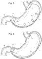
- a bariatric device 10 may have a single piece of Nitinol wire 11 which is shape set into a shape, but can be pulled under tension into a generally narrow and straight form, to allow for insertion of the device 10 through the esophagus.
- the elements may all be seamlessly integrated as one wire structure. See Figs. 1 and 2 .
- the shape set wire may impart an outwardly biasing force to the proximal and distal elements of the bariatric device 10 , which may vary during peristalsis.
- the connecting elements 25 may be constructed of materials, or in such a manner, that may impart an outwardly biasing force, to push on the cardiac and/or pyloric elements.
- Such outwardly biasing force may impart constant or intermittent pressure to various parts of the stomach, through the cardiac element 12 , the pyloric element 26 , the connecting elements 25 , or any combination thereof.
- the three elements may all be seamlessly integrated as one wire structure.
- tension to flex, compress or stretch the device 10 When tension to flex, compress or stretch the device 10 is released, it may coil into a ring or loop near the cardia 40 , and coil into a ring or loop near the pyloric region 42 , with a curved member to connect the two elements that is shaped to relatively match the greater curve 17 of the stomach.
- the curve could also match the lesser curve 16 of the stomach or both. See Figs. 3 and 4 .
- the connecting element 25 could curve into a single ring, or it could curve into a spiral. See Fig. 5 .
- the rings at each end could lock or not lock after forming, the rings may be closed, locked or continuous prior to placement down the esophagus, and could be compressed enough to fit within a placement tube for placement through the esophagus. See Figs. 3 and 4 .
- the elements of the bariatric device 10 may have a variety of shapes to add pressure points that continuously move to stimulate the cardiac region 40 during peristalsis. See Figs. 6 , 7, and 8 .
- the device 10 need not be fixed into place but may be moveable, and generally self-seating.
- the device 10 may have a bias to fit the nonsymmetrical stomach shape and ensure that it seats into the cardiac region 40 and pyloric region 42 .
- the action of peristalsis could create additional satiety signals as the device 10 moved in the stomach varying the pressure placed on the cardiac region 40 and/or the pyloric region 42 over time.
- the connecting element 25 connecting the two rings could follow the natural curve of the stomach to match the greater or lesser curve of the stomach 17 , 16 , or could have both. This would aid in the seating of the device 10 in the stomach after placement.
- the connecting element 25 could have one or more connecting members 30 connecting the cardiac and pyloric elements 12 , 26 . See Fig. 4 . However, these members 30 should be flexible enough to allow for natural peristalsis to occur, natural sphincter function to occur and to not cause erosion or irritation of the stomach wall or significant migration into the esophagus or duodenum 19 .
- the connecting element 25 could also be a spiral 28 or multiple spirals to create a flexible structure. See Fig. 5 .
- the connecting element 25 could also be bisected into two members that stack, telescope or articulate.
- the connecting element 25 could also have a joint such as a ball and socket type joint 29 or may be connected by magnets. See Fig. 9 .
- the rings 31 should be sized appropriately to ensure that they do not protrude or slip into the esophagus 32 or into the duodenum 19 , unless a variation of this embodiment/example is designed to have some portion of the device 10 enter those regions. This will allow the device 10 to apply pressure to the upper stomach or cardia 40 without fixation or sutures. The force against the pyloric region 42 and/or lower stomach will provide the counterforce against the upper stomach or cardia 40 .
- the force or contact against the pyloric region 42 and/or lower stomach may signal the body to stop eating.
- This force would mimic having a meal in the stomach with subsequent peristalsis, and sending the signal to stop eating.
- the multiple rings 31 could take the form of a spiral or could be separate rings 31 connected together. After reforming in the stomach, the rings 31 could lock, not lock, or be continuous. There are several ways that these elements could lock to form a ring.
- the cardiac element 12 would be to have a surface that contacts the upper stomach or cardia 40 such as a hemispherical or conical shaped shell 33 or balloon.
- the shape could also be asymmetrical but similar to a cone or hemisphere.
- This could be a thin walled element and could contain a lumen, no lumen, or a valve through which food could pass.
- Fig. 11 shows a valve 35 created by punching multiple crossing slits in an angular pattern through a thin walled membrane. In the case where there is no opening, the food would have to pass over the hemisphere or cone 33 which would have adequate flexibility to allow the food to pass into the stomach.
- restriction elements may require the esophagus 32 to work harder to pass the food over the element and could better stimulate the stretch receptors in the stomach and indirectly in the esophagus.
- the hemispherical shell 33 could have multiple grooves or channels to aid in allowing food to pass.
- it could be open or it could have a valve 35 that requires some force to allow food to pass through.
- An option could also be to have an esophageal member 36 that extends into the esophagus 32 for additional esophageal stimulation.
- This esophageal member 36 could be tethered by a thin structural member to support the esophageal member 36 , but not prevent the esophageal sphincter from closing. As mentioned above, this may require the esophagus 32 to work harder to pass the food and may better stimulate the stretch receptors in the stomach and indirectly in the esophagus.
- This esophageal member 36 could be a large tube, a small tube, a ring, a small sphere, multiple small spheres, or other suitable shapes.
- the pyloric element 26 could contain a restriction element, such as a lumen or a valve similar to the valve 35 shown in Fig. 11 for the cardiac element 12 .
- This restriction element could reduce the speed of food passing through the pyloric element 26 if desired.
- This valve 35 could be a thin membrane of silicone with a single or multiple slits punch through the center, or other types of valves could be used. See Fig. 12 .
- the membrane could also be the shape of funnel with a slit or circular opening, and made from elastomeric material to allow the funnel to expand open as food passes through.
- This drawing shows a pyloric element 26 with a valve 35 passing across the midsection of the pyloric element to slow down the passage of food.
- This drawing also describes a connecting element that could be comprised of an inflatable balloon 104 .
- This inflatable body could be compressed for placement and then inflated with a fluid or expandable foam or both to provide structure and adjustability after placement in the stomach.
- Another alternative embodiment/example for the pyloric element 26 would be to change the orientation to allow the axis of the loop or ring in Fig. 11 to be perpendicular to the axis of the pyloric valve 18 as shown in Fig. 14 and 15 .. This may simplify manufacturing construction yet perform the same function.
- the pyloric element 26 could have the loop in a single plane, two crossed planes, or multiple planes.
- Fig. 13A depicts a stomach cross-section showing the Z line and gastroesophageal ("GE") junction 38, the cardia or cardiac region 40 , the fundus 41 , the pyloric region which includes the pyloric antrum 42 , the pyloric valve 18 , and the duodenum 19 .
- Fig. 13B depicts the stomach's lesser curve 16 and greater curve 17 .
- Figs. 13A and 13B respectively show a representation of the stomach profile when the stomach is at rest and when the stomach is fully contracted during peristalsis and the change in stomach diameter and length. Due to the change in stomach profile, it may be advantageous to have a design that can flex to change with the stomach profile to allow the design to slide or translate along the greater curve 17 or flex as needed, but maintain the relative position of the cardiac element 12 .
- Figs. 14 and 15 show an alternate example of the design to adapt to stomach profile changes.
- Fig. 14 it shows the cardiac element 12 engaging the upper stomach region while the connecting element 25 is a spring with two closed loops 44 at each end which can compress and flex to accommodate peristalsis within the stomach.
- Fig. 15 shows these loops 44 compressing during peristalsis to allow the device 10 to maintain its relative position in the stomach and preventing it from migrating past the pyloric valve 18 .
- Another variation of this example would be to leave the loops open and allowed to flex until closed.
- Another variation would be to keep the loops closed, but include a mechanical stop inside the loop next to where the loop is closed to set a maximum amount that the device can flex.
- the connecting element 25 may be made up of two or more members 30 . See Figs. 16A and 16B . As shown in the drawing, the cardiac element 12 would contact the upper stomach or cardiac region 40 , while pyloric element 26 contacts the lower stomach or pyloric region 42 .
- the connecting element 25 has three members 30 , which are shown as curved wires or ribbons. One member 30 curves to match the lesser curve 16 (LC), while two other members 30 curve to match a median line between the lesser and greater curve 17 (GC), and curve to contact the anterior and proximal surfaces of the stomach to maintain its position even during peristalsis.
- LC lesser curve 16
- GC median line between the lesser and greater curve 17
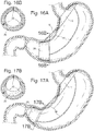
- FIG. 16A shows an optional location for the pyloric element 26 in the pyloric region 42 .
- Figs. 17A and 17B shows a similar example with another optional location for the pyloric element 26 closer to the pyloric valve 18 .
- the pyloric element is not intended to contact or block the opening of the pyloric valve.
- peristaltic motion may cause the device 10 to move inside the stomach and could cause the pyloric element 26 to slide from the relative locations such as those shown in Figs. 18A, 18B and 19 .
- FIGs. 18A, 18B and 19 depict a similar embodiment to Figs. 17A and 17B , but with an additional element to match the greater curve 17 .
- the greater curve 17 will shorten, and the member 30 that matches the greater curve could flex inward to a convex form.
- the member 30 may spring back to its original concave form.
- additional members 30 for the connecting element 25 may be used beyond the three and four members 30 described here, and could be located in a variety of locations along the midline, lesser curve 16 or greater curve 17 or any combination.
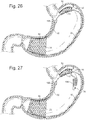
- Figs. 20A and 20B depict an example where the cardiac element 12 may be allowed to intermittently contact the upper stomach during peristalsis.
- the pyloric element may be a rigid or semi-rigid ring 49 and the connecting element 25 may be a spring to connect to the cardiac element 12 .
- this ring is curved and smoothed to reduce the potential for irritation.
- the ring 49 could engage the lower stomach at a fixed diameter when the stomach is at rest. Compression of the stomach during peristalsis would push the ring 49 towards the upper stomach to allow the cardiac element 12 to intermittently contact the upper stomach and/or cardiac area 40 . This may be advantageous to prevent overstimulation of the upper stomach or for other purposes.
- the bariatric device 10 may be self expanding.
- the self expanding portion could be made of Nitinol, silicone, polyurethane, Teflons, stainless steel, super alloys, or other suitable materials or combinations of suitable materials.
- the Nitinol wire may act as a stiffening member within the cardiac and pyloric elements 12, 26.
- the Nitinol wire could be arranged in many different patterns to allow for the appropriate amount of self expansion while allowing the element to compress during peristalsis.
- the array pattern could include circular arrays, angular arrays, linear arrays, or other suitable arrays.
- the pattern could be woven or a continuous spiral.
- the self expanding function may also assist in deployment by allowing the device 10 to compress and then regain its shape.
- a preferred method of deployment is to compress the bariatric device 10 into a long narrow shape, which is then placed in a deployment tube, sheath or catheter. The collapsed and encased device 10 is then guided down the patient's esophagus 32 and into the stomach, where the bariatric device 10 is released from the deployment tube or catheter. Once released, the device 10 would expand to its original operational shape.
- the stiffening member such as Nitinol wire, may provide adequate stiffness to expand the elements into their operational shape, and maintain that general shape during operation, while allowing flexibility to accommodate peristalsis.
- Figs. 21A and 21B show the cardiac and pyloric elements 12, 26 connected by a connecting element 25 with multiple curved members, which are shown to be a Nitinol wire mesh array 50 , but could be made of Nitinol wire, silicone, teflon, another suitable material, or a combination of these materials.
- the four members of the connecting element 25 have different lengths to allow for proper alignment and seating within the stomach.
- Fig. 21B depicts how during peristalsis, the stomach will contract and its profile will reduce.
- the bariatric device 10 may shift and flex within the stomach, but the self expansion feature allows it to spring open and maintain its general position correctly.
- the connecting element 25 could have a pre-curved bend to form a living hinge to direct where the element should flex during peristalsis as shown in 21B.
- an embodiment of the cardiac element 12 may comprise a portion of a substantially flattened frusto-conical shape which is adapted to fit the cardia proximal to the esophageal/cardiac opening of a stomach.
- the cardiac element could also be a portion of a tube or it could be a flat panel, portion of an ovoid, ellipsoid, sphere or other shape.
- Fig. 22 also shows that a preferred embodiment of the pyloric element 26 may be a steep frusto-conical shape, or a tapered cylinder, which is adapted to fit the pyloric region 42 of the stomach, and preferably sized so that it does not migrate past the pyloric valve 18 .
- these elements may have a wide variety of shapes or may be inflatable, and these are only examples.
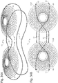
- the four connecting members may be constructed from 2 full loops or 2 loops connected together to create a " figure 8 " structure.
- the loops could be contoured to generally follow the curves of the stomach, and could be connected to the pyloric and cardiac elements 26, 12 in a variety of locations.
- the loops could be oriented to intersect at a variety of locations to provide different configurations with varying structural resistance and flexure points.
- Figs. 23A and 23B depict a bariatric device 10 where there are 2 separate closed loops 51 and the loops 51 are crossed in the pyloric element 26 so that the wires do not obstruct the distal opening of the element.
- the loops 51 are then aligned in a parallel pattern where they are attached to the cardiac element 12 .
- the 2 loops 52 are connected in a " Figure 8 " pattern where the loops are 52 crossed in the pyloric element 26 and do not obstruct the distal opening of the pyloric element 26 . See Figs. 24A and 24B The loops 52 cross again just below the opening of the cardiac element 12 , which allows the cardiac element 12 to flare more when the device 10 is laid flat and the loops 52 are compressed together such as would be the case inside the stomach. This could allow for more focused, linear contact of the cardiac element 12 with the cardia 40 and adjacent fundus 41 in the stomach. The cross of the loops 52 below the cardiac element 12 would provide more structural strength of the device 10 just below the GE junction 38 for more acute response.
- connecting element loops may be joined together by a means of fixation to hold them together. These could be held together by adhesive or a separate joint connection 105 .
- the shape of the joint connection could follow the shape of the connecting element or it could be a portion of a frusto-cone or other.
- a stiffening member such as a wire loop or other could be added cardiac element 12 to direct stiffness in a desired area.
- Figs. 25A and 25B show one possible orientation for a stiffening member, but other orientations, shapes and additional members could be added to generate a specific response.
- Figs. 25A and 25B also show a cardiac element with 2 members, the first member being proximal and the second member being distal to apply pressure in these focused areas. These members are shown as portions of a frusto-cone, but could be different shapes. Similarly, these members of the cardiac element could also be oriented in different locations.
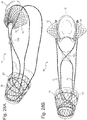
- FIG. 26 shows a side view of an embodiment with the inflatable member 76 .
- This member could have an inflation element, which could be a self sealing septum, valve or self sealing membrane on the surface of the inflatable member itself.
- the inflation element is not shown, but could be located near the pyloric element for ease of access, but could also be located at different sites.
- Fig. 27 shows a variation of the inflation element where the valve 74 is attached to the cardiac element by a retractable inflation tube 106 .
- the retractable inflation tube 106 may be constructed of a coiled tube, which may be may be contained in a housing.
- the retractable inflation tube 106 may be attached to a separate leash or tether.
- the valve 74 can be grasped inside the stomach using a standard grasper or snare, and then pulled up the esophagus for access outside the body while maintaining the device inside the stomach.
- the inflation element may be a slit valve that can be accessed by a blunt needle or small diameter instrument to push through the valve to allow fluid to be added or removed. After the appropriate volume of fluid has been added, the retractable inflation tube 106 can then be placed back into the stomach.
- the retractable inflation tube 106 would be designed so that it would not pass through the pylorus.
- Figs. 28A and 28B show a front and back side view of the inflatable member 76 in an inflated state.
- Figs. 29 , 30A, and 30B show a configuration where the connecting loop elements form a figure 8 , and the cardiac element 12 is constructed from a wireform similar to the stiffening member.
- the stiffening member could be in a variety of other orientations, shapes or patterns, and additional members could be added to engage specific areas of the stomach to generate a specific response.
- This element could also be adjustable in length, width, curvature or shape to generate a specific response.
- FIGs. 31A and 31B show an embodiment where connecting loop elements form a figure 8 , and the pyloric element is constructed by the 2 connecting loops crossing with connecting element joints 105 .
- the crossed connecting elements would engage the lower stomach to provide adequate resistance from passing the pylorus while maintaining pressure against the upper stomach. Additional loops could be added to the pyloric element or cardiac element to create a variety of profiles.
- Figs. 32 , 33A, and 33B show a cardiac element that is focused on the distal cardia. Similar to the other embodiments, this cardiac element may also contain a balloon to inflate to change the width of the device.
- the cardiac and pyloric element may have substantially the same shape. See Figs 34A, 34B , 34C, 34D and 35 . These figures show a device where the both elements are self-expanding flattened frusto-cones. Since the proximal and distal portions are the same, the device is symmetrically arranged on the connecting element and can be placed in either orientation. In another variation, the device may not be symmetrically arranged. In the symmetrical embodiment, the device can migrate out of position and/or rotate, and then re-seat with peristalsis without concern of regaining the proper orientation. As shown in Figs.
- the device may fold to create a wavy structure. Because the structure is wide, the device may sit higher in the lower stomach, above and adjacent to the proximal antrum and the incisura angularis. It may also sit at the proximal antrum. During peristalsis, the device 10 may move in the stomach, but may come to rest near the proximal antrum when the stomach is at rest or it may sit lower.
- the connecting elements used in this embodiment have the same profile for the proximal and distal portions which have a wide profile and may prevent the distal portion from seating low near the pyloric valve or contacting the pyloric valve.
- This folded structure may act as a restriction element, creating a tortuous path or a valve for chyme to pass through prior to passing through to the area adjacent to the pylorus and through the pyloric valve.
- the restriction element may aid in slowing gastric emptying and increase a feeling of satiety.
- These shapes could be could be a ring, a disk, a portion of a cone, portion of frusto-cone, a sphere, a portion of a sphere, an oval, an ovoid, a tear drop, a pyramid, a square, a rectangle, a trapezoid, a wireform, a spiral, a preformed wavy shape, multiple protuberances, multiple spheres or multiples of any shape or other suitable shapes. It could also be any other shapes previously described. These shapes could fold and change form once placed into the stomach to perform a different function such as slowing gastric emptying by creating a tortuous path. Similarly, the element could be preformed with folds or waves. Given that the cardiac and pyloric elements may have the same shape in certain embodiments, and/or may be interchangeable in position within the stomach, the claims may refer to them as a first element and a second element.
- These cardiac and pyloric elements may also contain a restriction element to slow gastric emptying.
- a restriction element could comprise an additional membrane or valve.
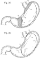
- Fig. 36 shows a device with a proximal and distal element that are hemispherical thin walled shells 33 .
- These restriction elements may comprise a valve 35 with multiple slits to reduce the flow of food through either element.
- a restriction element could also comprise a hole to allow for food to pass through or no lumen to allow food to pass around the elements as they flex or fold.
- Another variation of the restriction element to slow gastric emptying would be to have a thin walled flexible membrane, small protrusions, wire loops, or fingers that extend from the inner surface of the cardiac or pyloric elements.
- Figs. 37A and 37B shows the example of a device with a conical pyloric element with a thin walled flexible membrane 35 crossing through the center of the element.
- This membrane shows an oval opening, but the opening could be a slit, a hole or other shape.
- the pyloric element has a wide profile and may maintain its position near the proximal antrum and the incisura angularis.
- the device is not intended to directly contact the pyloric valve or pyloric opening. In other embodiments, however, the pyloric element may be sized to contact those areas.
- Figs. 37B, 37C, 37D, and 37F show other examples of a restriction element, which may include a reduced lumen, valve or tortuous path to reduce the flow of food through the pyloric element 26 .
- Figs. 37C and 37D show multiple flexible members 107 that extend from the internal surface of the pyloric element 26 to reduce the flow of food.
- Figs. 37E and 37F show multiple flexible members 107 that cross the internal surface at different heights to slow gastric emptying.
- the same structure as described above for the foldable pyloric element 26 may be combined with a different cardiac element 12 such as the wireform structure shown in Figs. 38A, 38B , 38C, and 38D This could combine unique features of the wireform to apply pressure at the cardia, while also using the folded design as a restriction element for slowing gastric emptying through the proximal antrum.
- a different cardiac element 12 such as the wireform structure shown in Figs. 38A, 38B , 38C, and 38D
- any combination of cardiac and pyloric elements disclosed herein can be used.
- the loops could be formed from Nitinol wire.
- the Nitinol wire used for the connecting elements or any elements in the device could be passivated to improve acid resistance. They could also be coated in an acid-resistant coating 53 such as silicone or silicone covering, PTFE, or other suitable coating, or not coated.
- These loops could also be made of spring steel, stainless steel, super alloys, teflons or other suitable materials or combinations of materials.
- the loops could be closed or connected in a variety of ways. For the example of Nitinol, the loops could be closed by a glue joint where the wire loop ends are glued inside of another tube.
- loops could also be closed by a crimping, swaging, welding or joined by a mechanical mechanism.
- the loops could also be left open, if a feature is added for adjustability and it is preferred to have the loops open with both ends fixed to the elements as needed.
- the contact members of the elements may be comprised of a variety of materials.
- the Nitinol wire pattern of the cardiac, pyloric, and or connecting elements 12, 26, 25, may be exposed for direct contact with the stomach or the wire could be covered or sealed in another material, such as silicone, PTFE, polyurethane or other suitable materials.
- Fig.39A depicts a pyloric element 26 where the wire mesh 50 is covered in another material to create a smooth surface for the contact member 54 to facilitate sliding within the stomach.
- Fig. 39B shows the wire exposed to the stomach mucosa surface.
- the Nitinol may be treated with a surface finish, passivation or coating to improve its acid resistance within the stomach.
- the contact and stiffening members of the elements may be separate, entirely integrated, or both.
- a cardiac element 12 is made entirely of Nitinol wire
- the wire acts as both a contact member and a stiffening member.
- the silicone would act as both a stiffening and contact member.
- the Nitinol wire is embedded in another material such as silicone
- the Nitinol wire acts as a stiffening member and the silicone acts as a contact member.
- the Nitinol wire may be partially exposed and partially covered by the silicone (and/or on the interior of the element), in which case the Nitinol wire acts as both a stiffening and contact member.
- the combination of materials may act as a stiffening member.
- the contact member is silicone with Nitinol wire embedded
- the silicone may act in conjunction with the Nitinol to provide more stiffness than the Nitinol could achieve alone.
- stiffening and contact members may be apparent to those skilled in the art.
- a preferred device 10 has adjustability or adaptability to match any changes in the patient over time.
- a variation of the above embodiments would be to allow the device 10 to be adjustable via an adjustment element 60 .
- This adjustability could be in the length, shape, angle or stiffness of the cardiac, pyloric, and/or connecting elements 12, 26, 25.
- different sized devices could be manufactured and the device replaced with a different size.
- the bariatric device 10 could be adjustable to allow for adjustment at the time of placement or could be adjusted at a later time. This adjustability could be achieved by having a variable spring tension in one of the elements to allow the device 10 to extend, contract, or distort as needed. It could also be achieved by adding an expansion joint 75 in a member to elongate or compress as needed. This expansion could be a manual adjustment performed by the physician in the office through a gastroscopic procedure. This expansion could be achieved by various mechanisms, including but not limited to those operated by: rotating a threaded member, ratcheting backwards or forwards, a hydraulic mechanism, a pneumatic mechanism, a cam, a tension mechanism, a telescoping mechanism or other elongation or contraction mechanisms.
- the outer surface of the connecting element 25 is preferably smooth with rounded or gently angled edges to prevent irritation of the stomach during peristalsis, although sharp angles may be preferred in some applications.
- these elements could be encased in a sleeve or sheath that could be removed or remained fixed during the expansion. A sheath may not be required if the expansion joint 75 is designed with smooth contours on its own.
- the device 10 could also be adjusted by manual means inside the stomach by using a gastroscopic instrument to come into direct contact with the device 10 .
- the instrument could also act as a pusher or puller to activate a pulley mechanism or a clipping mechanism.
- the connecting element 25 could be a ratchet or strut with multiple positional features such as holes, grooves, teeth or wedging action.
- the device 10 could have a feature to engage the ratchet teeth or positional features such as a pin or clip or other. The instrument could retract the pin or compress the clip and then reposition this feature in the next available location.
- the members of the connecting element 25 could have multiple beads or spheres 62 that are captured by a cuff or ring retainer on the cardiac element 12 .
- An instrument could be used to expand the cuff to pull the bead through for positioning.
- the cuff could have a keyway retainer feature that allows the bead to only fit through a specific location and then lock into position where the beads connect to the wire or ribbon or tube.
- Figs. 40A, 40B, 40C and 40D shows several examples of compressible clips 65 acting as a "bead" or positional feature that could be used for adjustability.
- a retainer strap 63 of silicone could be bonded on both sides to create a narrow passageway 66 where the clip 65 could be placed in the compressed position, and then expand open after passing through the strap 63 to maintain its position.
- Several straps 63 could be bonded in a row to create several positional locations.
- Figs. 40B and 40D shows the clip 65 in is open, relaxed state, where 47C shows the clip 65 in a compressed state where it can pass through the retainer strap 63 .
- a locking ring to fix the location of the connecting elements 25 into the pyloric element 26 .
- the pyloric element 26 could have several positional features connected to it.
- the connecting element 25 could also have several positional features attached to it.
- a locking ring could be placed inside to hold the position of the elements together and to alter the length of the whole device 10 to be longer or shorter.
- the ring could be fixed to the pyloric element 26 and compressed to capture the positional features located along the connecting element 25 .
- an instrument could act as a screw driver to rotate a member to thread the two elements closer or farther apart.
- the instrument could also have a needle to inject fluid into an inflation element 74 .
- Such an element may be a self sealing membrane to increase or decrease the length, diameter or stiffness through positive displacement of an expandable body.
- the self sealing membrane could be an injection port or it could be a self sealing surface on the expandable body, or the entire expandable body could be comprised of a self sealing surface.
- the term inflation element 74 can also refer to an injection port or to an area on the expandable body with a self sealing membrane.
- the self sealing membrane could also be a self sealing valve which can be accessed by a blunt needle or tube to allow access to add or remove fluid.
- the valve could be attached directly to the expandable member or it could be attached by a tube.
- Fig. 41 shows an inflation element 74 fixed to the pyloric element 26 or the connecting element 25 .
- This valve or port could be connected by a fluidic path to an expandable body such as a sealed inflatable body inside of an expansion joint 75 such as a piston and cylinder.
- the valve could be accessed by an endoscopic instrument with a blunt end, while an injection port could be accessed by an endoscopic instrument with a non-coring needle where saline or other suitable fluid could be injected or removed from the port which would allow the inflatable body to expand or contract to control the length of expansion.
- the device 10 could contain one or more with a manifold set up to deliver fluid from the port to all of the expansion joints.
- the system could also have an expandable body such as a syringe type joint which would not require a sealed internal inflatable body.
- Figs. 26, 27 , 28A, and 28B show an embodiment, where an inflatable body could be located on the cardiac member.
- An inflatable body could also be placed on the pyloric element(s) to increase the length or diameter.
- An inflatable body could also be placed along the connecting element to change the profile of the device.
- An embodiment could contain one or more inflatable bodies at the cardiac, pyloric, or connecting elements or any combination of the above.
- Inflating fluid which could be saline, water, air, or other suitable substances, may be inserted or removed through the inflation element 74 to increase or decrease the size of the inflatable body 76 .
- the amount of contact and/or pressure imparted by the cardiac element 12 on the cardiac region 40 and/or the upper region of the stomach may be adjusted, either while the device 10 is in the stomach, or prior to placement.
- This balloon could cover the entire cardiac surface or could only cover portions of the cardiac surface to direct the inflation for a specific response.
- the device 10 could contain linear and radial inflatable bodies.
- a gastroscopic instrument could also deliver heat directly to an expandable body such as a heat expanding mechanism (such as one made of Nitinol) for expansion of a wax or wax-like expansion member.
- a heat expanding mechanism such as one made of Nitinol
- a Nitinol clip could clip into a positional location on a strut.
- the instrument could heat the clip to release and then reposition it into a different location, remove the heat and allow the clip to re-engage the positional feature to lock it into place.
- the instrument could also have an inflatable body or a balloon to allow for physical contact with the device 10 to disengage a feature for repositioning into another location.
- Magnetic actuation Another adjustment mechanism could use magnets. See Fig. 42 .
- the connecting element 25 could contain a thread with a magnetic nut 79 placed over it.
- the controller magnet 80 could be placed in close proximity to the implanted magnet to cause it to rotate. The rotation of the controller magnet 80 could create a magnetic field which would cause the internal magnet 79 to turn allowing it to advance and retreat along the threaded member 81 .
- the controller magnet 80 could either be external to the body or it could be placed on the end of a gastroscopic instrument for close proximity.
- the controller magnet could be a magnet or an electromagnet to increase the intensity of the field and to improve magnetic coupling to ensure actuation.
- the controller magnet 80 could also be multiple magnets to improve magnetic coupling.
- Another means of manually adjusting the length of the device 10 would be to have modular pieces that could attach or adhere to the cardiac or pyloric elements 12 , 26 .
- an additional frusto-cone could be placed over the pyloric element 26 to increase the length of the overall design.
- Several could be stacked together to create a variety of lengths. Stacking frusto-cones could also be distanced from one another with a balloon on either frusto-cone to increase the distance between the two.
- a variation of this embodiment would be to have an additional member that could be collapsible or compressible and inserted down the center of the pyloric element 26 . Once it passes the pyloric element distal surface, the modular element would expand and attach to the outer surface. Several modular elements could be stacked together to create a variety of lengths.
- An alternative embodiment could have an additional element that could also pass down the center of the pyloric element 26 and expand past the distal surface, but with a clip that would allow it to remain clipped to the inside surface.
- the attachment mechanism could be positionally based so that the element could be repositioned to several locations for a variety of lengths.
- the manual expansion mechanism could be adjusted remotely by an apparatus outside the body, and/or automated.
- the expansion could be achieved by a small motor that could be driven by an implanted power source or driven by a remote power source such as induction.
- Energy could also be supplied by an RF signal, kinetic energy, ultrasound, microwave, cryogenic temperatures, laser, light, or thermal power.
- Power could also be supplied by a battery or implantable power cells that utilize glucose or other means for fuel.
- the automated expansion could also be achieved by a pump, a syringe type plunger, a piezoelectric crystal, a bellows, a Nitinol motor, a pH responsive material that changes shape, thermal expansion of a gas, fluid or solid (example wax) expansion, magnet forces or any other type automated expansion or compression mechanism.
- the control for activating this mechanism could be a remote control using a radiofrequency signal which can pass through tissue.
- the remote control could also be achieved by magnetic fields, time varying magnetic fields, radio waves, temperature variation, external pressure, pressure during swallowing, pH of any frequency or any other type of remote control mechanism.
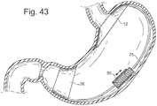
- the adjusting element could be connecting element, 25 entirely or partially comprised of a flexible, semi-flexible or rigid screw.
- a stepper motor 85 could be placed onto the flexible thread and could drive forward or back to allow the connecting element, 25 to draw together or push apart the elements. See Fig. 43 . These figures represent a threaded element that can be drawn together or apart.
- the adjusting element may require power to drive the motor 85 .
- the power could be supplied by an implanted power source such as a battery or it could be powered externally by induction through the coupling of an external antenna and an internal antenna.
- the antenna could be a simple ring at the top or bottom or obliquely on either element or it could be placed in the wall of the device 10 .
- the internal antenna could also be attached by a tether, free floating inside the esophagus, stomach or intestine. These could be made from materials to make them MRI compatible and/or MRI safe. This feature could be applied towards any actuation method where it is powered by induction.
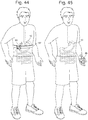
- an external hand held controller 86 may be required to transmit power for coupling. See Figs. 44 and 45 .
- the controller 86 could be set up to auto detect the internal antenna's presence and identify when coupling between the two antennas was adequate to allow for transmission and powering to take place, and to inform the user of function. This external controller 86 could then be used to display the distance that the stepper motor 85 had been advanced or retracted to allow the physician to control the adjustment. Similarly, the external controller 86 could be used for communication and control signals as an interface between the physician and the placed device 10 . This feature could be applied towards any actuation method powered by induction.
- An external antenna would be required for induction and could be placed into an external handheld controller 86 . This could be placed directly against or close to the patient's body at the height of the internal bariatric device 10 .
- the antenna could be housed with the other controller electronics in a single unit. This feature could be applied towards any actuation method powered by induction.
- Another alternative would be to have the external antenna in the form of a belt 87 that would wrap around the patients abdomen at the height of the device 10 to better align the antennas for improved coupling. This feature could be applied towards any actuation method powered by induction.
- the location of the actuation mechanism could also be inside any of the elements, or above or below any of them, or another location as would be best suited for the anatomy and function of the device 10 . This feature could be applied towards any actuation method. Actuation could be accomplished by allowing the screw to be pushed or pulled inside any of the elements to embed the adjustment mechanism internally to one of the other elements. Other actuations mechanisms such as those listed above or others could also be used for this adjustment.
- Induction could also be powered by an intragastric instrument.
- the instrument could have a flexible shaft that could fit through the mouth and down the esophagus or down the working channel of a gastroscope. Once the instrument was placed within or near the esophagus or stomach, it would allow the instrument to be in close proximity with the actuation mechanism in the device 10 .
- the end of the instrument could have antenna(e) to allow for inductive powering and/or communication with the actuation mechanism for adjustment. This feature could be applied towards any actuation method.
- the adjustment could also be achieved by a piezoelectric element or motor 85 . See Figs. 43 . These figures represent a threaded element that can be drawn together or apart.
- piezomotors there are several types that could be used for linear actuation.
- a motor from NewScale Technologies www.newscaletech.com
- the Squiggle Motor could be used which is very low profile and can be actuated when powered.
- Other motors or actuation mechanisms could also be used, and the Squiggle motor is just used as an example.
- the Squiggle motor could be attached to the connecting element, 25 to advance or retract the cardiac and/or the pyloric element 12 , 26 .
- the Squiggle motor could be placed in between any of the elements.
- more than one Squiggle motor could be placed at these locations.
- One of the advantages of a piezoelectric motor 85 is that it would allow the device 10 to be MRI compatible and safe.
- the piezoelectric motor 85 could be powered by an internal power source such as a battery or it could be powered by remote induction.
- the remote induction could be by a handheld external controller or it could be by a gastroscopic instrument placed down the esophagus. This motor could be encased in other materials to keep it dry and protected from the stomach environment.
- piezoelectric actuated motor 85 Another embodiment of a piezoelectric actuated motor 85 would be to have a rotating piezoelectric member that could thread along one or two threaded members similar to a worm gear.
- piezoelectric actuated motor 85 Another embodiment of a piezoelectric actuated motor 85 would be to have a piezoelectric crystal that elongates or flexes to actuate another member.
- All of the piezoelectric motors 85 may contain a sealed housing such as an expandable metal or plastic bellows to prevent moisture of fluid from contacting the piezoelectric elements.
- the connecting element could be a semi-flexible thread or rigid thread with a magnetic nut placed over it.
- Another strong magnet named a controller magnet 80 , could be placed in close proximity to the implanted magnet to cause it to rotate. The rotation of the controller magnet 80 could create a magnetic field which would cause the internal magnet to turn allowing it to advance and retract along the threaded member.
- the controller magnet 80 could either be external to the body or it could be placed on the end of a gastroscopic instrument for close proximity.
- the controller magnet 80 could be a magnet or an electromagnet to increase the intensity of the field and to improve magnetic coupling to ensure actuation.
- the controller magnet 80 could also be multiple magnets to improve magnetic coupling.
- the adjustment element could also be actuated by Nitinol or a substance with similar properties. When a current is passed through Nitinol, it heats and causes the Nitinol to change its shape. Nitinol can expand into a variety of different shapes.
- a linear actuator could be made from Nitinol to advance or retract along an actuation member.
- Heat could be generated from an implanted battery or it could be delivered by induction.
- the connecting element could have multiple positional features such as holes, grooves, teeth or a wedging feature.
- a Nitinol clip could have a feature to engage these positional features.
- the Nitinol clip could be heated to change shape to allow it to advance or retract into different positional features to increase or decrease the length.
- Nitinol actuations there are other Nitinol actuations that could be provided as well.
- Another adjustment mechanism could be by use of an ultrasound motor or one powered by external ultrasound. This could use external ultrasound equipment to send sonic waves into the body to actuate the motor. This would also provide an MRI compatible option without requiring an internal power source or induction.
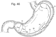
- the adjustment element 60 in Fig. 46 could also be actuated through hydraulic means for radial expansion or linear actuation as previously described.
- the cardiac or pyloric element 12 , 26 could be inflated with a fluid to increase the diameter or length of the device 10 to increase pressures against the upper stomach or cardia 40 , and pyloric region 42 . It could increase in volume by accessing a self sealing membrane such as a self sealing drug delivery port, self sealing membrane on the expandable body, or a self sealing valve attached to the device 10 .
- the inflation could be achieved by a piezoelectric pump, a peristaltic pump, a positive displacement pump or a syringe pump.
- Piezoelectric pump The pump could be comprised of a piezoelectric element which can flex to propel fluid directly or a member that could propel fluid.
- a piezoelectric disk could be captured in a housing with an incoming channel and an outgoing channel. The disk could be powered to cause it to flex into a dome shape to push fluid into the outgoing channel. A valve would be required to close the incoming channel to ensure directional flow to the outgoing channel.
- the piezoelectric Squiggle motor as described above could be used to linearly actuate a fluid up or down a tube to hydraulically actuate position.
- Stepper motor pump Actuation could be achieved by a stepper motor where the motor linearly actuates to compress a reservoir or syringe to move fluid within a tube or constrained volume.
- Wax expansion pump Fluid could also be propelled by a wax expansion mechanism. When wax is heated to melting it expands by approximately 30%. A solid plug of wax could be heated to expand and drive fluid through a valve to hydraulically actuate lengthening. The lengthening structure could be made to move only in one direction, so that when the wax cools it will not contract. The wax expansion could also be used to actuate other adjustment mechanisms.
- Peristaltic pump The members could also be driven by a peristaltic pump.
- the external diameter of a cylindrical actuator could be used to compress a length of tubing to create an occlusion.
- the cylindrical actuator could be rotated along the tube to drive fluid forward or backwards inside the tube.
- the peristaltic pump could also be actuated by a stepper motor or by a piezoelectric element or other.
- Gas expansion / propellant pump The length could also be actuated by a gas expansion pump where a gas like Freon or others could be used to expand when exposed to a higher temperature. Similar principles to the devices like the Codman pump could be used. This change in volume could drive the pump forward. Similarly, there could be compressed gas constrained in a pressure vessel with a valve. The valve could be remotely activated to allow gas to propel a syringe, fluid or to compress a constrained volume.
- Positive displacement pump There are implant grade positive displacement pumps that are available on the market for drug delivery that could be used to displace a specific amount of fluid for hydraulic inflation of the adjustment element 60 .
- Syringe pump A syringe pump could be made by advancing fluid through a syringe.
- the syringe could be actuated by a stepper motor, a piezoelectric actuator, a magnet or by a Nitinol actuator as described above.
- the adjustment element could also be inflated by use of a hydrogel to absorb fluids and could be actuated by changes in temperature, pH or tonicity to change shape or volume
- Hypertonic fluid the adjustment element 60 could also be inflated by using a hypertonic fluid in the inflation area and allowing it to absorb fluid across a semi permeable membrane.
- the device 10 could change diameter by various actuation mechanisms. All of the above-described mechanisms could also be adapted for use for a diametric change instead of a linear change.
- the device 10 could have a sensor 88 that could sense a parameter such as pressure, motion, peristalsis, tension, pH, temperature, chemical or other appropriate parameters, or various parameter combinations.
- the sensor 88 could output a signal to be used by an actuation element to actuate an adjustment element, to a memory element such as a microchip, or be read by a remote reader or remote controller.
- Sensors 88 could be used to gather important patient data to understand performance, patient status or whether an adjustment needs to be performed. For ease of use and compatibility with the body, wireless sensors would be preferred.
- the sensors 88 could be direct tissue contact, intermittent patient contact or could monitor the intraluminal pressure inside GI tract. The data could be used for no other reason than to just monitor patient status.
- Fig. 46 depicts sensors 88 , which could be embedded in any of the elements or it could be tethered to any of the elements to allow it to be suspended inside the GI tract. Based on the sensed parameter, the device 10 could be adjusted. The adjustment could have an open or closed loop system increasing or decreasing the applied force, pressure or sensed parameter.
- the sensed parameter could detect whether the device 10 was not at an ideal condition, and could then send a signal to a control mechanism for automatically adjusting the system.
- This mechanism could be under physician control (open system) or without physician control (closed system).
- the adjustment could also be a manual adjustment where the parameters are being monitored to guide the adjustment. It could also control the shape of the cardiac, pyloric, and/or connecting elements 12, 26, 25 to vary stiffness, size, length, form or shape.
- the sensor 88 could sense a parameter and then adjust the device 10 as needed to bring the sensed parameter into the ideal range. There could be an algorithm that controls the ideal parameter or it could be based on a parameter range.
- the device 10 would be adjustable to meet the needs of the patient.
- the physician would have control of when the device 10 would adjust.
- the device could have it owns internal power source or the device 10 could be passive and only inductively powered when in close proximity to an external controller under the supervision of a physician.
- the physician could have a remote controller with the ability of powering the device 10 inductively, and then begin to monitor the sensors feedback signals to see physical parameters of the patient at baseline such as pressure of the device 10 against the cardia.
- the sensor monitoring could also be performed while the patient is eating or drinking, or not eating or drinking. As the patient consumes, the esophageal and stomach peristaltic waves will increase in intensity as they propel the food or drink from the mouth to the stomach.
- a sensor 88 could detect when these waves increase in amplitude, frequency, and pressure.
- the parameter could read on the external controller by the physician, and then the physician could send a signal to the automated expansion mechanism in the device 10 to adjust the device.
- the physician could then query the sensor 88 again to determine whether the device 10 was in the ideal settings and whether the pressure against the cardia or sensed parameter was optimized.
- the physician could iteratively control the amount of adjustment and monitor the parameters until the ideal condition was met. Where the device has its own power source, the physician may still have the control to wake up the device, query the sensors and then adjust the device as described above. The only difference would be that the device was powered by the power source and not require inductive power from outside.
- the physician could read the parameter signals while under his supervision, but have the sensors 88 send a signal directly to the automated expansion mechanism to adjust until the device 10 was within the ideal parameters.
- the data collected could be analyzed by the controller for averages, minimums, maximums and standard deviations over time and use an algorithm to determine the ideal settings.
- the controller could then monitor and adjust on its own until the ideal conditions were met, but while the physician was present to verify all conditions and verify patient acceptance.
- the device 10 In a closed loop system, the device 10 would be active with its own integrated power source. The device 10 could wake up at routine intervals to monitor or could monitor all the time. The data collected could be analyzed for averages, minimums, maximums and standard deviations over time and use an algorithm to determine the ideal settings. As the patient begins to consume food or drink, the device sensors 88 would detect the sensed parameter and signal the automated expansion/contraction mechanism to adjust the device 10 as needed. In this embodiment, the device 10 could be fully automated and would not require intervention from an outside individual.
- the device 10 there could be multiple sensors 88 on the device 10 to determine the pressure or force areas, or other sensed parameters on the device 10 and where it needs to be varied to meet the ideal conditions for the stomach.
- the connecting element 25 has multiple components, this could be used to align the device 10 in the stomach to provide a custom fit for each person.
- the sensor(s) 88 could have a built in power source or it could have a remote power source such as induction so that it would only wake up and activate when an external controller was brought near.
- the device 10 could have integrated memory to allow storage of patient and device 10 data.
- the active device there could be 24 hour data recording of key parameters or there could be data collected at key intervals throughout the day to detect when the patient is eating and whether they are being compliant with their eating. It could record weight tracking, BMI or other data as needed which could be queried by an external controller.
- This data could also be downloaded into a physician's patient tracking database for ease of patient tracking. Similarly, this data could be downloaded and tracked on an internet tracking website, where the patient could log on and see their history and progress. The patient could add information to the website such as weight or an eating log, adverse events or other conditions that the physician or patient would like to track.
- the physician could choose to collect and record data as needed at the time of the adjustment such as weight, date, time, and adjustment amount or other.
- the device 10 could be adapted to allow for remote adjustments over the phone. This would be especially advantageous for patients living in rural areas where they are far from their physician's office. It could also be for convenience of having an adjustment without having to travel to the physician's office. This would allow a physician to discuss the patient's progress with the patient directly and then query the device sensor 88 to see how the device performance is. Based on the feedback of the device 10 , the physician could then adjust the patient.
- the device 10 could have an emitter element for dispensing a drug, hormone or bioactive agent to further induce satiety, weight management or other disease management such as diabetes.
- the drug could be a weight management drug currently on the market or one to be developed. Similarly, it could be a satiety hormone or other bioactive agent. In the published literature, there is a growing mass of information on satiety hormones.
- the bioactive agent could be applied by the emitter element through a drug eluting coating, a reservoir with a pump, or a permeable membrane placed on the device 10 where the drugs could pass from the device 10 into the gut.
- the emitter element could release such substances in response to a signal from a sensor 88 , a timed basis, or other release criteria.
- the device 10 could have a tube that trails into the intestines to allow the drug to be delivered downstream where the pH is higher and would not destroy the bioactive agent.
- the device 10 could have a surface finish or macrotexture for gripping the stomach. If the device 10 could grip the inner mucosa of the stomach, it could elongate or expand to further stretch the stomach in key areas to induce further satiety as needed.
- the cardiac element 12 could be a conical spiral with a surface texture that lightly grips the mucosa and or stomach musculature. If the spiral were made of Nitinol or other temperature-sensitive substance, the device 10 could expand the spiral by a variation of temperature. By applying a temperature variation, such as by drinking a hot liquid or otherwise, the device 10 could expand and cause a satiety response.
- the surface could be multiple protuberances, barbs, a rough bead blast, or other finishes suitable for gripping the stomach wall.
- the device 10 could have a thin flexible tube 89 attached to the pyloric element 26 that could trail into the duodenum 19 to act as a barrier to food absorption. See Fig. 47 .
- This tube 89 would be of similar diameter to the duodenum 19 and all food passing through the pyloric element 26 would pass directly into this sleeve. Similar to the rerouting performed in a gastric bypass or Roux en Y bypass, the sleeve 89 would be approximately 100cm long, but could be longer or shorter depending on the amount of malabsorption required.
- This tube 89 may be made of an acid resistant material such as Teflon, PTFE, ePTFE, FEP, silicone, elastomers or other acid resistant materials.
- the device 10 could incorporate electrical stimulation to the stomach musculature, stomach nerves or the vagus to further improve satiety stimulation and weight loss.
- Energy used for this stimulation could be RF, ultrasound, microwave cryogenic, laser, light, electrical, mechanical or thermal.
- the device 10 could have leads incorporated that could embed into the stomach wall or be surgically placed around a nerve, or the stimulation could be applied directly through surface contact of the device 10 to the stomach mucosa.
- the bariatric device 10 may have an adjustment element 60 that is equipped with a temporary expansion/contraction element that may allow for temporary adjustment based on activation of a material property, sensor 88 or mechanism of the device 10 .
- a temporary expansion/contraction element may allow for temporary adjustment based on activation of a material property, sensor 88 or mechanism of the device 10 .
- the temporary expansion/contraction element may adjust only upon eating, and then retract after eating.
- the device 10 may be desirable for the device 10 to adjust with the pH cycle of the patient where pH will be higher prior to eating and then lower after eating. This would allow for intermittent stimulation of the stretch receptors to avoid receptor fatigue over time.
- the material could be heat sensitive using materials such as Nitinol, which could expand after consuming a hot liquid.
- the device 10 could have a sensor 88 or material that is pH or glucose sensitive or detect the presence of food, which could activate the temporary expansion/contraction element to expand when a certain threshold for pH has been reached or glucose or fat is present after eating.
- this temporary expansion/contraction element could be activated by a magnetic field such as swallowing a magnetic pill that could temporarily expand the device 10 .
- the magnetic pill would be small enough and shaped appropriately for passage through the gastrointestinal tract, and biocompatible.
- the patient could consume the electromagnetic oill when a satiety signal was desired. It may also be desirable for the device 10 to adjust based on time or sleep cycle such that the device 10 adjusts at specific times of the day or when the patient lays horizontal. Other parameters or mechanisms to trigger the temporary expansion could be used.
- a tube, catheter, or sheath may be required to protect the anatomy during placement of the device 10 down the esophagus and into the stomach. It could be a simple flexible tube such as silicone or urethane tube to aid in straightening and compressing the device 10 while it is being introduced. Insertion of the device 10 into the tube would require compression of the device 10 into a narrow, insertable shape.
- a standard gastroscopic tool could be used to push or pull the device 10 down the tube.
- a custom gastroscopic tool or sheath could be used to introduce the device 10 into the stomach through the esophagus or other narrow opening.
- a flexible tube such as a standard overtube could be used with a standard or custom endoscopic tool.
- the tube may be placed down the esophagus and the tool then placed down the lumen of the overtube.
- a standard tool such as a grasper or snare could grasp the device 10 and pull it up the tube.
- the device 10 would be straightened by the overtube for removal from the stomach and esophagus.
- the elements may incorporate a collapsing mechanism designed to collapse the element into a compact shape for removal.
- a constriction member comprising a wire or thread sewn spirally around, through, or inside the length of the element. When the constriction member is pulled, it tightens the circumference of the pyloric element like a drawstring, which collapses the element down to a narrow profile that can be safely removed through the esophagus or other narrow opening, or ease its placement into a tube for removal.
- Similar collapsing mechanisms can be installed in the cardiac, and/or connecting elements 12, 25 .
- the constriction member could be made from Nitinol, stainless steel wire, ptfe thread, eptfe thread or ptfe coated threads or other suitable materials.
- the constriction member could be integrated into the elements in a variety of patterns such as a continuous spiral, two spirals of reversing orientation, or other.
- connection of the cardiac, pyloric and connecting element may be equipped with a release element, which would allow the cardiac, pyloric and/or connecting elements to be releasable, cut-able or modular, as to allow the device to be disassembled into components for ease of removal.
- Figs. 48, 49A and 49B show a release element in the form of a releasable clip 108 in the closed and open positions.
- the clip could be made of an elastomer or polymer or other, but would need adequate flexibility to allow the clip to close and then re-open.
- the clip has a locking tooth 109 which compresses when pulled through a narrow channel 110 , and then expands into an opening to lock the clip into position.
- Fig. 48 shows as side view of the releasable clip in the locked position in a suggested location to attach a connecting element to another element.
- a release element like this could be bonded or incorporated into the cardiac and pyloric elements and then could be locked around the connecting element to secure the assembly.
- standard instruments could be used as a releasing tool under the visualization of a gastroscope to release the tabs to disassemble the pyloric 26 and/or cardiac element 12 from the connecting elements 25 . Then each element or combination of elements could then be removed up the esophagus or through an over tube.
- the pyloric or cardiac elements could still contain a collapsing member to further collapse the element for removal.
- the connections could be placed over a single section of the connecting element or it could be placed over a joint to join two connecting elements.
- the connection length could be a short distance or it could be a relatively long distance. With a short distance, several clips could be used to join a connecting element to a cardiac or pyloric element such as shown in Fig. 50A . With a long element, one clip could feasibly connect the two elements such as shown in Fig 50B.
- Figs. 50A and 50B show an example of release elements where the modular clips could be used to connect the cardiac, pyloric and connecting elements, 12, 25, 26 . These are only examples of where a connection could be located, but other locations could be used. Similarly, this modular clip only shows one type of clip, but several other options could be used.
- the modular connection of the components could be equipped with release elements comprising many different mechanisms such as other clip designs, ties and could also provide an area where the connection is to be cut by a releasing tool, such as endoscopic scissors or electro-cauterizer, or other custom tools.
- the connecting elements could be sewn into the pyloric and cardiac elements with acid resistant thread such as ePTFE thread and/or cloth.
- the thread or cloth could be cut by a releasing tool such as surgical scissors or an electro-cauterizer for removal.
- the connection could be made of many different materials such as silicone, nitinol, polymers, super alloys, or other suitable materials that can withstand the acidic environment of the stomach.
- the releasing tool could be many different endoscopic instruments.
- This invention may be industrially applied to the development, manufacture, and use of bariatric devices for weight loss purposes.
Claims (12)
- Dispositif bariatrique (10) pour placement dans un estomac afin d'obtenir une perte de poids, comprenant :a. un premier élément (12) qui est à même de s'engager sur l'estomac supérieur,b. un second élément (26) avec un premier élément de restriction (35 ; 49 ; 107) etc. un élément de raccordement (25) couplant le premier élément (12) et le second élément (26),caractérisé en ce que :l'élément de raccordement (25) inclut une pluralité d'éléments de raccordement (30) s'étendant chacun du premier élément (12) au second élément (26),la pluralité d'éléments de raccordement (30) inclut au moins un premier élément de raccordement (30) et un second élément de raccordement (30) et en ce quele premier élément de raccordement (30) est conçu pour s'étendre le long de la plus petite courbe (16) de l'estomac et le second élément de raccordement (30) est conçu pour s'étendre le long de la plus grande courbe (17) de l'estomac.
- Dispositif bariatrique (10) selon la revendication 1, dans lequel l'élément de raccordement (25) est conçu pour communiquer une force de sollicitation vers l'extérieur contre à la fois le premier élément (12) et le second élément (26).
- Dispositif bariatrique (10) pour placement dans un estomac afin d'obtenir une perte de poids selon la revendication 1, dans lequel le premier élément (12) est équipé d'un second élément de restriction (35).
- Dispositif bariatrique (10) pour placement dans un estomac afin d'obtenir une perte de poids selon la revendication 2, dans lequel le premier élément (12) et le second élément (26) ont sensiblement la même forme.
- Dispositif bariatrique (10) pour placement dans un estomac afin d'obtenir une perte de poids selon la revendication 1, dans lequel le second élément (26) est calibré pour s'ajuster de manière proximale et adjacente à la région pylorique (42) ou dans lequel le second élément (26) est calibré pour s'ajuster à la région pylorique proximale (42).
- Dispositif bariatrique (10) pour placement dans un estomac afin d'obtenir une perte de poids selon la revendication 1, dans lequel le second élément (26) est calibré et conçu de sorte qu'il ne vienne pas en contact avec la valvule pylorique (18).
- Dispositif bariatrique (10) selon l'une quelconque des revendications 1 à 6, dans lequel le premier élément (12) est un élément cardiaque (12) et le second élément (26) est un élément pylorique (26).
- Dispositif bariatrique (10) selon la revendication 1, dans lequel le premier élément (12), l'élément de raccordement (25) et le second élément (26) sont constitués d'un matériau élastique à retenue de forme.
- Dispositif bariatrique (10) selon la revendication 2, comprenant en outre un élément d'ajustement (60) pour ajuster la force de sollicitation vers l'extérieur tandis que le dispositif bariatrique (10) se trouve dans l'estomac.
- Dispositif bariatrique (10) selon la revendication 2, comprenant en outre :a. un élément d'ajustement (60) pour ajuster la force de sollicitation vers l'extérieur tandis que le dispositif bariatrique (10) se trouve dans l'estomac,b. un dispositif de commande à distance qui est séparé du dispositif bariatrique (10),c. un élément d'actionnement qui reçoit des signaux du dispositif de commande à distance, dans lequel l'élément d'actionnement actionne l'élément d'ajustement (60).
- Dispositif bariatrique (10) selon la revendication 1, dans lequel l'élément de raccordement (25) est constitué d'au moins un fil métallique incurvé.
- Dispositif bariatrique (10) selon la revendication 1, dans lequel le premier élément (12) comprend une structure en forme de fil métallique.
Applications Claiming Priority (6)
| Application Number | Priority Date | Filing Date | Title |
|---|---|---|---|
| US25381609P | 2009-10-21 | 2009-10-21 | |
| US26204509P | 2009-11-17 | 2009-11-17 | |
| US26204009P | 2009-11-17 | 2009-11-17 | |
| US26465109P | 2009-11-25 | 2009-11-25 | |
| PCT/US2010/041774 WO2011049651A1 (fr) | 2009-10-21 | 2010-07-13 | Dispositif bariatrique et méthode de perte de poids |
| PCT/US2010/053619 WO2011050208A1 (fr) | 2009-10-21 | 2010-10-21 | Dispositif bariatrique et procédé de perte de poids |
Publications (3)
| Publication Number | Publication Date |
|---|---|
| EP2490619A1 EP2490619A1 (fr) | 2012-08-29 |
| EP2490619A4 EP2490619A4 (fr) | 2013-10-30 |
| EP2490619B1 true EP2490619B1 (fr) | 2019-03-13 |
Family
ID=43900609
Family Applications (2)
| Application Number | Title | Priority Date | Filing Date |
|---|---|---|---|
| EP10825350.1A Active EP2490746B1 (fr) | 2009-10-21 | 2010-07-13 | Dispositif bariatrique de perte de poids |
| EP10825704.9A Active EP2490619B1 (fr) | 2009-10-21 | 2010-10-21 | Dispositif bariatrique de perte de poids |
Family Applications Before (1)
| Application Number | Title | Priority Date | Filing Date |
|---|---|---|---|
| EP10825350.1A Active EP2490746B1 (fr) | 2009-10-21 | 2010-07-13 | Dispositif bariatrique de perte de poids |
Country Status (5)
| Country | Link |
|---|---|
| US (4) | US9532892B2 (fr) |
| EP (2) | EP2490746B1 (fr) |
| AU (2) | AU2010308498B2 (fr) |
| CA (2) | CA2778590A1 (fr) |
| WO (2) | WO2011049651A1 (fr) |
Families Citing this family (28)
| Publication number | Priority date | Publication date | Assignee | Title |
|---|---|---|---|---|
| US10420665B2 (en) | 2010-06-13 | 2019-09-24 | W. L. Gore & Associates, Inc. | Intragastric device for treating obesity |
| US9526648B2 (en) | 2010-06-13 | 2016-12-27 | Synerz Medical, Inc. | Intragastric device for treating obesity |
| US8628554B2 (en) | 2010-06-13 | 2014-01-14 | Virender K. Sharma | Intragastric device for treating obesity |
| US10010439B2 (en) | 2010-06-13 | 2018-07-03 | Synerz Medical, Inc. | Intragastric device for treating obesity |
| EP2595693B1 (fr) * | 2010-07-22 | 2015-03-04 | Endobetix Ltd | Dispositif de déviation pancréatico-biliaire |
| US9463107B2 (en) | 2010-10-18 | 2016-10-11 | Apollo Endosurgery, Inc. | Variable size intragastric implant devices |
| WO2012054519A2 (fr) | 2010-10-18 | 2012-04-26 | Allergan, Inc. | Implants intra-gastriques réactifs |
| EP2629714B1 (fr) | 2010-10-18 | 2015-12-30 | Apollo Endosurgery, Inc. | Implants intra-gastriques pourvus de pièces d'ancrage duodénal |
| US8870966B2 (en) | 2010-10-18 | 2014-10-28 | Apollo Endosurgery, Inc. | Intragastric balloon for treating obesity |
| US8920447B2 (en) * | 2010-10-19 | 2014-12-30 | Apollo Endosurgery, Inc. | Articulated gastric implant clip |
| US20120095497A1 (en) * | 2010-10-19 | 2012-04-19 | Allergan, Inc. | Non-inflatable gastric implants and systems |
| ES2593753T3 (es) | 2010-10-19 | 2016-12-13 | Apollo Endosurgery, Inc. | Manga duodenal con anclaje sin perforación |
| US9398969B2 (en) | 2010-10-19 | 2016-07-26 | Apollo Endosurgery, Inc. | Upper stomach gastric implants |
| US8864840B2 (en) | 2010-10-19 | 2014-10-21 | Apollo Endosurgery, Inc. | Intragastric implants with collapsible frames |
| US9498365B2 (en) | 2010-10-19 | 2016-11-22 | Apollo Endosurgery, Inc. | Intragastric implants with multiple fluid chambers |
| US9198790B2 (en) | 2010-10-19 | 2015-12-01 | Apollo Endosurgery, Inc. | Upper stomach gastric implants |
| EP2741808B1 (fr) * | 2011-08-10 | 2017-03-22 | National University of Singapore | Système d'ancrage et de pose pour un implant gastroduodénal |
| US9456916B2 (en) | 2013-03-12 | 2016-10-04 | Medibotics Llc | Device for selectively reducing absorption of unhealthy food |
| US10137023B2 (en) | 2012-09-14 | 2018-11-27 | Medibotics Llc | Colonnade (TM) expandable intragastric food flow lumen device |
| US20140200591A1 (en) * | 2013-01-11 | 2014-07-17 | Hologic, Inc. | Cervical sealing apparatus |
| US9067070B2 (en) | 2013-03-12 | 2015-06-30 | Medibotics Llc | Dysgeusia-inducing neurostimulation for modifying consumption of a selected nutrient type |
| US9011365B2 (en) | 2013-03-12 | 2015-04-21 | Medibotics Llc | Adjustable gastrointestinal bifurcation (AGB) for reduced absorption of unhealthy food |
| US9265640B2 (en) | 2013-08-28 | 2016-02-23 | Ethicon Endo-Surgery, Inc. | Conforming anchor for duodenal barrier |
| CN107106284B (zh) * | 2014-12-29 | 2019-12-27 | Bfkw有限公司 | 管腔内装置的固定 |
| US20170007434A1 (en) * | 2015-07-10 | 2017-01-12 | Hamilton Scientific, Ltd. | Gi-endocrine drug delivery device and method of use |
| US10779980B2 (en) | 2016-04-27 | 2020-09-22 | Synerz Medical, Inc. | Intragastric device for treating obesity |
| CN106859721B (zh) * | 2017-01-12 | 2019-04-26 | 上海心瑞医疗科技有限公司 | 一种隔离装置预装载的介入系统 |
| CN106890016B (zh) * | 2017-01-12 | 2020-04-17 | 上海心瑞医疗科技有限公司 | 一种用于隔离装置的回收系统 |
Citations (1)
| Publication number | Priority date | Publication date | Assignee | Title |
|---|---|---|---|---|
| US20050228504A1 (en) * | 2004-03-26 | 2005-10-13 | Demarais Denise M | Systems and methods for treating obesity |
Family Cites Families (125)
| Publication number | Priority date | Publication date | Assignee | Title |
|---|---|---|---|---|
| US4899747A (en) | 1981-12-10 | 1990-02-13 | Garren Lloyd R | Method and appartus for treating obesity |
| US4416267A (en) | 1981-12-10 | 1983-11-22 | Garren Lloyd R | Method and apparatus for treating obesity |
| WO1988000027A1 (fr) | 1986-07-09 | 1988-01-14 | Angelchik Jean P | Procede pour le traitement de l'obesite morbide |
| US4607618A (en) | 1983-02-23 | 1986-08-26 | Angelchik Jean P | Method for treatment of morbid obesity |
| US4648383A (en) | 1985-01-11 | 1987-03-10 | Angelchik Jean P | Peroral apparatus for morbid obesity treatment |
| DE3516018A1 (de) | 1985-05-02 | 1986-12-18 | Holger 1000 Berlin Kruse | Tragbares geraet zur feststellung der magenfunktion auf der grundlage der magensaeure |
| US4739758A (en) | 1986-05-19 | 1988-04-26 | Criticare Systems, Inc. | Apparatus for stomach cavity reduction |
| US4844068A (en) | 1987-06-05 | 1989-07-04 | Ethicon, Inc. | Bariatric surgical instrument |
| US4925446A (en) | 1988-07-06 | 1990-05-15 | Transpharm Group Inc. | Removable inflatable intragastrointestinal device for delivering beneficial agents |
| SE465017B (sv) | 1989-11-24 | 1991-07-15 | Lars Knutson | Anordning foer segmentell perfusion/aspiration av grovtarmen |
| US5259399A (en) | 1992-03-02 | 1993-11-09 | Alan Brown | Device and method of causing weight loss using removable variable volume intragastric bladder |
| US5820584A (en) | 1997-08-28 | 1998-10-13 | Crabb; Jerry A. | Duodenal insert and method of use |
| US6740082B2 (en) | 1998-12-29 | 2004-05-25 | John H. Shadduck | Surgical instruments for treating gastro-esophageal reflux |
| US6264700B1 (en) | 1998-08-27 | 2001-07-24 | Endonetics, Inc. | Prosthetic gastroesophageal valve |
| WO2000032092A1 (fr) | 1998-11-25 | 2000-06-08 | Ball Semiconductor, Inc. | Systeme de surveillance intraluminaire |
| US6322538B1 (en) | 1999-02-18 | 2001-11-27 | Scimed Life Systems, Inc. | Gastro-intestinal tube placement device |
| MXPA00001922A (es) | 2000-02-24 | 2002-03-08 | De Hayos Garza Andres | Cateter de balon intragastrico percutaneo para tratamiento de la obesidad. |
| US6540789B1 (en) | 2000-06-15 | 2003-04-01 | Scimed Life Systems, Inc. | Method for treating morbid obesity |
| US7033373B2 (en) * | 2000-11-03 | 2006-04-25 | Satiety, Inc. | Method and device for use in minimally invasive placement of space-occupying intragastric devices |
| US6579301B1 (en) | 2000-11-17 | 2003-06-17 | Syntheon, Llc | Intragastric balloon device adapted to be repeatedly varied in volume without external assistance |
| ES2174749B1 (es) | 2001-02-12 | 2004-08-16 | Luis Miguel Molina Trigueros | Pinza gastrica para realizacion de gastroplastia vertical bandeada y by-pass gastrico a curvadura menor. |
| EP1366716B1 (fr) | 2001-03-09 | 2005-04-27 | José Rafael Garza Alvarez | Ensemble ballon intragastrique |
| US7616996B2 (en) | 2005-09-01 | 2009-11-10 | Intrapace, Inc. | Randomized stimulation of a gastrointestinal organ |
| US6558400B2 (en) | 2001-05-30 | 2003-05-06 | Satiety, Inc. | Obesity treatment tools and methods |
| US6845776B2 (en) | 2001-08-27 | 2005-01-25 | Richard S. Stack | Satiation devices and methods |
| US20040117031A1 (en) | 2001-08-27 | 2004-06-17 | Stack Richard S. | Satiation devices and methods |
| US6675809B2 (en) | 2001-08-27 | 2004-01-13 | Richard S. Stack | Satiation devices and methods |
| US6755869B2 (en) | 2001-11-09 | 2004-06-29 | Boston Scientific Corporation | Intragastric prosthesis for the treatment of morbid obesity |
| FR2834202B1 (fr) | 2001-12-28 | 2004-03-19 | Cie Euro Etude Rech Paroscopie | Ballon intra-gastrique a poches multiples, dispositif chirurgical d'expansion dudit ballon et procede de fabrication correspondant |
| US20030153905A1 (en) | 2002-01-25 | 2003-08-14 | Edwards Stuart Denzil | Selective ablation system |
| US6733512B2 (en) | 2002-03-07 | 2004-05-11 | Mcghan Jim J. | Self-deflating intragastric balloon |
| WO2003095015A1 (fr) * | 2002-05-09 | 2003-11-20 | Applied Medical Resources Corporation | Systeme de ballon percutane a cycles de gonflage variables et methode de traitement de l'obesite pathologique |
| US7316716B2 (en) * | 2002-05-09 | 2008-01-08 | Gastrix Medical, Llc | Gastric bypass prosthesis |
| US6746460B2 (en) * | 2002-08-07 | 2004-06-08 | Satiety, Inc. | Intra-gastric fastening devices |
| US7211114B2 (en) * | 2002-08-26 | 2007-05-01 | The Trustees Of Columbia University In The City Of New York | Endoscopic gastric bypass |
| US6981978B2 (en) | 2002-08-30 | 2006-01-03 | Satiety, Inc. | Methods and devices for maintaining a space occupying device in a relatively fixed location within a stomach |
| US7033384B2 (en) | 2002-08-30 | 2006-04-25 | Satiety, Inc. | Stented anchoring of gastric space-occupying devices |
| US7214233B2 (en) | 2002-08-30 | 2007-05-08 | Satiety, Inc. | Methods and devices for maintaining a space occupying device in a relatively fixed location within a stomach |
| US7220237B2 (en) | 2002-10-23 | 2007-05-22 | Satiety, Inc. | Method and device for use in endoscopic organ procedures |
| US7837669B2 (en) | 2002-11-01 | 2010-11-23 | Valentx, Inc. | Devices and methods for endolumenal gastrointestinal bypass |
| US8070743B2 (en) | 2002-11-01 | 2011-12-06 | Valentx, Inc. | Devices and methods for attaching an endolumenal gastrointestinal implant |
| US7794447B2 (en) | 2002-11-01 | 2010-09-14 | Valentx, Inc. | Gastrointestinal sleeve device and methods for treatment of morbid obesity |
| US7037344B2 (en) | 2002-11-01 | 2006-05-02 | Valentx, Inc. | Apparatus and methods for treatment of morbid obesity |
| US9060844B2 (en) * | 2002-11-01 | 2015-06-23 | Valentx, Inc. | Apparatus and methods for treatment of morbid obesity |
| US7766973B2 (en) | 2005-01-19 | 2010-08-03 | Gi Dynamics, Inc. | Eversion resistant sleeves |
| JP4980569B2 (ja) | 2002-12-02 | 2012-07-18 | ジーアイ・ダイナミックス・インコーポレーテッド | 胃腸内埋込装置および該装置を体内に配置する送入システム |
| US7695446B2 (en) | 2002-12-02 | 2010-04-13 | Gi Dynamics, Inc. | Methods of treatment using a bariatric sleeve |
| US7025791B2 (en) | 2002-12-02 | 2006-04-11 | Gi Dynamics, Inc. | Bariatric sleeve |
| US7608114B2 (en) | 2002-12-02 | 2009-10-27 | Gi Dynamics, Inc. | Bariatric sleeve |
| US20040143342A1 (en) | 2003-01-16 | 2004-07-22 | Stack Richard S. | Satiation pouches and methods of use |
| US7291160B2 (en) | 2003-03-17 | 2007-11-06 | Delegge Rebecca | Intragastric catheter |
| US6981980B2 (en) | 2003-03-19 | 2006-01-03 | Phagia Technology | Self-inflating intragastric volume-occupying device |
| US7731757B2 (en) * | 2003-06-01 | 2010-06-08 | Reflux Corporation | Obesity treatment |
| BR0302240B8 (pt) | 2003-06-24 | 2013-02-19 | balço semi-estacionÁrio no antro gÁstrico com haste de ancoragem para induÇço de emagrecimento em seres humanos. | |
| US20090259236A2 (en) | 2003-07-28 | 2009-10-15 | Baronova, Inc. | Gastric retaining devices and methods |
| US6994095B2 (en) | 2003-07-28 | 2006-02-07 | Medventure Associates Iv | Pyloric valve corking device and method |
| US9498366B2 (en) | 2003-07-28 | 2016-11-22 | Baronova, Inc. | Devices and methods for pyloric anchoring |
| US8535344B2 (en) | 2003-09-12 | 2013-09-17 | Rubicon Medical, Inc. | Methods, systems, and devices for providing embolic protection and removing embolic material |
| US20050080444A1 (en) * | 2003-10-14 | 2005-04-14 | Kraemer Stefan J.M. | Transesophageal gastric reduction device, system and method |
| FR2861288B1 (fr) | 2003-10-23 | 2006-02-10 | Cie Euro Etude Rech Paroscopie | Ballon intra-gastrique leste, utilisation d'un corps absorbant et/ou de corps solides denses pour former un lest au sein d'un tel ballon |
| US8057420B2 (en) | 2003-12-09 | 2011-11-15 | Gi Dynamics, Inc. | Gastrointestinal implant with drawstring |
| WO2005060882A1 (fr) | 2003-12-09 | 2005-07-07 | Gi Dynamics, Inc. | Dispositif s'ancrant dans le tube digestif et son procede d'ancrage |
| FR2866557B1 (fr) | 2004-02-20 | 2006-08-25 | Cie Euro Etude Rech Paroscopie | Ballon intra-gastrique a poche avec un organe d'obturation assemble de facon amelioree sur ladite poche |
| US8147561B2 (en) | 2004-02-26 | 2012-04-03 | Endosphere, Inc. | Methods and devices to curb appetite and/or reduce food intake |
| US7931693B2 (en) | 2004-02-26 | 2011-04-26 | Endosphere, Inc. | Method and apparatus for reducing obesity |
| US20050197714A1 (en) | 2004-03-02 | 2005-09-08 | Sayet Peter H. | System, system devices, and methods for regulating nutrient absorption and caloric intake |
| EP1732635B1 (fr) | 2004-03-18 | 2011-07-27 | Allergan, Inc. | Appareil de reglage du volume de ballons intragastriques |
| EP1744804A4 (fr) | 2004-05-03 | 2009-11-04 | Fulfillium Inc | Procede et systeme de commande du volume gastrique |
| BRPI0511056A (pt) | 2004-05-14 | 2007-11-27 | Bard Inc C R | dispositivos de balão gástrico e métodos de uso |
| US7803195B2 (en) | 2004-06-03 | 2010-09-28 | Mayo Foundation For Medical Education And Research | Obesity treatment and device |
| US7837643B2 (en) | 2004-07-09 | 2010-11-23 | Gi Dynamics, Inc. | Methods and devices for placing a gastrointestinal sleeve |
| WO2006035446A2 (fr) | 2004-09-30 | 2006-04-06 | Duocure, Inc. | Dispositif et methode de traitement de troubles ponderaux |
| US20070078476A1 (en) | 2004-10-12 | 2007-04-05 | Hull Wendell C Sr | Overweight control apparatuses for insertion into the stomach |
| ES2582334T3 (es) * | 2004-10-15 | 2016-09-12 | Bfkw, Llc | Dispositivo bariátrico |
| US7771382B2 (en) | 2005-01-19 | 2010-08-10 | Gi Dynamics, Inc. | Resistive anti-obesity devices |
| JP2008537898A (ja) | 2005-02-11 | 2008-10-02 | ミカーディア コーポレーション | 動的に調節可能なガストリック植え込み片及びこれを用いた肥満治療の方法 |
| US7699863B2 (en) | 2005-03-01 | 2010-04-20 | Tulip Medical Ltd. | Bioerodible self-deployable intragastric implants |
| WO2006111961A2 (fr) | 2005-04-18 | 2006-10-26 | Eli Bar | Methodes et dispositifs permettant de limiter l'expansion gastrique |
| US9345604B2 (en) | 2005-05-02 | 2016-05-24 | Almuhannad Alfrhan | Percutaneous intragastric balloon device and method |
| US8216266B2 (en) | 2005-06-16 | 2012-07-10 | Hively Robert L | Gastric bariatric apparatus with selective inflation and safety features |
| US20070016262A1 (en) | 2005-07-13 | 2007-01-18 | Betastim, Ltd. | Gi and pancreatic device for treating obesity and diabetes |
| US7871416B2 (en) | 2005-07-22 | 2011-01-18 | Phillips Edward H | Clamp device to plicate the stomach |
| JP4880262B2 (ja) | 2005-08-11 | 2012-02-22 | オリンパスメディカルシステムズ株式会社 | 胃内留置用バルーン |
| FR2892296A1 (fr) | 2005-10-21 | 2007-04-27 | Christophe Bastid | Ballon(s) intra-gastrique(s) utilises chez l'homme pour le traitement de la surcharge ponderale utilisant un raccord de remplissage et de vidange a un ou plusieurs canaux. |
| EP3056173A1 (fr) | 2005-10-31 | 2016-08-17 | ReShape Medical Corporation | Implant pour le remplissage de l'espace intragastrique |
| US20070100368A1 (en) | 2005-10-31 | 2007-05-03 | Quijano Rodolfo C | Intragastric space filler |
| WO2007075978A2 (fr) | 2005-12-22 | 2007-07-05 | Wilson-Cook Medical Inc. | Membre intragastrique en spirale pour le traitement de l’obesite |
| ATE529077T1 (de) | 2005-12-22 | 2011-11-15 | Wilson Cook Medical Inc | Magenbeutel zur behandlung von adipositas |
| US8043206B2 (en) | 2006-01-04 | 2011-10-25 | Allergan, Inc. | Self-regulating gastric band with pressure data processing |
| US20070185374A1 (en) * | 2006-01-17 | 2007-08-09 | Ellipse Technologies, Inc. | Two-way adjustable implant |
| JP5280211B2 (ja) | 2006-02-03 | 2013-09-04 | バロノヴァ,インク. | 胃腸刺激用の器具及び方法 |
| US20080228126A1 (en) * | 2006-03-23 | 2008-09-18 | The Trustees Of Columbia University In The City Of New York | Method of inhibiting disruption of the healing process in a physically modified stomach |
| ES2592316T3 (es) | 2006-03-28 | 2016-11-29 | Spatz-Fgia Inc | Anclaje gastrointestinal flotante |
| WO2007127209A2 (fr) | 2006-04-25 | 2007-11-08 | Valentx, Inc. | procédés et dispositifs pour une stimulation gastro-intestinale |
| US20090299486A1 (en) | 2006-06-29 | 2009-12-03 | Slimedics Ltd. | Gastrointestinal Prostheses |
| IL176889A0 (en) | 2006-07-16 | 2006-10-31 | Medigus Ltd | Devices and methods for treating morbid obesity |
| US20080161935A1 (en) * | 2006-09-01 | 2008-07-03 | Albrecht Thomas E | Method for inducting weight loss using a coil for insertion into a hollow body organ |
| US20080058840A1 (en) | 2006-09-01 | 2008-03-06 | Albrecht Thomas E | Implantable coil for insertion into a hollow body organ |
| US8926648B2 (en) | 2007-02-13 | 2015-01-06 | Brian Charles Weiner | Multi-method and multi-apparatus for treating obesity |
| WO2008101048A2 (fr) | 2007-02-14 | 2008-08-21 | Bfkw, Llc | Dispositif et procédé bariatrique |
| US8529431B2 (en) | 2007-02-14 | 2013-09-10 | Bfkw, Llc | Bariatric device and method |
| US8114045B2 (en) | 2007-03-02 | 2012-02-14 | Cook Medical Technologies Llc | Apparatus and methods for delaying gastric emptying to treat obesity |
| US20090082644A1 (en) | 2007-03-15 | 2009-03-26 | Jiayi Li | Devices, Systems, Kits and Methods for Treatment of Obesity |
| EP2134303A1 (fr) | 2007-03-29 | 2009-12-23 | Jaime Vargas | Dispositifs d'implant intragastrique |
| US20080249635A1 (en) | 2007-04-05 | 2008-10-09 | Barry Weitzner | Gastric filler devices for obesity therapy |
| US20080255678A1 (en) | 2007-04-13 | 2008-10-16 | Cully Edward H | Medical apparatus and method of making the same |
| WO2008132745A2 (fr) | 2007-04-30 | 2008-11-06 | Spatz Fgia, Inc. | Insertion et retrait d'un dispositif sans endoscope |
| DE102007025312A1 (de) | 2007-05-25 | 2008-11-27 | Q Medical International Ag | Intragastraler Mageneinsatz zur Behandlung von Fettsucht |
| EP2164558A4 (fr) | 2007-06-08 | 2010-08-04 | Valentx Inc | Procédés et dispositifs pour un support intragastrique de dispositifs gastro-intestinaux fonctionnels ou prothétiques |
| EP2185084A4 (fr) | 2007-09-07 | 2017-08-09 | Baronova, Inc. | Dispositif d'obstruction intermittente d'un orifice gastrique et son procédé d'utilisation |
| US20090093767A1 (en) | 2007-10-04 | 2009-04-09 | Brian Kelleher | Devices and methods for endolumenal therapy |
| US20090149879A1 (en) | 2007-12-10 | 2009-06-11 | Dillon Travis E | Dynamic volume displacement weight loss device |
| EP2240138B1 (fr) | 2008-01-29 | 2021-07-21 | Implantica Patent Ltd. | Appareil de traitement de l'obésité |
| US8072913B2 (en) * | 2008-02-03 | 2011-12-06 | Broadcom Corporation | Collaborative coexistence of co-located mobile WiMAX, wireless LAN, and/or bluetooth radios |
| US20100256713A1 (en) * | 2008-04-08 | 2010-10-07 | Stuart D. Edwards | Devices and methods for treatment of hollow organs |
| US20090259246A1 (en) | 2008-04-14 | 2009-10-15 | Sherif Eskaros | Intragastric Volume-Occupying Device |
| WO2010087757A1 (fr) | 2009-01-29 | 2010-08-05 | Milux Holding S.A. | Traitement de l'obésité |
| US20100100115A1 (en) | 2008-10-20 | 2010-04-22 | Wilson-Cook Medical Inc. | Foam filled intragastric balloon for treating obesity |
| US20120116285A1 (en) | 2008-12-27 | 2012-05-10 | Duggirala Chandra S | Devices for treating obesity and methods of using those devices |
| CN102481490A (zh) | 2008-12-27 | 2012-05-30 | 约翰·汉考克 | 高比重胃内装置 |
| FR2941617B1 (fr) | 2009-02-04 | 2012-06-29 | Endalis | Ballon intra-gastrique. |
| US20100249822A1 (en) | 2009-03-31 | 2010-09-30 | Raj Nihalani | Method and apparatus for treating obesity and controlling weight gain using adjustable intragastric devices |
| EP2414026A2 (fr) | 2009-03-31 | 2012-02-08 | Onciomed, Inc. | Procédé et appareil pour traiter l'obésité et contrôler le gain de poids à l'aide de dispositifs intragastriques à auto-dilatation |
| JP2012522595A (ja) | 2009-04-03 | 2012-09-27 | メタモディクス インコーポレイテッド | モジュール式消化管用人工器官 |
| US20100305590A1 (en) | 2009-05-29 | 2010-12-02 | Gi Dynamics, Inc. | Transpyloric Anchoring |
-
2010
- 2010-07-13 CA CA2778590A patent/CA2778590A1/fr not_active Abandoned
- 2010-07-13 AU AU2010308498A patent/AU2010308498B2/en not_active Ceased
- 2010-07-13 US US13/503,273 patent/US9532892B2/en active Active
- 2010-07-13 WO PCT/US2010/041774 patent/WO2011049651A1/fr active Application Filing
- 2010-07-13 EP EP10825350.1A patent/EP2490746B1/fr active Active
- 2010-10-21 WO PCT/US2010/053619 patent/WO2011050208A1/fr active Application Filing
- 2010-10-21 US US13/503,285 patent/US9072579B2/en active Active
- 2010-10-21 AU AU2010310605A patent/AU2010310605C1/en active Active
- 2010-10-21 EP EP10825704.9A patent/EP2490619B1/fr active Active
- 2010-10-21 CA CA2778490A patent/CA2778490C/fr active Active
-
2015
- 2015-07-07 US US14/792,936 patent/US10111771B2/en active Active
-
2017
- 2017-01-03 US US15/397,480 patent/US20170112649A1/en not_active Abandoned
Patent Citations (1)
| Publication number | Priority date | Publication date | Assignee | Title |
|---|---|---|---|---|
| US20050228504A1 (en) * | 2004-03-26 | 2005-10-13 | Demarais Denise M | Systems and methods for treating obesity |
Also Published As
| Publication number | Publication date |
|---|---|
| US9532892B2 (en) | 2017-01-03 |
| AU2010310605C1 (en) | 2016-05-05 |
| CA2778490A1 (fr) | 2011-04-28 |
| EP2490746A1 (fr) | 2012-08-29 |
| AU2010308498B2 (en) | 2016-02-11 |
| US20150305905A1 (en) | 2015-10-29 |
| CA2778590A1 (fr) | 2011-04-28 |
| EP2490619A4 (fr) | 2013-10-30 |
| US20120232577A1 (en) | 2012-09-13 |
| AU2010310605A1 (en) | 2012-05-17 |
| EP2490746B1 (fr) | 2019-03-27 |
| US20120221037A1 (en) | 2012-08-30 |
| EP2490619A1 (fr) | 2012-08-29 |
| WO2011050208A1 (fr) | 2011-04-28 |
| CA2778490C (fr) | 2017-09-05 |
| WO2011049651A1 (fr) | 2011-04-28 |
| AU2010310605B2 (en) | 2016-02-18 |
| EP2490746A4 (fr) | 2013-11-06 |
| US9072579B2 (en) | 2015-07-07 |
| US20170112649A1 (en) | 2017-04-27 |
| AU2010308498A1 (en) | 2012-05-17 |
| US10111771B2 (en) | 2018-10-30 |
Similar Documents
| Publication | Publication Date | Title |
|---|---|---|
| US10111771B2 (en) | Bariatric device and method for weight loss | |
| CA2793367C (fr) | Dispositif bariatrique et methode pour perdre du poids | |
| AU2010315472B2 (en) | Bariatric device and method for weight loss | |
| US11672685B2 (en) | Device, system and method for treating obesity | |
| AU2020200750A1 (en) | A Device, System and Method for Treating Obesity |
Legal Events
| Date | Code | Title | Description |
|---|---|---|---|
| PUAI | Public reference made under article 153(3) epc to a published international application that has entered the european phase |
Free format text: ORIGINAL CODE: 0009012 |
|
| 17P | Request for examination filed |
Effective date: 20120516 |
|
| AK | Designated contracting states |
Kind code of ref document: A1 Designated state(s): AL AT BE BG CH CY CZ DE DK EE ES FI FR GB GR HR HU IE IS IT LI LT LU LV MC MK MT NL NO PL PT RO RS SE SI SK SM TR |
|
| DAX | Request for extension of the european patent (deleted) | ||
| A4 | Supplementary search report drawn up and despatched |
Effective date: 20130927 |
|
| RIC1 | Information provided on ipc code assigned before grant |
Ipc: A61F 2/02 20060101AFI20130923BHEP |
|
| RAP1 | Party data changed (applicant data changed or rights of an application transferred) |
Owner name: APOLLO ENDOSURGERY, INC. |
|
| STAA | Information on the status of an ep patent application or granted ep patent |
Free format text: STATUS: EXAMINATION IS IN PROGRESS |
|
| 17Q | First examination report despatched |
Effective date: 20170403 |
|
| RIC1 | Information provided on ipc code assigned before grant |
Ipc: A61F 2/02 20060101AFI20180829BHEP Ipc: A61F 5/00 20060101ALI20180829BHEP Ipc: A61B 5/00 20060101ALI20180829BHEP |
|
| GRAP | Despatch of communication of intention to grant a patent |
Free format text: ORIGINAL CODE: EPIDOSNIGR1 |
|
| STAA | Information on the status of an ep patent application or granted ep patent |
Free format text: STATUS: GRANT OF PATENT IS INTENDED |
|
| INTG | Intention to grant announced |
Effective date: 20181024 |
|
| GRAS | Grant fee paid |
Free format text: ORIGINAL CODE: EPIDOSNIGR3 |
|
| GRAA | (expected) grant |
Free format text: ORIGINAL CODE: 0009210 |
|
| STAA | Information on the status of an ep patent application or granted ep patent |
Free format text: STATUS: THE PATENT HAS BEEN GRANTED |
|
| AK | Designated contracting states |
Kind code of ref document: B1 Designated state(s): AL AT BE BG CH CY CZ DE DK EE ES FI FR GB GR HR HU IE IS IT LI LT LU LV MC MK MT NL NO PL PT RO RS SE SI SK SM TR |
|
| REG | Reference to a national code |
Ref country code: GB Ref legal event code: FG4D |
|
| REG | Reference to a national code |
Ref country code: CH Ref legal event code: EP Ref country code: AT Ref legal event code: REF Ref document number: 1106649 Country of ref document: AT Kind code of ref document: T Effective date: 20190315 |
|
| REG | Reference to a national code |
Ref country code: DE Ref legal event code: R096 Ref document number: 602010057602 Country of ref document: DE |
|
| REG | Reference to a national code |
Ref country code: IE Ref legal event code: FG4D |
|
| REG | Reference to a national code |
Ref country code: NL Ref legal event code: MP Effective date: 20190313 |
|
| REG | Reference to a national code |
Ref country code: LT Ref legal event code: MG4D |
|
| PG25 | Lapsed in a contracting state [announced via postgrant information from national office to epo] |
Ref country code: LT Free format text: LAPSE BECAUSE OF FAILURE TO SUBMIT A TRANSLATION OF THE DESCRIPTION OR TO PAY THE FEE WITHIN THE PRESCRIBED TIME-LIMIT Effective date: 20190313 Ref country code: FI Free format text: LAPSE BECAUSE OF FAILURE TO SUBMIT A TRANSLATION OF THE DESCRIPTION OR TO PAY THE FEE WITHIN THE PRESCRIBED TIME-LIMIT Effective date: 20190313 Ref country code: NO Free format text: LAPSE BECAUSE OF FAILURE TO SUBMIT A TRANSLATION OF THE DESCRIPTION OR TO PAY THE FEE WITHIN THE PRESCRIBED TIME-LIMIT Effective date: 20190613 Ref country code: SE Free format text: LAPSE BECAUSE OF FAILURE TO SUBMIT A TRANSLATION OF THE DESCRIPTION OR TO PAY THE FEE WITHIN THE PRESCRIBED TIME-LIMIT Effective date: 20190313 |
|
| PG25 | Lapsed in a contracting state [announced via postgrant information from national office to epo] |
Ref country code: LV Free format text: LAPSE BECAUSE OF FAILURE TO SUBMIT A TRANSLATION OF THE DESCRIPTION OR TO PAY THE FEE WITHIN THE PRESCRIBED TIME-LIMIT Effective date: 20190313 Ref country code: BG Free format text: LAPSE BECAUSE OF FAILURE TO SUBMIT A TRANSLATION OF THE DESCRIPTION OR TO PAY THE FEE WITHIN THE PRESCRIBED TIME-LIMIT Effective date: 20190613 Ref country code: RS Free format text: LAPSE BECAUSE OF FAILURE TO SUBMIT A TRANSLATION OF THE DESCRIPTION OR TO PAY THE FEE WITHIN THE PRESCRIBED TIME-LIMIT Effective date: 20190313 Ref country code: GR Free format text: LAPSE BECAUSE OF FAILURE TO SUBMIT A TRANSLATION OF THE DESCRIPTION OR TO PAY THE FEE WITHIN THE PRESCRIBED TIME-LIMIT Effective date: 20190614 Ref country code: HR Free format text: LAPSE BECAUSE OF FAILURE TO SUBMIT A TRANSLATION OF THE DESCRIPTION OR TO PAY THE FEE WITHIN THE PRESCRIBED TIME-LIMIT Effective date: 20190313 Ref country code: NL Free format text: LAPSE BECAUSE OF FAILURE TO SUBMIT A TRANSLATION OF THE DESCRIPTION OR TO PAY THE FEE WITHIN THE PRESCRIBED TIME-LIMIT Effective date: 20190313 |
|
| REG | Reference to a national code |
Ref country code: AT Ref legal event code: MK05 Ref document number: 1106649 Country of ref document: AT Kind code of ref document: T Effective date: 20190313 |
|
| PG25 | Lapsed in a contracting state [announced via postgrant information from national office to epo] |
Ref country code: AL Free format text: LAPSE BECAUSE OF FAILURE TO SUBMIT A TRANSLATION OF THE DESCRIPTION OR TO PAY THE FEE WITHIN THE PRESCRIBED TIME-LIMIT Effective date: 20190313 Ref country code: PT Free format text: LAPSE BECAUSE OF FAILURE TO SUBMIT A TRANSLATION OF THE DESCRIPTION OR TO PAY THE FEE WITHIN THE PRESCRIBED TIME-LIMIT Effective date: 20190713 Ref country code: ES Free format text: LAPSE BECAUSE OF FAILURE TO SUBMIT A TRANSLATION OF THE DESCRIPTION OR TO PAY THE FEE WITHIN THE PRESCRIBED TIME-LIMIT Effective date: 20190313 Ref country code: CZ Free format text: LAPSE BECAUSE OF FAILURE TO SUBMIT A TRANSLATION OF THE DESCRIPTION OR TO PAY THE FEE WITHIN THE PRESCRIBED TIME-LIMIT Effective date: 20190313 Ref country code: SK Free format text: LAPSE BECAUSE OF FAILURE TO SUBMIT A TRANSLATION OF THE DESCRIPTION OR TO PAY THE FEE WITHIN THE PRESCRIBED TIME-LIMIT Effective date: 20190313 Ref country code: RO Free format text: LAPSE BECAUSE OF FAILURE TO SUBMIT A TRANSLATION OF THE DESCRIPTION OR TO PAY THE FEE WITHIN THE PRESCRIBED TIME-LIMIT Effective date: 20190313 Ref country code: EE Free format text: LAPSE BECAUSE OF FAILURE TO SUBMIT A TRANSLATION OF THE DESCRIPTION OR TO PAY THE FEE WITHIN THE PRESCRIBED TIME-LIMIT Effective date: 20190313 Ref country code: IT Free format text: LAPSE BECAUSE OF FAILURE TO SUBMIT A TRANSLATION OF THE DESCRIPTION OR TO PAY THE FEE WITHIN THE PRESCRIBED TIME-LIMIT Effective date: 20190313 |
|
| PG25 | Lapsed in a contracting state [announced via postgrant information from national office to epo] |
Ref country code: PL Free format text: LAPSE BECAUSE OF FAILURE TO SUBMIT A TRANSLATION OF THE DESCRIPTION OR TO PAY THE FEE WITHIN THE PRESCRIBED TIME-LIMIT Effective date: 20190313 Ref country code: SM Free format text: LAPSE BECAUSE OF FAILURE TO SUBMIT A TRANSLATION OF THE DESCRIPTION OR TO PAY THE FEE WITHIN THE PRESCRIBED TIME-LIMIT Effective date: 20190313 |
|
| REG | Reference to a national code |
Ref country code: DE Ref legal event code: R097 Ref document number: 602010057602 Country of ref document: DE |
|
| PG25 | Lapsed in a contracting state [announced via postgrant information from national office to epo] |
Ref country code: IS Free format text: LAPSE BECAUSE OF FAILURE TO SUBMIT A TRANSLATION OF THE DESCRIPTION OR TO PAY THE FEE WITHIN THE PRESCRIBED TIME-LIMIT Effective date: 20190713 Ref country code: AT Free format text: LAPSE BECAUSE OF FAILURE TO SUBMIT A TRANSLATION OF THE DESCRIPTION OR TO PAY THE FEE WITHIN THE PRESCRIBED TIME-LIMIT Effective date: 20190313 |
|
| PLBE | No opposition filed within time limit |
Free format text: ORIGINAL CODE: 0009261 |
|
| STAA | Information on the status of an ep patent application or granted ep patent |
Free format text: STATUS: NO OPPOSITION FILED WITHIN TIME LIMIT |
|
| PG25 | Lapsed in a contracting state [announced via postgrant information from national office to epo] |
Ref country code: DK Free format text: LAPSE BECAUSE OF FAILURE TO SUBMIT A TRANSLATION OF THE DESCRIPTION OR TO PAY THE FEE WITHIN THE PRESCRIBED TIME-LIMIT Effective date: 20190313 |
|
| 26N | No opposition filed |
Effective date: 20191216 |
|
| PG25 | Lapsed in a contracting state [announced via postgrant information from national office to epo] |
Ref country code: SI Free format text: LAPSE BECAUSE OF FAILURE TO SUBMIT A TRANSLATION OF THE DESCRIPTION OR TO PAY THE FEE WITHIN THE PRESCRIBED TIME-LIMIT Effective date: 20190313 |
|
| PG25 | Lapsed in a contracting state [announced via postgrant information from national office to epo] |
Ref country code: TR Free format text: LAPSE BECAUSE OF FAILURE TO SUBMIT A TRANSLATION OF THE DESCRIPTION OR TO PAY THE FEE WITHIN THE PRESCRIBED TIME-LIMIT Effective date: 20190313 |
|
| REG | Reference to a national code |
Ref country code: DE Ref legal event code: R119 Ref document number: 602010057602 Country of ref document: DE |
|
| PG25 | Lapsed in a contracting state [announced via postgrant information from national office to epo] |
Ref country code: MC Free format text: LAPSE BECAUSE OF FAILURE TO SUBMIT A TRANSLATION OF THE DESCRIPTION OR TO PAY THE FEE WITHIN THE PRESCRIBED TIME-LIMIT Effective date: 20190313 |
|
| REG | Reference to a national code |
Ref country code: CH Ref legal event code: PL |
|
| PG25 | Lapsed in a contracting state [announced via postgrant information from national office to epo] |
Ref country code: DE Free format text: LAPSE BECAUSE OF NON-PAYMENT OF DUE FEES Effective date: 20200501 Ref country code: LI Free format text: LAPSE BECAUSE OF NON-PAYMENT OF DUE FEES Effective date: 20191031 Ref country code: LU Free format text: LAPSE BECAUSE OF NON-PAYMENT OF DUE FEES Effective date: 20191021 Ref country code: CH Free format text: LAPSE BECAUSE OF NON-PAYMENT OF DUE FEES Effective date: 20191031 |
|
| REG | Reference to a national code |
Ref country code: BE Ref legal event code: MM Effective date: 20191031 |
|
| PG25 | Lapsed in a contracting state [announced via postgrant information from national office to epo] |
Ref country code: BE Free format text: LAPSE BECAUSE OF NON-PAYMENT OF DUE FEES Effective date: 20191031 |
|
| PG25 | Lapsed in a contracting state [announced via postgrant information from national office to epo] |
Ref country code: IE Free format text: LAPSE BECAUSE OF NON-PAYMENT OF DUE FEES Effective date: 20191021 Ref country code: FR Free format text: LAPSE BECAUSE OF NON-PAYMENT OF DUE FEES Effective date: 20191031 |
|
| PG25 | Lapsed in a contracting state [announced via postgrant information from national office to epo] |
Ref country code: CY Free format text: LAPSE BECAUSE OF FAILURE TO SUBMIT A TRANSLATION OF THE DESCRIPTION OR TO PAY THE FEE WITHIN THE PRESCRIBED TIME-LIMIT Effective date: 20190313 |
|
| PG25 | Lapsed in a contracting state [announced via postgrant information from national office to epo] |
Ref country code: HU Free format text: LAPSE BECAUSE OF FAILURE TO SUBMIT A TRANSLATION OF THE DESCRIPTION OR TO PAY THE FEE WITHIN THE PRESCRIBED TIME-LIMIT; INVALID AB INITIO Effective date: 20101021 Ref country code: MT Free format text: LAPSE BECAUSE OF FAILURE TO SUBMIT A TRANSLATION OF THE DESCRIPTION OR TO PAY THE FEE WITHIN THE PRESCRIBED TIME-LIMIT Effective date: 20190313 |
|
| PG25 | Lapsed in a contracting state [announced via postgrant information from national office to epo] |
Ref country code: MK Free format text: LAPSE BECAUSE OF FAILURE TO SUBMIT A TRANSLATION OF THE DESCRIPTION OR TO PAY THE FEE WITHIN THE PRESCRIBED TIME-LIMIT Effective date: 20190313 |
|
| REG | Reference to a national code |
Ref country code: GB Ref legal event code: 732E Free format text: REGISTERED BETWEEN 20231214 AND 20231220 |
|
| PGFP | Annual fee paid to national office [announced via postgrant information from national office to epo] |
Ref country code: GB Payment date: 20231027 Year of fee payment: 14 |