EP2490465A2 - Stand alone WiMAX system and method - Google Patents
Stand alone WiMAX system and method Download PDFInfo
- Publication number
- EP2490465A2 EP2490465A2 EP11179102A EP11179102A EP2490465A2 EP 2490465 A2 EP2490465 A2 EP 2490465A2 EP 11179102 A EP11179102 A EP 11179102A EP 11179102 A EP11179102 A EP 11179102A EP 2490465 A2 EP2490465 A2 EP 2490465A2
- Authority
- EP
- European Patent Office
- Prior art keywords
- base station
- cpes
- cpe
- multicast message
- message
- Prior art date
- Legal status (The legal status is an assumption and is not a legal conclusion. Google has not performed a legal analysis and makes no representation as to the accuracy of the status listed.)
- Granted
Links
- 238000000034 method Methods 0.000 title claims description 25
- 238000004891 communication Methods 0.000 claims description 93
- 238000012544 monitoring process Methods 0.000 claims description 4
- 230000004044 response Effects 0.000 claims description 4
- 230000005540 biological transmission Effects 0.000 abstract description 13
- 229920006235 chlorinated polyethylene elastomer Polymers 0.000 abstract 5
- 238000000136 cloud-point extraction Methods 0.000 abstract 5
- 230000007246 mechanism Effects 0.000 description 7
- 238000012545 processing Methods 0.000 description 6
- 101100042631 Saccharomyces cerevisiae (strain ATCC 204508 / S288c) SIN3 gene Proteins 0.000 description 4
- 230000032683 aging Effects 0.000 description 4
- 230000008901 benefit Effects 0.000 description 4
- 230000007423 decrease Effects 0.000 description 4
- 238000010586 diagram Methods 0.000 description 4
- 238000007726 management method Methods 0.000 description 4
- 230000006399 behavior Effects 0.000 description 3
- 238000013459 approach Methods 0.000 description 2
- 101150014732 asnS gene Proteins 0.000 description 2
- 238000005516 engineering process Methods 0.000 description 2
- 230000009471 action Effects 0.000 description 1
- 230000036528 appetite Effects 0.000 description 1
- 235000019789 appetite Nutrition 0.000 description 1
- 238000013475 authorization Methods 0.000 description 1
- 238000010276 construction Methods 0.000 description 1
- 238000005538 encapsulation Methods 0.000 description 1
- 230000006870 function Effects 0.000 description 1
- 238000010295 mobile communication Methods 0.000 description 1
- 238000012986 modification Methods 0.000 description 1
- 230000004048 modification Effects 0.000 description 1
- 230000006855 networking Effects 0.000 description 1
- 238000004806 packaging method and process Methods 0.000 description 1
- 238000012913 prioritisation Methods 0.000 description 1
- 238000010926 purge Methods 0.000 description 1
- 230000000306 recurrent effect Effects 0.000 description 1
- 230000009467 reduction Effects 0.000 description 1
- 230000011664 signaling Effects 0.000 description 1
Images


Classifications
-
- H—ELECTRICITY
- H04—ELECTRIC COMMUNICATION TECHNIQUE
- H04W—WIRELESS COMMUNICATION NETWORKS
- H04W4/00—Services specially adapted for wireless communication networks; Facilities therefor
- H04W4/06—Selective distribution of broadcast services, e.g. multimedia broadcast multicast service [MBMS]; Services to user groups; One-way selective calling services
-
- H—ELECTRICITY
- H04—ELECTRIC COMMUNICATION TECHNIQUE
- H04L—TRANSMISSION OF DIGITAL INFORMATION, e.g. TELEGRAPHIC COMMUNICATION
- H04L12/00—Data switching networks
- H04L12/02—Details
- H04L12/16—Arrangements for providing special services to substations
- H04L12/18—Arrangements for providing special services to substations for broadcast or conference, e.g. multicast
- H04L12/185—Arrangements for providing special services to substations for broadcast or conference, e.g. multicast with management of multicast group membership
-
- H—ELECTRICITY
- H04—ELECTRIC COMMUNICATION TECHNIQUE
- H04W—WIRELESS COMMUNICATION NETWORKS
- H04W72/00—Local resource management
- H04W72/30—Resource management for broadcast services
-
- H—ELECTRICITY
- H04—ELECTRIC COMMUNICATION TECHNIQUE
- H04W—WIRELESS COMMUNICATION NETWORKS
- H04W76/00—Connection management
- H04W76/40—Connection management for selective distribution or broadcast
-
- H—ELECTRICITY
- H04—ELECTRIC COMMUNICATION TECHNIQUE
- H04L—TRANSMISSION OF DIGITAL INFORMATION, e.g. TELEGRAPHIC COMMUNICATION
- H04L12/00—Data switching networks
- H04L12/02—Details
- H04L12/16—Arrangements for providing special services to substations
- H04L12/18—Arrangements for providing special services to substations for broadcast or conference, e.g. multicast
- H04L12/189—Arrangements for providing special services to substations for broadcast or conference, e.g. multicast in combination with wireless systems
-
- H—ELECTRICITY
- H04—ELECTRIC COMMUNICATION TECHNIQUE
- H04L—TRANSMISSION OF DIGITAL INFORMATION, e.g. TELEGRAPHIC COMMUNICATION
- H04L2101/00—Indexing scheme associated with group H04L61/00
- H04L2101/60—Types of network addresses
- H04L2101/618—Details of network addresses
- H04L2101/622—Layer-2 addresses, e.g. medium access control [MAC] addresses
-
- H—ELECTRICITY
- H04—ELECTRIC COMMUNICATION TECHNIQUE
- H04L—TRANSMISSION OF DIGITAL INFORMATION, e.g. TELEGRAPHIC COMMUNICATION
- H04L61/00—Network arrangements, protocols or services for addressing or naming
- H04L61/50—Address allocation
- H04L61/5069—Address allocation for group communication, multicast communication or broadcast communication
-
- H—ELECTRICITY
- H04—ELECTRIC COMMUNICATION TECHNIQUE
- H04W—WIRELESS COMMUNICATION NETWORKS
- H04W4/00—Services specially adapted for wireless communication networks; Facilities therefor
- H04W4/12—Messaging; Mailboxes; Announcements
Definitions
- This invention relates to wireless networks. More specifically, this invention relates to a wireless network implementing the Worldwide Interoperability for Microwave Access (WiMAX) standard.
- WiMAX Worldwide Interoperability for Microwave Access
- a wireless network is a common type of computer network that incorporates two or more devices capable of communicating wirelessly.
- the prevalence of wireless devices has grown exponentially with the adoption of mobile phones and other types of personal and consumer electronics, i.e. smart phones, tablets, netbooks, laptop computers and other wireless electronic devices.
- Wi-FiTM wireless local area network
- Wi-FiTM wireless local area network
- IEEE 802.11 Institute of Electrical and Electronics Engineers 802.11 standards.
- Wi-FiTM has allowed LANs to be deployed economically without the need to run cables, reducing costs and increasing flexibility.
- high adoption has increased the appetite for wireless data and created a market for faster networks with increased speed and capacity.
- WiMAX Worldwide Interoperability for Microwave Access
- WiMAX refers to a specific type of the series of interoperable IEEE 802.16 standards which are incorporated herein by reference. WiMAX offers increased speeds and improved range over WLANs utilizing Wi-FiTM, and supports fixed, nomadic and mobile deployments. Furthermore, companies have employed the standard to provide mobile broadband across large geographical areas and to compete with third generation mobile technologies, such as Global System for Mobile Communications (GSM) and Code Division Multiple Access (CDMA). WiMAX is often considered as an economical alternative to last mile Internet access currently served by cable or digital subscriber lines (DSL).
- DSL digital subscriber lines
- QoS Quality-of-Service
- the IEEE 802.16 series of standards provide the air interface for a number of wireless communication standards, but does not necessarily define a standard WiMAX network.
- WiMAX Forum's Network Working Group NWG
- NWG Network Working Group
- the WiMAX Forum's Network Working Group NWG
- the overall network may be logically divided into three parts: Consumer Premises Equipment (CPE), the Access Service Network (ASN) and the Network Operations Centre (NOC).
- CPE Consumer Premises Equipment
- ASN Access Service Network
- NOC Network Operations Centre
- Consumer Premises Equipment are devices used by the end user to access the WiMAX network.
- the CPE may be a WiMAX access point used to provide users with access to the WiMAX network through standard fixed or wireless LANs (e.g. using Wi-FiTM).
- the CPE may be a mobile phone, a computing device or the like, able to access the WiMAX network directly when in range of a base station.
- a Network Operations Centre provides connectivity to the Internet, Application Service Providers (ASP), other public networks, and corporate networks.
- the NOC also includes Authentication, Authorization and Accounting (AAA) servers that support authentication for the devices, users, and specific services.
- AAA Authentication, Authorization and Accounting
- the NOC also provides user policy management of QoS and security and NOC is also responsible for IP address management, support for roaming between different NSPs, location management between ASNs, and mobility and roaming between ASNs.
- the NOC is also capable, in some implementations, of communicating with the Public Switched Telephone Network (PSTN) and 3 rd Generation Partnership Projects (3GPP/3GPP2) via a Gateway and integrating Operations Support Systems (OSS) and Business Support Systems (BSS) within the NOC environment.
- PSTN Public Switched Telephone Network
- 3GPP/3GPP2 3 rd Generation Partnership Projects
- OSS Operations Support Systems
- BSS Business Support Systems
- ASN ASN Gateway
- ASNGW ASN Gateway
- Data received at the ASN from a CPE via a base station will be passed to the ASNGW for proper message forwarding.
- the ASNGW of the prior art devices may communicate with the NOC to retrieve message forwarding instructions.
- ASN may cover a large geographic area, multiple base stations may be grouped within a single ASN, with one or more ASNGWs managing and tracking the flow of data amongst several base stations which may create unpredictable latency.
- the WiMAX standard supports both Frequency Division Duplexing (FDD) and Time Division Duplexing (TDD), although the widely deployed WiMAX Release 1 based on IEEE 802.16e technology only supports TDD as the duplexing mode. In any event, TDD is better positioned for mobile Internet devices where data transmission is asymmetrical.
- FDD Frequency Division Duplexing
- TDD Time Division Duplexing
- TDD provides full duplex communication over a communication link applying time-division multiplexing (TDM).
- TDM time-division multiplexing
- This form of implementation is simpler and cheaper than one utilizing FDD, as transceiver designs for TDD implementations are less complex and therefore less expensive.
- the uplink and downlink data rates between BS and CPE are managed by the scheduling algorithm, which allocates recurrent timeslots. Outbound transmissions from the BS are broadcast in addressed frames. Each CPE can then pick off those frames addressed to it. Accordingly, the dynamic allocation of traffic over a single communication link can be optimized based on load usage. In other words, capacity can be added or taken away from specific CPEs as the traffic loads fluctuate.
- the base station In conventional WiMAX networks, the base station (BS) will control access to the channel. Users wishing to transmit inbound to the BS must first send a request on a contention-based access channel. Exclusive permission to use the inbound traffic channel is then allocated by the BS using a system of transmission grants. Each CPE is allocated a transmission slot in time-frequency domain, thus there are no collisions.
- Multicast is a form of one-to-many distribution. With similarities to broadcasting, multicasting allows a source to transmit a message to many receivers simultaneously. However, a difference between broadcasting and multicasting is that multicasting may limit the pool of receivers to those that are identified as part of the receiver group.
- Multicasting is used in situations where a message needs to be sent to many receivers from a single transmission source. Instead of individually packaging a message for each individual receiver, the transmission source utilizing multicasting may send the message once.
- Common applications for multicast include the deployment of streaming media, such as Internet radio and television programs.
- this invention resides in a wireless communication system comprising: a plurality of consumer premises equipments (CPEs) for sending and receiving wireless signals in a first communication standard using time division multiplexing (TDM), each CPE having a unique MAC address; a base station having a wireless port for sending and receiving wireless signals to each of the plurality of CPEs in the first communication standard and using TDM, said base station having stored therein a look-up table containing the MAC addresses of each of the plurality of CPEs; wherein any one of the plurality of CPEs can uplink a multicast message to the base station to be sent to the CPEs; and wherein in response to receiving the uplink multicast message, the base station sends a downlink multicast message to the CPEs having their MAC addresses stored in the look-up table and identified in the uplink multicast message.
- CPEs consumer premises equipments
- TDM time division multiplexing
- a further aspect of the invention resides in a method of wirelessly communicating multicast messages between a plurality of consumer premises equipment (CPEs) in a first communication standard using Time Division Multiplexing (TDM), each of said CPEs having a unique MAC address, said method comprising: sending, from an originating CPE of the plurality of CPEs, an uplink multicast message to a base station, said base station having a wireless port for sending and receiving wireless signals to each of the plurality of CPEs in the first communication standard and using TDM, said base station also having stored therein a look-up table containing the MAC addresses of each of the plurality of CPEs; receiving, at the base station, the uplink multicast message; converting, at the base station, the uplink multicast message to a downlink multicast transmit message using the look-up table stored at the base station; and transmitting, by the base station, the downlink multicast message to the CPEs having their MAC addresses stored in the look-up table and identified in the uplink multicast message.
- one advantage of at least one aspect of the present invention is a base station capable of reducing end-to-end latency.
- the base station is capable of redirecting wireless traffic received from one CPE to second CPE without having to resort to forwarding the message to a Network Operations Center (NOC) and/or Access Network or otherwise receive additional routing information.
- NOC Network Operations Center
- messages received from the first CPE can be retransmitted to the second CPE immediately without the use of a router, reducing end-to-end latency and network resources.
- the present invention provides that a CPE can uplink a multicast message over a WiMAX network.
- individual CPE's can access the one-to-many communication channel allowing multicast messages to other CPE's by indicating a message as a multicast message when uploading to the WiMAX base station. Messages labeled as multicast messages will then be forwarded by the base station to the appropriate multicast group using information stored at the base station.
- the base station will transmit the multicast message to all of the CPEs in the designated group, including the CPE that initiated the multicast message.
- the originating CPE recognizes the multicast message as one that it originated, the originating CPE will drop the multicast message. This improves overall efficiency of the wireless system and decreases bandwidth and processing time.
- a further advantage of the present invention is the ability to form Virtual Local Area Networks amongst end users of a WiMAX network in a simple and cost effective manner.
- the base station By accessing the information stored within a base station, the base station is capable of rerouting messages to VLAN members without having to resort to IP-tunneling or other more convoluted techniques. In this way, access and security of VLANs can be managed simply and effectively by a base station.
- CPEs can be grouped logically into a single broadcast domain. Further, broadcast traffic can be confined to specific VLAN members only, resulting in increased security and a reduction of traffic to the rest of the network.
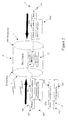
- one embodiment of the present invention relates to a wireless communication system shown generally by reference numeral 100, having a base station 10 and one or more consumer premises equipment (CPEs) 30.
- the base station 10 may be further connected to a backhaul network shown generally by reference numeral 23 through a network router or switch 20.
- CPEs consumer premises equipment
- the base station 10 communicates with each of the CPEs 30 wirelessly through a first communication standard incorporating a time division multiplexing (TDM) organizational scheme.
- the first communication standard may include a wireless communication standard based on the series of IEEE 802.16 (WiMAX) standards. More preferably, the first communication standard may be based on the IEEE 802.16 standard defined by the 802.16-2009 amendment (IEEE 802.16E).
- IEEE 802.16E 802.16-2009 amendment
- the series of IEEE 802.16 standards are hereby incorporated by reference in their entireties.
- the CPEs 30 may be end-user devices shown, for example, by CPE "C” 30.
- the CPE "C” 30 may be a mobile device, a computer, or the like, communicating with the base station 10 directly over the WiMAX communication channel.
- the CPEs 30 may be considered wireless access points shown, for example, by CPEs "A" and "B” in Figure 1 .
- the CPEs 30 may be operable to share the communication channel to the base station 10 with one or more electronic devices 50 connected to the CPE 30 via a local router or layer 2 (L2) switch (e.g. router/L2 switch 40).
- L2 switch e.g. router/L2 switch 40
- the router/L2 switch 40 may be wired or wireless, communicating with the electronic devices 50 over one of various communication standards, such as IEEE 802.3 (Ethernet), IEEE 802.11 (Wifi), 802.1Q, BluetoothTM, other 802.15 Wireless PAN standards, and the like.
- the base station 10 may be connected to a CPE 30 acting as a wireless access point, sharing the communication channel implemented in WiMAX with one or more associated mobile devices, computing devices, printers, and the like, over a Wifi or Ethernet connection.
- Connectivity to the internet, or other network resources, by the electronic devices 50 may be routed through the CPE 30, over the communication channel and to the internet via the base station 10.
- the base station 10 may be further connected to further network resources (not shown), through a network router or switch 20 to the backhaul network 23,.
- the base station 10 is connected to the router 20 by a wired port 13. While other standards are possible, the connection to the network router 20, and to the other network resources, may occur over the IEEE 802.3 (Ethernet) and IEEE 802.1Q (VLAN Tagging) standard.
- the base station 10 is operable to learn about the CPEs 30 and the electronic devices 50 via the messages 120 sent over the communication channel.
- the base station 10 identifies the individual CPE 30 or electronic device 50, by its unique Media Access Control (MAC) address 320s.
- the base station 10 stores this information in a look-up table 12. For example, as messages 120 are sent by the base station 10 from either the CPE 30 or the network router 20, the MAC address of the sender or source 320s is logged and placed into the look-up table 12 stored on the base station 10.
- MAC Media Access Control
- the base station 10 is then operable to send or forward the message 120 to its intended recipient identified by the destination MAC address 320d in the message 120.
- the message 120 received by the base station 10 may be sent as a unicast message 120, a multicast message 122 or a broadcast message to one or more of the plurality of CPEs 30 and electronic devices 50 of wireless communication system 100, accessible to the base station 10.
- a unicast message 121 is destined for a specific CPE 30 or electronic device 50.
- the originator of the unicast message 121 may include a unique identifier such as a destination MAC address 320d to specify the recipient of the unicast message.
- a multicast message 122 is destined for a subset of the CPEs 30 and electronic devices 50 accessible to the base station 10.
- the base station 10 may include or act upon a group identifier 330 or VLAN included with the multicast message 122 and/or stored on the base station 10 to forward the multicast message 122, to the proper recipients.
- the multicast message 122 may have a plurality of destination MAC addresses 320d, or, a group identifier 330 which identifies a group of devices 50 in the look-up table 12.
- a broadcast message also known as broadcast flooding, forwards the message to all the CPEs 30 and electronic devices 50 accessible to the base station 10.
- the base station 10 may forward uplink broadcast message based on information stored on the base station 10, such as on the look-up table 12.
- look-up table 12 is depicted in one preferred embodiment. It should be understood that other look-up tables are possible and the description and construction of the look-up table 12 herein should not be construed as limiting.
- the look-up table 12 is stored within the base station 10. It may be referred to by the base station 10 in order to determine how to forward a received message 120. In some embodiments, the base station 10 may act on a received message 120 according to information from either the originator of the message (i.e., either a CPE 30 or an electronic device 50), or its recipient, based on information stored within the look-up table 12.
- Information stored within the look-up table 12 may include different fields necessary to allow the base station 10 to forward a message 120 effectively without requiring further information from the network router 20.
- the look-up table 12 may include an index 310 to keep track of the different devices 30, 50 utilizing the base station 10 to forward messages 120.
- the different devices 30,50 may then be associated with their corresponding MAC addresses 320 and a group identifier 330 which, in one preferred embodiment, may potentially be a Virtual Local Area Network (VLAN).
- VLAN Virtual Local Area Network
- the look-up table 12 may also associate the electronic device 50 with both its device MAC address 320 and the associated CPE MAC address 350.
- Each device 30, 50 may be stored as a separate device entry 302 in the look-up table 12.
- the device entry 302A associated with the index 1 has a device MAC address 320 of 00:1D:60:FE:F3:36.
- the device entry 302A is associated with a group identifier 330 (or VLAN) identified as "200" and a CPE MAC address 350 of 00:13:D5::01:5A.
- Other device entries 302B, 302C store information specific to a specific device. If a device does not have a value for a field stored within the look-up table 12 (e.g. an associated CPE MAC address 350 for device entry 302C because that entry 302C may be for a router on the network side 20), the CPE field 350 may be left blank or otherwise identified as not having a stored value.
- a device does not have a value for a field stored within the look-up table 12 (e.g. an associated CPE MAC address 350 for device entry 302C because that entry 302C may be for a router on the network side 20)
- the CPE field 350 may be left blank or otherwise identified as not having a stored value.
- the interface field 360 may store the relationship between the base station 10 and device entry 302.
- the base station 10 may store that the relationship between the base station 10 and a specific device entry 302B is over the wireless communication standard (indicated in the interface field 360 as "RF").
- RF wireless communication standard
- Other network interface indicators are possible, such as for example, "network” meaning over network 23 and "local” meaning packets that originate from the base station 10 itself, such as management packets.
- the look-up table 12 may also be stored by the look-up table 12, such as aging time field 340 and the like.
- the aging time field 340 may update how long the base station 10 has gone since a message 120 was received from a particular device stored in its look-up table 12.
- the base-station 10 may purge device entries 302 from the look-up table 12 if a new message 120 is not received from a particular device 30, 50 within a specified aging time 340.
- any number of fields may be stored in the look-up table 12 to improve the efficiency and forwarding capabilities of the base station 10.
- the base station 10 is operable in the Ethernet Convergence Sublayer (Ethernet-CS) mode according to one embodiment of the present invention.
- Ethernet Convergence Sublayer Ethernet-CS
- non-IP protocols are supported.
- messages received at the base station 10 for communication to an electronic device 50 associated with a particular CPE 30, and messages received at a CPE 30 for transmission over the network via the base station 10 are encapsulated by the first communication standard (i.e. the WiMAX group of standards such as, preferably, IEEE 802.16E) for transmission over the wireless communication channel, shown generally by reference numeral 402.
- the first communication standard i.e. the WiMAX group of standards such as, preferably, IEEE 802.16E
- Ethernet-CS mode neither the base station 10 nor the CPEs 30 reply to Address Resolution Protocol (ARP) requests, but instead pass all traffic through to its intended recipient.
- ARP Address Resolution Protocol
- the base station 10, and the CPE 30 if acting as an access point, is operable to learn the source MAC addresses of all incoming packets from the Ethernet header 420.
- the base station 10 may then store the source MAC address information in its look-up table 12 as discussed above.
- the base station 10 may be operable to behave as an L2 switch shown schematically in configuration 500. While the base station 10 sends and receives messages from the CPEs 30 over a single RF Interface (e.g., according to time division duplexing or frequency division duplexing), the base station 10 can associate each CPE 30 with a logical port 510 identified, for example, as Lport1, Lport2, Lport3, Lport4, Lport 5. Logical ports 501 may be used to provide radio connectivity to the CPEs 30. Each logical port Lport1, Lport2, Lport3, Lport4, Lport5 may have a number of logical connections 520 identified, for example, as Lcon1, Lcon2 per CPE 30 that are used to forward traffic over the air.
- Each logical connection Lcon1, Lcon2 may have a different Quality of Service (QoS), so as to enable the base station 10 to maintain priority between different applications using the shared air medium in this case, the radio frequency (RF) interface identified generally by reference numeral 402.
- QoS Quality of Service
- different QoS may be required for specific types of applications undertaken by the wireless communication system 100, such as for real-time multimedia applications and other applications requiring fixed bit-rate or which are delay sensitive.
- the base station 10 When the base station 10 receives a message from either the RF Interface or Network Interface, the base station 10 identifies the source MAC address 320s of the incoming packet. If the MAC address is unknown to the base station 10, the base station 10 is operable to create a new entry for the device associated with the source MAC address in the look-up table 12, before forwarding the message to its intended target. Accordingly, the base station 10 populates the look-up table 12 with MAC addresses identifying CPEs receiving and sending messages in the first communication standard. If the source MAC address is already included within the look-up table 12, the base station 10 may forward the message without creating a new entry. However, in some embodiments, the base station may first verify and/or update one or more fields associated with the known MAC address, such as for example, updating the aging time field 340.
- an IP packet may be sent by an electronic device 50 to the CPE 30 for transmission to the base station 10.
- the CPE 30 encapsulates the whole Ethernet frame and sends it to the base station 10 using the IEEE 802.16E wireless interface shown by reference numeral 401.
- the base station 10 strips off the 802.16E header and then forwards the frame to the network or to another CPE (not shown) according to the destination MAC address provided in the Ethernet header 420 and IP header 430 of the encapsulated massage 401.
- each incoming packet has to be checked against the look-up table 12 before being forwarded. If the destination MAC address is in the look-up table 12, the base station 10 will forward the packet according to the destination MAC address. If the destination MAC address is not in the look-up table 12 or the packet is a broadcast packet, the base station 10 will perform broadcast flooding of the packet to all the CPEs 30 and/or network 23 through the network router 20. This behaviour is similar to the behaviour of an L2 switch. It can be implemented efficiently in the TMD scheme of the first communication standard, in order to save the short over-the-air (OTA) resources.
- OTA over-the-air
- the base station 10 has two main functions with regards to scheduling. These include deciding which logical port LPORT 510 is served before the other and how much traffic will be sent out. Traffic prioritization in the base station 10 can be done using a number of mechanisms. In a preferred embodiment, the base station 10 uses two potential mechanisms. The first mechanism involves a strict priority. In this mechanism, the highest priority traffic is served before any low priority traffic. Priorities are given based on the logical port 510 and the logical connection 520 for each of the CPEs 30. In the second mechanism, weighted-fare priority may be used. In this mechanism, the band width across the radio frequency interface 402 is shared relatively according to the weight given to different logical ports 510.
- each logical connection 520 of each logical port 510 is determined by the committed information rate (CIR) and the maximum information rate (MIR) that are defined by the logical connection 520.
- CIR committed information rate
- MIR maximum information rate
- each multicast connection has a configurable traffic priority.
- traffic can be prioritized over other VLAN traffic. It may also be prioritized over unicast downlink traffic.
- FIG. 5B shows a further preferred embodiment of the present invention.
- a configuration 505 of the system 100 has a base station 10 sending and receiving data to the CPEs 30.
- the CPE1 sends a broadcast packet 550 through the first logical port Lport1 to the base station 10.
- the broadcast packet 550 is then replicated and broadcast back as packet 551.
- the pack is not replicated N-1 times for each of the CPEs in order to exclude the originating one. Rather, the replicated return broadcast packet 551 is sent once over the broadcast connection to all of the CPEs 30.
- the wireless communication system 100 is depicted according to at least three topologies 600A, 600B and 600C.
- the network topologies 600A, 600B and 600C in the present embodiments should not be construed as limiting.
- the system 100 has a topology 601 with the base station 10 connected to one or more CPEs 30, the individual CPEs 30 depicted as 30A, 30B, 30C and 30D.
- Each CPE 30A, 30B, 30C, 30D has at least one electronic device 50 associated therewith.
- the MAC addresses of each of the electronic devices 50 is stored in the base station 10 within the look-up table 12 as discussed above.
- the base station 10 may also store group identifier information, such as Virtual Local Area Network (VLAN) information.
- the group identifier 330 may be stored within the look-up table 12 containing MAC address information, also stored in the base station 10.
- the base station 10 When a message shown generally by reference numeral 650m is sent from any electronic device 50A, the base station 10 is operable to forward the message 650m to its intended target, without accessing the network router 20, if the base station 10 recognizes the intended recipient(s) and has the information stored in the look-up table 12. If the base station 10 recognizes the intended recipient to be on the network side , the base station 10 may forward the message 650m to the network router 20 to perform routing. If the recipient of the message is not recognized, the base stations 10 may flood the packet towards the router 20 and the rest of the CPEs based on the mechanism described in Figure 5B .
- Figure 6A , Figure 6B , and Figure 6C depict various forms of routing according to at least some aspects of the present invention. It should be understood that other embodiments are possible, with the present embodiments not construed as limiting.
- Figure 6A illustrates the network topology 600A of a wireless communication system 100 in at least one embodiment.
- the electronic device 50A associated with the CPE 30A is operable to send a unicast message to the electronic device 50B associated with the CPE 30B.
- the electronic device 50A first sends an IP-based message to the router/L2 switch 40A over a second communication standard, such as for example, an Ethernet connection.
- the router/L2 switch 40A then forwards the message to the CPE 30A.
- the originating CPE 30A then encapsulates all of the Ethernet frame of the message and uplinks a unicast message to the base station 10 including the MAC address of the target electronic device 50B.
- the base station 10 then strips the wireless header, in a preferred embodiment a 802.16E header, and forwards the message. If the base station 10 recognizes from its look-up table 12 that the intended target (electronic device 50B) is associated with CPE 30B, the base station 10 forwards the message to CPE 30B by sending a downlink unicast message, without accessing the network router 20.
- the base station 10 refers to the look-up table 12 to locate switching information and re-encapsulates the message. Referring briefly to the look-up table 12 in Figure 3 , the base station 10 is operable to locate the device entry 302B for the electronic device 50B and then to locate the associated CPE MAC address 350 for forwarding the message. Once received, the recipient CPE 30B strips the wireless header and forwards the message to the intended electronic device 50B via the router/L2 switch 40B in the second communication standard, in this embodiment Ethernet..
- a method 700 for wirelessly communicating multicast messages between a plurality of CPEs 30 is illustrated according to at least one embodiment of the present invention.
- the method uses the wireless communication system 100 to send an uplink multicast message to the base station 10 destined to a subset of the CPEs 30 in the wireless communication system 100, based on a group identifier.
- Each CPE 30 has a unique MAC address and the CPEs 30 and base station 10 are operable to communicate using a first communication standard that incorporates time division multiplexing over a wireless port.
- the base station 10 and the CPEs 30 are operable to send and receive wireless signals to each other utilizing a wireless interface 402 based on a TDM scheme, as defined by the first communication standard such as the WiMAX group of standards.
- an originating CPE 30 is operable to send an uplink multicast message to the base station 10 to be sent to other CPEs 30.
- the uplink multicast message shown generally by reference numeral 650m is sent to members of a virtual local area network (VLAN) or other CPE grouping as a multicast message.
- the multicast message 650m may be sent by the originating electronic device 50a, which is operable to send an uplink multicast message to the base station 10 to be sent to other electronic devices 50 (or CPEs 30) via the base station 10.
- the uplink multicast message 650m may include a group identifier identifying a group of CPEs to receive the uplink multicast message.
- the electronic devices 50a and 50b associated with two CPEs 30A, 30B share the group identifer VLAN 10 and the electronic devices 50C, 50D associated with two different CPEs 30C, 30D share the group identifier VLAN 20.
- the base station 10 is operable to receive the uplink multicast message.
- the message is received over the first communication channel utilizing a TDM scheme.
- the base station 10 in BLOCK 730, is operable to convert the uplink multicast message 650m to a downlink multicast message using the look-up table 12 stored at the base station 10.
- the base station 10 is operable to store a group identifier 330, such as a VLAN, for uniquely identifying a group of CPEs 30 and/or a group of devices 50.
- the base station 10 may use this group identifier 330 for determining where to forward the uplink multicast message. If a message from a given electronic device 50a, and its associated CPE 30a, is multicast to its associated VLAN (i.e. VLAN 10), the base station 10 is able to associate the group identifier 330 with specific CPEs 30 and electronic devices 50 associated with the group identifier 330 based on information contained within the look-up table 12.
- the base station 10 transmits the downlink multicast message to the CPEs 30, where each CPE 30 has its MAC address stored in the look-up table 12.
- the base station 10 will create a multicast service flow which will send the message to the identified CPEs 30 and/or electronic devices 50 identified in the multicast message 650m. If the multicast message identifies all of the electronic devices 50 in a VLAN, such as VLAN 10, the multicast service flow is created inherently as a part of the VLAN in the base station 10.
- the downlink multicast message is sent to all of the CPEs 30 in wireless communication system 100, including the originating CPE. In other embodiments, the downlink message is sent to a single CPE 30 or a subset of all the CPEs 30 associated or registered with the base station 10. It is understood that while the examples are given with respect to the multicast messages 650m originating from a device 50a, the invention would work equally if the multicast message 650m originated from a CPE 30 as shown in Figure 5B .
- the look-up table 12 stored on the base station contains the MAC addresses of each of the CPEs 30 associated or registered with the base station 10.
- the downlink message may be sent in a single information burst according to the time division multiplexing scheme.
- the downlink message may be sent in a single TDM timeslot that is assigned to the intended group of CPEs 30, such as a multicast service flow as described herein.
- the group of CPEs 30 may be assigned to the timeslot provided by the scheduling algorithm associated with the first communication standard (i.e. the WiMAX group of standards).
- the first communication standard i.e. the WiMAX group of standards
- the base station 10 may not automatically forward the message to its intended recipient, even if it already has switching information stored within the look-up table 12. Instead, the base station 10 may forward the message to the router 20. This feature may enhance efficiency and security, as the base station 10 is capable of efficiently forwarding messages within the same broadcast domain, while simultaneously separating disparate parts (VLANS) of the network. In this manner, the base station 10 is behaving as a L2 switch, and segregates the different VLANs into different broadcast domains.
- VLANS disparate parts
- each logical port LPORT 510 shown in Figures 5A and 5B and communicating a specific CPE 30, may be part of a specific VLAN.
- the base station may communicate on both LPORT1 and LPORT3, based on the group identifier 330 and associated CPE MAC addresses 350 stored in look-up table 12 to decrease bandwidth and processing time.
- the electronic devices 50 associated with one or more CPEs 30, may be organized by group identifier shown generally by reference numeral 330 in Figure 3 , irrespective of how they are connected to the network.
- electronic devices 50A, 50B, 50C, 50D may be part of different group identifiers 330, shown in Figure 6B as being part of different VLANs 10 and 20, even if they are connected to the base station 10 via the same CPEs 30A, 30B.
- the electronic devices 50 for a specific group identifier 330 may be segregated according to the associated CPE 30, this is not required.
- every electronic device 50, associated with every CPE 30 in range or connected to a base station 10 may be associated with the same group identifier 330.
- a CPE 30 may have one, many or no group identifiers 330 associated with the electronic devices 50, associated with the CPE 30.
- Each CPE 30 associated with a wireless communication system 100 may have different group identifiers for groups of electronic devices 50 associated with that particular CPE 30. Different combinations of group identifiers shared between CPEs 30 and electronic devices 50 are possible.
- FIG. 6B another network topology 600B is shown having an electronic device 50A, associated with VLAN 10, and an electronic device 50B, associated with VLAN 20, are both associated with the same CPE 30A.
- Other electronic devices 50 (not shown), associated with other CPEs 30 (not shown), may also be associated with either VLAN 10 or VLAN 20.
- An electronic device 50 is operable to send a multicast message to a group of electronic devices 50 (or CPEs 30), even if the electronic device 50 is not associated with the same CPE 30, by uniquely identifying the group of electronic devices 50 (or CPEs 30) by using the associated group identifier 330. Any one of the CPEs 30 in the group is operable to specify the group of CPEs 30 or electronic devices 50 to receive the multicast message 650 by placing the corresponding group identifier 330 in the uplink multicast message.
- the uplink multicast message 650 is sent by an electronic device 50A associated with a CPE 30A
- the uplink multicast message 650 is sent by the CPE 30A to the base station 10 over the first communication channel.
- the originating electronic device 50A or CPE 30A can specify the group of CPEs 30 to receive the multicast message by placing the corresponding group identifier 330 in the uplink multicast message.
- the base station 10 may transmit the downlink multicast message to the group of CPEs 30, identified by the group identifier 330.
- the base station may send the downlink multicast message in a single information burst, including to the CPE 30A or electronic device 50A that originally sent the uplink multicast message.
- the single information burst may occur over a single TDM timeslot. In other embodiments, the single information burst may occur over a number of sequential timeslots.
- the downlink multicast message 650 is sent to the CPEs simultaneously and is received by the appropriate recipient CPEs at the same time, based on the group identifier.
- the originating CPE 30a or electronic device 50a that sent the uplink multicast message may drop the received downlink multicast message.
- the originating CPE 30 is operable to send a multicast message 650 to the entire group identified by the group identifier 33 in the message 650 and the base station 10 can send the downlink multicast message in a single information burst or TDM timeslot without having to make any modifications to the downlink message.
- the message may be sent to the entire group of CPEs, with the originating CPE operable to recognize that a message that it has received from the base station 10 corresponds to the uplink multicast message 650 that it sent and take appropriate action.
- the originating CPE may drop the downlink multicast message as illustrated in Figure 5B and discussed above and also shown in BLOCK 760 of Figure 7 .
- the base station 10 will create a multicast service flow to send the downlink message to all the devices 50 and CPEs 30 in VLAN 10 in Figure 6A , including the originating device 50a, because this saves processing time and bandwidth.
- the originating device 50a will then recognize that the received downlink message corresponds to the sent uplink multicast message 650m and disregard or drop the downlink message as discussed above with respect to Figure 5B and shown in BLOCKS 750 and 760 in Figure 7 . It is understood that while examples are given with respect to multicast messages 650m originating from a device 50a, the invention would work equally well if the multicast message 650m originated from a CPE 30 as referred to in Figure 7 .
- a CPE 30 may recognize that the downlink multicast message it has received from the base station 10 does not need to be forwarded to any electronic devices 50 associated with the CPE 30, as the only electronic device 50 associated with the group identifier is the originating electronic device, which sent the uplink multicast message in the first instance. For example, in Figure 6B , if the CPE 30a recognizes that there are no additional electronic devices 50 other than the originating electronic device 50b associated with the specified group identifier VLAN 10, the CPE 30a may be operable to drop the downlink multicast message, completely.
- the CPE 30a may drop the downlink multicast message for the originating electronic device 50b, only, and forward the downlink multicast message to the non-originating electronic devices (not shown). In alternate embodiments, the CPE 30a may continue to forward the downlink multicast message to all the electronic devices 50b associated with the CPE 30a and group identifier VLAN 10, and allow the originating electronic device 50b to drop the downlink multicast message, itself.
- FIG. 6C yet another network topology 600C is depicted illustrating two base stations 10 having a plurality of electronic devices 50 associated with one or more CPEs 30.
- the base stations 10 are connected to each other through a network switch 22, such as for example, an Ethernet switch complying with the IEEE 802.3 (Ethernet) series of standards.
- a network switch 22 such as for example, an Ethernet switch complying with the IEEE 802.3 (Ethernet) series of standards.
- the network switch 22 is operable to learn the MAC addresses of devices connected to the network switch's 22 physical Ethernet ports (not shown).
- the wireless communication system 100 is operable to define the relevant VLANs and associate the relevant CPEs 30 with each VLAN. No extra configuration or provisioning is required, as the multicast service flow is created inherently as part of VLAN creation in the base station 10.
- tagged traffic is recognized as multicast traffic according to the required message frame structure incorporating the group identifier, the tagged traffic is replicated and sent to all the CPEs 30 that are subscribed to the VLAN. Accordingly, once associated with a specific VLAN, tagged traffic specific to that VLAN will be associated with the relevant multicast service flow.
- the L2 message may be forwarded to all the CPEs 30 within the wireless communication system 10 over a broadcast connection.
- the wireless communication system 100 For the wireless communication system 100 to act in multicast mode, ensuring that a multicast message reaches every possible electronic device 50 or CPE 30 associated with a group identifier, every CPE 30 in the wireless communication system 100 with members associated with the group identifier must be in the look-up table 12 stored in the base station 10.
- the group identifier will not be recognized by the base station 10 at all (i.e., no base station 10 with either an electronic device 50 or CPE 30 is indexed in the look-up table 12).
- the base station 10 when receiving an uplink multicast message, the base station 10 will correctly forward the multicast message to all the base stations 10 having members associated with the group identifier or will not recognize the group identifier at all, and will resort to broadcasting the uplink multicast message to all network devices 30, 50. Any sites not indexed with the base station 10 receiving the uplink multicast message will not receive the multicast message.
- the MAC address for various electronic devices including the consumer premises equipment. It is understood that the MAC address is being used as a unique identifier for the corresponding electronic device. However, the invention is not limited to use of the MAC addresses for this purpose. Rather, any unique identifier can be used as an address to uniquely identify the CPEs and other electronic devices and it is understood that the invention is not limited to use of MAC addresses for this purpose.
Landscapes
- Engineering & Computer Science (AREA)
- Computer Networks & Wireless Communication (AREA)
- Signal Processing (AREA)
- Multimedia (AREA)
- Mobile Radio Communication Systems (AREA)
- Small-Scale Networks (AREA)
Abstract
Description
- This invention relates to wireless networks. More specifically, this invention relates to a wireless network implementing the Worldwide Interoperability for Microwave Access (WiMAX) standard.
- A wireless network is a common type of computer network that incorporates two or more devices capable of communicating wirelessly. The prevalence of wireless devices has grown exponentially with the adoption of mobile phones and other types of personal and consumer electronics, i.e. smart phones, tablets, netbooks, laptop computers and other wireless electronic devices.
- The growth of wireless networking has grown in parallel with the adoption of Wi-Fi™, the series of wireless local area network (wireless LAN/WLAN) protocols based on the series of Institute of Electrical and Electronics Engineers (IEEE) 802.11 standards. The adoption of Wi-Fi™ has allowed LANs to be deployed economically without the need to run cables, reducing costs and increasing flexibility. Furthermore, high adoption has increased the appetite for wireless data and created a market for faster networks with increased speed and capacity.
- Worldwide Interoperability for Microwave Access (WiMAX) is a next generation wireless protocol introduced by the WiMAX Forum. WiMAX refers to a specific type of the series of interoperable IEEE 802.16 standards which are incorporated herein by reference. WiMAX offers increased speeds and improved range over WLANs utilizing Wi-Fi™, and supports fixed, nomadic and mobile deployments. Furthermore, companies have employed the standard to provide mobile broadband across large geographical areas and to compete with third generation mobile technologies, such as Global System for Mobile Communications (GSM) and Code Division Multiple Access (CDMA). WiMAX is often considered as an economical alternative to last mile Internet access currently served by cable or digital subscriber lines (DSL). The flexible bandwidth allocation and multiple built-in types of Quality-of-Service (QoS) support in the WiMAX network allow for deployments that include high-speed Internet access, Voice Over Internet Protocol (VoIP) and video calls, multimedia chats and mobile entertainment.
- The IEEE 802.16 series of standards provide the air interface for a number of wireless communication standards, but does not necessarily define a standard WiMAX network. However, the WiMAX Forum's Network Working Group (NWG) has identified a standard set of end-to-end requirements, architecture and protocols for WiMAX, using IEEE 802.16e-2005 as the air interface. According to a WiMAX standard, the overall network may be logically divided into three parts: Consumer Premises Equipment (CPE), the Access Service Network (ASN) and the Network Operations Centre (NOC).
- Consumer Premises Equipment (CPE) are devices used by the end user to access the WiMAX network. In fixed deployments, the CPE may be a WiMAX access point used to provide users with access to the WiMAX network through standard fixed or wireless LANs (e.g. using Wi-Fi™). In other embodiments, the CPE may be a mobile phone, a computing device or the like, able to access the WiMAX network directly when in range of a base station.
- A Network Operations Centre (NOC) provides connectivity to the Internet, Application Service Providers (ASP), other public networks, and corporate networks. According to conventional WiMAX networks, the NOC also includes Authentication, Authorization and Accounting (AAA) servers that support authentication for the devices, users, and specific services. The NOC also provides user policy management of QoS and security and NOC is also responsible for IP address management, support for roaming between different NSPs, location management between ASNs, and mobility and roaming between ASNs. As WiMAX was developed at least in part to support the next generation of mobile devices, the NOC is also capable, in some implementations, of communicating with the Public Switched Telephone Network (PSTN) and 3rd Generation Partnership Projects (3GPP/3GPP2) via a Gateway and integrating Operations Support Systems (OSS) and Business Support Systems (BSS) within the NOC environment.
- In prior art WiMAX architectures, communication between an ASN and both the CPEs and NOC is segregated. On the subscriber side, the ASN is operable to communicate with the CPEs using a base station. On the network side, communication between the NOC and the ASN occurs through an ASN Gateway (ASNGW). Data received at the ASN from a CPE via a base station will be passed to the ASNGW for proper message forwarding. The ASNGW of the prior art devices may communicate with the NOC to retrieve message forwarding instructions. As an ASN may cover a large geographic area, multiple base stations may be grouped within a single ASN, with one or more ASNGWs managing and tracking the flow of data amongst several base stations which may create unpredictable latency.
- The WiMAX standard supports both Frequency Division Duplexing (FDD) and Time Division Duplexing (TDD), although the widely deployed WiMAX
Release 1 based on IEEE 802.16e technology only supports TDD as the duplexing mode. In any event, TDD is better positioned for mobile Internet devices where data transmission is asymmetrical. - TDD provides full duplex communication over a communication link applying time-division multiplexing (TDM). This form of implementation is simpler and cheaper than one utilizing FDD, as transceiver designs for TDD implementations are less complex and therefore less expensive. The uplink and downlink data rates between BS and CPE are managed by the scheduling algorithm, which allocates recurrent timeslots. Outbound transmissions from the BS are broadcast in addressed frames. Each CPE can then pick off those frames addressed to it. Accordingly, the dynamic allocation of traffic over a single communication link can be optimized based on load usage. In other words, capacity can be added or taken away from specific CPEs as the traffic loads fluctuate.
- In conventional WiMAX networks, the base station (BS) will control access to the channel. Users wishing to transmit inbound to the BS must first send a request on a contention-based access channel. Exclusive permission to use the inbound traffic channel is then allocated by the BS using a system of transmission grants. Each CPE is allocated a transmission slot in time-frequency domain, thus there are no collisions.
- Multicast is a form of one-to-many distribution. With similarities to broadcasting, multicasting allows a source to transmit a message to many receivers simultaneously. However, a difference between broadcasting and multicasting is that multicasting may limit the pool of receivers to those that are identified as part of the receiver group.
- Multicasting is used in situations where a message needs to be sent to many receivers from a single transmission source. Instead of individually packaging a message for each individual receiver, the transmission source utilizing multicasting may send the message once. Common applications for multicast include the deployment of streaming media, such as Internet radio and television programs.
- However, the prior WiMAX networks suffer from the disadvantage that any CPE-to-CPE multicast transmissions must be managed by and routed from the Access Network even for the CPEs that are behind the same Base Station.
- Accordingly, it is an object of this invention to at least partially overcome some of the disadvantages of the prior art. Accordingly, it is an object of this invention to provide an improved type of WiMAX based system and method which stands alone, decreases message transmission latency and facilitates multicast transmissions initiated by an originating CPE and to be broadcast to all of the CPEs or a predefined group of the CPEs.
- Accordingly, in one of its aspects, this invention resides in a wireless communication system comprising: a plurality of consumer premises equipments (CPEs) for sending and receiving wireless signals in a first communication standard using time division multiplexing (TDM), each CPE having a unique MAC address; a base station having a wireless port for sending and receiving wireless signals to each of the plurality of CPEs in the first communication standard and using TDM, said base station having stored therein a look-up table containing the MAC addresses of each of the plurality of CPEs; wherein any one of the plurality of CPEs can uplink a multicast message to the base station to be sent to the CPEs; and wherein in response to receiving the uplink multicast message, the base station sends a downlink multicast message to the CPEs having their MAC addresses stored in the look-up table and identified in the uplink multicast message.
- A further aspect of the invention resides in a method of wirelessly communicating multicast messages between a plurality of consumer premises equipment (CPEs) in a first communication standard using Time Division Multiplexing (TDM), each of said CPEs having a unique MAC address, said method comprising: sending, from an originating CPE of the plurality of CPEs, an uplink multicast message to a base station, said base station having a wireless port for sending and receiving wireless signals to each of the plurality of CPEs in the first communication standard and using TDM, said base station also having stored therein a look-up table containing the MAC addresses of each of the plurality of CPEs; receiving, at the base station, the uplink multicast message; converting, at the base station, the uplink multicast message to a downlink multicast transmit message using the look-up table stored at the base station; and transmitting, by the base station, the downlink multicast message to the CPEs having their MAC addresses stored in the look-up table and identified in the uplink multicast message.
- Accordingly, one advantage of at least one aspect of the present invention is a base station capable of reducing end-to-end latency. By storing information pertaining to a Consumer Premises Equipment (CPE) at the base station, the base station is capable of redirecting wireless traffic received from one CPE to second CPE without having to resort to forwarding the message to a Network Operations Center (NOC) and/or Access Network or otherwise receive additional routing information. In this way, messages received from the first CPE can be retransmitted to the second CPE immediately without the use of a router, reducing end-to-end latency and network resources.
- In a further aspect of the present invention, the present invention provides that a CPE can uplink a multicast message over a WiMAX network. In this way, individual CPE's can access the one-to-many communication channel allowing multicast messages to other CPE's by indicating a message as a multicast message when uploading to the WiMAX base station. Messages labeled as multicast messages will then be forwarded by the base station to the appropriate multicast group using information stored at the base station.
- In a further aspect, the base station will transmit the multicast message to all of the CPEs in the designated group, including the CPE that initiated the multicast message. When the originating CPE recognizes the multicast message as one that it originated, the originating CPE will drop the multicast message. This improves overall efficiency of the wireless system and decreases bandwidth and processing time.
- A further advantage of the present invention is the ability to form Virtual Local Area Networks amongst end users of a WiMAX network in a simple and cost effective manner. By accessing the information stored within a base station, the base station is capable of rerouting messages to VLAN members without having to resort to IP-tunneling or other more convoluted techniques. In this way, access and security of VLANs can be managed simply and effectively by a base station. CPEs can be grouped logically into a single broadcast domain. Further, broadcast traffic can be confined to specific VLAN members only, resulting in increased security and a reduction of traffic to the rest of the network.
- Further aspects of the invention will become apparent upon reading the following detailed description and drawings, which illustrate the invention and preferred embodiments of the invention.
- In the drawings, which illustrate embodiments of the invention:
-
Figure 1 is a network diagram of a wireless communication system in accordance with an embodiment of the present invention; -
Figure 2 is a schematic illustration of the message routing behaviour of a base station in accordance with an embodiment of the present invention; -
Figure 3 is a look-up table for a base station in accordance with an embodiment of the present invention; -
Figure 4 is a network packet diagram illustrating the encapsulation of a network frame in accordance with an embodiment of the present invention; -
Figure 5A is a routing diagram of a base station in accordance with an embodiment of the present invention; -
Figure 5B is a routing diagram of a base station in accordance with a further embodiment of the present invention; -
Figure 6A is an illustration of a network topology for a wireless communication system in accordance with an embodiment of the present invention; -
Figure 6B is an illustration of a network topology for a wireless communication system in accordance with another embodiment of the present invention; -
Figure 6C is an illustration of a network topology for a wireless communication system in accordance with another embodiment of the present invention; and -
Figure 7 is a method for wireless communicating multicast messages between a plurality of CPEs in accordance with an embodiment of the present invention. - Preferred embodiments of the invention and its advantages can be understood by referring to the present drawings. In the present drawings, like numerals are used for like and corresponding parts of the accompanying drawings.
- Preferred embodiments of the invention and its advantages can be understood by referring to the present drawings. In the present drawings, like numerals are used for like and corresponding parts of the accompanying drawings.
- As shown in
Figure 1 , one embodiment of the present invention relates to a wireless communication system shown generally byreference numeral 100, having abase station 10 and one or more consumer premises equipment (CPEs) 30. Thebase station 10 may be further connected to a backhaul network shown generally byreference numeral 23 through a network router orswitch 20. - The
base station 10 communicates with each of theCPEs 30 wirelessly through a first communication standard incorporating a time division multiplexing (TDM) organizational scheme. For example, the first communication standard may include a wireless communication standard based on the series of IEEE 802.16 (WiMAX) standards. More preferably, the first communication standard may be based on the IEEE 802.16 standard defined by the 802.16-2009 amendment (IEEE 802.16E). The series of IEEE 802.16 standards are hereby incorporated by reference in their entireties. - In at least one embodiment, the
CPEs 30 may be end-user devices shown, for example, by CPE "C" 30. For example, the CPE "C" 30 may be a mobile device, a computer, or the like, communicating with thebase station 10 directly over the WiMAX communication channel. - In alternate embodiments, the
CPEs 30 may be considered wireless access points shown, for example, by CPEs "A" and "B" inFigure 1 . TheCPEs 30 may be operable to share the communication channel to thebase station 10 with one or moreelectronic devices 50 connected to theCPE 30 via a local router or layer 2 (L2) switch (e.g. router/L2 switch 40). Furthermore, the router/L2 switch 40 may be wired or wireless, communicating with theelectronic devices 50 over one of various communication standards, such as IEEE 802.3 (Ethernet), IEEE 802.11 (Wifi), 802.1Q, Bluetooth™, other 802.15 Wireless PAN standards, and the like. In a preferred embodiment, thebase station 10 may be connected to aCPE 30 acting as a wireless access point, sharing the communication channel implemented in WiMAX with one or more associated mobile devices, computing devices, printers, and the like, over a Wifi or Ethernet connection. Connectivity to the internet, or other network resources, by theelectronic devices 50 may be routed through theCPE 30, over the communication channel and to the internet via thebase station 10. - The
base station 10 may be further connected to further network resources (not shown), through a network router or switch 20 to thebackhaul network 23,. In some embodiments, thebase station 10 is connected to therouter 20 by a wiredport 13. While other standards are possible, the connection to thenetwork router 20, and to the other network resources, may occur over the IEEE 802.3 (Ethernet) and IEEE 802.1Q (VLAN Tagging) standard. - Referring now to
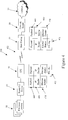
Figure 2 , thebase station 10 is operable to learn about theCPEs 30 and theelectronic devices 50 via themessages 120 sent over the communication channel. Asmessages 120 are sent tobase station 10 by theCPE 30, or by theelectronic devices 50 via theCPE 30, thebase station 10 identifies theindividual CPE 30 orelectronic device 50, by its unique Media Access Control (MAC)address 320s. Thebase station 10 stores this information in a look-up table 12. For example, asmessages 120 are sent by thebase station 10 from either theCPE 30 or thenetwork router 20, the MAC address of the sender orsource 320s is logged and placed into the look-up table 12 stored on thebase station 10. - The
base station 10 is then operable to send or forward themessage 120 to its intended recipient identified by thedestination MAC address 320d in themessage 120. Themessage 120 received by thebase station 10 may be sent as aunicast message 120, amulticast message 122 or a broadcast message to one or more of the plurality ofCPEs 30 andelectronic devices 50 ofwireless communication system 100, accessible to thebase station 10. - A
unicast message 121 is destined for aspecific CPE 30 orelectronic device 50. The originator of theunicast message 121 may include a unique identifier such as adestination MAC address 320d to specify the recipient of the unicast message. - A
multicast message 122 is destined for a subset of theCPEs 30 andelectronic devices 50 accessible to thebase station 10. Thebase station 10 may include or act upon agroup identifier 330 or VLAN included with themulticast message 122 and/or stored on thebase station 10 to forward themulticast message 122, to the proper recipients. In this case, instead of a singledestination MAC address 320d, themulticast message 122 may have a plurality of destination MAC addresses 320d, or, agroup identifier 330 which identifies a group ofdevices 50 in the look-up table 12. - A broadcast message, also known as broadcast flooding, forwards the message to all the
CPEs 30 andelectronic devices 50 accessible to thebase station 10. Thebase station 10 may forward uplink broadcast message based on information stored on thebase station 10, such as on the look-up table 12. - Referring now to
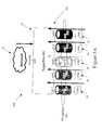
Figure 3 , a look-up table 12 is depicted in one preferred embodiment. It should be understood that other look-up tables are possible and the description and construction of the look-up table 12 herein should not be construed as limiting. - In a preferred embodiment, the look-up table 12 is stored within the
base station 10. It may be referred to by thebase station 10 in order to determine how to forward a receivedmessage 120. In some embodiments, thebase station 10 may act on a receivedmessage 120 according to information from either the originator of the message (i.e., either aCPE 30 or an electronic device 50), or its recipient, based on information stored within the look-up table 12. - Information stored within the look-up table 12 may include different fields necessary to allow the
base station 10 to forward amessage 120 effectively without requiring further information from thenetwork router 20. For example, the look-up table 12 may include anindex 310 to keep track of thedifferent devices base station 10 to forwardmessages 120. Thedifferent devices group identifier 330 which, in one preferred embodiment, may potentially be a Virtual Local Area Network (VLAN). Further, if the device is anelectronic device 50 associated with aCPE 30, the look-up table 12 may also associate theelectronic device 50 with both itsdevice MAC address 320 and the associatedCPE MAC address 350. - Each
device separate device entry 302 in the look-up table 12. For example, thedevice entry 302A associated with theindex 1 has adevice MAC address 320 of 00:1D:60:FE:F3:36. Further, thedevice entry 302A is associated with a group identifier 330 (or VLAN) identified as "200" and aCPE MAC address 350 of 00:13:D5::01:5A. -
Other device entries CPE MAC address 350 fordevice entry 302C because thatentry 302C may be for a router on the network side 20), theCPE field 350 may be left blank or otherwise identified as not having a stored value. - The
interface field 360 may store the relationship between thebase station 10 anddevice entry 302. For example, thebase station 10 may store that the relationship between thebase station 10 and aspecific device entry 302B is over the wireless communication standard (indicated in theinterface field 360 as "RF"). Other network interface indicators are possible, such as for example, "network" meaning overnetwork 23 and "local" meaning packets that originate from thebase station 10 itself, such as management packets. - Other fields may also be stored by the look-up table 12, such as aging
time field 340 and the like. The agingtime field 340 may update how long thebase station 10 has gone since amessage 120 was received from a particular device stored in its look-up table 12. In some embodiments, the base-station 10 may purgedevice entries 302 from the look-up table 12 if anew message 120 is not received from aparticular device time 340. As described, any number of fields may be stored in the look-up table 12 to improve the efficiency and forwarding capabilities of thebase station 10. - Referring now to
Figure 4 , thebase station 10 is operable in the Ethernet Convergence Sublayer (Ethernet-CS) mode according to one embodiment of the present invention. In the configuration illustrated inFigure 4 shown generally byreference numeral 400, non-IP protocols are supported. In this mode, messages received at thebase station 10 for communication to anelectronic device 50 associated with aparticular CPE 30, and messages received at aCPE 30 for transmission over the network via thebase station 10, are encapsulated by the first communication standard (i.e. the WiMAX group of standards such as, preferably, IEEE 802.16E) for transmission over the wireless communication channel, shown generally byreference numeral 402. - In Ethernet-CS mode, neither the
base station 10 nor theCPEs 30 reply to Address Resolution Protocol (ARP) requests, but instead pass all traffic through to its intended recipient. In addition, thebase station 10, and theCPE 30 if acting as an access point, is operable to learn the source MAC addresses of all incoming packets from theEthernet header 420. Thebase station 10 may then store the source MAC address information in its look-up table 12 as discussed above. - Referring now to
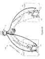
Figure 5A , thebase station 10 may be operable to behave as an L2 switch shown schematically inconfiguration 500. While thebase station 10 sends and receives messages from theCPEs 30 over a single RF Interface (e.g., according to time division duplexing or frequency division duplexing), thebase station 10 can associate eachCPE 30 with alogical port 510 identified, for example, as Lport1, Lport2, Lport3, Lport4,Lport 5.Logical ports 501 may be used to provide radio connectivity to theCPEs 30. Each logical port Lport1, Lport2, Lport3, Lport4, Lport5 may have a number oflogical connections 520 identified, for example, as Lcon1, Lcon2 perCPE 30 that are used to forward traffic over the air. Each logical connection Lcon1, Lcon2 may have a different Quality of Service (QoS), so as to enable thebase station 10 to maintain priority between different applications using the shared air medium in this case, the radio frequency (RF) interface identified generally byreference numeral 402. For example, different QoS may be required for specific types of applications undertaken by thewireless communication system 100, such as for real-time multimedia applications and other applications requiring fixed bit-rate or which are delay sensitive. - When the
base station 10 receives a message from either the RF Interface or Network Interface, thebase station 10 identifies thesource MAC address 320s of the incoming packet. If the MAC address is unknown to thebase station 10, thebase station 10 is operable to create a new entry for the device associated with the source MAC address in the look-up table 12, before forwarding the message to its intended target. Accordingly, thebase station 10 populates the look-up table 12 with MAC addresses identifying CPEs receiving and sending messages in the first communication standard. If the source MAC address is already included within the look-up table 12, thebase station 10 may forward the message without creating a new entry. However, in some embodiments, the base station may first verify and/or update one or more fields associated with the known MAC address, such as for example, updating the agingtime field 340. - Returning to the example depicted in
Figure 4 , an IP packet may be sent by anelectronic device 50 to theCPE 30 for transmission to thebase station 10. From a forwarding point of view, theCPE 30 encapsulates the whole Ethernet frame and sends it to thebase station 10 using the IEEE 802.16E wireless interface shown byreference numeral 401. Once thebase station 10 has received the message, thebase station 10 strips off the 802.16E header and then forwards the frame to the network or to another CPE (not shown) according to the destination MAC address provided in theEthernet header 420 andIP header 430 of the encapsulatedmassage 401. - At the
base station 10, each incoming packet has to be checked against the look-up table 12 before being forwarded. If the destination MAC address is in the look-up table 12, thebase station 10 will forward the packet according to the destination MAC address. If the destination MAC address is not in the look-up table 12 or the packet is a broadcast packet, thebase station 10 will perform broadcast flooding of the packet to all theCPEs 30 and/ornetwork 23 through thenetwork router 20. This behaviour is similar to the behaviour of an L2 switch. It can be implemented efficiently in the TMD scheme of the first communication standard, in order to save the short over-the-air (OTA) resources. - In a preferred embodiment, the
base station 10 has two main functions with regards to scheduling. These include deciding whichlogical port LPORT 510 is served before the other and how much traffic will be sent out. Traffic prioritization in thebase station 10 can be done using a number of mechanisms. In a preferred embodiment, thebase station 10 uses two potential mechanisms. The first mechanism involves a strict priority. In this mechanism, the highest priority traffic is served before any low priority traffic. Priorities are given based on thelogical port 510 and thelogical connection 520 for each of theCPEs 30. In the second mechanism, weighted-fare priority may be used. In this mechanism, the band width across theradio frequency interface 402 is shared relatively according to the weight given to differentlogical ports 510. For example, if there are two logical connections on a particular logical port, one withweight 2 and the other withweight 1, the first may have two-thirds of the available bandwidth and the second may have one-third of the available bandwidth. How much traffic is sent on eachlogical connection 520 of eachlogical port 510 is determined by the committed information rate (CIR) and the maximum information rate (MIR) that are defined by thelogical connection 520. - In the case of multicast connections, each multicast connection has a configurable traffic priority. Thus, for each VLAN communication, traffic can be prioritized over other VLAN traffic. It may also be prioritized over unicast downlink traffic.
-
Figure 5B shows a further preferred embodiment of the present invention. As illustrated inFigure 5B , aconfiguration 505 of thesystem 100 has abase station 10 sending and receiving data to theCPEs 30. In one case, the CPE1 sends a broadcast packet 550 through the first logical port Lport1 to thebase station 10. The broadcast packet 550 is then replicated and broadcast back aspacket 551. It is noted that because the CPEs utilize the sharedradio frequency interface 402, to keep the bandwidth low and increase the efficiency of the system, the pack is not replicated N-1 times for each of the CPEs in order to exclude the originating one. Rather, the replicatedreturn broadcast packet 551 is sent once over the broadcast connection to all of theCPEs 30. It is then incumbent on the originatingCPE 30, in this case CPE1, to drop the returnedpacket 551. This is schematically illustrated, for instance, by the X identified byreference numeral 552 inFigure 5B next to originating CPE1. This efficient treatment of transmitting onereturn packet 551 simultaneously to all of the CPEs and then having the originating CPE recognize that it was the originator of the packet 550 and dropping thereturn packet 551, saves processing time by thebase station 10 and also saves bandwidth over the shared radio frequency interface 502. The originating CPE simply drops thereturn packet 551 in order to avoid wrong learning or out of date learning and thus, lack of communication. The incremental additional processing by the originatingCPE 30 is minor in comparison to the increase in the bandwidth over the sharedinterface 402 and also the decrease in processing time by thebase station 10. - Furthermore, while this approach can be used with broadcast messages, it can also be used with multicast messages which designate a group of CPEs which include the originating CPE, such as in a common VLAN. Therefore, the embodiment illustrated in
Figure 5B is considered non-limiting and could apply to multicast messages to groups ofCPEs 30 ordevice 50 connected to CPEs in different VLANs. It is also understood that while the originating device inFigure 5B is shown to aCPE 30, the invention is not limited in this regard and a device (not shown) connected to aCPE 30 could have originated the packet 550. - Referring now to
Figure 6A ,Figure 6B andFigure 6C , thewireless communication system 100 is depicted according to at least threetopologies network topologies Figure 6A , thesystem 100 has a topology 601 with thebase station 10 connected to one ormore CPEs 30, theindividual CPEs 30 depicted as 30A, 30B, 30C and 30D. Each CPE 30A, 30B, 30C, 30D has at least oneelectronic device 50 associated therewith. The MAC addresses of each of theelectronic devices 50, depicted as 50A, 50B, 50C, 50D, and their associatedCPEs 30 is stored in thebase station 10 within the look-up table 12 as discussed above. Furthermore, thebase station 10 may also store group identifier information, such as Virtual Local Area Network (VLAN) information. In some embodiments, thegroup identifier 330 may be stored within the look-up table 12 containing MAC address information, also stored in thebase station 10. - When a message shown generally by reference numeral 650m is sent from any electronic device 50A, the
base station 10 is operable to forward the message 650m to its intended target, without accessing thenetwork router 20, if thebase station 10 recognizes the intended recipient(s) and has the information stored in the look-up table 12. If thebase station 10 recognizes the intended recipient to be on the network side , thebase station 10 may forward the message 650m to thenetwork router 20 to perform routing. If the recipient of the message is not recognized, thebase stations 10 may flood the packet towards therouter 20 and the rest of the CPEs based on the mechanism described inFigure 5B .Figure 6A ,Figure 6B , andFigure 6C depict various forms of routing according to at least some aspects of the present invention. It should be understood that other embodiments are possible, with the present embodiments not construed as limiting. - By way of example,
Figure 6A illustrates thenetwork topology 600A of awireless communication system 100 in at least one embodiment. The electronic device 50A associated with the CPE 30A is operable to send a unicast message to the electronic device 50B associated with the CPE 30B. The electronic device 50A first sends an IP-based message to the router/L2 switch 40A over a second communication standard, such as for example, an Ethernet connection. The router/L2 switch 40A then forwards the message to the CPE 30A. Once received, the originating CPE 30A then encapsulates all of the Ethernet frame of the message and uplinks a unicast message to thebase station 10 including the MAC address of the target electronic device 50B. Thebase station 10 then strips the wireless header, in a preferred embodiment a 802.16E header, and forwards the message. If thebase station 10 recognizes from its look-up table 12 that the intended target (electronic device 50B) is associated with CPE 30B, thebase station 10 forwards the message to CPE 30B by sending a downlink unicast message, without accessing thenetwork router 20. Thebase station 10 refers to the look-up table 12 to locate switching information and re-encapsulates the message. Referring briefly to the look-up table 12 inFigure 3 , thebase station 10 is operable to locate thedevice entry 302B for the electronic device 50B and then to locate the associatedCPE MAC address 350 for forwarding the message. Once received, the recipient CPE 30B strips the wireless header and forwards the message to the intended electronic device 50B via the router/L2 switch 40B in the second communication standard, in this embodiment Ethernet.. - Referring now to
Figure 7 , amethod 700 for wirelessly communicating multicast messages between a plurality ofCPEs 30 is illustrated according to at least one embodiment of the present invention. With reference toFigure 6A , the method uses thewireless communication system 100 to send an uplink multicast message to thebase station 10 destined to a subset of theCPEs 30 in thewireless communication system 100, based on a group identifier. EachCPE 30 has a unique MAC address and theCPEs 30 andbase station 10 are operable to communicate using a first communication standard that incorporates time division multiplexing over a wireless port. Thebase station 10 and theCPEs 30 are operable to send and receive wireless signals to each other utilizing awireless interface 402 based on a TDM scheme, as defined by the first communication standard such as the WiMAX group of standards. - In
BLOCK 710, an originatingCPE 30 is operable to send an uplink multicast message to thebase station 10 to be sent toother CPEs 30. For example, inFigure 6A , the uplink multicast message shown generally by reference numeral 650m is sent to members of a virtual local area network (VLAN) or other CPE grouping as a multicast message. In some embodiments, as shown inFigure 6A , the multicast message 650m may be sent by the originatingelectronic device 50a, which is operable to send an uplink multicast message to thebase station 10 to be sent to other electronic devices 50 (or CPEs 30) via thebase station 10. - The uplink multicast message 650m may include a group identifier identifying a group of CPEs to receive the uplink multicast message. In
Figure 6A , theelectronic devices group identifer VLAN 10 and the electronic devices 50C, 50D associated with two different CPEs 30C, 30D share thegroup identifier VLAN 20. - In
BLOCK 720, thebase station 10 is operable to receive the uplink multicast message. The message is received over the first communication channel utilizing a TDM scheme. - In response to receiving the uplink multicast message, the
base station 10, inBLOCK 730, is operable to convert the uplink multicast message 650m to a downlink multicast message using the look-up table 12 stored at thebase station 10. As previously discussed, thebase station 10 is operable to store agroup identifier 330, such as a VLAN, for uniquely identifying a group ofCPEs 30 and/or a group ofdevices 50. Thebase station 10 may use thisgroup identifier 330 for determining where to forward the uplink multicast message. If a message from a givenelectronic device 50a, and its associatedCPE 30a, is multicast to its associated VLAN (i.e. VLAN 10), thebase station 10 is able to associate thegroup identifier 330 withspecific CPEs 30 andelectronic devices 50 associated with thegroup identifier 330 based on information contained within the look-up table 12. - In
BLOCK 740, thebase station 10 transmits the downlink multicast message to theCPEs 30, where eachCPE 30 has its MAC address stored in the look-up table 12. Thebase station 10 will create a multicast service flow which will send the message to the identifiedCPEs 30 and/orelectronic devices 50 identified in the multicast message 650m. If the multicast message identifies all of theelectronic devices 50 in a VLAN, such asVLAN 10, the multicast service flow is created inherently as a part of the VLAN in thebase station 10. - In some embodiments, the downlink multicast message is sent to all of the
CPEs 30 inwireless communication system 100, including the originating CPE. In other embodiments, the downlink message is sent to asingle CPE 30 or a subset of all the CPEs 30 associated or registered with thebase station 10. It is understood that while the examples are given with respect to the multicast messages 650m originating from adevice 50a, the invention would work equally if the multicast message 650m originated from aCPE 30 as shown inFigure 5B . - The look-up table 12 stored on the base station contains the MAC addresses of each of the
CPEs 30 associated or registered with thebase station 10. When an uplink message is destined for more than oneCPE 30 registered with thebase station 10, the downlink message may be sent in a single information burst according to the time division multiplexing scheme. For example, the downlink message may be sent in a single TDM timeslot that is assigned to the intended group ofCPEs 30, such as a multicast service flow as described herein. The group ofCPEs 30 may be assigned to the timeslot provided by the scheduling algorithm associated with the first communication standard (i.e. the WiMAX group of standards). Such an approach incorporating the TDM functionality of the first communication channel allows thebase station 10 to send multicast messages efficiently, with reduced end-to-end latency. - In some embodiments, where the originating CPE 30A or electronic device 50A is sending a multicast message to a member of a VLAN which it is not a member (e.g. electronic device 50C, part of VLAN 20), the
base station 10 may not automatically forward the message to its intended recipient, even if it already has switching information stored within the look-up table 12. Instead, thebase station 10 may forward the message to therouter 20. This feature may enhance efficiency and security, as thebase station 10 is capable of efficiently forwarding messages within the same broadcast domain, while simultaneously separating disparate parts (VLANS) of the network. In this manner, thebase station 10 is behaving as a L2 switch, and segregates the different VLANs into different broadcast domains. Furthermore, eachlogical port LPORT 510 shown inFigures 5A and5B and communicating aspecific CPE 30, may be part of a specific VLAN. In other words, when communication to a VLAN that hasdevices 50 connected to CPE1 andCPE 3 ofFigure 5A , for example, the base station may communicate on both LPORT1 and LPORT3, based on thegroup identifier 330 and associated CPE MAC addresses 350 stored in look-up table 12 to decrease bandwidth and processing time. - Referring now to
Figure 6B which illustratestopology 600B, theelectronic devices 50, associated with one ormore CPEs 30, may be organized by group identifier shown generally byreference numeral 330 inFigure 3 , irrespective of how they are connected to the network. For example, electronic devices 50A, 50B, 50C, 50D may be part ofdifferent group identifiers 330, shown inFigure 6B as being part ofdifferent VLANs base station 10 via the same CPEs 30A, 30B. - Accordingly, while in some embodiments, the
electronic devices 50 for aspecific group identifier 330 may be segregated according to the associatedCPE 30, this is not required. In one embodiment, everyelectronic device 50, associated with everyCPE 30 in range or connected to abase station 10, may be associated with thesame group identifier 330. Furthermore, aCPE 30 may have one, many or nogroup identifiers 330 associated with theelectronic devices 50, associated with theCPE 30. EachCPE 30 associated with awireless communication system 100, may have different group identifiers for groups ofelectronic devices 50 associated with thatparticular CPE 30. Different combinations of group identifiers shared betweenCPEs 30 andelectronic devices 50 are possible. - For example, in
Figure 6B , anothernetwork topology 600B is shown having an electronic device 50A, associated withVLAN 10, and an electronic device 50B, associated withVLAN 20, are both associated with the same CPE 30A. Similarly, an electronic device 50C, associated withVLAN 20, and an electronic device 50D, associated withVLAN 10, both of which are associated with the same CPE 30B. Other electronic devices 50 (not shown), associated with other CPEs 30 (not shown), may also be associated with eitherVLAN 10 orVLAN 20. - An
electronic device 50 is operable to send a multicast message to a group of electronic devices 50 (or CPEs 30), even if theelectronic device 50 is not associated with thesame CPE 30, by uniquely identifying the group of electronic devices 50 (or CPEs 30) by using the associatedgroup identifier 330. Any one of theCPEs 30 in the group is operable to specify the group ofCPEs 30 orelectronic devices 50 to receive the multicast message 650 by placing thecorresponding group identifier 330 in the uplink multicast message. - When an uplink multicast message 650 is sent by an electronic device 50A associated with a CPE 30A, the uplink multicast message 650 is sent by the CPE 30A to the
base station 10 over the first communication channel. The originating electronic device 50A or CPE 30A can specify the group ofCPEs 30 to receive the multicast message by placing thecorresponding group identifier 330 in the uplink multicast message. InBLOCK 750, thebase station 10 may transmit the downlink multicast message to the group ofCPEs 30, identified by thegroup identifier 330. - The base station may send the downlink multicast message in a single information burst, including to the CPE 30A or electronic device 50A that originally sent the uplink multicast message. The single information burst may occur over a single TDM timeslot. In other embodiments, the single information burst may occur over a number of sequential timeslots. In any event, the downlink multicast message 650 is sent to the CPEs simultaneously and is received by the appropriate recipient CPEs at the same time, based on the group identifier.
- As illustrated in
Figure 7 , inBLOCK 760, when the originatingCPE 30a orelectronic device 50a that sent the uplink multicast message recognizes that the downlink multicast message corresponds to the uplink multicast message that it sent, the originating CPE 30A or electronic device 50A may drop the received downlink multicast message. In this manner, the originatingCPE 30 is operable to send a multicast message 650 to the entire group identified by the group identifier 33 in the message 650 and thebase station 10 can send the downlink multicast message in a single information burst or TDM timeslot without having to make any modifications to the downlink message. Instead, the message may be sent to the entire group of CPEs, with the originating CPE operable to recognize that a message that it has received from thebase station 10 corresponds to the uplink multicast message 650 that it sent and take appropriate action. For example, the originating CPE may drop the downlink multicast message as illustrated inFigure 5B and discussed above and also shown inBLOCK 760 ofFigure 7 . In other words, thebase station 10 will create a multicast service flow to send the downlink message to all thedevices 50 andCPEs 30 inVLAN 10 inFigure 6A , including the originatingdevice 50a, because this saves processing time and bandwidth. The originatingdevice 50a will then recognize that the received downlink message corresponds to the sent uplink multicast message 650m and disregard or drop the downlink message as discussed above with respect toFigure 5B and shown inBLOCKS Figure 7 . It is understood that while examples are given with respect to multicast messages 650m originating from adevice 50a, the invention would work equally well if the multicast message 650m originated from aCPE 30 as referred to inFigure 7 . - In some embodiments, a
CPE 30 may recognize that the downlink multicast message it has received from thebase station 10 does not need to be forwarded to anyelectronic devices 50 associated with theCPE 30, as the onlyelectronic device 50 associated with the group identifier is the originating electronic device, which sent the uplink multicast message in the first instance. For example, inFigure 6B , if theCPE 30a recognizes that there are no additionalelectronic devices 50 other than the originatingelectronic device 50b associated with the specifiedgroup identifier VLAN 10, theCPE 30a may be operable to drop the downlink multicast message, completely. Alternatively, if there is more than oneelectronic device 50 associated with specifiedgroup identifier VLAN 10, associated with theCPE 30a, theCPE 30a may drop the downlink multicast message for the originatingelectronic device 50b, only, and forward the downlink multicast message to the non-originating electronic devices (not shown). In alternate embodiments, theCPE 30a may continue to forward the downlink multicast message to all theelectronic devices 50b associated with theCPE 30a andgroup identifier VLAN 10, and allow the originatingelectronic device 50b to drop the downlink multicast message, itself. - Referring now to
Figure 6C , yet anothernetwork topology 600C is depicted illustrating twobase stations 10 having a plurality ofelectronic devices 50 associated with one ormore CPEs 30. Thebase stations 10 are connected to each other through anetwork switch 22, such as for example, an Ethernet switch complying with the IEEE 802.3 (Ethernet) series of standards. When messages are destined forCPEs 30 orelectronic devices 50 associated with the same group identifier, thebase stations 10 andnetwork switch 22 are able to work together to forward the uplink multicast messages without accessing therouter 20. - As a layer 2 (L2) device in the Open Systems Interconnection model (OSI model), the
network switch 22 is operable to learn the MAC addresses of devices connected to the network switch's 22 physical Ethernet ports (not shown). In order to support L2 tagged multicast traffic, thewireless communication system 100 is operable to define the relevant VLANs and associate therelevant CPEs 30 with each VLAN. No extra configuration or provisioning is required, as the multicast service flow is created inherently as part of VLAN creation in thebase station 10. - Furthermore, no signalling is involved or required. Once tagged traffic is recognized as multicast traffic according to the required message frame structure incorporating the group identifier, the tagged traffic is replicated and sent to all the CPEs 30 that are subscribed to the VLAN. Accordingly, once associated with a specific VLAN, tagged traffic specific to that VLAN will be associated with the relevant multicast service flow.
- In situations where the message is untagged, the L2 message may be forwarded to all the
CPEs 30 within thewireless communication system 10 over a broadcast connection. For thewireless communication system 100 to act in multicast mode, ensuring that a multicast message reaches every possibleelectronic device 50 orCPE 30 associated with a group identifier, everyCPE 30 in thewireless communication system 100 with members associated with the group identifier must be in the look-up table 12 stored in thebase station 10. Alternatively, the group identifier will not be recognized by thebase station 10 at all (i.e., nobase station 10 with either anelectronic device 50 orCPE 30 is indexed in the look-up table 12). In this manner, when receiving an uplink multicast message, thebase station 10 will correctly forward the multicast message to all thebase stations 10 having members associated with the group identifier or will not recognize the group identifier at all, and will resort to broadcasting the uplink multicast message to allnetwork devices base station 10 receiving the uplink multicast message will not receive the multicast message. - To the extent that a patentee may act as its own lexicographer under applicable law, it is hereby further directed that all words appearing in the claims section, except for the above defined words, shall take on their ordinary, plain and accustomed meanings (as generally evidenced, inter alia, by dictionaries and/or technical lexicons), and shall not be considered to be specially defined in this specification. Notwithstanding this limitation on the inference of "special definitions," the specification may be used to evidence the appropriate, ordinary, plain and accustomed meanings (as generally evidenced, inter alia, by dictionaries and/or technical lexicons), in the situation where a word or term used in the claims has more than one pre-established meaning and the specification is helpful in choosing between the alternatives.
- It is understood that reference has been made throughout the disclosure and claims to the MAC address for various electronic devices including the consumer premises equipment. It is understood that the MAC address is being used as a unique identifier for the corresponding electronic device. However, the invention is not limited to use of the MAC addresses for this purpose. Rather, any unique identifier can be used as an address to uniquely identify the CPEs and other electronic devices and it is understood that the invention is not limited to use of MAC addresses for this purpose.
- It will be understood that, although various features of the invention have been described with respect to one or another of the embodiments of the invention, the various features and embodiments of the invention may be combined or used in conjunction with other features and embodiments of the invention as described and illustrated herein.
- Although this disclosure has described and illustrated certain preferred embodiments of the invention, it is to be understood that the invention is not restricted to these particular embodiments. Rather, the invention includes all embodiments, which are functional, electrical or mechanical equivalents of the specific embodiments and features that have been described and illustrated herein.
- The preferred embodiments of the invention are specified by the following paragraphs:
- 1. A wireless communication system comprising:
- a plurality of consumer premises equipments (CPEs) for sending and receiving wireless signals in a first communication standard using time division multiplexing (TDM), each CPE having a unique MAC address;
- a base station having a wireless port for sending and receiving wireless signals to each of the plurality of CPEs in the first communication standard and using TDM, said base station having stored therein a look-up table containing the MAC addresses of each of the plurality of CPEs;
- wherein any one of the plurality of CPEs can uplink a multicast message to the base station to be sent to the CPEs; and
- wherein in response to receiving the uplink multicast message, the base station sends a downlink multicast message to the CPEs having their MAC addresses stored in the look-up table and identified in the uplink multicast message.
- 2. The system of
para 1 wherein the base station sends the downlink multicast message to the CPEs having their MAC addresses stored in the look-up table in a single information burst. - 3. The system of
para 1 wherein the base station sends the downlink multicast message to the CPEs having their MAC addresses stored in the look-up table in a single TDM timeslot. - 4. The system of
para 1 wherein the base station creates a multicast service flow to send the downlink multicast message in a single information burst to the CPEs identified in the uplink multicast message. - 5. The system of
para 1 wherein the base station transmits the downlink multicast message, in a single information burst, to all of the CPEs having their MAC addresses stored in a look-up table including the one of the plurality of CPEs that originated the uplink multicast message. - 6. The system as specified in
para 5 wherein when the originating CPE that sent the uplink multicast message recognizes that the downlink multicast message corresponds to the uplink multicast message that it sent, the originating CPE drops the received downlink multicast message. - 7. The system as specified in
para 1 wherein the base station further comprises a group identifier for each CPE, said group identifier uniquely identifying a group of CPEs;
and
wherein the any one of the originating CPEs can specify a group of CPEs to receive the multicast message by placing the corresponding group identifier in the uplink multicast message. - 8. The system of para 7 wherein the base station transmits the downlink multicast message to the group of CPEs identified by the group identifier in the single information burst, including the one of the plurality of CPEs that originated the uplink multicast message.
- 9. The system as specified in para 8 wherein when the originating CPE recognizes that the downlink multicast message corresponds to the uplink multicast message that it sent, the originating CPE drops the received downlink multicast message.
- 10. The system of para 7 wherein the base station creates a multicast service flow to send the downlink multicast message in a single information burst to the CPEs identified by the corresponding group identifier.
- 11. The system as specified in para 7 wherein at least one CPE has one or more electronic devices associated therewith, and, each electronic device has a MAC address uniquely identifying the electronic device associated with the CPE.
- 12. The system as specified in
para 11 wherein the look-up table stored in the base station further contains the MAC address of each electronic device and its associated CPE. - 13. The system as specified in
para 11 wherein the electronic devices communicate with the CPE using a second communication standard selected from the group of communication standards consisting of IEEE 802.11, IEEE 802.3 and IEEE 802.1Q. - 14. The system as specified in
para 11 wherein at least one electronic device associated with a CPE has a different group identifier than another one of the electronic devices associated with the same CPE. - 15. The system as specified in
para 1 wherein the base station monitors the messages sent and received on the wireless port and populates the look-up table with MAC addresses identifying CPEs receiving and sending messages in the first communication standard. - 16. The system as specified in para 7 wherein the base station has a second port for sending and receiving signals in a second communication standard and sending the messages to the CPEs in the first communication standard; and
wherein the base station monitors the messages to and from the wired port and the wireless port to populate the look-up table. - 17. The system as specified in para 16 wherein the second port is a wired port and the second communication standard is selected from the group of wired communication standards consisting of IEEE 802.3 (Ethernet), IEEE 802.1Q (VLAN Tagging).
- 18. The system as specified in
para 1 wherein the first communication standard complies with the IEEE 802.16 Standard (WiMAX). - 19. A method of wirelessly communicating multicast messages between a plurality of consumer premises equipment (CPEs) in a first communication standard using Time Division Multiplexing (TDM), each of said CPEs having a unique MAC address, said method comprising:
- sending, from an originating CPE of the plurality of CPEs, an uplink multicast message to a base station, said base station having a wireless port for sending and receiving wireless signals to each of the plurality of CPEs in the first communication standard and using TDM, said base station also having stored therein a look-up table containing the MAC addresses of each of the plurality of CPEs;
- receiving, at the base station, the uplink multicast message;
- converting, at the base station, the uplink multicast message to a downlink multicast transmit message using the look-up table stored at the base station; and
- transmitting, by the base station, the downlink multicast message to the CPEs having their MAC addresses stored in the look-up table and identified in the uplink multicast message.
- 20. The method of para 19 wherein the step of transmitting, by the base station, the downlink multicast message to the plurality of CPEs, includes transmitting the downlink multicast message to all of the CPEs having their MAC addresses stored in a look-up table including the originating CPE.
- 21. The method as specified in
para 20 further comprising:- recognizing, at the originating CPE , that the downlink multicast message corresponds to the uplink multicast message previously sent by the originating CPE; and
- dropping, by the originating CPE, the received downlink multicast message.
- 22. The method as specified in para 19 further comprising:
- monitoring, by the base station, the messages sent and received on the wireless port to determine the MAC addresses of CPEs receiving and sending messages in the first communication standard; and
- populating the look-up table stored at the base station with MAC addresses identifying CPEs receiving and sending messages in the first communication standard.
- 23. The method as specified in para 19 wherein the base station comprises a wired port for sending and receiving signals in a second communication standard and sending the messages to the CPEs in the first communication standard; and
wherein the method further comprises:- monitoring, by the base station, the messages sent and received on the wireless port and the wired port to determine the MAC addresses of the CPEs receiving and sending messages in the first communication standard; and
- populating the look-up table stored at the base station with MAC addresses identifying CPEs receiving and sending messages in the first communication standard.
- 24. The method as specified in para 19 wherein the look up table stored at the base station comprises a group identifier for each CPE, said group identifier uniquely identifying a group of CPEs; and
wherein the originating CPE can specify a specific group of CPEs to receive the multicast message by placing the corresponding group identifier in the uplink multicast message. - 25. The method as specified in para 24 wherein at least one CPE has one or more electronic devices associated therewith, each electronic device having a MAC address uniquely identifying the electronic device associated with the CPE.
- 26. The method of para 25 wherein at least one electronic device associated with a CPE has a different group identifier than another one of the electronic devices associated with the same CPE.
- 27. The method as specified in para 19 wherein the second wired communication standard is selected from the group consisting of IEEE 802.3 (Ethernet), IEEE 802.1Q (VLAN Tagging).
Claims (15)
- A wireless communication system comprising:a plurality of consumer premises equipments (CPEs) for sending and receiving wireless signals in a first communication standard using time division multiplexing (TDM), each CPE having a unique MAC address;a base station having a wireless port for sending and receiving wireless signals to each of the plurality of CPEs in the first communication standard and using TDM, said base station having stored therein a look-up table containing the MAC addresses of each of the plurality of CPEs;wherein any one of the plurality of CPEs can uplink a multicast message to the base station to be sent to the CPEs; andwherein in response to receiving the uplink multicast message, the base station sends a downlink multicast message to the CPEs having their MAC addresses stored in the look-up table and identified in the uplink multicast message.
- The system of claim 1 wherein the base station sends the downlink multicast message to the CPEs having their MAC addresses stored in the look-up table in a single information burst or in a single TDM timeslot.
- The system of claim 1 wherein the base station creates a multicast service flow to send the downlink multicast message in a single information burst to the CPEs identified in the uplink multicast message.
- The system as defined in claim 1 wherein the lookup table stored at the base station further comprises a group identifier for each CPE, said group identifier uniquely identifying a group of CPEs; and
wherein the any one of the originating CPEs can specify a group of CPEs to receive the multicast message by placing the corresponding group identifier in the uplink multicast message. - The system of claim 4 wherein the base station transmits the downlink multicast message to the group of CPEs identified by the group identifier in the single information burst, including the one of the plurality of CPEs that originated the uplink multicast message.
- The system as defined in claim 5 wherein when the originating CPE recognizes that the downlink multicast message corresponds to the uplink multicast message that it sent, the originating CPE drops the received downlink multicast message.
- The system of claim 4 wherein the base station creates a multicast service flow to send the downlink multicast message in a single information burst to the CPEs identified by the corresponding group identifier.
- The system as defined in claim 4 wherein at least one CPE has one or more electronic devices associated therewith, and, each electronic device has a MAC address uniquely identifying the electronic device associated with the CPE, wherein, preferably, the electronic devices communicate with the CPE using a second communication standard selected from the group of wired communication standards consisting of IEEE 802.3 (Ethernet), IEEE 802.1Q (VLAN Tagging).
- The system as defined in claim 8 wherein the look-up table stored in the base station further contains the MAC address of each electronic device and its associated CPE.
- The system as defined in claim 7 wherein at least one electronic device associated with a CPE has a different group identifier than another one of the electronic devices associated with the same CPE.
- The system as defined in claim 1 wherein the base station has a second port for sending and receiving signals in a second communication standard and sending the messages to the CPEs in the first communication standard; and
wherein the base station monitors the messages to and from the wired port and the wireless port to populate the look-up table, wherein, preferably, the second port is a wired port and the second communication standard is selected from the group of wired communication standards consisting of IEEE 802.3 (Ethernet), IEEE 802.1Q (VLAN Tagging). - A method of wirelessly communicating multicast messages between a plurality of consumer premises equipment (CPEs) in a first communication standard using Time Division Multiplexing (TDM), each of said CPEs having a unique MAC address, said method comprising:sending, from an originating CPE of the plurality of CPEs, an uplink multicast message to a base station, said base station having a wireless port for sending and receiving wireless signals to each of the plurality of CPEs in the first communication standard and using TDM, said base station also having stored therein a look-up table containing the MAC addresses of each of the plurality of CPEs;receiving, at the base station, the uplink multicast message;converting, at the base station, the uplink multicast message to a downlink multicast transmit message using the look-up table stored at the base station; andtransmitting, by the base station, the downlink multicast message to the CPEs having their MAC addresses stored in the look-up table and identified in the uplink multicast message.
- The method of claim 12 wherein the step of transmitting by the base station, preferably in a single information burst, the downlink multicast message to the plurality of CPEs, includes transmitting the downlink multicast message to all of the CPEs having their MAC addresses stored in a look-up table including the originating CPE.
- The method as defined in claim 13 further comprising:recognizing, at the originating CPE , that the downlink multicast message corresponds to the uplink multicast message previously sent by the originating CPE; anddropping, by the originating CPE, the received downlink multicast message.
- The method as defined in claim 12 either further comprising the steps of:monitoring, by the base station, the messages sent and received on the wireless port to determine the MAC addresses of CPEs receiving and sending messages in the first communication standard; andpopulating the look-up table stored at the base station with MAC addresses identifying CPEs receiving and sending messages in the first communication standard,or, in case the base station comprises a wired port for sending and receiving signals in a second communication standard and sending the messages to the CPEs in the first communication standard, further comprising the steps of:wherein the method further comprises:monitoring, by the base station, the messages sent and received on the wireless port and the wired port to determine the MAC addresses of the CPEs receiving and sending messages in the first communication standard; andpopulating the look-up table stored at the base station with MAC addresses identifying CPEs receiving and sending messages in the first communication standard.
Applications Claiming Priority (1)
| Application Number | Priority Date | Filing Date | Title |
|---|---|---|---|
| CA2732181A CA2732181C (en) | 2011-02-18 | 2011-02-18 | Stand alone wimax system and method |
Publications (3)
| Publication Number | Publication Date |
|---|---|
| EP2490465A2 true EP2490465A2 (en) | 2012-08-22 |
| EP2490465A3 EP2490465A3 (en) | 2014-11-26 |
| EP2490465B1 EP2490465B1 (en) | 2021-07-28 |
Family
ID=44645004
Family Applications (1)
| Application Number | Title | Priority Date | Filing Date |
|---|---|---|---|
| EP11179102.6A Active EP2490465B1 (en) | 2011-02-18 | 2011-08-26 | Stand alone WiMAX system and method |
Country Status (5)
| Country | Link |
|---|---|
| US (1) | US8570987B2 (en) |
| EP (1) | EP2490465B1 (en) |
| CN (1) | CN102647793B (en) |
| CA (1) | CA2732181C (en) |
| IL (1) | IL213462A (en) |
Cited By (2)
| Publication number | Priority date | Publication date | Assignee | Title |
|---|---|---|---|---|
| EP2876972A4 (en) * | 2012-09-07 | 2015-07-01 | Huawei Tech Co Ltd | Air interface transmission method and relevant device and system |
| EP3079315A1 (en) * | 2015-04-10 | 2016-10-12 | Lenovo (Singapore) Pte. Ltd. | Bandwidth prioritization |
Families Citing this family (11)
| Publication number | Priority date | Publication date | Assignee | Title |
|---|---|---|---|---|
| CN103907320A (en) * | 2011-09-09 | 2014-07-02 | 瑞典爱立信有限公司 | Protection group switching for circuit emulaton |
| US20130132745A1 (en) * | 2011-11-22 | 2013-05-23 | Cisco Technology Inc. | System and method for network enabled wake for networks |
| US10588101B2 (en) * | 2012-01-06 | 2020-03-10 | Qualcomm Incorporated | Long term evoluton (LTE) user equipment relays having a licensed wireless or wired backhaul link and an unlicensed access link |
| US9160739B2 (en) * | 2012-05-21 | 2015-10-13 | Invisible Text, LLC | Secure data transmission system |
| US9923733B2 (en) * | 2012-08-28 | 2018-03-20 | Mitsubishi Electric Corporation | Network system and communication apparatus for performing communication among networks having different VLAN settings |
| CN106982178B (en) * | 2016-01-15 | 2020-05-01 | 中国移动通信集团公司 | Resource allocation method, network management equipment and system |
| US10235516B2 (en) | 2016-05-10 | 2019-03-19 | Cisco Technology, Inc. | Method for authenticating a networked endpoint using a physical (power) challenge |
| CN107786946B (en) * | 2016-08-30 | 2020-02-07 | 大唐移动通信设备有限公司 | Cluster service data processing method and cluster base station |
| US11006311B2 (en) * | 2017-05-16 | 2021-05-11 | Qualcomm Incorporated | Ethernet over cellular |
| US11856489B2 (en) * | 2019-08-08 | 2023-12-26 | Qualcomm Incorporated | Uplink broadcast/multicast packet processing |
| SE2151546A1 (en) * | 2021-12-16 | 2023-06-17 | Assa Abloy Ab | Routing data in a communication network |
Family Cites Families (9)
| Publication number | Priority date | Publication date | Assignee | Title |
|---|---|---|---|---|
| JP3628250B2 (en) * | 2000-11-17 | 2005-03-09 | 株式会社東芝 | Registration / authentication method used in a wireless communication system |
| US6901058B2 (en) * | 2002-08-22 | 2005-05-31 | Nokia Corporation | System and method for enabling multicast in a CDMA network |
| US7424007B2 (en) * | 2004-05-12 | 2008-09-09 | Cisco Technology, Inc. | Power-save method for 802.11 multicast paging applications |
| US7616746B2 (en) * | 2004-08-13 | 2009-11-10 | Qualcomm Incorporated | Methods and apparatus for tracking and charging for communications resource reallocation |
| US8081600B2 (en) * | 2005-07-29 | 2011-12-20 | Nextel Communications Inc. | Systems and methods for communicating between base stations and wireless stations |
| KR101210340B1 (en) * | 2005-10-13 | 2012-12-10 | 삼성전자주식회사 | Method and Apparatus for Supporting Multicast/Broadcast in Wireless Communication System |
| EP2199818B1 (en) * | 2008-12-19 | 2019-02-20 | Koninklijke KPN N.V. | Method of determining a location of a mobile device |
| CA2656660C (en) * | 2009-02-27 | 2016-11-08 | Ruggedcom Inc. | Client/bridge and method and system for using same |
| US8654661B2 (en) * | 2009-05-04 | 2014-02-18 | Industrial Technology Research Institute | Method and apparatus for multicast and broadcast retransmission in wireless communication systems |
-
2011
- 2011-02-18 CA CA2732181A patent/CA2732181C/en active Active
- 2011-06-09 IL IL213462A patent/IL213462A/en active IP Right Grant
- 2011-06-09 US US13/156,527 patent/US8570987B2/en active Active
- 2011-08-26 EP EP11179102.6A patent/EP2490465B1/en active Active
- 2011-09-23 CN CN201110291084.5A patent/CN102647793B/en active Active
Non-Patent Citations (1)
| Title |
|---|
| None |
Cited By (2)
| Publication number | Priority date | Publication date | Assignee | Title |
|---|---|---|---|---|
| EP2876972A4 (en) * | 2012-09-07 | 2015-07-01 | Huawei Tech Co Ltd | Air interface transmission method and relevant device and system |
| EP3079315A1 (en) * | 2015-04-10 | 2016-10-12 | Lenovo (Singapore) Pte. Ltd. | Bandwidth prioritization |
Also Published As
| Publication number | Publication date |
|---|---|
| CN102647793B (en) | 2016-12-28 |
| IL213462A (en) | 2015-07-30 |
| CA2732181C (en) | 2017-08-29 |
| CA2732181A1 (en) | 2012-08-18 |
| IL213462A0 (en) | 2011-08-31 |
| CN102647793A (en) | 2012-08-22 |
| US20120213085A1 (en) | 2012-08-23 |
| EP2490465B1 (en) | 2021-07-28 |
| EP2490465A3 (en) | 2014-11-26 |
| US8570987B2 (en) | 2013-10-29 |
Similar Documents
| Publication | Publication Date | Title |
|---|---|---|
| CA2732181C (en) | Stand alone wimax system and method | |
| US20200128580A1 (en) | Method for selecting of sidelink grant for a d2d ue in a d2d communication system and device therefor | |
| US9648585B2 (en) | Data transmission method and device | |
| US20170048903A1 (en) | Method for performing a logical channel prioritization in a d2d communication system and device therefor | |
| US8862170B2 (en) | Cloud communication center system and method for processing data in a cloud communication system | |
| JP2018527800A (en) | Method and apparatus for performing buffer status reporting in a D2D communication system | |
| CN109155904B (en) | Apparatus and method for supporting local Multimedia Broadcast Multicast Service (MBMS) distribution | |
| JP2017538374A (en) | Method and apparatus for canceling scheduling request triggered by side link buffer status report in D2D communication system | |
| US9338769B1 (en) | Method of scheduling communication in a wireless communication network | |
| US20180035398A1 (en) | Method for acquiring synchronization in a communication system and device therefor | |
| WO2018000220A1 (en) | Data transmission method, apparatus and system | |
| Rakesh et al. | A survey of mobile WiMAX IEEE 802.16 m standard | |
| EP3959831A1 (en) | Multi-hop wireless relay support | |
| CN112470437A (en) | Device to device forwarding | |
| US20110158155A1 (en) | Apparatus and method for managing quality of service in broadband wireless communication system with multiple hop relay communication | |
| TW202037210A (en) | Sidelink synchronization methods for v2x in nr | |
| US11064395B1 (en) | Ensuring quality of service at a cell site router | |
| Chuang et al. | STASH: SDN-based trajectory-aware seamless handover scheme with multiple antennas in ultra-dense smallcell networks | |
| US9736719B2 (en) | Adaptive resource allocation in congested wireless local area network deployment | |
| US20090161640A1 (en) | Mobile Wireless Access Router for Separately Controlling Traffic Signal and Control Signal | |
| US9832773B1 (en) | Method of scheduling communication in a wireless communication network | |
| Sarraf et al. | Quality of service mapping between UMTS, WiMAX and IP-based network in Heterogeneous Wireless Networks | |
| US9462601B1 (en) | Method of scheduling communication in a wireless communication network | |
| US9439203B1 (en) | Method of scheduling communication in a wireless communication network | |
| Ksentini | IPv6 over IEEE 802.16 (WiMAX) Networks: Facts and Challenges. |
Legal Events
| Date | Code | Title | Description |
|---|---|---|---|
| PUAI | Public reference made under article 153(3) epc to a published international application that has entered the european phase |
Free format text: ORIGINAL CODE: 0009012 |
|
| AK | Designated contracting states |
Kind code of ref document: A2 Designated state(s): AL AT BE BG CH CY CZ DE DK EE ES FI FR GB GR HR HU IE IS IT LI LT LU LV MC MK MT NL NO PL PT RO RS SE SI SK SM TR |
|
| AX | Request for extension of the european patent |
Extension state: BA ME |
|
| PUAL | Search report despatched |
Free format text: ORIGINAL CODE: 0009013 |
|
| AK | Designated contracting states |
Kind code of ref document: A3 Designated state(s): AL AT BE BG CH CY CZ DE DK EE ES FI FR GB GR HR HU IE IS IT LI LT LU LV MC MK MT NL NO PL PT RO RS SE SI SK SM TR |
|
| AX | Request for extension of the european patent |
Extension state: BA ME |
|
| RIC1 | Information provided on ipc code assigned before grant |
Ipc: H04W 4/06 20090101AFI20141022BHEP |
|
| 17P | Request for examination filed |
Effective date: 20150513 |
|
| RBV | Designated contracting states (corrected) |
Designated state(s): AL AT BE BG CH CY CZ DE DK EE ES FI FR GB GR HR HU IE IS IT LI LT LU LV MC MK MT NL NO PL PT RO RS SE SI SK SM TR |
|
| RAP1 | Party data changed (applicant data changed or rights of an application transferred) |
Owner name: SIEMENS ISRAEL LTD. |
|
| STAA | Information on the status of an ep patent application or granted ep patent |
Free format text: STATUS: EXAMINATION IS IN PROGRESS |
|
| 17Q | First examination report despatched |
Effective date: 20180713 |
|
| STAA | Information on the status of an ep patent application or granted ep patent |
Free format text: STATUS: EXAMINATION IS IN PROGRESS |
|
| REG | Reference to a national code |
Ref country code: DE Ref legal event code: R079 Ref document number: 602011071444 Country of ref document: DE Free format text: PREVIOUS MAIN CLASS: H04W0004060000 Ipc: H04L0012180000 |
|
| GRAP | Despatch of communication of intention to grant a patent |
Free format text: ORIGINAL CODE: EPIDOSNIGR1 |
|
| STAA | Information on the status of an ep patent application or granted ep patent |
Free format text: STATUS: GRANT OF PATENT IS INTENDED |
|
| RIC1 | Information provided on ipc code assigned before grant |
Ipc: H04L 12/18 20060101AFI20210312BHEP Ipc: H04W 4/06 20090101ALI20210312BHEP Ipc: H04W 72/00 20090101ALI20210312BHEP Ipc: H04W 76/40 20180101ALI20210312BHEP Ipc: H04L 29/12 20060101ALN20210312BHEP Ipc: H04W 4/12 20090101ALN20210312BHEP |
|
| INTG | Intention to grant announced |
Effective date: 20210421 |
|
| GRAS | Grant fee paid |
Free format text: ORIGINAL CODE: EPIDOSNIGR3 |
|
| GRAA | (expected) grant |
Free format text: ORIGINAL CODE: 0009210 |
|
| STAA | Information on the status of an ep patent application or granted ep patent |
Free format text: STATUS: THE PATENT HAS BEEN GRANTED |
|
| AK | Designated contracting states |
Kind code of ref document: B1 Designated state(s): AL AT BE BG CH CY CZ DE DK EE ES FI FR GB GR HR HU IE IS IT LI LT LU LV MC MK MT NL NO PL PT RO RS SE SI SK SM TR |
|
| REG | Reference to a national code |
Ref country code: GB Ref legal event code: FG4D |
|
| REG | Reference to a national code |
Ref country code: CH Ref legal event code: EP |
|
| REG | Reference to a national code |
Ref country code: DE Ref legal event code: R096 Ref document number: 602011071444 Country of ref document: DE |
|
| REG | Reference to a national code |
Ref country code: AT Ref legal event code: REF Ref document number: 1415719 Country of ref document: AT Kind code of ref document: T Effective date: 20210815 |
|
| REG | Reference to a national code |
Ref country code: IE Ref legal event code: FG4D |
|
| REG | Reference to a national code |
Ref country code: LT Ref legal event code: MG9D |
|
| REG | Reference to a national code |
Ref country code: NL Ref legal event code: MP Effective date: 20210728 |
|
| REG | Reference to a national code |
Ref country code: AT Ref legal event code: MK05 Ref document number: 1415719 Country of ref document: AT Kind code of ref document: T Effective date: 20210728 |
|
| PG25 | Lapsed in a contracting state [announced via postgrant information from national office to epo] |
Ref country code: LT Free format text: LAPSE BECAUSE OF FAILURE TO SUBMIT A TRANSLATION OF THE DESCRIPTION OR TO PAY THE FEE WITHIN THE PRESCRIBED TIME-LIMIT Effective date: 20210728 Ref country code: BG Free format text: LAPSE BECAUSE OF FAILURE TO SUBMIT A TRANSLATION OF THE DESCRIPTION OR TO PAY THE FEE WITHIN THE PRESCRIBED TIME-LIMIT Effective date: 20211028 Ref country code: AT Free format text: LAPSE BECAUSE OF FAILURE TO SUBMIT A TRANSLATION OF THE DESCRIPTION OR TO PAY THE FEE WITHIN THE PRESCRIBED TIME-LIMIT Effective date: 20210728 Ref country code: RS Free format text: LAPSE BECAUSE OF FAILURE TO SUBMIT A TRANSLATION OF THE DESCRIPTION OR TO PAY THE FEE WITHIN THE PRESCRIBED TIME-LIMIT Effective date: 20210728 Ref country code: PT Free format text: LAPSE BECAUSE OF FAILURE TO SUBMIT A TRANSLATION OF THE DESCRIPTION OR TO PAY THE FEE WITHIN THE PRESCRIBED TIME-LIMIT Effective date: 20211129 Ref country code: NL Free format text: LAPSE BECAUSE OF FAILURE TO SUBMIT A TRANSLATION OF THE DESCRIPTION OR TO PAY THE FEE WITHIN THE PRESCRIBED TIME-LIMIT Effective date: 20210728 Ref country code: NO Free format text: LAPSE BECAUSE OF FAILURE TO SUBMIT A TRANSLATION OF THE DESCRIPTION OR TO PAY THE FEE WITHIN THE PRESCRIBED TIME-LIMIT Effective date: 20211028 Ref country code: FI Free format text: LAPSE BECAUSE OF FAILURE TO SUBMIT A TRANSLATION OF THE DESCRIPTION OR TO PAY THE FEE WITHIN THE PRESCRIBED TIME-LIMIT Effective date: 20210728 Ref country code: ES Free format text: LAPSE BECAUSE OF FAILURE TO SUBMIT A TRANSLATION OF THE DESCRIPTION OR TO PAY THE FEE WITHIN THE PRESCRIBED TIME-LIMIT Effective date: 20210728 Ref country code: SE Free format text: LAPSE BECAUSE OF FAILURE TO SUBMIT A TRANSLATION OF THE DESCRIPTION OR TO PAY THE FEE WITHIN THE PRESCRIBED TIME-LIMIT Effective date: 20210728 Ref country code: HR Free format text: LAPSE BECAUSE OF FAILURE TO SUBMIT A TRANSLATION OF THE DESCRIPTION OR TO PAY THE FEE WITHIN THE PRESCRIBED TIME-LIMIT Effective date: 20210728 |
|
| PG25 | Lapsed in a contracting state [announced via postgrant information from national office to epo] |
Ref country code: PL Free format text: LAPSE BECAUSE OF FAILURE TO SUBMIT A TRANSLATION OF THE DESCRIPTION OR TO PAY THE FEE WITHIN THE PRESCRIBED TIME-LIMIT Effective date: 20210728 Ref country code: LV Free format text: LAPSE BECAUSE OF FAILURE TO SUBMIT A TRANSLATION OF THE DESCRIPTION OR TO PAY THE FEE WITHIN THE PRESCRIBED TIME-LIMIT Effective date: 20210728 Ref country code: GR Free format text: LAPSE BECAUSE OF FAILURE TO SUBMIT A TRANSLATION OF THE DESCRIPTION OR TO PAY THE FEE WITHIN THE PRESCRIBED TIME-LIMIT Effective date: 20211029 |
|
| REG | Reference to a national code |
Ref country code: CH Ref legal event code: PL |
|
| REG | Reference to a national code |
Ref country code: BE Ref legal event code: MM Effective date: 20210831 |
|
| PG25 | Lapsed in a contracting state [announced via postgrant information from national office to epo] |
Ref country code: LI Free format text: LAPSE BECAUSE OF NON-PAYMENT OF DUE FEES Effective date: 20210831 Ref country code: DK Free format text: LAPSE BECAUSE OF FAILURE TO SUBMIT A TRANSLATION OF THE DESCRIPTION OR TO PAY THE FEE WITHIN THE PRESCRIBED TIME-LIMIT Effective date: 20210728 Ref country code: CH Free format text: LAPSE BECAUSE OF NON-PAYMENT OF DUE FEES Effective date: 20210831 |
|
| REG | Reference to a national code |
Ref country code: DE Ref legal event code: R097 Ref document number: 602011071444 Country of ref document: DE |
|
| PG25 | Lapsed in a contracting state [announced via postgrant information from national office to epo] |
Ref country code: SM Free format text: LAPSE BECAUSE OF FAILURE TO SUBMIT A TRANSLATION OF THE DESCRIPTION OR TO PAY THE FEE WITHIN THE PRESCRIBED TIME-LIMIT Effective date: 20210728 Ref country code: SK Free format text: LAPSE BECAUSE OF FAILURE TO SUBMIT A TRANSLATION OF THE DESCRIPTION OR TO PAY THE FEE WITHIN THE PRESCRIBED TIME-LIMIT Effective date: 20210728 Ref country code: RO Free format text: LAPSE BECAUSE OF FAILURE TO SUBMIT A TRANSLATION OF THE DESCRIPTION OR TO PAY THE FEE WITHIN THE PRESCRIBED TIME-LIMIT Effective date: 20210728 Ref country code: MC Free format text: LAPSE BECAUSE OF FAILURE TO SUBMIT A TRANSLATION OF THE DESCRIPTION OR TO PAY THE FEE WITHIN THE PRESCRIBED TIME-LIMIT Effective date: 20210728 Ref country code: LU Free format text: LAPSE BECAUSE OF NON-PAYMENT OF DUE FEES Effective date: 20210826 Ref country code: EE Free format text: LAPSE BECAUSE OF FAILURE TO SUBMIT A TRANSLATION OF THE DESCRIPTION OR TO PAY THE FEE WITHIN THE PRESCRIBED TIME-LIMIT Effective date: 20210728 Ref country code: CZ Free format text: LAPSE BECAUSE OF FAILURE TO SUBMIT A TRANSLATION OF THE DESCRIPTION OR TO PAY THE FEE WITHIN THE PRESCRIBED TIME-LIMIT Effective date: 20210728 Ref country code: AL Free format text: LAPSE BECAUSE OF FAILURE TO SUBMIT A TRANSLATION OF THE DESCRIPTION OR TO PAY THE FEE WITHIN THE PRESCRIBED TIME-LIMIT Effective date: 20210728 |
|
| PLBE | No opposition filed within time limit |
Free format text: ORIGINAL CODE: 0009261 |
|
| STAA | Information on the status of an ep patent application or granted ep patent |
Free format text: STATUS: NO OPPOSITION FILED WITHIN TIME LIMIT |
|
| 26N | No opposition filed |
Effective date: 20220429 |
|
| PG25 | Lapsed in a contracting state [announced via postgrant information from national office to epo] |
Ref country code: IT Free format text: LAPSE BECAUSE OF FAILURE TO SUBMIT A TRANSLATION OF THE DESCRIPTION OR TO PAY THE FEE WITHIN THE PRESCRIBED TIME-LIMIT Effective date: 20210728 Ref country code: IE Free format text: LAPSE BECAUSE OF NON-PAYMENT OF DUE FEES Effective date: 20210826 Ref country code: BE Free format text: LAPSE BECAUSE OF NON-PAYMENT OF DUE FEES Effective date: 20210831 |
|
| PG25 | Lapsed in a contracting state [announced via postgrant information from national office to epo] |
Ref country code: HU Free format text: LAPSE BECAUSE OF FAILURE TO SUBMIT A TRANSLATION OF THE DESCRIPTION OR TO PAY THE FEE WITHIN THE PRESCRIBED TIME-LIMIT; INVALID AB INITIO Effective date: 20110826 Ref country code: CY Free format text: LAPSE BECAUSE OF FAILURE TO SUBMIT A TRANSLATION OF THE DESCRIPTION OR TO PAY THE FEE WITHIN THE PRESCRIBED TIME-LIMIT Effective date: 20210728 |
|
| PGFP | Annual fee paid to national office [announced via postgrant information from national office to epo] |
Ref country code: DE Payment date: 20231019 Year of fee payment: 13 |
|
| PG25 | Lapsed in a contracting state [announced via postgrant information from national office to epo] |
Ref country code: MK Free format text: LAPSE BECAUSE OF FAILURE TO SUBMIT A TRANSLATION OF THE DESCRIPTION OR TO PAY THE FEE WITHIN THE PRESCRIBED TIME-LIMIT Effective date: 20210728 |
|
| PG25 | Lapsed in a contracting state [announced via postgrant information from national office to epo] |
Ref country code: TR Free format text: LAPSE BECAUSE OF FAILURE TO SUBMIT A TRANSLATION OF THE DESCRIPTION OR TO PAY THE FEE WITHIN THE PRESCRIBED TIME-LIMIT Effective date: 20210728 |
|
| PG25 | Lapsed in a contracting state [announced via postgrant information from national office to epo] |
Ref country code: MT Free format text: LAPSE BECAUSE OF FAILURE TO SUBMIT A TRANSLATION OF THE DESCRIPTION OR TO PAY THE FEE WITHIN THE PRESCRIBED TIME-LIMIT Effective date: 20210728 |
|
| PGFP | Annual fee paid to national office [announced via postgrant information from national office to epo] |
Ref country code: GB Payment date: 20240910 Year of fee payment: 14 |
|
| PGFP | Annual fee paid to national office [announced via postgrant information from national office to epo] |
Ref country code: FR Payment date: 20240819 Year of fee payment: 14 |