EP2489999A1 - Temperature measurement system and temperature measurement method - Google Patents
Temperature measurement system and temperature measurement method Download PDFInfo
- Publication number
- EP2489999A1 EP2489999A1 EP12150747A EP12150747A EP2489999A1 EP 2489999 A1 EP2489999 A1 EP 2489999A1 EP 12150747 A EP12150747 A EP 12150747A EP 12150747 A EP12150747 A EP 12150747A EP 2489999 A1 EP2489999 A1 EP 2489999A1
- Authority
- EP
- European Patent Office
- Prior art keywords
- temperature measurement
- plane
- temperature
- measurement
- rack
- Prior art date
- Legal status (The legal status is an assumption and is not a legal conclusion. Google has not performed a legal analysis and makes no representation as to the accuracy of the status listed.)
- Withdrawn
Links
Images




Classifications
-
- G—PHYSICS
- G01—MEASURING; TESTING
- G01J—MEASUREMENT OF INTENSITY, VELOCITY, SPECTRAL CONTENT, POLARISATION, PHASE OR PULSE CHARACTERISTICS OF INFRARED, VISIBLE OR ULTRAVIOLET LIGHT; COLORIMETRY; RADIATION PYROMETRY
- G01J5/00—Radiation pyrometry, e.g. infrared or optical thermometry
- G01J5/02—Constructional details
- G01J5/08—Optical arrangements
-
- G—PHYSICS
- G01—MEASURING; TESTING
- G01J—MEASUREMENT OF INTENSITY, VELOCITY, SPECTRAL CONTENT, POLARISATION, PHASE OR PULSE CHARACTERISTICS OF INFRARED, VISIBLE OR ULTRAVIOLET LIGHT; COLORIMETRY; RADIATION PYROMETRY
- G01J5/00—Radiation pyrometry, e.g. infrared or optical thermometry
- G01J5/02—Constructional details
- G01J5/08—Optical arrangements
- G01J5/0887—Integrating cavities mimicking black bodies, wherein the heat propagation between the black body and the measuring element does not occur within a solid; Use of bodies placed inside the fluid stream for measurement of the temperature of gases; Use of the reemission from a surface, e.g. reflective surface; Emissivity enhancement by multiple reflections
-
- H—ELECTRICITY
- H05—ELECTRIC TECHNIQUES NOT OTHERWISE PROVIDED FOR
- H05K—PRINTED CIRCUITS; CASINGS OR CONSTRUCTIONAL DETAILS OF ELECTRIC APPARATUS; MANUFACTURE OF ASSEMBLAGES OF ELECTRICAL COMPONENTS
- H05K7/00—Constructional details common to different types of electric apparatus
- H05K7/20—Modifications to facilitate cooling, ventilating, or heating
- H05K7/20709—Modifications to facilitate cooling, ventilating, or heating for server racks or cabinets; for data centers, e.g. 19-inch computer racks
- H05K7/20836—Thermal management, e.g. server temperature control
-
- G—PHYSICS
- G01—MEASURING; TESTING
- G01J—MEASUREMENT OF INTENSITY, VELOCITY, SPECTRAL CONTENT, POLARISATION, PHASE OR PULSE CHARACTERISTICS OF INFRARED, VISIBLE OR ULTRAVIOLET LIGHT; COLORIMETRY; RADIATION PYROMETRY
- G01J5/00—Radiation pyrometry, e.g. infrared or optical thermometry
- G01J2005/0077—Imaging
Definitions
- the embodiments discussed herein are related to a system and method to measure the intake temperature or the exhaust temperature of an information processing apparatus.
- IT Information Technology
- An IT device has functional components such as the Central Processing Unit (CPU), the memory, and the like, and the functional components fulfill their functions while consuming power. Then, heat is generated as a result, but in order to guarantee the operation, or in order to secure the reliability of the operation, the temperature of functional components need to be kept equal to or below a certain temperature. For this reason, IT devices generally have an airflow generation component, for cooling by forced air cooling and the like.
- CPU Central Processing Unit
- the memory and the like
- the functional components fulfill their functions while consuming power. Then, heat is generated as a result, but in order to guarantee the operation, or in order to secure the reliability of the operation, the temperature of functional components need to be kept equal to or below a certain temperature. For this reason, IT devices generally have an airflow generation component, for cooling by forced air cooling and the like.
- the upper limit temperature of the air to be taken is determined as the operation guarantee temperature.
- a number of IT devices are placed in a certain space/room, and if no measure is taken, the temperature of the air in the space/room keeps increasing by heat generation by the IT devices.
- an air conditioning system that has a function to draw heat from the IT device installation area and to release it outside the area in which the IT devices are placed is provided so that the operation guarantee temperature of the IT devices is not exceeded.
- the reasonable form is that the air of a relatively row temperature released from the air conditioning system is provided to the air intake plane of the IT devices/IT device mounting rack, and the airflow generation component such as a fan built in the IT device is driven to take it in, thereby cooling the functional components such as the CPU, and the air of a relatively high temperature that has drawn the heat of the IT device is released from the IT device's outlet.
- the air promptly returns to the intake of the air conditioning system, and is taken in into the air conditioner, where its heat is drawn and it becomes air of a low temperature, and is blown out of the air conditioner.
- IT devices are placed in the center part of the computer room, and the air conditioner is placed in the peripheral area of the computer room. In some cases, it is placed outside the computer room in which IT devices are placed, and as a result, it may be placed in the surroundings of the IT device installation area. In this case, the air conditioner is in charge of cooling IT devices in a broad area, and performing generally-even cooling.
- the intake area and the exhaust area are often separated.
- cold air released from the air conditioner is provided to the intake plane of the IT device, to avoid exhaust of a high temperature from coming around to the IT device intake plane to improve the reliability of the IT device, and the exhaust of the IT device is returned to the air conditioner while keeping it at the high temperature, to improve the efficiency of the air conditioner.
- a temperature sensor such as a thermistor and the like that obtains temperature information from an electric signal is placed on the intake plane or the exhaust plane of the rack.
- a temperature measurement system includes a measurement plate placed on a measurement plane specified on at least one of an intake opening and an exhaust opening of a rack storing an information processing apparatus or at a position being away from the measurement plane by a predetermined di stance; and an infrared camera configured to capture an image of the measurement plate.
- the infrared camera is placed at a position with which the measurement plane is not captured and the measurement plate is captured by the infrared camera.
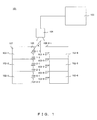
- FIG. 1 is a configuration diagram of a temperature measurement system according to the first embodiment.
- FIG. 2 is an oblique perspective of a rack and a measurement plate according to the first embodiment.
- FIG. 1 is a top view of the temperature measurement system 101, and in FIG. 2 , in order to make it easier to view the racks 102 and the temperature measurement plates 103, a part of the racks 102 and the temperature measurement plates 103 is omitted.
- the rack 102 On the rack 102, information processing apparatuses such as a server and a storage are mounted.
- the rack 102 is a rectangular solid, and has an intake plane 106 on which an intake opening to intake air is provided and an exhaust plane 107 on which an exhaust opening to release air is provided.
- the front plane of the rack 102 is the intake plane 106
- the back plane is the exhaust plane 107.
- the racks 102 are arranged in parallel in two rows with three units each, and are aligned so that the intake planes 106 of the respective rows face each other. In addition, the lateral sides of adjacent racks 102 are in close contact with each other.
- Two temperature measurement plates 103 are attached per rack.
- the temperature measurement plane 103 is attached to an end of the intake plane 106 closer to the infrared camera 104 and in the center.
- the temperature measurement plane 103 is attached perpendicularly to the intake plane 106 and in the top-bottom (longitudinal) direction (the perpendicular direction to the installment plane of the rack 102).
- the length of the temperature measurement plate 103 (the height direction of the rack 102) is the same a the height of the rack 102.
- the thickness of the temperature measurement plate 103 is set as 1 millimeter or below.
- the temperature measurement plate 103 is in the black color that has a low infrared ray reflection rate.
- the temperature measurement plate 103 is made of a material such as paper, cloth, plastic, or metal, and the like.
- the temperature measurement plate 103 Since the temperature measurement plate 103 is attached on the intake plane 106 or the exhaust plane 107, the temperature of the temperature measurement plate 103 becomes almost equal to the intake temperature or the exhaust temperature, and emits infrared ray corresponding to the temperature. Therefore, by measuring the temperature of the temperature measurement plate 103, it becomes possible to know the intake temperature or the exhaust temperature.
- the infrared camera 104 detects infrared ray emitted from an object.
- the infrared camera 104 is installed so as to capture the space between racks 104 aligned in two rows.
- the measurement apparatus 105 analysis data obtained from the infrared camera 104, and performs display, measurement and the like of the temperature data. Meanwhile, the infrared camera 104 may be configured to include functions of the measurement apparatus 105.
- the information processing apparatuses mounted inside the rack 102 are not to be seen from the lateral side, but since the intake plane 106 has the intake opening and the exhaust plane has the exhaust opening, the information processing apparatuses mounted inside the rack 102 are seen from the intake plane 106 or the exhaust plane 107. Therefore, if the information processing apparatuses are seen from the infrared camera 104, the temperature of the information processing apparatus is measured, so the infrared camera is placed so that the intake plane 106 or the exhaust plane 107 are not to be seen from the infrared camera 104 by means of the temperature measurement plate 103.
- the angle between the optical axis of the lens of the infrared camera 104 and the line connecting the center of the lens and the center of the rack 102-1 that is closest to the infrared camera is assumed to be angle A.
- the infrared camera 104 is installed so that the angle A falls between 30 degrees and 90 degrees.
- the width of the temperature measurement plate 103 is half of the width of the rack when two temperature measurement plates are attached per rack and the width of the temperature measurement plate 103 is one third of the width of the rack when three temperature measurement plates are attached per rack, so that the intake plane 106 is not to be seen from the infrared camera.
- the installment position of the infrared camera 104, the width of the temperature measurement plate 103 ,and the number of the temperature measurement plates may be set arbitrarily within the range of conditions in which all the temperature measurement plates 103 can be seen and the intake plane 106 and the exhaust plane 107 can not be seen from the infrared camera 104.
- FIG. 3 is a camera image of the infrared camera according to the first embodiment.
- the intake plane 106 is not captured, and all the temperature measurement plates 103 are captured. Therefore, it becomes possible to measure the intake temperature of the information processing apparatuses mounted on the rack 103 from the camera image.
- FIG. 4 is another configuration diagram of a temperature measurement system according to the first embodiment.
- temperature measurement system 111 In the temperature measurement system 111, three temperature measurement plates 108 are attached per rack.
- the temperature measurement plates 108 are attached to the end of the intake plane 106 on the side that is close to the infrared camera 104, and at the positions corresponding to one third and two thirds of the width of the rack from the end.
- the temperature measurement plate 108 is attached perpendicularly to the intake plane 106 and in the top-bottom (longitudinal) direction of the rack 102.
- the length, thickness, and material of the temperature measurement plate 108 are the same as the temperature measurement plate 103.
- temperature measurement is performed by image capturing of the temperature measurement plates 103, 108 by the infrared camera 104, making it possible to measure the intake temperature or the exhaust temperature easiliy.
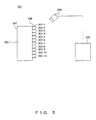
- FIG. 5 is a side view of a temperature measurement system according to the second embodiment.
- FIG. 6 is an oblique perspective of the temperature measurement system according to the second embodiment.
- the functions of the rack 202, the temperature measurement plate 203, the infrared camera 204, and the measurement apparatus 205 according to the second embodiment are the same as those of the rack 102, the temperature measurement plate 103, the infrared camera 104 and the measurement apparatus 105 according to the first embodiment, their description is omitted.
- the temperature measurement plate 203 is attached vertically to an air intake plane 206 and in the horizontal (lateral) direction (the direction parallel to the plane on which rack 202 is placed).
- the length of the temperature measurement plane 203 is equal to the width of the three racks 202.
- the temperature measurement plate 203 is attached at a predetermined interval from the top of the air intake plane 206 in the downward direction. In the second embodiment, 11 temperature measurement plates 203 are attached.
- the infrared camera 204 is placed in the front upper part of the air intake plane 206.
- the infrared camera 024 is placed on the ceiling of the room in which the rack 202 is placed.
- the infrared camera is placed on a position from which all the temperature measurement plates 203 are captured and the air intake plane is not captured.
- FIG. 7 is an infrared camera image according to the second embodiment.
- the air intake plane 206 is not captured, and all the temperature measurement plate 203 is captured. Therefore, it becomes possible to measure the intake temperature of the information processing apparatus mounted on the rack 203 from the camera image.
- the exhaust temperature may be measured by attaching it to the exhaust plane 207.
- FIG. 8 is a side view of a temperature measurement system according to the third embodiment.
- FIG. 9 is an oblique view of a temperature measurement system according to the third embodiment.
- the functions of the rack 302, the temperature measurement plate 303, the infrared camera 304, and the measurement apparatus 305 according to the third embodiment are the same as those of the rack 102, the temperature measurement plate 103, the infrared camera 104 and the measurement apparatus 105 according to the first embodiment, their description is omitted.
- 11 temperature measurement plates 303 are used.
- the width of one temperature measurement plate 303 is supposed to be one eleventh of the height of the rack 302.
- the length of the temperature measurement plate 303 is equal to or longer than width of the three racks 302.
- the temperature measurement plate 303 is placed in parallel to the air intake plane 206 and at a certain distance from the air intake plane 306 and in the horizontal (lateral) direction.
- the temperature measurement plate 303-1 is placed so that the top end position of the temperature measurement plate 303-1 is aligned with the height of the rack 302, and to be away from the air intake plane 306 by a distance 2X.
- the temperature measurement plate 303-2 is placed so that the top end position of the temperature measurement plate 303-2 is aligned with the level of the bottom end of the temperature measurement plate 303-1, and to be away from the air intake plane 306 by a distance X.
- the distance X is set to an appropriate value.
- the distance X is set as equivalent to the width of the temperature measurement plate 303.
- the temperature measurement plates 303 By placing the temperature measurement plates 303 as described above, from the front (air intake) plane, it looks like the temperature measurement plates 303 covers the front plane of the rack 302.
- the infrared camera 304 is placed in front of the rack 302 across the temperature measurement plates 303, and captures the image of the temperature measurement plates 303.
- the infrared camera 304 is placed in front of the rack 302-2 placed in the center among the three racks 302 .
- the infrared camera 304 is placed, for example, at the position of the half of the height of the rack 302.
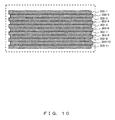
- FIG. 10 is an infrared camera image according to the third embodiment.
- the air intake plane 306 is not captured, and all the temperature measurement plates 303 are captured. Therefore, it becomes possible to measure the intake temperature of the information processing apparatus mounted on the rack 303, from the camera image.
- the exhaust temperature may be measured by attaching it to the exhaust plane 307.
- any number of the temperature measurement plates 303 may be used.
- the temperature measurement system 301 since the temperature measurement is performed by capturing the temperature measurement plates 303 by the infrared camera 304, it becomes possible to measure the intake temperature or the exhaust temperature easily.
Landscapes
- Physics & Mathematics (AREA)
- General Physics & Mathematics (AREA)
- Spectroscopy & Molecular Physics (AREA)
- Engineering & Computer Science (AREA)
- Computer Hardware Design (AREA)
- General Engineering & Computer Science (AREA)
- Thermal Sciences (AREA)
- Microelectronics & Electronic Packaging (AREA)
- Radiation Pyrometers (AREA)
Abstract
A temperature measurement system(101, 201, 301) including a measurement plate (103, 108, 203, 303) placed on a measurement plane specified on at least one of an intake opening and an exhaust opening of a rack storing an information processing apparatus or at a position being away from the measurement plane by a predetermined distance; and an infrared camera (104, 204, 304) configured to capture an image of the measurement plate, where the infrared camera is placed at a position with which the measurement plane is not captured and the measurement plate is captured by the infrared camera.
Description
- The embodiments discussed herein are related to a system and method to measure the intake temperature or the exhaust temperature of an information processing apparatus.
- In a room or space called a data center, a machine room or a server room, Information Technology (IT) devices such as servers, and a rack on which IT devices are stacked and mounted are placed.
- An IT device has functional components such as the Central Processing Unit (CPU), the memory, and the like, and the functional components fulfill their functions while consuming power. Then, heat is generated as a result, but in order to guarantee the operation, or in order to secure the reliability of the operation, the temperature of functional components need to be kept equal to or below a certain temperature. For this reason, IT devices generally have an airflow generation component, for cooling by forced air cooling and the like.
- For a general IT device, on an assumption that air of a temperature equal to or below a certain temperature is taken in from an air intake, the upper limit temperature of the air to be taken is determined as the operation guarantee temperature. In a data center and a machine room, a number of IT devices are placed in a certain space/room, and if no measure is taken, the temperature of the air in the space/room keeps increasing by heat generation by the IT devices.
- Then, in a data center and a machine room in which IT devices are placed, generally, in the same space/roam or in a separately-provided room, space, an air conditioning system that has a function to draw heat from the IT device installation area and to release it outside the area in which the IT devices are placed is provided so that the operation guarantee temperature of the IT devices is not exceeded.
- Therefore, in the air circulation of the space/room, the reasonable form is that the air of a relatively row temperature released from the air conditioning system is provided to the air intake plane of the IT devices/IT device mounting rack, and the airflow generation component such as a fan built in the IT device is driven to take it in, thereby cooling the functional components such as the CPU, and the air of a relatively high temperature that has drawn the heat of the IT device is released from the IT device's outlet. The air promptly returns to the intake of the air conditioning system, and is taken in into the air conditioner, where its heat is drawn and it becomes air of a low temperature, and is blown out of the air conditioner.
- In a general data center, IT devices are placed in the center part of the computer room, and the air conditioner is placed in the peripheral area of the computer room. In some cases, it is placed outside the computer room in which IT devices are placed, and as a result, it may be placed in the surroundings of the IT device installation area. In this case, the air conditioner is in charge of cooling IT devices in a broad area, and performing generally-even cooling.
- However, in a data center, if heat generation density of the IT devices is not even and heat generation is concentrated locally, the airflow required by the IT devices also increases locally, and an air conditioner that provides evenly-cold air can no longer provide the required air volume. When supply of cold air falls short, the exhaust of the IT devices comes around to the intake plane side, making an area where the intake temperature of the IT device is high. The reliability of an IT device generally decreases when its intake temperature becomes high, and its life is also shortened.
- As a method for solving this problem, additional installment of an air conditioner placed in the outer circumference of the computer room would be possible, but it is difficult to deliver the effect to a specific place, and energy will be wasted as the effect extends into a broad area and useless cooling will be performed for the part that does not require additional cooling power.
- As another solution, there is a method in which a local air conditioner is installed in the vicinity of an IT device that has a high heat generation density. Since installment can be made in the vicinity of the area with local heat generation, the efficiency may be improved.
- In data centers in recent years, the intake area and the exhaust area are often separated. By doing so, cold air released from the air conditioner is provided to the intake plane of the IT device, to avoid exhaust of a high temperature from coming around to the IT device intake plane to improve the reliability of the IT device, and the exhaust of the IT device is returned to the air conditioner while keeping it at the high temperature, to improve the efficiency of the air conditioner.
- In the viewpoint of safe operation, it is important to measure and manage the intake temperature and the exhaust temperature of the IT devices in a data center. Especially in a data center, a number of IT devices are aligned and installed and a wide area is managed collectively, the temperature distribution in a wide area needs to be measured efficiently.
- In the conventional intake/exhaust temperature management method, a temperature sensor such as a thermistor and the like that obtains temperature information from an electric signal is placed on the intake plane or the exhaust plane of the rack. With this method, however, there has been a problem that a large number of sensors need to be prepared and installed to capture temperature distribution in a wide area, especially temperature distribution in the wide area in which a plurality of IT devices are aligned and installed, which is troublesome.
- [Patent document 1] Japanese Laid-open Patent Publication No.
H11-6770 - [Patent document 2] Japanese Laid-open Patent Publication No.
2000-323883 - [Patent document 3] Japanese Laid-open Patent Publication No.
2002-118387 - [Patent document 4] Japanese Laid-open Patent Publication No.
H11-83643 - It is an object in one aspect of the invention to provide a system that is capable of measuring temperature easily.
- According to an aspect of the invention, a temperature measurement system includes a measurement plate placed on a measurement plane specified on at least one of an intake opening and an exhaust opening of a rack storing an information processing apparatus or at a position being away from the measurement plane by a predetermined di stance; and an infrared camera configured to capture an image of the measurement plate.
- The infrared camera is placed at a position with which the measurement plane is not captured and the measurement plate is captured by the infrared camera.
-
-
FIG. 1 is a configuration diagram of a temperature measurement system according to the first embodiment. -
FIG. 2 is an oblique perspective of a rack and a temperature measurement plate according to the first embodiment. -
FIG. 3 is a camera image of an infrared camera according to the first embodiment. -
FIG. 4 is another configuration diagram of a temperature measurement system according to the first embodiment. -
FIG. 5 is a side view of a temperature measurement system according to the second embodiment. -
FIG. 6 is an oblique perspective of the temperature measurement system according to the second embodiment. -
FIG. 7 is a camera image of an infrared camera according to the second embodiment. -
FIG. 8 is a side view of a temperature measurement system according to the third embodiment. -
FIG. 9 is an oblique perspective of the temperature measurement system according to the third embodiment. -
FIG. 10 is a camera image of an infrared camera according to the third embodiment. - Hereinafter, embodiments are described with reference to the drawings.
-
FIG. 1 is a configuration diagram of a temperature measurement system according to the first embodiment. -
FIG. 2 is an oblique perspective of a rack and a measurement plate according to the first embodiment. - A
temperature measurement system 101 according to the first embodiment has a plurality of racks 102-n (n=1-6), a plurality of temperature measurement plates 103-n-m (m=1-2), aninfrared camera 104, and ameasurement apparatus 105. - Meanwhile,
FIG. 1 is a top view of thetemperature measurement system 101, and inFIG. 2 , in order to make it easier to view the racks 102 and the temperature measurement plates 103, a part of the racks 102 and the temperature measurement plates 103 is omitted. - On the rack 102, information processing apparatuses such as a server and a storage are mounted. The rack 102 is a rectangular solid, and has an
intake plane 106 on which an intake opening to intake air is provided and anexhaust plane 107 on which an exhaust opening to release air is provided. In the first embodiment, the front plane of the rack 102 is theintake plane 106, and the back plane is theexhaust plane 107. - The racks 102 are arranged in parallel in two rows with three units each, and are aligned so that the
intake planes 106 of the respective rows face each other. In addition, the lateral sides of adjacent racks 102 are in close contact with each other. - Two temperature measurement plates 103 are attached per rack.
- The temperature measurement plane 103 is attached to an end of the
intake plane 106 closer to theinfrared camera 104 and in the center. The temperature measurement plane 103 is attached perpendicularly to theintake plane 106 and in the top-bottom (longitudinal) direction (the perpendicular direction to the installment plane of the rack 102). - The length of the temperature measurement plate 103 (the height direction of the rack 102) is the same a the height of the rack 102.
- The thickness of the temperature measurement plate 103 is set as 1 millimeter or below.
- It is desirable that, in order to reduce the influence from the reflection of the infrared ray, the temperature measurement plate 103 is in the black color that has a low infrared ray reflection rate. In addition, the temperature measurement plate 103 is made of a material such as paper, cloth, plastic, or metal, and the like.
- Since the temperature measurement plate 103 is attached on the
intake plane 106 or theexhaust plane 107, the temperature of the temperature measurement plate 103 becomes almost equal to the intake temperature or the exhaust temperature, and emits infrared ray corresponding to the temperature. Therefore, by measuring the temperature of the temperature measurement plate 103, it becomes possible to know the intake temperature or the exhaust temperature. - The
infrared camera 104 detects infrared ray emitted from an object. - The
infrared camera 104 is installed so as to capture the space betweenracks 104 aligned in two rows. - The
measurement apparatus 105 analysis data obtained from theinfrared camera 104, and performs display, measurement and the like of the temperature data. Meanwhile, theinfrared camera 104 may be configured to include functions of themeasurement apparatus 105. - Since the lateral side of the rack 102 has an opaque side wall, the information processing apparatuses mounted inside the rack 102 are not to be seen from the lateral side, but since the
intake plane 106 has the intake opening and the exhaust plane has the exhaust opening, the information processing apparatuses mounted inside the rack 102 are seen from theintake plane 106 or theexhaust plane 107. Therefore, if the information processing apparatuses are seen from theinfrared camera 104, the temperature of the information processing apparatus is measured, so the infrared camera is placed so that theintake plane 106 or theexhaust plane 107 are not to be seen from theinfrared camera 104 by means of the temperature measurement plate 103. - Looking at
temperature measurement system 101 from above, the angle between the optical axis of the lens of theinfrared camera 104 and the line connecting the center of the lens and the center of the rack 102-1 that is closest to the infrared camera is assumed to be angle A. - In the first embodiment, the
infrared camera 104 is installed so that the angle A falls between 30 degrees and 90 degrees. - For example, it is preferable that, when the infrared camera is installed so that the angle A becomes 45 degrees, the width of the temperature measurement plate 103 is half of the width of the rack when two temperature measurement plates are attached per rack and the width of the temperature measurement plate 103 is one third of the width of the rack when three temperature measurement plates are attached per rack, so that the
intake plane 106 is not to be seen from the infrared camera. - Meanwhile, the installment position of the
infrared camera 104, the width of the temperature measurement plate 103 ,and the number of the temperature measurement plates may be set arbitrarily within the range of conditions in which all the temperature measurement plates 103 can be seen and theintake plane 106 and theexhaust plane 107 can not be seen from theinfrared camera 104. -
FIG. 3 is a camera image of the infrared camera according to the first embodiment. - In the camera image in
FIG. 3 , theintake plane 106 is not captured, and all the temperature measurement plates 103 are captured. Therefore, it becomes possible to measure the intake temperature of the information processing apparatuses mounted on the rack 103 from the camera image. -
FIG. 4 is another configuration diagram of a temperature measurement system according to the first embodiment. - The
temperature measurement system 111 according to the first embodiment has a plurality of racks 102-n (n=1-6), a plurality of temperature measurement plates 108-n-k(k=1-3), aninfrared camera 104 and ameasurement apparatus 105. - Since the racks 102, the
infrared camera 104 and themeasurement apparatus 105 are the same as those described above, description of them is omitted. - In the
temperature measurement system 111, three temperature measurement plates 108 are attached per rack. - The temperature measurement plates 108 are attached to the end of the
intake plane 106 on the side that is close to theinfrared camera 104, and at the positions corresponding to one third and two thirds of the width of the rack from the end. The temperature measurement plate 108 is attached perpendicularly to theintake plane 106 and in the top-bottom (longitudinal) direction of the rack 102. - The length, thickness, and material of the temperature measurement plate 108 are the same as the temperature measurement plate 103.
- According to the
temperature measurement system 101 according to the first embodiment, temperature measurement is performed by image capturing of the temperature measurement plates 103, 108 by theinfrared camera 104, making it possible to measure the intake temperature or the exhaust temperature easiliy. -
FIG. 5 is a side view of a temperature measurement system according to the second embodiment. -
FIG. 6 is an oblique perspective of the temperature measurement system according to the second embodiment. - A
temperature measurement system 201 according to the second embodiment has a plurality of racks 202-p (p=1-3), a plurality of temperature measurement plates 203-q (q=1-11), aninfrared camera 204, and ameasurement apparatus 205. - Since the functions of the rack 202, the temperature measurement plate 203, the
infrared camera 204, and themeasurement apparatus 205 according to the second embodiment are the same as those of the rack 102, the temperature measurement plate 103, theinfrared camera 104 and themeasurement apparatus 105 according to the first embodiment, their description is omitted. - In the second embodiment, three racks 202 are placed next to each other.
- The temperature measurement plate 203 is attached vertically to an
air intake plane 206 and in the horizontal (lateral) direction (the direction parallel to the plane on which rack 202 is placed). - The length of the temperature measurement plane 203 is equal to the width of the three racks 202.
- The temperature measurement plate 203 is attached at a predetermined interval from the top of the
air intake plane 206 in the downward direction. In the second embodiment, 11 temperature measurement plates 203 are attached. - The
infrared camera 204 is placed in the front upper part of theair intake plane 206. For example, the infrared camera 024 is placed on the ceiling of the room in which the rack 202 is placed. Specifically, the infrared camera is placed on a position from which all the temperature measurement plates 203 are captured and the air intake plane is not captured. -
FIG. 7 is an infrared camera image according to the second embodiment. - In the camera image in
FIG. 7 , theair intake plane 206 is not captured, and all the temperature measurement plate 203 is captured. Therefore, it becomes possible to measure the intake temperature of the information processing apparatus mounted on the rack 203 from the camera image. - Meanwhile, while the intake temperature is measured by attaching the temperature measurement plate 203 to the
air intake plane 206 in the second embodiment, the exhaust temperature may be measured by attaching it to theexhaust plane 207. -
FIG. 8 is a side view of a temperature measurement system according to the third embodiment. -
FIG. 9 is an oblique view of a temperature measurement system according to the third embodiment. - A
temperature measurement system 301 according to the third embodiment has a plurality of racks 302-p (p=1-3), a plurality of temperature measurement plates 303-qEq=1--11), aninfrared camera 304, and ameasurement apparatus 305. - Since the functions of the rack 302, the temperature measurement plate 303, the
infrared camera 304, and themeasurement apparatus 305 according to the third embodiment are the same as those of the rack 102, the temperature measurement plate 103, theinfrared camera 104 and themeasurement apparatus 105 according to the first embodiment, their description is omitted. - In the third embodiment, three racks 302 are placed next to each other.
- In the third embodiment, 11 temperature measurement plates 303 are used. The width of one temperature measurement plate 303 is supposed to be one eleventh of the height of the rack 302. The length of the temperature measurement plate 303 is equal to or longer than width of the three racks 302.
- The temperature measurement plate 303 is placed in parallel to the
air intake plane 206 and at a certain distance from theair intake plane 306 and in the horizontal (lateral) direction. - Specifically, the temperature measurement plate 303-1 is placed so that the top end position of the temperature measurement plate 303-1 is aligned with the height of the rack 302, and to be away from the
air intake plane 306 by a distance 2X. - The temperature measurement plate 303-2 is placed so that the top end position of the temperature measurement plate 303-2 is aligned with the level of the bottom end of the temperature measurement plate 303-1, and to be away from the
air intake plane 306 by a distance X. - Thereafter, by placing the temperature measurement plate 303 in the same manner, the temperature measurement plates 303- (2r+1) (r=0-5) are placed to be away from the
air intake plane 306 by the distance 2X and the temperature measurement plate 303-2r is placed to be away from theair intake plane 206 by the distance X. - By placing the temperature measurement plates 303 at different distances alternately, air can be taken from the space between the temperature measurement plates 303, making it possible to reduce impact on the air intake.
- As for the distance X between the
air intake plane 306 and the temperature measurement plate 303, if the distance X is too small, it affects the air intake negatively, and if the distance X is too large, the difference between the intake temperature and the temperature of the temperature measurement plate 303 increases, making it impossible tomeasure the intake temperature accurately, so the distance X is set to an appropriate value. For example, in the third embodiment, the distance X is set as equivalent to the width of the temperature measurement plate 303. - By placing the temperature measurement plates 303 as described above, from the front (air intake) plane, it looks like the temperature measurement plates 303 covers the front plane of the rack 302.
- The
infrared camera 304 is placed in front of the rack 302 across the temperature measurement plates 303, and captures the image of the temperature measurement plates 303. Theinfrared camera 304 is placed in front of the rack 302-2 placed in the center among the three racks 302 . In addition, theinfrared camera 304 is placed, for example, at the position of the half of the height of the rack 302. -
FIG. 10 is an infrared camera image according to the third embodiment. - In the camera image in
FIG. 10 , theair intake plane 306 is not captured, and all the temperature measurement plates 303 are captured. Therefore, it becomes possible to measure the intake temperature of the information processing apparatus mounted on the rack 303, from the camera image. - Meanwhile, while the intake temperature is measured by attaching the temperature measurement plate 303 to the
air intake plane 306 in the second embodiment, the exhaust temperature may be measured by attaching it to theexhaust plane 307. - In addition, any number of the temperature measurement plates 303 may be used.
- According to the
temperature measurement system 301 according to the third embodiment, since the temperature measurement is performed by capturing the temperature measurement plates 303 by theinfrared camera 304, it becomes possible to measure the intake temperature or the exhaust temperature easily. - All examples and conditional language recited herein are intended for pedagogical purposes to aid the reader in understanding the invention and the concepts contributed by the inventor to furthering the art, and are to be construed as being without limitation to such specifically recited examples and conditions, nor does the organization of such examples in the specification relate to a showing of the superiority and inferiority of the invention. Although the embodiment (s) of the present invention has (have) been described in detail, it should be understood that the various changes, substitutions, and alterations could be made hereto without departing from the spirit and scope of the invention.
Claims (10)
- A temperature measurement system (101, 201, 301) comprising:a measurement plate (103, 108, 203, 303) placed on a measurement plane specified on at least one of an intake opening and an exhaust opening of a rack storing an information processing apparatus or at a position being away from the measurement plane by a predetermined distance; andan infrared camera (104, 204, 304) configured to capture an image of the measurement plate, whereinthe infrared camera is placed at a position with which the measurement plane is not captured and the measurement plate is captured by the infrared camera.
- The temperature measurement system according to claim 1, wherein
the measurement plate is placed vertically to the measurement plane and in a vertical direction to a plane on which the rack is placed. - The temperature measurement system according to claim 2, wherein
a length of the measurement plate in a height direction of the rack is equal to a height of the rack. - The temperature measurement system according to claim 1, wherein
the measurement plate is placed in a direction that is vertical to the measurement plane and is parallel to a plane on which the rack is placed. - The temperature measurement system according to claim 1, wherein
the measurement plate is placed in parallel to the measurement plane. - A temperature measurement method comprising:placing a measurement plate on a measurement plane specified on at least one of an intake opening and an exhaust opening of a rack storing an information processing apparatus or at a position being away from the measurement plane by a predetermined distance;placing an infrared camera at a position with which the measurement plane is not captured and the measurement plate is captured by the infrared camera; andcapturing an image of the measurement plate by the infrared camera.
- The temperature measurement method according to claim 6, wherein
the measurement plate is placed vertically to the measurement plane and in a vertical direction to a plane on which the rack is placed. - The temperature measurement method according to claim 7, wherein
a length of the measurement plate in a height direction of the rack is equal to a height of the rack. - The temperature measurement method according to claim 6, wherein
the measurement plate is placed in a direction that is vertical to the measurement plane and is parallel to a plane on which the rack is placed. - The temperature measurement method according to claim 6, wherein
the measurement plate is placed in parallel to the measurement plane.
Applications Claiming Priority (1)
| Application Number | Priority Date | Filing Date | Title |
|---|---|---|---|
| JP2011034996A JP2012173118A (en) | 2011-02-21 | 2011-02-21 | Temperature measurement system and temperature measuring method |
Publications (1)
| Publication Number | Publication Date |
|---|---|
| EP2489999A1 true EP2489999A1 (en) | 2012-08-22 |
Family
ID=45443046
Family Applications (1)
| Application Number | Title | Priority Date | Filing Date |
|---|---|---|---|
| EP12150747A Withdrawn EP2489999A1 (en) | 2011-02-21 | 2012-01-11 | Temperature measurement system and temperature measurement method |
Country Status (4)
| Country | Link |
|---|---|
| US (1) | US8342746B2 (en) |
| EP (1) | EP2489999A1 (en) |
| JP (1) | JP2012173118A (en) |
| CN (1) | CN102645283A (en) |
Cited By (2)
| Publication number | Priority date | Publication date | Assignee | Title |
|---|---|---|---|---|
| CN110057464A (en) * | 2019-04-30 | 2019-07-26 | 西安航空制动科技有限公司 | A kind of temperature measuring equipment of vacuum drying oven |
| EP3862733A1 (en) * | 2020-02-05 | 2021-08-11 | Siemens Gamesa Renewable Energy A/S | Temperature measurement assembly |
Families Citing this family (7)
| Publication number | Priority date | Publication date | Assignee | Title |
|---|---|---|---|---|
| CN104111122A (en) * | 2013-04-22 | 2014-10-22 | 成都勤智数码科技股份有限公司 | Machine room environment data fine-collection system |
| JP6425452B2 (en) * | 2014-08-18 | 2018-11-21 | 日立ジョンソンコントロールズ空調株式会社 | AIR CONDITIONER AND CONTROL METHOD OF AIR CONDITIONER |
| JP6698288B2 (en) * | 2015-07-28 | 2020-05-27 | 日鉄エンジニアリング株式会社 | Device for identifying temperature distribution in server rack room and method for identifying temperature distribution |
| CN105716198A (en) * | 2016-02-04 | 2016-06-29 | 四川长虹电器股份有限公司 | Air conditioner control device and control method thereof |
| CN109196516B (en) * | 2016-06-03 | 2022-04-19 | 三菱电机株式会社 | Device control apparatus and device control method |
| JP7033516B2 (en) * | 2018-08-28 | 2022-03-10 | エヌ・ティ・ティ・コミュニケーションズ株式会社 | Air conditioning setting selection system for data centers |
| JP7718841B2 (en) * | 2021-03-31 | 2025-08-05 | 高砂熱学工業株式会社 | Temperature distribution measurement method, air conditioning control system, server room, and thermal distribution imaging device |
Citations (6)
| Publication number | Priority date | Publication date | Assignee | Title |
|---|---|---|---|---|
| JPH116770A (en) | 1997-04-25 | 1999-01-12 | Ricoh Co Ltd | Apparatus and method for measuring temperature in temperature field |
| JPH1183643A (en) | 1997-09-03 | 1999-03-26 | Ricoh Co Ltd | Method and apparatus for measuring heat flow direction and temperature |
| JP2000323883A (en) | 1999-05-14 | 2000-11-24 | Nec Corp | Cooling device |
| JP2002118387A (en) | 2000-10-05 | 2002-04-19 | Toshiba Corp | Electronic computer cooling structure |
| US20090017816A1 (en) * | 2007-07-11 | 2009-01-15 | Timothy Joseph Chainer | Identification of equipment location in data center |
| US20090238235A1 (en) * | 2008-03-24 | 2009-09-24 | International Business Machines Corporation | Method and apparatus for defect detection in a cold plate |
Family Cites Families (17)
| Publication number | Priority date | Publication date | Assignee | Title |
|---|---|---|---|---|
| JPS5552919A (en) * | 1978-10-16 | 1980-04-17 | Natl Aerospace Lab | Method and device for metering temperature distribution of flow gas |
| JPS56143931A (en) * | 1980-04-10 | 1981-11-10 | Asahi Chem Ind Co Ltd | Method for measurement of temperature distribution of spacial part in room of building |
| JPS61181921A (en) * | 1985-02-07 | 1986-08-14 | Mitsubishi Heavy Ind Ltd | Gas temperature measurement |
| JPS61186825A (en) * | 1985-02-14 | 1986-08-20 | Jeol Ltd | Measuring method of temperature distribution using thermography device |
| JPS63100339A (en) * | 1986-06-20 | 1988-05-02 | Nkk Corp | Temperature distribution measurement method and temperature detection plate |
| JPH01176922A (en) * | 1988-01-06 | 1989-07-13 | Toshiba Corp | Exhaust gas temperature detecting device for gas turbine |
| JPH03115820A (en) * | 1989-09-28 | 1991-05-16 | Mazda Motor Corp | Method for measuring air temperature |
| JPH0815042A (en) * | 1994-06-28 | 1996-01-19 | Toshiba Corp | Gas turbine working gas temperature measuring device |
| JP3417779B2 (en) * | 1997-01-27 | 2003-06-16 | 三菱電機株式会社 | Print card temperature measuring device |
| JP2001124628A (en) * | 1999-10-28 | 2001-05-11 | Sekisui Chem Co Ltd | Temperature distribution measurement device, indoor temperature distribution measurement method, indoor temperature distribution visualization device, and building design method |
| DE102007005618A1 (en) * | 2007-01-31 | 2008-08-07 | Institut für Automation und Kommunikation (ifak) e. V. Magdeburg | Device and method for determining the amount of substance in small cavities |
| JP5038234B2 (en) * | 2008-05-26 | 2012-10-03 | 株式会社グローバルエンジニアリング | Server computer temperature monitoring method and apparatus |
| JP2010019624A (en) * | 2008-07-09 | 2010-01-28 | Tokyo Electric Power Co Inc:The | Gas temperature distribution detection system and detector |
| JP5176840B2 (en) * | 2008-09-30 | 2013-04-03 | 株式会社日立プラントテクノロジー | Air conditioning control system and air conditioning control method |
| JP5488978B2 (en) * | 2010-02-03 | 2014-05-14 | 東京電力株式会社 | Spatial temperature distribution measuring device and measuring method |
| JP5621413B2 (en) * | 2010-08-25 | 2014-11-12 | 富士通株式会社 | Cooling system and cooling method |
| JP5729993B2 (en) * | 2010-12-08 | 2015-06-03 | 高砂熱学工業株式会社 | Imaging target apparatus and temperature distribution measuring method |
-
2011
- 2011-02-21 JP JP2011034996A patent/JP2012173118A/en active Pending
-
2012
- 2012-01-11 EP EP12150747A patent/EP2489999A1/en not_active Withdrawn
- 2012-01-13 US US13/349,735 patent/US8342746B2/en not_active Expired - Fee Related
- 2012-01-29 CN CN2012100202663A patent/CN102645283A/en active Pending
Patent Citations (6)
| Publication number | Priority date | Publication date | Assignee | Title |
|---|---|---|---|---|
| JPH116770A (en) | 1997-04-25 | 1999-01-12 | Ricoh Co Ltd | Apparatus and method for measuring temperature in temperature field |
| JPH1183643A (en) | 1997-09-03 | 1999-03-26 | Ricoh Co Ltd | Method and apparatus for measuring heat flow direction and temperature |
| JP2000323883A (en) | 1999-05-14 | 2000-11-24 | Nec Corp | Cooling device |
| JP2002118387A (en) | 2000-10-05 | 2002-04-19 | Toshiba Corp | Electronic computer cooling structure |
| US20090017816A1 (en) * | 2007-07-11 | 2009-01-15 | Timothy Joseph Chainer | Identification of equipment location in data center |
| US20090238235A1 (en) * | 2008-03-24 | 2009-09-24 | International Business Machines Corporation | Method and apparatus for defect detection in a cold plate |
Cited By (2)
| Publication number | Priority date | Publication date | Assignee | Title |
|---|---|---|---|---|
| CN110057464A (en) * | 2019-04-30 | 2019-07-26 | 西安航空制动科技有限公司 | A kind of temperature measuring equipment of vacuum drying oven |
| EP3862733A1 (en) * | 2020-02-05 | 2021-08-11 | Siemens Gamesa Renewable Energy A/S | Temperature measurement assembly |
Also Published As
| Publication number | Publication date |
|---|---|
| US8342746B2 (en) | 2013-01-01 |
| CN102645283A (en) | 2012-08-22 |
| JP2012173118A (en) | 2012-09-10 |
| US20120213247A1 (en) | 2012-08-23 |
Similar Documents
| Publication | Publication Date | Title |
|---|---|---|
| US8342746B2 (en) | Temperature measurement system and temperature measurement method | |
| US10356954B2 (en) | Cabinet structure and container data center thereof | |
| US8089754B2 (en) | Computer server system and server thereof | |
| US7366632B2 (en) | Method and apparatus for three-dimensional measurements | |
| US20120006507A1 (en) | Multi-modular data center | |
| US8407004B2 (en) | Airflow detector and method of measuring airflow | |
| US20200173670A1 (en) | Air-conditioning device | |
| US10575445B2 (en) | Monitoring apparatus, monitoring method, and program | |
| US9219850B2 (en) | Monitoring camera | |
| CN105466599A (en) | Server cabinet temperature monitoring device and monitoring method | |
| US11778787B2 (en) | System and method for thermal management in a computing environment | |
| JP2018173864A (en) | Information processing system, information processing method, and program | |
| CN205345353U (en) | Parallelly connected cloud platform that carries on miniature thermal infrared imager and moving camera | |
| JPH10206241A (en) | Print card temperature measurement device and wind speed measurement device | |
| US9179573B1 (en) | Rack-mounted multiple server module | |
| CN204717997U (en) | For temperature measurement component and the air-conditioner outdoor unit of air-conditioner outdoor unit | |
| KR20160073187A (en) | Apparatus and method for controlling temperature of data centers | |
| CN108804293A (en) | A kind of server and its contactless storage device temperature monitoring device | |
| CN110941288B (en) | An automatic obstacle avoidance device and method for low-altitude aircraft | |
| CN212137831U (en) | Computer laboratory monitor terminal | |
| CN222621098U (en) | A multi-lens camera | |
| CN216083708U (en) | Excavator square measurement device based on RFID | |
| US20130240196A1 (en) | Container with cooling system | |
| Alissa et al. | Empirical analysis of blower cooling failure in containment: Effects on IT performance | |
| CN216559273U (en) | Checking and weight measuring integrated machine |
Legal Events
| Date | Code | Title | Description |
|---|---|---|---|
| PUAI | Public reference made under article 153(3) epc to a published international application that has entered the european phase |
Free format text: ORIGINAL CODE: 0009012 |
|
| AK | Designated contracting states |
Kind code of ref document: A1 Designated state(s): AL AT BE BG CH CY CZ DE DK EE ES FI FR GB GR HR HU IE IS IT LI LT LU LV MC MK MT NL NO PL PT RO RS SE SI SK SM TR |
|
| AX | Request for extension of the european patent |
Extension state: BA ME |
|
| 17P | Request for examination filed |
Effective date: 20121112 |
|
| STAA | Information on the status of an ep patent application or granted ep patent |
Free format text: STATUS: THE APPLICATION HAS BEEN WITHDRAWN |
|
| 18W | Application withdrawn |
Effective date: 20140603 |