EP2489977B1 - Verfahren zur Bestimmung der 3-D-Koordinaten eines Objekts und zum Kalibrieren eines Industrieroboters - Google Patents
Verfahren zur Bestimmung der 3-D-Koordinaten eines Objekts und zum Kalibrieren eines Industrieroboters Download PDFInfo
- Publication number
- EP2489977B1 EP2489977B1 EP12000475.9A EP12000475A EP2489977B1 EP 2489977 B1 EP2489977 B1 EP 2489977B1 EP 12000475 A EP12000475 A EP 12000475A EP 2489977 B1 EP2489977 B1 EP 2489977B1
- Authority
- EP
- European Patent Office
- Prior art keywords
- camera
- reference marks
- measurement system
- industrial robot
- coordinates
- Prior art date
- Legal status (The legal status is an assumption and is not a legal conclusion. Google has not performed a legal analysis and makes no representation as to the accuracy of the status listed.)
- Active
Links
Images
Classifications
-
- G—PHYSICS
- G01—MEASURING; TESTING
- G01B—MEASURING LENGTH, THICKNESS OR SIMILAR LINEAR DIMENSIONS; MEASURING ANGLES; MEASURING AREAS; MEASURING IRREGULARITIES OF SURFACES OR CONTOURS
- G01B11/00—Measuring arrangements characterised by the use of optical techniques
- G01B11/24—Measuring arrangements characterised by the use of optical techniques for measuring contours or curvatures
- G01B11/25—Measuring arrangements characterised by the use of optical techniques for measuring contours or curvatures by projecting a pattern, e.g. one or more lines, moiré fringes on the object
-
- G—PHYSICS
- G01—MEASURING; TESTING
- G01B—MEASURING LENGTH, THICKNESS OR SIMILAR LINEAR DIMENSIONS; MEASURING ANGLES; MEASURING AREAS; MEASURING IRREGULARITIES OF SURFACES OR CONTOURS
- G01B21/00—Measuring arrangements or details thereof, where the measuring technique is not covered by the other groups of this subclass, unspecified or not relevant
- G01B21/02—Measuring arrangements or details thereof, where the measuring technique is not covered by the other groups of this subclass, unspecified or not relevant for measuring length, width, or thickness
- G01B21/04—Measuring arrangements or details thereof, where the measuring technique is not covered by the other groups of this subclass, unspecified or not relevant for measuring length, width, or thickness by measuring coordinates of points
- G01B21/042—Calibration or calibration artifacts
Definitions
- the invention relates to a method according to the definition of claim 1, for determining the 3-D coordinates of an object and for calibrating an industrial robot.
- the object is recorded with a fringe projection system.
- the fringe projection system comprises a projector for projecting a fringe pattern onto the object and a camera for capturing the fringe pattern reflected back from the object.
- the recording is evaluated by an evaluation system, which includes a computer, in particular a PC.
- measuring marks are used, which are mounted on the object and / or on one or more surrounding the object scenes.
- the measuring marks are first measured. This is preferably done by the method of photogrammetry.
- the various shots of the object can be transformed to the measured points, so that a global registration is possible.
- a method is known in which a stripe pattern is projected onto the object by a projector to determine the 3D coordinates of an object.
- the striped pattern reflected by the object is picked up by a camera comprising an optics and a surface sensor, in particular a CCD sensor or CMOS sensor.
- the projector and the camera form a fringe projection system.
- a plurality of reference scenes are arranged, each having a plurality of reference marks. The reference scenes will first be measured. Subsequently, the 3D coordinates of the object are determined by the fringe projection system.
- the object whose 3D coordinates are to be determined is no longer or no longer sufficiently accessible. Due to the reference scenes, the movement paths of the robot can be restricted. Furthermore, parts of the object can be obscured by the reference scenes. Also, the loading of the area surrounded by the reference scenes with new objects to be determined can be difficult.
- a method for determining the 3D coordinates of the surface of an object that can be performed by means of a 3D optical measuring device is known.
- the position of the 3D measuring device is determined by a tracking system.
- An object of the invention is to propose an improved method for determining the 3D coordinates of an object.
- the apparatus which is operated in this method and is not claimed as such comprises a projector for projecting a pattern on the object, a camera connected to the projector for taking the object and one with the projector and the camera-connected reference camera for taking one or more Reference marks of a field of reference marks.
- the pattern projected by the projector is a striped pattern.
- Particularly suitable is a white-light fringe projection.
- the camera preferably comprises an area sensor, in particular a CCD sensor, a CMOS sensor or other area sensor. It is advantageous if the camera comprises an optical system.
- the camera can be directly or indirectly connected to the projector.
- the reference camera is directly or indirectly connected to the projector and the camera. Their position and orientation is fixed in relation to the projector and the camera.
- the projector, the camera and the reference camera form a measuring system for determining the 3D coordinates of the object.
- the device comprises one or more further reference cameras.
- the one or more other reference cameras are fixed in their position and orientation relative to the projector, the camera and the first reference camera. They may be directly or indirectly connected to the projector and / or the camera and / or the reference camera. It is advantageous if the direction of the optical axis of the further reference camera or the further reference cameras is different from the direction of the optical axis of the camera and / or the (first) reference camera and / or the further reference cameras. In general, the more accuracy is achieved, the more reference cameras are used and / or the more different their optical axes and thus viewing directions are distributed. In certain cases, it may be advantageous if the optical axes of the reference cameras are perpendicular to each other. For example, there may be three reference cameras whose optical axes are perpendicular to each other. However, other embodiments are possible.
- the reference cameras may be provided on a camera module. They can be detachably or permanently attached to the camera module.
- the device further comprises an evaluation device for determining the position and / or orientation of the projector and / or the camera and / or the one or more reference cameras.
- the evaluation device can be formed by a computer, in particular a PC. The determination of the position or layers and / or the orientation or orientations can take place by way of the bundle block adjustment.
- the device for determining the 3D coordinates of an object also comprises an industrial robot for positioning this device.
- the device also includes a field of reference marks.
- the reference marks may be attached to one or more walls. However, it is also possible to apply the reference marks in other ways.
- the walls to which the reference marks are attached can form a measuring cell for the object.
- the measuring cell can be closed or open.
- the object of the invention is achieved in that the object is positioned in front of a field of reference marks, the object is completely or partially taken with the device and one or more reference marks of a field of reference marks one or more reference cameras is recorded.
- the field of reference marks is measured photogrammetrically at least once.
- a calibration of the industrial robot This is preferably a multi-axis industrial robot.
- Another object of the invention is to propose an improved method for calibrating an industrial robot.
- a device for determining the 3D coordinates of an object by the industrial robot is positioned in a plurality of predetermined positions. These positions can be predetermined according to their position and / or orientation. In these positions, one or more or all reference marks of a field of reference marks are picked up by the device. From these recordings, the positions of the industrial robot are determined. The positions of the industrial robot can be determined according to their position and / or orientation. The predetermined and determined positions of the industrial robot may be the positions of the outermost arm of the industrial robot. The positions of the industrial robot determined from the photographs are compared with the predetermined positions of the industrial robot.
- This comparison provides a measure of the deviations of the actual positions of the industrial robot from the predetermined positions. This dimension can be taken into account as a correction value for future positions of the industrial robot. It is also possible to form a correction matrix from a plurality of correction values for different predefined positions, which also provides correction values for positions lying therebetween, for example due to interpolation. The interpolation can be performed with various suitable functions.
- This method makes it possible to use only the position of the robot for global registration of the respective recording. This is particularly advantageous when it is not possible that the one or more reference cameras can accommodate a sufficient number of reference marks. This may be the case in particular if the 3D coordinates in the interior of an object, for example a body, are to be determined.
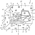
- the measurement setup shown in the drawing serves to determine the 3D coordinates of the front of an object 1, namely a motor vehicle door (shell door).
- the object 1 is positioned in front of a rear wall 2 of a measuring cell 3.
- the measuring cell 3 comprises the rear wall 2, the left side wall 4 and the bottom wall 5.
- the measuring cell 3 further comprises a right side wall, a rear wall and a ceiling wall (not shown in the drawing).
- reference marks 6 On the walls of the measuring cell 3 reference marks 6 are arranged, which are encoded in itself, and reference marks 24, which are not encoded in itself, but which are arranged spatially relative to each other, that this spatial arrangement includes a coding.
- the reference marks 6, 24 form a field 25 of reference marks.
- Each self-coded reference mark 6 comprises a fixed non-coding element and a variable coding element.
- the non-coding element is formed by a circle 7 which is located in the middle of the coded reference mark 6.
- the coding element is formed by segment sections 8. Contrary to the representation in the drawing, the coding element 8 is different for each coded reference mark 6. Due to the different coding elements 8 a unique identification of each coded reference mark 6 is possible.
- a strip projection system 9 is arranged.
- the stiffener projection system 9 comprises a projector 10 and a camera 11.
- the projector 10 projects a pattern, in particular a striped pattern, onto the object 1, as indicated by the arrow 12.
- the camera 11 picks up the stripe pattern reflected by the object 1 in accordance with its spatial surface, as indicated by the arrow 13.
- the projector 10 and the camera 11 are interconnected by a linkage 14. They are fixed in their position and orientation to each other.
- a camera module 15 is connected to the fringe projection system 9.
- the camera module 15 comprises a first reference camera 16, a second reference camera 17 and a third reference camera 18.
- the optical axis 19 and thus the viewing direction of the first reference camera 16 is directed to the rear wall of the measuring cell 3
- the optical axis 20 and thus the viewing direction of the second Reference camera 17 is directed to the right side wall of the measuring cell 3
- the optical axis 21 and thus the viewing direction of the third reference camera 18 is directed to the top wall of the measuring cell 3.
- the right side wall, the rear wall and the top wall of the measuring cell are also provided with reference marks 6, 24.
- the camera module 15 is fixed in its position and orientation relative to the fringe projection system 9. It is connected via a linkage 22 to the linkage 14 of the strip projection system 9.
- the fringe projection system 9 and the camera module 15 form a measuring system 23.
- a first measurement run the positions of the reference marks 6, 24 of the measuring cell 3 are detected and stored.
- no object 1 is located in the measuring cell 3.
- the determination of the positions of the reference marks 6, 24 takes place by way of photogrammetry.
- recordings of the reference marks 6, 24 are produced from different camera positions. This can be done by the camera 11.
- the 3D coordinates of objects can be determined.
- the object 1 is positioned as shown in the drawing in the measuring cell 3.
- the projector 10 projects Strip pattern on the surface of the object 1, the camera 11 receives the reflected fringe pattern and one or more or all of the reference cameras 16, 17, 18 receive reference marks 6, 24 of the field 25 of reference marks.
- each reference camera When using only one reference camera, it is generally necessary to capture at least three coding reference marks 6 when recording. When using three reference cameras, it is generally required that each reference camera detect at least one coding reference mark 6.
- an evaluation device in particular in a computer, in particular in a PC (not shown in the drawing) is from the recordings or the reference marks 6, 24, which have been made by the reference or the reference cameras 16, 17, 18, the position and Orientation of the measuring system 23 determined. This makes it possible to determine from the images of the camera 11, the 3D coordinates of the object 1.
- the object 1 is larger than the field of view of the camera 11, several shots must be taken of the subject 1. These shots may partially overlap one another. Due to the recordings of the reference marks 6, 24 by one or more reference cameras 16, 17, 18, it is possible for each individual photograph of a part of the object 1 by the camera 11, the 3D coordinates of the associated sub-surface of the object 1 as absolute coordinates determine.
- the device further comprises an evaluation device for determining the position and orientation of the measuring system 23, so the projector 10, the camera 11 and the reference cameras 16, 17, 18.
- This evaluation device can be formed by a computer, in particular a PC (in the drawing not shown).
- the measuring system 23 is inventively positioned by an industrial robot (not shown in the drawing).
- the invention provides a method for the global registration of an object.
- a measuring cell in which a robot system can operate is equipped with reference marks.
- the field of reference marks is measured once photogrammetrically.
- the individual measurement recordings for determining the 3D coordinates of the object can be converted into the coordinate system of the reference marks.
- reference cameras 16, 17, 18 are mechanically fixedly connected to the strip projection system 9 and brought by means of a suitable calibration in a common coordinate system with this.
- This calibration can be effected by the strip projection system 9 and the camera module 15 measuring a subset of the reference marks simultaneously, preferably several times.
- the outer or relative orientations of the reference cameras 16, 17, 18 of the camera module 15 as well as of the projector 10 and camera 11 of the fringe projection system 9 can then be jointly determined.
- the exact determination of the position and orientation of the fringe projection system 9 takes place via the camera module 15 and the reference marks 6, 24, preferably in the method of a photogrammetric bundle block adjustment.
- the individual measurement recordings of the object 1 can be converted into a common coordinate system.
- the measuring system 23 is also used for calibrating an industrial robot. If the positions of the reference marks 6, 24 are detected and stored, the position of the industrial robot with the aid of the field 25 of reference marks and with the aid of the measuring system 23 can be detected very accurately.
- the required calibration information of the robot results from a comparison of the transformations of the reference measurements with the manually specified positions in the robot coordinate system.
Landscapes
- Physics & Mathematics (AREA)
- General Physics & Mathematics (AREA)
- Engineering & Computer Science (AREA)
- Computer Vision & Pattern Recognition (AREA)
- Length Measuring Devices By Optical Means (AREA)
- Manipulator (AREA)
Applications Claiming Priority (1)
| Application Number | Priority Date | Filing Date | Title |
|---|---|---|---|
| DE102011011360A DE102011011360A1 (de) | 2011-02-16 | 2011-02-16 | Vorrichtung und Verfahren zur Bestimmung der 3-D-Koordinaten eines Objekts und zum Kalibrieren eines Industrieroboters |
Publications (3)
| Publication Number | Publication Date |
|---|---|
| EP2489977A2 EP2489977A2 (de) | 2012-08-22 |
| EP2489977A3 EP2489977A3 (de) | 2012-09-19 |
| EP2489977B1 true EP2489977B1 (de) | 2018-11-21 |
Family
ID=45654772
Family Applications (1)
| Application Number | Title | Priority Date | Filing Date |
|---|---|---|---|
| EP12000475.9A Active EP2489977B1 (de) | 2011-02-16 | 2012-01-25 | Verfahren zur Bestimmung der 3-D-Koordinaten eines Objekts und zum Kalibrieren eines Industrieroboters |
Country Status (5)
| Country | Link |
|---|---|
| US (1) | US20130050410A1 (OSRAM) |
| EP (1) | EP2489977B1 (OSRAM) |
| JP (2) | JP2012168180A (OSRAM) |
| DE (1) | DE102011011360A1 (OSRAM) |
| ES (1) | ES2711651T3 (OSRAM) |
Cited By (4)
| Publication number | Priority date | Publication date | Assignee | Title |
|---|---|---|---|---|
| CN110125455A (zh) * | 2019-05-27 | 2019-08-16 | 清华大学 | 一种用于机器人钻孔中优化钻头位姿的方法 |
| WO2025132505A1 (de) | 2023-12-22 | 2025-06-26 | Carl Zeiss GOM Metrology GmbH | Verfahren und vorrichtung zum kalibrieren eines roboters, verfahren zum bestimmen der 3d-koordinaten eines messobjekts, verfahren zum bestimmen der position und orientierung eines messobjekts, roboter und computerprogramm |
| WO2025132540A1 (de) | 2023-12-22 | 2025-06-26 | Carl Zeiss GOM Metrology GmbH | Verfahren und vorrichtung zum kalibrieren eines roboters, verfahren zum bestimmen der 3d-koordinaten eines messobjekts, verfahren zum bestimmen der position und orientierung eines messobjekts, roboter und computerprogramm |
| WO2025132520A1 (de) | 2023-12-22 | 2025-06-26 | Carl Zeiss GOM Metrology GmbH | Verfahren und vorrichtung zum kalibrieren eines roboters, verfahren zum bestimmen der 3d-koordinaten eines messobjekts, verfahren zum bestimmen der position und orientierung eines messobjekts, roboter und computerprogramm |
Families Citing this family (41)
| Publication number | Priority date | Publication date | Assignee | Title |
|---|---|---|---|---|
| DE102011114674C5 (de) | 2011-09-30 | 2020-05-28 | Steinbichler Optotechnik Gmbh | Verfahren und Vorrichtung zum Bestimmen der 3D-Koordinaten eines Objekts |
| EP2685403B1 (en) | 2012-07-09 | 2025-04-23 | Deep Learning Robotics Ltd. | Natural machine interface system |
| EP2918967B1 (en) * | 2012-11-07 | 2018-05-16 | Artec Europe S.a.r.l. | Method for monitoring linear dimensions of three-dimensional objects |
| KR101416383B1 (ko) * | 2012-11-16 | 2014-07-16 | 현대자동차 주식회사 | 차량용 도어 검사 시스템 및 그 제어방법 |
| CN104180760B (zh) * | 2013-05-24 | 2017-07-25 | 上海勘测设计研究院 | 一种越浪形态观测方法及系统 |
| DE102013011848A1 (de) | 2013-07-16 | 2015-01-22 | Steinbichler Optotechnik Gmbh | Vorrichtung und Verfahren zum Bestimmen der 3D-Koordinaten eines Objekts |
| JP6138722B2 (ja) * | 2014-04-10 | 2017-05-31 | スターテクノ株式会社 | ワーク加工装置 |
| JP5622250B1 (ja) * | 2013-11-08 | 2014-11-12 | スターテクノ株式会社 | 較正機能付きワーク加工装置 |
| JP2015157339A (ja) * | 2014-02-25 | 2015-09-03 | セイコーエプソン株式会社 | ロボット、ロボットシステム、制御装置、及び制御方法 |
| DE102015004873A1 (de) | 2014-04-17 | 2015-10-22 | Steinbichler Optotechnik Gmbh | Verfahren und Vorrichtung zur Bestimmung der 3D-Koordinaten eines Objekts |
| DE102014012710A1 (de) | 2014-08-27 | 2016-03-03 | Steinbichler Optotechnik Gmbh | Verfahren und Vorrichtung zum Bestimmen der 3D-Koordinaten eines Objekts |
| DE102015201460B4 (de) * | 2015-01-28 | 2023-05-17 | Siemens Healthcare Gmbh | Positionsbestimmung eines medizinischen Instruments |
| DE102015204796A1 (de) * | 2015-03-17 | 2016-09-22 | Carl Zeiss Industrielle Messtechnik Gmbh | Koordinatenmessgerät mit beweglichem Sensorträger und Positionsbestimmungseinrichtung, sowie Verfahren zum Betreiben eines Koordinatenmessgeräts |
| US10444006B2 (en) * | 2015-08-19 | 2019-10-15 | Faro Technologies, Inc. | Three-dimensional imager |
| DE202016004550U1 (de) | 2016-07-21 | 2016-08-05 | Carl Zeiss Optotechnik GmbH | 3D-Messgerät |
| DE102016216196A1 (de) * | 2016-08-29 | 2018-03-01 | Robert Bosch Gmbh | Sensoranlage mit einer optischen Sensoreinheit und eine Automatisierungsanlage |
| DE102016014384B4 (de) | 2016-12-02 | 2019-01-17 | Carl Zeiss Industrielle Messtechnik Gmbh | Verfahren und Vorrichtung zur Bestimmung der 3D-Koordinaten eines Objekts |
| CN107401976B (zh) * | 2017-06-14 | 2019-07-16 | 昆明理工大学 | 一种基于单目相机的大尺寸视觉测量系统及其标定方法 |
| CN107202554B (zh) * | 2017-07-06 | 2018-07-06 | 杭州思看科技有限公司 | 同时具备摄影测量和三维扫描功能的手持式大尺度三维测量扫描仪系统 |
| DE102018222629A1 (de) | 2018-01-17 | 2019-07-18 | Carl Zeiss Industrielle Messtechnik Gmbh | Verfahren und Vorrichtung zur Bestimmung von mindestens einer räumlichen Position und Orientierung mindestens eines Objekts |
| DE102018115620A1 (de) * | 2018-06-28 | 2020-01-02 | Carl Zeiss Industrielle Messtechnik Gmbh | Messsystem |
| US11609083B2 (en) | 2018-07-10 | 2023-03-21 | Marposs Societa' Per Azioni | Apparatus and method for contactless checking of the dimensions and/or shape of a complex-shaped body |
| EP3598066A1 (en) | 2018-07-18 | 2020-01-22 | Carl Zeiss Optotechnik GmbH | Method and arrangement for determining at least one of dimensional characteristics and shape characteristics of a large measurement object |
| US10875592B2 (en) | 2018-08-16 | 2020-12-29 | Carl Zeiss Industrielle Messtechnik Gmbh | Automobile manufacturing plant and method |
| DE102018123815A1 (de) * | 2018-09-26 | 2020-03-26 | Ebm-Papst Mulfingen Gmbh & Co. Kg | Verfahren zur Positionsbestimmung in einem Raum |
| DE102018218475B4 (de) | 2018-10-29 | 2022-03-10 | Carl Zeiss Optotechnik GmbH | Trackingsystem und optisches Messsystem zur Bestimmung mindestens einer räumlichen Position und Orientierung mindestens eines Messobjekts |
| DE102018220088A1 (de) | 2018-11-22 | 2020-05-28 | Carl Zeiss Industrielle Messtechnik Gmbh | Verfahren und Vorrichtung zur Bestimmung von mindestens einer räumlichen Position und Orientierung mindestens eines Messobjekts |
| EP3663709A1 (de) * | 2018-12-04 | 2020-06-10 | Carl Zeiss Optotechnik GmbH | Verfahren zur 3d-erfassung eines messobjektes |
| DE102019200733A1 (de) | 2019-01-22 | 2020-07-23 | Carl Zeiss Industrielle Messtechnik Gmbh | Verfahren und Vorrichtung zur Bestimmung von mindestens einer räumlichen Position und Orientierung mindestens einer getrackten Messvorrichtung |
| CN110480631A (zh) * | 2019-07-19 | 2019-11-22 | 五邑大学 | 一种应用于搬运机器人的目标搬运方法及其搬运机器人 |
| DE102019211063B3 (de) * | 2019-07-25 | 2020-08-20 | Carl Zeiss Industrielle Messtechnik Gmbh | Messvorrichtung und Verfahren zur Bestimmung von einer räumlichen Position und Orientierung eines Messobjekts |
| JP7324497B2 (ja) * | 2019-07-30 | 2023-08-10 | 株式会社キーレックス | 3次元測定器を用いた被測定体の測定方法 |
| DE102019212856B4 (de) | 2019-08-27 | 2024-09-05 | Carl Zeiss Industrielle Messtechnik Gmbh | Verfahren zur Nachführung eines Strahls |
| DE102020202982B4 (de) | 2020-03-09 | 2025-05-22 | Carl Zeiss Industrielle Messtechnik Gmbh | Optische Vorrichtung zur Abstandsbestimmung eines Messobjekts |
| JP7520608B2 (ja) * | 2020-07-08 | 2024-07-23 | 株式会社Subaru | ロボットハンド位置検出システム |
| DE102020209486B3 (de) | 2020-07-28 | 2021-09-30 | Carl Zeiss Industrielle Messtechnik Gmbh | Aktuator |
| DE102020211136A1 (de) | 2020-09-03 | 2022-03-03 | Carl Zeiss Industrielle Messtechnik Gmbh | Verfahren zum Bestimmen von einer Änderung mindestens einer Luftsäuleneigenschaft in optischen Navigationssystemen |
| DE102020215073A1 (de) | 2020-11-30 | 2022-06-02 | Carl Zeiss Industrielle Messtechnik Gmbh | Selbstkalibrierendes optronisches Messsystem |
| DE102021209427A1 (de) | 2021-08-27 | 2023-03-02 | Carl Zeiss Industrielle Messtechnik Gmbh | Verfahren und Vorrichtung zur Bestimmung von mindestens einer räumlichen Position und Orientierung mindestens eines Messobjekts |
| DE102024100552B3 (de) | 2024-01-10 | 2025-02-13 | Bayerische Motoren Werke Aktiengesellschaft | Verfahren zur Bestimmung wenigstens einer Absteckposition |
| EP4653812A1 (de) * | 2024-05-24 | 2025-11-26 | MAHA Maschinenbau Haldenwang GmbH & Co. KG | Posenbestimmung für eine inspektionsvorrichtung |
Citations (11)
| Publication number | Priority date | Publication date | Assignee | Title |
|---|---|---|---|---|
| US4753569A (en) * | 1982-12-28 | 1988-06-28 | Diffracto, Ltd. | Robot calibration |
| US5083073A (en) * | 1990-09-20 | 1992-01-21 | Mazada Motor Manufacturing U.S.A. Corp. | Method and apparatus for calibrating a vision guided robot |
| US6078846A (en) * | 1996-02-06 | 2000-06-20 | Perceptron, Inc. | Calibration and compensation of robot-based gauging system |
| EP1134546A2 (de) * | 2000-03-14 | 2001-09-19 | DaimlerChrysler AG | Anlage zur messtechnischen räumlichen 3D-Lageerfassung von Oberflächenpunkten |
| WO2002027264A1 (de) * | 2000-09-28 | 2002-04-04 | Carl Zeiss | Koordinatenmessgerät |
| US20030025788A1 (en) * | 2001-08-06 | 2003-02-06 | Mitsubishi Electric Research Laboratories, Inc. | Hand-held 3D vision system |
| EP1593930A1 (de) * | 2004-05-06 | 2005-11-09 | CLAAS Fertigungstechnik GmbH | Vorrichtung und Verfahren zur Vermessung von Bauteilen |
| DE102005020844B3 (de) * | 2005-05-02 | 2006-07-20 | Vision Tools Bildanalyse Systeme Gmbh | Genauigkeitsverbesserung von Robotern |
| US20090067706A1 (en) * | 2007-09-12 | 2009-03-12 | Artec Ventures | System and Method for Multiframe Surface Measurement of the Shape of Objects |
| WO2009086495A2 (en) * | 2007-12-28 | 2009-07-09 | Sam Stathis | Robotic arm for accurate positioning in three-dimensional space, measurement of three-dimensional coordinates, and remote tooling operations in three-dimensional space |
| US20090323121A1 (en) * | 2005-09-09 | 2009-12-31 | Robert Jan Valkenburg | A 3D Scene Scanner and a Position and Orientation System |
Family Cites Families (10)
| Publication number | Priority date | Publication date | Assignee | Title |
|---|---|---|---|---|
| US5198877A (en) * | 1990-10-15 | 1993-03-30 | Pixsys, Inc. | Method and apparatus for three-dimensional non-contact shape sensing |
| DE19721903C1 (de) * | 1997-05-26 | 1998-07-02 | Aicon Industriephotogrammetrie | Verfahren und Anlage zur meßtechnischen räumlichen 3D-Lageerfassung von Oberflächenpunkten |
| DE19840334A1 (de) * | 1998-02-02 | 1999-08-05 | Daimler Chrysler Ag | Vorrichtung zur Verwendung als Navigationskulisse bei der Vermessung von Objekten |
| NO313113B1 (no) * | 1999-07-13 | 2002-08-12 | Metronor Asa | System for scanning av store objekters geometri |
| EP1285224A1 (de) * | 2000-05-16 | 2003-02-26 | Steinbichler Optotechnik Gmbh | Verfahren und vorrichtung zum bestimmen der 3d-form eines objektes |
| US7648678B2 (en) * | 2002-12-20 | 2010-01-19 | Dako Denmark A/S | Method and system for pretreatment of tissue slides |
| US7860301B2 (en) * | 2005-02-11 | 2010-12-28 | Macdonald Dettwiler And Associates Inc. | 3D imaging system |
| DE102005043912B4 (de) * | 2005-05-18 | 2011-08-18 | Steinbichler Optotechnik GmbH, 83115 | Verfahren zum Bestimmen der 3D-Koordinaten der Oberfläche eines Objekts |
| JP2010169634A (ja) * | 2009-01-26 | 2010-08-05 | Nikon Corp | 作業装置 |
| DE102009032262A1 (de) | 2009-07-08 | 2011-01-13 | Steinbichler Optotechnik Gmbh | Verfahren zur Bestimmung der 3D-Koordinaten eines Objekts |
-
2011
- 2011-02-16 DE DE102011011360A patent/DE102011011360A1/de not_active Ceased
-
2012
- 2012-01-25 ES ES12000475T patent/ES2711651T3/es active Active
- 2012-01-25 EP EP12000475.9A patent/EP2489977B1/de active Active
- 2012-02-15 US US13/397,056 patent/US20130050410A1/en not_active Abandoned
- 2012-02-16 JP JP2012031979A patent/JP2012168180A/ja active Pending
-
2016
- 2016-12-26 JP JP2016251427A patent/JP6423848B2/ja active Active
Patent Citations (11)
| Publication number | Priority date | Publication date | Assignee | Title |
|---|---|---|---|---|
| US4753569A (en) * | 1982-12-28 | 1988-06-28 | Diffracto, Ltd. | Robot calibration |
| US5083073A (en) * | 1990-09-20 | 1992-01-21 | Mazada Motor Manufacturing U.S.A. Corp. | Method and apparatus for calibrating a vision guided robot |
| US6078846A (en) * | 1996-02-06 | 2000-06-20 | Perceptron, Inc. | Calibration and compensation of robot-based gauging system |
| EP1134546A2 (de) * | 2000-03-14 | 2001-09-19 | DaimlerChrysler AG | Anlage zur messtechnischen räumlichen 3D-Lageerfassung von Oberflächenpunkten |
| WO2002027264A1 (de) * | 2000-09-28 | 2002-04-04 | Carl Zeiss | Koordinatenmessgerät |
| US20030025788A1 (en) * | 2001-08-06 | 2003-02-06 | Mitsubishi Electric Research Laboratories, Inc. | Hand-held 3D vision system |
| EP1593930A1 (de) * | 2004-05-06 | 2005-11-09 | CLAAS Fertigungstechnik GmbH | Vorrichtung und Verfahren zur Vermessung von Bauteilen |
| DE102005020844B3 (de) * | 2005-05-02 | 2006-07-20 | Vision Tools Bildanalyse Systeme Gmbh | Genauigkeitsverbesserung von Robotern |
| US20090323121A1 (en) * | 2005-09-09 | 2009-12-31 | Robert Jan Valkenburg | A 3D Scene Scanner and a Position and Orientation System |
| US20090067706A1 (en) * | 2007-09-12 | 2009-03-12 | Artec Ventures | System and Method for Multiframe Surface Measurement of the Shape of Objects |
| WO2009086495A2 (en) * | 2007-12-28 | 2009-07-09 | Sam Stathis | Robotic arm for accurate positioning in three-dimensional space, measurement of three-dimensional coordinates, and remote tooling operations in three-dimensional space |
Cited By (5)
| Publication number | Priority date | Publication date | Assignee | Title |
|---|---|---|---|---|
| CN110125455A (zh) * | 2019-05-27 | 2019-08-16 | 清华大学 | 一种用于机器人钻孔中优化钻头位姿的方法 |
| CN110125455B (zh) * | 2019-05-27 | 2020-06-02 | 清华大学 | 一种用于机器人钻孔中优化钻头位姿的方法 |
| WO2025132505A1 (de) | 2023-12-22 | 2025-06-26 | Carl Zeiss GOM Metrology GmbH | Verfahren und vorrichtung zum kalibrieren eines roboters, verfahren zum bestimmen der 3d-koordinaten eines messobjekts, verfahren zum bestimmen der position und orientierung eines messobjekts, roboter und computerprogramm |
| WO2025132540A1 (de) | 2023-12-22 | 2025-06-26 | Carl Zeiss GOM Metrology GmbH | Verfahren und vorrichtung zum kalibrieren eines roboters, verfahren zum bestimmen der 3d-koordinaten eines messobjekts, verfahren zum bestimmen der position und orientierung eines messobjekts, roboter und computerprogramm |
| WO2025132520A1 (de) | 2023-12-22 | 2025-06-26 | Carl Zeiss GOM Metrology GmbH | Verfahren und vorrichtung zum kalibrieren eines roboters, verfahren zum bestimmen der 3d-koordinaten eines messobjekts, verfahren zum bestimmen der position und orientierung eines messobjekts, roboter und computerprogramm |
Also Published As
| Publication number | Publication date |
|---|---|
| EP2489977A3 (de) | 2012-09-19 |
| EP2489977A2 (de) | 2012-08-22 |
| JP2012168180A (ja) | 2012-09-06 |
| ES2711651T3 (es) | 2019-05-06 |
| DE102011011360A1 (de) | 2012-08-16 |
| JP2017062262A (ja) | 2017-03-30 |
| US20130050410A1 (en) | 2013-02-28 |
| JP6423848B2 (ja) | 2018-11-14 |
Similar Documents
| Publication | Publication Date | Title |
|---|---|---|
| EP2489977B1 (de) | Verfahren zur Bestimmung der 3-D-Koordinaten eines Objekts und zum Kalibrieren eines Industrieroboters | |
| EP2603767B1 (de) | Verfahren zum kalibrieren eines messsystems und vorrichtung zum durchführen des verfahrens | |
| EP2574876B1 (de) | Verfahren und Vorrichtung zum Bestimmen der 3D-Koordinaten eines Objekts | |
| DE10344922B4 (de) | Rundum-Scanner | |
| DE10219054B4 (de) | Verfahren und Vorrichtung zur Bestimmung der räumlichen Koordinaten eines Gegenstandes | |
| DE112010005008B4 (de) | System und Verfahren zur Bestimmung von Kamerafehlkalibrierung im Laufzeitbetrieb | |
| EP2273229A1 (de) | Verfahren zur Bestimmung der 3D-Koordinaten eines Objekts | |
| EP2034269B1 (de) | Verfahren und Vorrichtung zur dreidimensionalen Digitalisierung von Objekten | |
| DE10137241A1 (de) | Registrierung von Tiefenbildern mittels optisch projizierter Marken | |
| WO2005075936A1 (de) | Verfahren zur bestimmung der lage eines objekts im raum | |
| EP3900330B1 (de) | Aufbau und vermessung eines aufbaus zur kalibrierung einer kamera | |
| EP0923705B1 (de) | Verfahren und vorrichtung zur bestimmung der räumlichen koordinaten von gegenständen | |
| DE102019201526A1 (de) | Verfahren und System zum Erfassen und Messen der Position eines Bauteils gegenüber einer Referenzposition sowie der Verschiebung und der Verdrehung eines sich relativ zu einem Bezugssystem bewegenden Bauteils | |
| DE112022004936T5 (de) | System und Verfahren zur automatischen Kalibrierung und Ausrichtung der Funduskameraeinrichtung | |
| DE102004046584A1 (de) | Verfahren und Vorrichtung zur berührungslosen optischen 3D-Lagebestimmung eines Objekts | |
| DE102017126495B4 (de) | Kalibrierung eines stationären Kamerasystems zur Positionserfassung eines mobilen Roboters | |
| WO2009018894A1 (de) | Verfahren und vorrichtung zum bestimmen von geometriedaten eines messobjekts | |
| EP1910999B1 (de) | Verfahren und anordnung zur bestimmung der relativen lage eines ersten objektes bezüglich eines zweiten objektes, sowie ein entsprechendes computerprogramm und ein entsprechendes computerlesbares speichermedium | |
| WO2018133890A1 (de) | Verfahren und vorrichtung zum erzeugen eines 3d-thermogramms | |
| DE102019110729A1 (de) | Verfahren zur Ausrichtung mindestens eines Kalibrierkörpers und Vorrichtung zum dreidimensionalen optischen Vermessen von Objekten | |
| DE102017208526A1 (de) | Marker basierter Kamera-Tracker | |
| DE102005043070B4 (de) | Verfahren zur hochgenauen dreidimensionalen Vermessung und/oder Rekonstruktion von Objekten mit Hilfe digitaler Bildaufnahmen, beispielsweise zur Bildauswertung von Verkehrsstrecken | |
| WO2015082580A1 (de) | Verfahren zum auslesen eines zweidimensionalen codes mittels einer kamera zur dreidimensionalen optischen vermessung von objekten | |
| WO2023222493A1 (de) | Verfahren, computerprogramm und vorrichtung zur ausrichtung von kameras | |
| DE102023202610A1 (de) | Messsystem und Verfahren |
Legal Events
| Date | Code | Title | Description |
|---|---|---|---|
| PUAL | Search report despatched |
Free format text: ORIGINAL CODE: 0009013 |
|
| PUAI | Public reference made under article 153(3) epc to a published international application that has entered the european phase |
Free format text: ORIGINAL CODE: 0009012 |
|
| AK | Designated contracting states |
Kind code of ref document: A2 Designated state(s): AL AT BE BG CH CY CZ DE DK EE ES FI FR GB GR HR HU IE IS IT LI LT LU LV MC MK MT NL NO PL PT RO RS SE SI SK SM TR |
|
| AX | Request for extension of the european patent |
Extension state: BA ME |
|
| AK | Designated contracting states |
Kind code of ref document: A3 Designated state(s): AL AT BE BG CH CY CZ DE DK EE ES FI FR GB GR HR HU IE IS IT LI LT LU LV MC MK MT NL NO PL PT RO RS SE SI SK SM TR |
|
| AX | Request for extension of the european patent |
Extension state: BA ME |
|
| RIC1 | Information provided on ipc code assigned before grant |
Ipc: G01B 11/00 20060101AFI20120814BHEP |
|
| 17P | Request for examination filed |
Effective date: 20130318 |
|
| 17Q | First examination report despatched |
Effective date: 20160829 |
|
| STAA | Information on the status of an ep patent application or granted ep patent |
Free format text: STATUS: EXAMINATION IS IN PROGRESS |
|
| RIN1 | Information on inventor provided before grant (corrected) |
Inventor name: STEINBICHLER, MARCUS, DR. Inventor name: THAMM, CHRISTIAN Inventor name: OBERNDORFNER, SEBASTIAN Inventor name: DAXAUER, HERBERT Inventor name: MAYER, THOMAS |
|
| RAP1 | Party data changed (applicant data changed or rights of an application transferred) |
Owner name: CARL ZEISS OPTOTECHNIK GMBH |
|
| REG | Reference to a national code |
Ref country code: DE Ref legal event code: R079 Ref document number: 502012013845 Country of ref document: DE Free format text: PREVIOUS MAIN CLASS: G01B0011000000 Ipc: G01B0011250000 |
|
| GRAP | Despatch of communication of intention to grant a patent |
Free format text: ORIGINAL CODE: EPIDOSNIGR1 |
|
| STAA | Information on the status of an ep patent application or granted ep patent |
Free format text: STATUS: GRANT OF PATENT IS INTENDED |
|
| RIC1 | Information provided on ipc code assigned before grant |
Ipc: G01B 11/25 20060101AFI20180523BHEP |
|
| INTG | Intention to grant announced |
Effective date: 20180621 |
|
| GRAS | Grant fee paid |
Free format text: ORIGINAL CODE: EPIDOSNIGR3 |
|
| GRAA | (expected) grant |
Free format text: ORIGINAL CODE: 0009210 |
|
| STAA | Information on the status of an ep patent application or granted ep patent |
Free format text: STATUS: THE PATENT HAS BEEN GRANTED |
|
| AK | Designated contracting states |
Kind code of ref document: B1 Designated state(s): AL AT BE BG CH CY CZ DE DK EE ES FI FR GB GR HR HU IE IS IT LI LT LU LV MC MK MT NL NO PL PT RO RS SE SI SK SM TR |
|
| REG | Reference to a national code |
Ref country code: CH Ref legal event code: EP |
|
| REG | Reference to a national code |
Ref country code: IE Ref legal event code: FG4D Free format text: LANGUAGE OF EP DOCUMENT: GERMAN |
|
| REG | Reference to a national code |
Ref country code: DE Ref legal event code: R096 Ref document number: 502012013845 Country of ref document: DE |
|
| REG | Reference to a national code |
Ref country code: AT Ref legal event code: REF Ref document number: 1068051 Country of ref document: AT Kind code of ref document: T Effective date: 20181215 |
|
| REG | Reference to a national code |
Ref country code: NL Ref legal event code: MP Effective date: 20181121 |
|
| PG25 | Lapsed in a contracting state [announced via postgrant information from national office to epo] |
Ref country code: FI Free format text: LAPSE BECAUSE OF FAILURE TO SUBMIT A TRANSLATION OF THE DESCRIPTION OR TO PAY THE FEE WITHIN THE PRESCRIBED TIME-LIMIT Effective date: 20181121 Ref country code: IS Free format text: LAPSE BECAUSE OF FAILURE TO SUBMIT A TRANSLATION OF THE DESCRIPTION OR TO PAY THE FEE WITHIN THE PRESCRIBED TIME-LIMIT Effective date: 20190321 Ref country code: BG Free format text: LAPSE BECAUSE OF FAILURE TO SUBMIT A TRANSLATION OF THE DESCRIPTION OR TO PAY THE FEE WITHIN THE PRESCRIBED TIME-LIMIT Effective date: 20190221 Ref country code: HR Free format text: LAPSE BECAUSE OF FAILURE TO SUBMIT A TRANSLATION OF THE DESCRIPTION OR TO PAY THE FEE WITHIN THE PRESCRIBED TIME-LIMIT Effective date: 20181121 Ref country code: LV Free format text: LAPSE BECAUSE OF FAILURE TO SUBMIT A TRANSLATION OF THE DESCRIPTION OR TO PAY THE FEE WITHIN THE PRESCRIBED TIME-LIMIT Effective date: 20181121 Ref country code: LT Free format text: LAPSE BECAUSE OF FAILURE TO SUBMIT A TRANSLATION OF THE DESCRIPTION OR TO PAY THE FEE WITHIN THE PRESCRIBED TIME-LIMIT Effective date: 20181121 Ref country code: NO Free format text: LAPSE BECAUSE OF FAILURE TO SUBMIT A TRANSLATION OF THE DESCRIPTION OR TO PAY THE FEE WITHIN THE PRESCRIBED TIME-LIMIT Effective date: 20190221 |
|
| REG | Reference to a national code |
Ref country code: ES Ref legal event code: FG2A Ref document number: 2711651 Country of ref document: ES Kind code of ref document: T3 Effective date: 20190506 |
|
| PG25 | Lapsed in a contracting state [announced via postgrant information from national office to epo] |
Ref country code: PT Free format text: LAPSE BECAUSE OF FAILURE TO SUBMIT A TRANSLATION OF THE DESCRIPTION OR TO PAY THE FEE WITHIN THE PRESCRIBED TIME-LIMIT Effective date: 20190321 Ref country code: NL Free format text: LAPSE BECAUSE OF FAILURE TO SUBMIT A TRANSLATION OF THE DESCRIPTION OR TO PAY THE FEE WITHIN THE PRESCRIBED TIME-LIMIT Effective date: 20181121 Ref country code: RS Free format text: LAPSE BECAUSE OF FAILURE TO SUBMIT A TRANSLATION OF THE DESCRIPTION OR TO PAY THE FEE WITHIN THE PRESCRIBED TIME-LIMIT Effective date: 20181121 Ref country code: GR Free format text: LAPSE BECAUSE OF FAILURE TO SUBMIT A TRANSLATION OF THE DESCRIPTION OR TO PAY THE FEE WITHIN THE PRESCRIBED TIME-LIMIT Effective date: 20190222 Ref country code: SE Free format text: LAPSE BECAUSE OF FAILURE TO SUBMIT A TRANSLATION OF THE DESCRIPTION OR TO PAY THE FEE WITHIN THE PRESCRIBED TIME-LIMIT Effective date: 20181121 Ref country code: AL Free format text: LAPSE BECAUSE OF FAILURE TO SUBMIT A TRANSLATION OF THE DESCRIPTION OR TO PAY THE FEE WITHIN THE PRESCRIBED TIME-LIMIT Effective date: 20181121 |
|
| PG25 | Lapsed in a contracting state [announced via postgrant information from national office to epo] |
Ref country code: PL Free format text: LAPSE BECAUSE OF FAILURE TO SUBMIT A TRANSLATION OF THE DESCRIPTION OR TO PAY THE FEE WITHIN THE PRESCRIBED TIME-LIMIT Effective date: 20181121 Ref country code: DK Free format text: LAPSE BECAUSE OF FAILURE TO SUBMIT A TRANSLATION OF THE DESCRIPTION OR TO PAY THE FEE WITHIN THE PRESCRIBED TIME-LIMIT Effective date: 20181121 |
|
| REG | Reference to a national code |
Ref country code: DE Ref legal event code: R097 Ref document number: 502012013845 Country of ref document: DE |
|
| PG25 | Lapsed in a contracting state [announced via postgrant information from national office to epo] |
Ref country code: MC Free format text: LAPSE BECAUSE OF FAILURE TO SUBMIT A TRANSLATION OF THE DESCRIPTION OR TO PAY THE FEE WITHIN THE PRESCRIBED TIME-LIMIT Effective date: 20181121 Ref country code: EE Free format text: LAPSE BECAUSE OF FAILURE TO SUBMIT A TRANSLATION OF THE DESCRIPTION OR TO PAY THE FEE WITHIN THE PRESCRIBED TIME-LIMIT Effective date: 20181121 Ref country code: SM Free format text: LAPSE BECAUSE OF FAILURE TO SUBMIT A TRANSLATION OF THE DESCRIPTION OR TO PAY THE FEE WITHIN THE PRESCRIBED TIME-LIMIT Effective date: 20181121 Ref country code: RO Free format text: LAPSE BECAUSE OF FAILURE TO SUBMIT A TRANSLATION OF THE DESCRIPTION OR TO PAY THE FEE WITHIN THE PRESCRIBED TIME-LIMIT Effective date: 20181121 Ref country code: SK Free format text: LAPSE BECAUSE OF FAILURE TO SUBMIT A TRANSLATION OF THE DESCRIPTION OR TO PAY THE FEE WITHIN THE PRESCRIBED TIME-LIMIT Effective date: 20181121 |
|
| REG | Reference to a national code |
Ref country code: CH Ref legal event code: PL |
|
| PLBE | No opposition filed within time limit |
Free format text: ORIGINAL CODE: 0009261 |
|
| STAA | Information on the status of an ep patent application or granted ep patent |
Free format text: STATUS: NO OPPOSITION FILED WITHIN TIME LIMIT |
|
| PG25 | Lapsed in a contracting state [announced via postgrant information from national office to epo] |
Ref country code: LU Free format text: LAPSE BECAUSE OF NON-PAYMENT OF DUE FEES Effective date: 20190125 |
|
| REG | Reference to a national code |
Ref country code: BE Ref legal event code: MM Effective date: 20190131 |
|
| GBPC | Gb: european patent ceased through non-payment of renewal fee |
Effective date: 20190221 |
|
| 26N | No opposition filed |
Effective date: 20190822 |
|
| REG | Reference to a national code |
Ref country code: IE Ref legal event code: MM4A |
|
| PG25 | Lapsed in a contracting state [announced via postgrant information from national office to epo] |
Ref country code: SI Free format text: LAPSE BECAUSE OF FAILURE TO SUBMIT A TRANSLATION OF THE DESCRIPTION OR TO PAY THE FEE WITHIN THE PRESCRIBED TIME-LIMIT Effective date: 20181121 |
|
| PG25 | Lapsed in a contracting state [announced via postgrant information from national office to epo] |
Ref country code: BE Free format text: LAPSE BECAUSE OF NON-PAYMENT OF DUE FEES Effective date: 20190131 |
|
| PG25 | Lapsed in a contracting state [announced via postgrant information from national office to epo] |
Ref country code: CH Free format text: LAPSE BECAUSE OF NON-PAYMENT OF DUE FEES Effective date: 20190131 Ref country code: LI Free format text: LAPSE BECAUSE OF NON-PAYMENT OF DUE FEES Effective date: 20190131 |
|
| PG25 | Lapsed in a contracting state [announced via postgrant information from national office to epo] |
Ref country code: GB Free format text: LAPSE BECAUSE OF NON-PAYMENT OF DUE FEES Effective date: 20190221 Ref country code: IE Free format text: LAPSE BECAUSE OF NON-PAYMENT OF DUE FEES Effective date: 20190125 |
|
| PG25 | Lapsed in a contracting state [announced via postgrant information from national office to epo] |
Ref country code: TR Free format text: LAPSE BECAUSE OF FAILURE TO SUBMIT A TRANSLATION OF THE DESCRIPTION OR TO PAY THE FEE WITHIN THE PRESCRIBED TIME-LIMIT Effective date: 20181121 |
|
| PG25 | Lapsed in a contracting state [announced via postgrant information from national office to epo] |
Ref country code: MT Free format text: LAPSE BECAUSE OF FAILURE TO SUBMIT A TRANSLATION OF THE DESCRIPTION OR TO PAY THE FEE WITHIN THE PRESCRIBED TIME-LIMIT Effective date: 20181121 |
|
| PG25 | Lapsed in a contracting state [announced via postgrant information from national office to epo] |
Ref country code: CY Free format text: LAPSE BECAUSE OF FAILURE TO SUBMIT A TRANSLATION OF THE DESCRIPTION OR TO PAY THE FEE WITHIN THE PRESCRIBED TIME-LIMIT Effective date: 20181121 |
|
| PG25 | Lapsed in a contracting state [announced via postgrant information from national office to epo] |
Ref country code: HU Free format text: LAPSE BECAUSE OF FAILURE TO SUBMIT A TRANSLATION OF THE DESCRIPTION OR TO PAY THE FEE WITHIN THE PRESCRIBED TIME-LIMIT; INVALID AB INITIO Effective date: 20120125 |
|
| PG25 | Lapsed in a contracting state [announced via postgrant information from national office to epo] |
Ref country code: MK Free format text: LAPSE BECAUSE OF FAILURE TO SUBMIT A TRANSLATION OF THE DESCRIPTION OR TO PAY THE FEE WITHIN THE PRESCRIBED TIME-LIMIT Effective date: 20181121 |
|
| PGFP | Annual fee paid to national office [announced via postgrant information from national office to epo] |
Ref country code: AT Payment date: 20230120 Year of fee payment: 12 |
|
| P01 | Opt-out of the competence of the unified patent court (upc) registered |
Effective date: 20230525 |
|
| PGFP | Annual fee paid to national office [announced via postgrant information from national office to epo] |
Ref country code: ES Payment date: 20240223 Year of fee payment: 13 |
|
| PGFP | Annual fee paid to national office [announced via postgrant information from national office to epo] |
Ref country code: CZ Payment date: 20240115 Year of fee payment: 13 |
|
| PGFP | Annual fee paid to national office [announced via postgrant information from national office to epo] |
Ref country code: IT Payment date: 20240129 Year of fee payment: 13 |
|
| REG | Reference to a national code |
Ref country code: AT Ref legal event code: MM01 Ref document number: 1068051 Country of ref document: AT Kind code of ref document: T Effective date: 20240125 |
|
| PG25 | Lapsed in a contracting state [announced via postgrant information from national office to epo] |
Ref country code: AT Free format text: LAPSE BECAUSE OF NON-PAYMENT OF DUE FEES Effective date: 20240125 |
|
| PG25 | Lapsed in a contracting state [announced via postgrant information from national office to epo] |
Ref country code: AT Free format text: LAPSE BECAUSE OF NON-PAYMENT OF DUE FEES Effective date: 20240125 |
|
| PGFP | Annual fee paid to national office [announced via postgrant information from national office to epo] |
Ref country code: DE Payment date: 20250121 Year of fee payment: 14 |
|
| PGFP | Annual fee paid to national office [announced via postgrant information from national office to epo] |
Ref country code: FR Payment date: 20250127 Year of fee payment: 14 |
|
| PG25 | Lapsed in a contracting state [announced via postgrant information from national office to epo] |
Ref country code: CZ Free format text: LAPSE BECAUSE OF NON-PAYMENT OF DUE FEES Effective date: 20250125 |