EP2489782A1 - Method and arrangement in the tail threading of a full width web in the dryer section of a fiber web machine - Google Patents
Method and arrangement in the tail threading of a full width web in the dryer section of a fiber web machine Download PDFInfo
- Publication number
- EP2489782A1 EP2489782A1 EP20120152810 EP12152810A EP2489782A1 EP 2489782 A1 EP2489782 A1 EP 2489782A1 EP 20120152810 EP20120152810 EP 20120152810 EP 12152810 A EP12152810 A EP 12152810A EP 2489782 A1 EP2489782 A1 EP 2489782A1
- Authority
- EP
- European Patent Office
- Prior art keywords
- dryer
- vacuum
- web
- fabric
- full width
- Prior art date
- Legal status (The legal status is an assumption and is not a legal conclusion. Google has not performed a legal analysis and makes no representation as to the accuracy of the status listed.)
- Withdrawn
Links
Images


Classifications
-
- D—TEXTILES; PAPER
- D21—PAPER-MAKING; PRODUCTION OF CELLULOSE
- D21F—PAPER-MAKING MACHINES; METHODS OF PRODUCING PAPER THEREON
- D21F7/00—Other details of machines for making continuous webs of paper
-
- D—TEXTILES; PAPER
- D21—PAPER-MAKING; PRODUCTION OF CELLULOSE
- D21G—CALENDERS; ACCESSORIES FOR PAPER-MAKING MACHINES
- D21G9/00—Other accessories for paper-making machines
- D21G9/0063—Devices for threading a web tail through a paper-making machine
-
- D—TEXTILES; PAPER
- D21—PAPER-MAKING; PRODUCTION OF CELLULOSE
- D21F—PAPER-MAKING MACHINES; METHODS OF PRODUCING PAPER THEREON
- D21F5/00—Dryer section of machines for making continuous webs of paper
- D21F5/02—Drying on cylinders
- D21F5/04—Drying on cylinders on two or more drying cylinders
- D21F5/042—Drying on cylinders on two or more drying cylinders in combination with suction or blowing devices
- D21F5/046—Drying on cylinders on two or more drying cylinders in combination with suction or blowing devices using pocket ventilation systems
Definitions
- the invention relates to a method in the tail threading of a full width web in the dryer section of a fiber web machine, where the dryer section includes successive dryer groups and each dryer group includes dryer cylinders and turning rolls as well as one dryer fabric alternately supported on a dryer cylinder and on a turning roll as a single fabric run, and on the side of the opening gap formed by the dryer cylinder, which precedes the turning roll, and the dryer fabric, the full width web is blown off from the dryer cylinder, and a vacuum is created in the pocket space formed by a turning roll and two dryer cylinders.
- the invention also relates to an arrangement in the tail threading of a full width web in the dryer section of a fiber web machine.
- So-called single fabric run is used in the dryer section of fiber web machines such as paper or board machines.
- steam heated dryer cylinders and rolls provided with a vacuum such as the applicant's vac rolls, alternate with each other.
- the vac roll is also referred to as a turning roll.
- a runnability component is arranged in the pocket space formed by the dryer cylinders and the vac roll, and the runnability component is used for creating a vacuum in the pocket space.
- the runnability components are used during production for example to prevent the fluttering of the edges of the web.
- the web is threaded by means of a web threading tail.
- An object of the invention is to provide a new kind of a method and arrangement in the tail threading of a full width web in the dryer section of a fiber web machine, where the method and arrangement are more reliable than earlier solutions and enable the tail threading of a full width web through the entire dryer section.
- the characteristic features of the method according to the invention are that an intensified vacuum is created in tail threading in the closing gap formed by a dryer fabric and a turning roll.
- the characteristic features of the arrangement according to the invention are that the arrangement includes vacuum creating devices, which are arranged in the closing gap formed by a dryer fabric and a turning roll in order to create an intensified vacuum in tail threading.
- the intensified vacuum makes the web follow the dryer fabric and stay on its surface reliably.
- the intensified vacuum is only needed for a short period of time, which is why power consumption remains reasonable. In fact, the other reforms according to the invention can even accomplish a reduction in total power consumption despite the intensified vacuum.
- Figure 1 shows one conventional fiber web machine 10 seen from the side.
- the fiber web machine 10 includes, as successive partial entities, a forming section 11, a press section 12, a dryer section 13, and a finishing section 14.
- the finishing section comprises only a machine reel in the fiber web machine according to Figure 1 .
- the dryer section 13 includes successive dryer groups 15 which are nine in number in the fiber web machine according to Figure 1 .
- the dryer groups 15 are individualized by symbols R1 - R9.
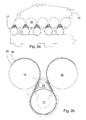
- FIG. 2a shows one dryer group, of which there are several successively in the dryer section of a fiber web machine, as described above.
- the dryer group consists of dryer cylinders 16 and turning rolls 17, via which the dryer fabric 18 is adapted to travel as an endless loop.
- Single fabric run where there is only a single dryer fabric in each dryer group, as presented is used at present to an increasing degree.
- the web travels between the dryer fabric and the heated dryer cylinder.
- the turning roll the web travels on the dryer fabric.
- the turning roll is usually a grooved suction roll, where the vacuum effect achieved in the suction roll keeps the web attached to the dryer fabric.
- web control employs a runnability component 19, which is placed in the pocket space 20 formed by consecutive dryer cylinders and the turning roll.
- the runnability components are represented by the end plates indicated by the diagonal lines. The end plates are used for controlling air flows at the edges of the web.
- Figure 2a illustrates the mere dryer fabric 18 without the web.
- Figure 2b illustrates a runnability component 19 marketed by the applicant under the product name HiRu nTM, where the runnability component 19 is in practice a blow box.
- the blow box contains blow nozzles in the cross direction of the fiber web machine both on the inlet side and outlet side.
- the so-called high vacuum region is limited with respect to the pocket space with a normal vacuum to the vicinity of the dryer fabric by means of a vacuum divider placed in the cross direction of the fiber web machine, and the region is provided with a vacuum by means of suction.
- the region of influence of the vacuum is denoted by the broken line in Figure 2b .
- the runnability component presented is intended for use during production, when the web covers the dryer fabric, inhibiting leakage through the dryer fabric to the runnability component. In this case, the capacity of the runnability component is insufficient for the tail threading of a full width web.
- the applicant has presented that the tail threading of a full width web is possible by arranging blow off blow equipment 23 in the opening gap formed by a dryer cylinder and a dryer fabric for detaching the web.
- the blow off blow is used for blowing off the tail of a full width web from the dryer cylinder 16 and guiding the tail to follow the dryer fabric 18.
- the blow off blows are in use during tail threading, and in the case illustrated in Figure 3a , the tail of the web has already progressed past the dryer cylinders illustrated.
- this invention relates to a method in the tail threading of a full width web in the dryer section of a fiber web machine.
- the dryer section includes successive dryer groups 15, and each dryer group 15 includes dryer cylinders 16 and turning rolls 17 as well as one dryer fabric 18 alternately supported on the dryer cylinder 16 and on the turning roll 17 as a single fabric run.
- the full width web 22 is blown off from the dryer cylinder 16 ( Figures 3b and 4 ).
- the arrangement includes blow off blow equipment 23, which is adapted in the opening gap 21 formed by the dryer cylinder 16, which precedes the turning roll 17, and the dryer fabric 18.
- the blow off blow equipment enables the blow off of the full width web 22 from the dryer cylinder 16.
- the pocket space 20 formed by the turning roll 17 and two dryer cylinders 16 is provided with a vacuum.
- the arrangement includes runnability components 19, which are adapted in the pocket spaces 20 formed by the turning roll 17 and two dryer cylinders 16.
- an intensified vacuum is created in tail threading in the closing gap 24 formed by the dryer fabric 18 and the turning roll 17.
- the arrangement includes vacuum creating devices 25, which are arranged in the closing gap 24 formed by the dryer fabric 18 and the turning roll 17 in order to create an intensified vacuum in full width tail threading.
- the intensified vacuum makes the web, which has been detached by means of the blow off blow equipment, adhere to the surface of the dryer fabric.
- the vacuum created by the runnability components in combination with the turning roll has sufficient time to function, keeping the web and its tail under control. This also avoids fluttering of the web and dropping of the web from the dryer fabric.
- the tail threading of a full width web is possible.
- the intensified vacuum of the closing gap 24 is illustrated in Figure 3b .
- the intensified vacuum preferably extends across the width of full width tail threading. In other words, the intensified vacuum extends across the entire width of the web.
- the intensified vacuum in the closing gap can be used for correcting the instability of the web caused by the previous detaching of the web in the travel direction of the web, and the full width web can be made to settle to the dryer fabric in a stable manner.
- FIG. 4 illustrates another embodiment of the arrangement according to the invention.
- an intensified vacuum is also created in tail threading in the detachment point 26 of the dryer cylinder 16 and the dryer fabric 18.
- the arrangement includes a second set of vacuum creating devices 27, which are placed in the vicinity of the detachment point 26 of the dryer cylinder 16 and the dryer fabric 18.
- the intensified vacuum assists the blow off blow so that immediately after the web has been detached from the dryer cylinder, the web adheres to the surface of the dryer fabric.
- the second set of vacuum creating devices prevents at least some of the air travelling with the dryer fabric from entering the pocket space.
- the first set of vacuum creating devices takes air away from the closing gap, thus avoiding the detachment of the web from the dryer fabric.
- the intensified vacuum can be created in different ways. For example suction devices can be used. However, in the embodiments presented the intensified vacuum is created by blows. It is easy to control the blows, and the necessary components require little installation space.
- the vacuum creating devices 25 and 27 consist of blow pipes 28 and 29, which essentially extend across the entire width of the web 22.
- the blow pipes may have separate nozzles, or the blow pipes may have holes or gaps to form the functional nozzles.
- the preferred dimensioning when using holes is 2 - 4 mm holes at a distribution of 200 - 600 mm.
- the vacuum creating devices 25 and 27 are fastened to the runnability component 19.
- the vacuum creating devices can be installed at the exact desired location.
- the runnability component can be utilized in other ways, too.
- the runnability component 19 is preferably adapted as a flow surface 30. In practice, the flow surface guides the blows and prevents the swirling of air. At the same time, an efficient vacuum is created, and the location of the vacuum can be determined accurately.
- the flow surface 30 is illustrated especially in Figure 4 .
- the runnability component 19 in Figure 4 has two chambers, because the runnability component 19 includes a flow channel 31 for exhaust air.
- the flow channel opens upwards from the pocket space and takes air along with it. In this way, the air brought by the first set of vacuum creating devices exits the pocket space in a controlled manner, and the intensification of the vacuum is enabled.
- the flow channel 31 includes barriers 33 in order to prevent the re-aeration of the pocket space. When the flow channel is closed, the travel of air into the pocket space through the flow channel is prevented during production. In this case, the runnability components work as planned.
- the arrangement according to the invention accomplishes momentarily a greater vacuum than earlier, which is why the tail threading of a full width web is reliable in all situations.
- the vacuum is in the region of 300 - 1,000 Pa, preferably 400 - 600 Pa, which is considerably higher than with conventional runnability components.
- a high capacity, or in practice a high air volume, is primarily only needed at the point of the tail of the web. In the solution according to the invention, the air capacity is directed to wherever it is needed at any given moment, which avoids unnecessary overdimensioning.
- the air volumes and controls of the runnability components are restored to the normal, proven level.
- the runnability components are largely controlled according to the applicant's earlier invention. Air division is changed so that the runnability components of a single dryer group or several dryer groups are separate groups controlled with their own control equipment. At the beginning of tail threading, air is led for example only to the first two dryer groups. No vacuum is needed yet in the other dryer groups, because the tail of the full width web is only approaching. As the web moves on, new dryer groups are opened into operation and, correspondingly, full width tail threading blows are closed where the web already covers the dryer fabric. The progress of the web can be detected for example by means of vacuum measurement in each dryer group.
- the arrangement according to the invention accomplishes the tail threading of a full width web directly from the press section to the end of the dryer section. Moreover, automatic full width tail threading is accomplished starting from a break point without having to commence tail threading all the way from the press section. At the same time, the necessary air volume is reduced, and the structure of the runnability components is simplified.
- the runnability components can be provided with a vacuum by using blowers and the blow pipes can be provided with compressors when more intense intensification is required, but in easier cases a separate blower is sufficient.
- the invention relates to a method in the tail threading of a full width web in the dryer section of a fiber web machine, where the dryer section includes successive dryer groups (R1 - R9).
- Each dryer group (15) includes dryer cylinders (16) and turning rolls (17) as well as one dryer fabric (18) alternately supported on a dryer cylinder (16) and on a turning roll (17) as a single fabric run.
- the full width web (22) is blown off from the dryer cylinder (16).
- the pocket space (20) formed by the turning roll (17) and two dryer cylinders (16) is provided with a vacuum.
- An intensified vacuum is created in tail threading in the closing gap (24) formed by the dryer fabric (18) and the turning roll (17).
- the invention also relates to an arrangement in the tail threading of a full width web in the dryer section of a fiber web machine.
Applications Claiming Priority (1)
| Application Number | Priority Date | Filing Date | Title |
|---|---|---|---|
| FI20115148A FI123016B (fi) | 2011-02-17 | 2011-02-17 | Menetelmä ja sovitelma täysleveän rainan päänviennissä kuiturainakoneen kuivatusosalla |
Publications (1)
| Publication Number | Publication Date |
|---|---|
| EP2489782A1 true EP2489782A1 (en) | 2012-08-22 |
Family
ID=43629820
Family Applications (1)
| Application Number | Title | Priority Date | Filing Date |
|---|---|---|---|
| EP20120152810 Withdrawn EP2489782A1 (en) | 2011-02-17 | 2012-01-27 | Method and arrangement in the tail threading of a full width web in the dryer section of a fiber web machine |
Country Status (3)
| Country | Link |
|---|---|
| EP (1) | EP2489782A1 (fi) |
| CN (1) | CN202644296U (fi) |
| FI (1) | FI123016B (fi) |
Citations (3)
| Publication number | Priority date | Publication date | Assignee | Title |
|---|---|---|---|---|
| EP0479748A1 (en) * | 1990-10-01 | 1992-04-08 | Valmet Corporation | Method and device in the drying section of a paper machine in the threading of the web |
| WO2009141508A1 (en) | 2008-05-22 | 2009-11-26 | Metso Paper, Inc. | Method and arrangement in tail threading of a web in the dryer section of a fiber web machine |
| WO2010084241A1 (en) * | 2009-01-20 | 2010-07-29 | Metso Paper, Inc. | Method and arrangement for facilitating web threading in a paper machine's drying section |
-
2011
- 2011-02-17 FI FI20115148A patent/FI123016B/fi not_active IP Right Cessation
-
2012
- 2012-01-27 EP EP20120152810 patent/EP2489782A1/en not_active Withdrawn
- 2012-02-17 CN CN2012200551068U patent/CN202644296U/zh not_active Expired - Fee Related
Patent Citations (3)
| Publication number | Priority date | Publication date | Assignee | Title |
|---|---|---|---|---|
| EP0479748A1 (en) * | 1990-10-01 | 1992-04-08 | Valmet Corporation | Method and device in the drying section of a paper machine in the threading of the web |
| WO2009141508A1 (en) | 2008-05-22 | 2009-11-26 | Metso Paper, Inc. | Method and arrangement in tail threading of a web in the dryer section of a fiber web machine |
| WO2010084241A1 (en) * | 2009-01-20 | 2010-07-29 | Metso Paper, Inc. | Method and arrangement for facilitating web threading in a paper machine's drying section |
Also Published As
| Publication number | Publication date |
|---|---|
| FI123016B (fi) | 2012-10-15 |
| CN202644296U (zh) | 2013-01-02 |
| FI20115148A0 (fi) | 2011-02-17 |
| FI20115148A (fi) | 2012-08-18 |
Similar Documents
| Publication | Publication Date | Title |
|---|---|---|
| FI95730C (fi) | Yksirivinen kuivausosa ja menetelmä rainan kuivaamiseksi | |
| US5232554A (en) | Threading the web into a twin wire dryer group | |
| FI100544B (fi) | Kuivainlaite rainan kuivaamiseksi | |
| EP1543194B1 (en) | Forming of a paper or board web in a twin-wire former | |
| FI76142C (fi) | Fickventilationsfoerfarande och -anordning i en pappersmaskins maongcylindertork. | |
| CA2325382C (en) | Method and apparatus for controlling the temperature in the drying section of a paper machine | |
| FI67901C (fi) | Foerfarande och anordning i torkpartiet i en pappersmaskin vid styrning av banans spets. | |
| FI82095C (fi) | Foerfarande och anordning i cylindertorken av en pappersmaskin. | |
| FI80103B (fi) | Foerfarande och anordning i cylindertorken av en pappersmaskin, vid vilken ett drag med dubbel vaevnad anvaends. | |
| FI95731C (fi) | Keksintö kohdistuu menetelmään ja laitteeseen paperirainan lepatuksen estämiseksi paperikoneen kuivatusosalla sen kahden yksiviiravientiryhmän välillä | |
| JP2851369B2 (ja) | 抄紙機の乾燥部において使用するウエブの通紙を補強するための方法および装置 | |
| US8117765B2 (en) | Apparatus and method of sealing of a pocket space between drying cylinders in a paper machine or a board machine | |
| NO179263B (no) | Törkeinnretning | |
| EP2489782A1 (en) | Method and arrangement in the tail threading of a full width web in the dryer section of a fiber web machine | |
| US7264693B2 (en) | Apparatus for leading a web threading tail over an empty space | |
| US6916404B2 (en) | Method and apparatus for web threading in a drying section of a paper machine or similar | |
| CA2905562C (en) | A pocket ventilator device and method | |
| WO2010084241A1 (en) | Method and arrangement for facilitating web threading in a paper machine's drying section | |
| EP1337708B1 (en) | Arrangement within a yankee cylinder or the like and a reel-up of a paper machine | |
| FI121715B (fi) | Menetelmä ja laite rainan päänviennissä paperikoneen tai vastaavan kuivatusosassa | |
| FI107064B (fi) | Menetelmä ja laite rainan kulun varmistamiseksi paperikoneen monisylinterikuivattimessa | |
| US6412192B1 (en) | Device and method for ventilating an offset pocket space in a papermaking machine | |
| US6725569B2 (en) | Device and method for ventilating an offset pocket space in a papermaking machine | |
| CA2369401C (en) | Device and method for ventilating an offset pocket space in a papermaking machine | |
| CA2332677C (en) | Device and method for ventilating an offset pocket space in a papermaking machine |
Legal Events
| Date | Code | Title | Description |
|---|---|---|---|
| PUAI | Public reference made under article 153(3) epc to a published international application that has entered the european phase |
Free format text: ORIGINAL CODE: 0009012 |
|
| 17P | Request for examination filed |
Effective date: 20120529 |
|
| AK | Designated contracting states |
Kind code of ref document: A1 Designated state(s): AL AT BE BG CH CY CZ DE DK EE ES FI FR GB GR HR HU IE IS IT LI LT LU LV MC MK MT NL NO PL PT RO RS SE SI SK SM TR |
|
| AX | Request for extension of the european patent |
Extension state: BA ME |
|
| 17Q | First examination report despatched |
Effective date: 20131008 |
|
| RAP1 | Party data changed (applicant data changed or rights of an application transferred) |
Owner name: VALMET TECHNOLOGIES, INC. |
|
| STAA | Information on the status of an ep patent application or granted ep patent |
Free format text: STATUS: THE APPLICATION IS DEEMED TO BE WITHDRAWN |
|
| 18D | Application deemed to be withdrawn |
Effective date: 20150804 |