EP2489587A2 - Regler für Unterwasserbeatmungsvorrichtung - Google Patents
Regler für Unterwasserbeatmungsvorrichtung Download PDFInfo
- Publication number
- EP2489587A2 EP2489587A2 EP12154395A EP12154395A EP2489587A2 EP 2489587 A2 EP2489587 A2 EP 2489587A2 EP 12154395 A EP12154395 A EP 12154395A EP 12154395 A EP12154395 A EP 12154395A EP 2489587 A2 EP2489587 A2 EP 2489587A2
- Authority
- EP
- European Patent Office
- Prior art keywords
- regulator
- flexible diaphragm
- chamber
- tubular element
- box
- Prior art date
- Legal status (The legal status is an assumption and is not a legal conclusion. Google has not performed a legal analysis and makes no representation as to the accuracy of the status listed.)
- Withdrawn
Links
- 230000029058 respiratory gaseous exchange Effects 0.000 title claims abstract description 15
- XLYOFNOQVPJJNP-UHFFFAOYSA-N water Substances O XLYOFNOQVPJJNP-UHFFFAOYSA-N 0.000 claims abstract description 38
- 230000001105 regulatory effect Effects 0.000 claims abstract description 17
- 238000007599 discharging Methods 0.000 claims abstract description 8
- 238000011144 upstream manufacturing Methods 0.000 claims description 4
- 239000012528 membrane Substances 0.000 claims description 2
- 230000008030 elimination Effects 0.000 description 3
- 238000003379 elimination reaction Methods 0.000 description 3
- 230000009182 swimming Effects 0.000 description 3
- 206010049565 Muscle fatigue Diseases 0.000 description 2
- 230000015572 biosynthetic process Effects 0.000 description 2
- 239000013078 crystal Substances 0.000 description 2
- 230000009189 diving Effects 0.000 description 1
- 230000005484 gravity Effects 0.000 description 1
Images

Classifications
-
- B—PERFORMING OPERATIONS; TRANSPORTING
- B63—SHIPS OR OTHER WATERBORNE VESSELS; RELATED EQUIPMENT
- B63C—LAUNCHING, HAULING-OUT, OR DRY-DOCKING OF VESSELS; LIFE-SAVING IN WATER; EQUIPMENT FOR DWELLING OR WORKING UNDER WATER; MEANS FOR SALVAGING OR SEARCHING FOR UNDERWATER OBJECTS
- B63C11/00—Equipment for dwelling or working underwater; Means for searching for underwater objects
- B63C11/02—Divers' equipment
- B63C11/18—Air supply
- B63C11/22—Air supply carried by diver
- B63C11/2227—Second-stage regulators
Definitions
- the present invention relates to regulators for underwater breathing apparatus.
- an underwater breathing regulator or more specifically the second stage thereof, comprises a box-like body in which is formed a chamber having a first tubular element for sealed connection to a mouthpiece, a second tubular element provided with a regulating valve and adapted to be connected to a hose for supplying air to the inside of the regulator chamber, a conduit for the discharge of expired air and any residual water, and a front aperture closed by a flexible diaphragm on which is positioned a cover having a set of holes or apertures adapted to allow the water to come into contact with the outer surface of this flexible diaphragm.
- This flexible diaphragm interacts, by means of a suitable lever positioned in the regulator chamber, with the regulating valve which is placed in the tubular element for supplying air to the regulator.
- Another negative aspect of conventional regulators is the positioning of the hose which is connected downstream to the tubular air supply element and upstream to the first regulator stage located at the outlet of the cylinder or cylinders.
- the tubular air supply element in a conventional regulator is positioned laterally relative to the regulator and emerges perpendicularly therefrom, and consequently the hose connected to this regulator also emerges from the tubular connecting element in the same lateral and perpendicular direction, and must therefore be curved through a large angle in order to be connected to the first stage at the outlet of the cylinders.
- This positioning of the hose gives rise to numerous problems, including excessive overall dimensions which cause a considerable degree of friction with the water, and the risk that the hose may be entangled in obstacles in the course of the diver's underwater movements.
- a further disadvantage of known regulators is that the elimination of any residual water from the regulator chamber and towards the discharge conduit can take place conveniently only when the diver is in an upright position or is looking up towards the surface of the water, whereas in other cases, for example in the swimming position, the water accumulates near the front diaphragm, creating considerable difficulties for its elimination.
- the difficulty in expelling residual water from the inside of the regulator may give rise to the constant presence of water droplets in the regulator, which cause problems during respiration and, if diving takes place in cold water, can even cause the formation of ice crystals in the regulator, with obvious risks for the diver.
- the object of the present invention is therefore to provide a regulator for underwater breathing apparatus which overcomes the drawbacks and disadvantages of the aforementioned known regulators.
- a regulator for underwater breathing apparatus comprising a box-like body in which is formed a chamber having a first tubular element for connection to a mouthpiece, a second tubular element provided with a regulating valve for supplying air to the inside of the regulator chamber, a conduit for discharging expired air and any residual water, and an aperture on which is positioned a flexible diaphragm surmounted by a cover provided with a set of holes or apertures adapted to allow water to come into contact with the outer surface of the flexible diaphragm, this flexible diaphragm interacting by suitable means with the regulating valve, characterized in that the diaphragm and the cover lie on, or are parallel to, a plane facing upwards and inclined forwards relative to a generally upright position of the diver; a plurality of water inlet apertures is formed behind the cover.
- a second aspect of the present invention is a regulator for underwater breathing apparatus in which the tubular element for connection to the air supply hose is inclined to the rear, in other words towards the tubular element for connection to the mouthpiece.
- a further aspect of the present invention is a regulator in which the chamber inside the box-like body is of truncated conical shape with an increasing cross section, inclined towards the conduit for discharging expired air and any residual water.
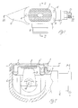
- the number 1 indicates the box-like body of a regulator for underwater breathing apparatus according to the present invention.
- This box-like body 1 comprises an internal chamber 6, on one side of which is formed an aperture 7 closed by a flexible diaphragm 2.
- This diaphragm 2 is fixed to the annular edge of the box-like body 1 by means of a removable cover 3.
- the cover 3 is fixed to the box-like body 1, by means of pins 4 for example, and comprises a set of holes 5 which are suitably designed to allow water to enter the chamber 6 of the regulator and create the correct pressure difference between the surfaces of the diaphragm 2.
- a first tubular element 8 is formed on one side of the box-like body 1 and in one piece with the latter, and can be connected in a sealed way to the mouthpiece which is not shown in the drawings.
- a second tubular element 9 for admitting air into the chamber 6 of the regulator is formed on another side of the box-like body 1 and in one piece with the latter. This tubular element 9 is adapted to be connected, by means of its threaded terminal part 10, to a hose, not shown in the drawings, which is connected upstream to the first stage of the regulator and then to the air supply cylinder or cylinders.
- This conduit 11 is closed by a check valve 12 in the chamber 6 of the regulator.
- the flexible diaphragm 2 interacts with a lever 13 connected to the plug of an air flow regulating valve 14 located in the tubular air inlet element 9.
- the diaphragm 2 bends resiliently towards the inside of the chamber 6 so as to lower the lever 13, with respect to the rest position of Fig. 3 for example, and the plug of the regulating valve 14 opens to allow the air drawn from the first stage located at the outlet of the cylinders to pass through the hose and enter the chamber 6 through the tubular element 9.
- the flexible diaphragm 2 is returned to the position of Fig. 3 , the plug of the valve 14, being provided with suitable resilient return means, is closed, and the lever 13 also moves to the position of Fig. 3 .
- the flexible diaphragm 2 and the cover 3 face upwards relative to a generally upright position of the diver wearing the present regulator, and are parallel to a plane M (see Fig. 2 ) which is substantially orthogonal to a plane P in which the aperture of the tubular element 8 for connection to the mouthpiece lies.
- the cover 3' and the flexible diaphragm 2 are parallel to a plane M' (see Fig. 5 ) which is inclined forwards relative to the plane M of the embodiment of Fig. 2 .
- the cover 3' advantageously has a front or anterior surface without water inlet holes, to avoid undesired forces of the water on the diaphragm and the consequent risks of free flow.
- this cover 3' is provided with a set of water inlet apertures 5' which are located on the rear part of the box-like body 1 of the regulator. Consequently, these apertures face the tubular element 8 for connection to the mouthpiece, and are therefore shielded from any underwater currents.
- the optimal angle of inclination A of this plane M' relative to the plane M is approximately 35°.
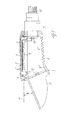
- the discharge conduit 11 is positioned on one side of the body 1 of the regulator, in particular on the side opposite that on which the tubular hose connection element 9 is formed. This positioning of the discharge conduit 11 facilitates the operation of expiration by the diver. Additionally, this discharge conduit 11 is inclined downwards at an angle B relative to the plane M, as shown in Fig. 3 , and faces to the rear, in other words towards the back of the diver's neck, as shown in Fig. 5 .
- the angle B of inclination of the conduit 11 relative to the plane M is approximately 35°.
- Fig. 3 also shows another important characteristic of the present regulator, namely the double-taper truncated conical shape of the inside chamber 6 of the body of the regulator.
- the inner cross section of the chamber 6 increases towards the discharge valve 12 located upstream of the discharge conduit, and has a first portion 6' having a certain degree of taper and inclination towards the conduit 11 and a second portion 6", located in the proximity of the discharge valve 12 and having a greater inclination than the first portion 6'.
- This shape of the inside chamber 6 of the box-like body 1 of the regulator facilitates the elimination of any residual water from the regulator even when the diver is not in an upright position, and therefore even when the diver is, for example, in a swimming position.
- the water is conveyed towards the discharge valve 12 regardless of the position of the diver, and any water droplets, which often cause problems during breathing and which can cause the formation of ice crystals in the regulation during dives in cold water, are advantageously discharged from the conduit 11.
- Fig. 4 shows a further important characteristic of the present regulator, in which the tubular hose connection element 9 is inclined to the rear, in other words towards the tubular mouthpiece connection element 8, relative to the lateral perpendicular direction D of known tubular connecting elements.
- the angle C of inclination of this tubular element 9 is preferably variable between 30° and 60°.
- This tubular element 9 can also be slightly inclined upwards when the diver is in an upright position.
- the lever 13' must be made with a certain amount of single or double curvature, so as to follow the shape of the box-like body 1 of the present regulator, which has an optimum degree of compactness.
- the tubular element 9 inclined to the rear at a certain angle C.
- the hose connected to this tubular element 9 has much smaller overall dimensions than the hose of a conventional regulator, in which, as mentioned above, the hose runs in a lateral and perpendicular outward direction D.
- the smaller overall dimensions of the rearwardly inclined hose according to the present invention decrease the friction in water and reduce the possibility of the diver's becoming entangled in any obstacles.
- the inclined hose is much more convenient in use and forms a smaller lever arm than the perpendicular hose of a conventional regulator, and therefore the diver can hold the regulator firmly in his mouth without excessive muscle fatigue.
- the rearward inclination of the hose also reduces the risks of contact between the hose and the diver's shoulder, the regulator is more balanced overall than conventional regulators, and its weight is advantageously reduced.
Landscapes
- Health & Medical Sciences (AREA)
- General Health & Medical Sciences (AREA)
- Pulmonology (AREA)
- Engineering & Computer Science (AREA)
- Mechanical Engineering (AREA)
- Ocean & Marine Engineering (AREA)
- Respiratory Apparatuses And Protective Means (AREA)
- Electrical Discharge Machining, Electrochemical Machining, And Combined Machining (AREA)
Applications Claiming Priority (1)
| Application Number | Priority Date | Filing Date | Title |
|---|---|---|---|
| IT000018A ITGE20110018A1 (it) | 2011-02-17 | 2011-02-17 | " erogatore per apparecchi respiratori subacquei " |
Publications (2)
| Publication Number | Publication Date |
|---|---|
| EP2489587A2 true EP2489587A2 (de) | 2012-08-22 |
| EP2489587A3 EP2489587A3 (de) | 2012-11-21 |
Family
ID=43976011
Family Applications (1)
| Application Number | Title | Priority Date | Filing Date |
|---|---|---|---|
| EP12154395A Withdrawn EP2489587A3 (de) | 2011-02-17 | 2012-02-08 | Regler für Unterwasserbeatmungsvorrichtung |
Country Status (4)
| Country | Link |
|---|---|
| US (1) | US20120211009A1 (de) |
| EP (1) | EP2489587A3 (de) |
| JP (1) | JP2012171615A (de) |
| IT (1) | ITGE20110018A1 (de) |
Cited By (1)
| Publication number | Priority date | Publication date | Assignee | Title |
|---|---|---|---|---|
| WO2019043552A1 (en) * | 2017-08-31 | 2019-03-07 | Xdeep Sp. Z O.O. | DIVERSION REGULATOR FIRST FLOOR |
Family Cites Families (7)
| Publication number | Priority date | Publication date | Assignee | Title |
|---|---|---|---|---|
| US4356820A (en) * | 1980-08-18 | 1982-11-02 | Sherwood-Selpac Corporation | Heat reclaimer for demand regulator |
| US4503852A (en) * | 1981-08-24 | 1985-03-12 | Tony Christianson | Pilot controlled regulator second stage |
| US4603833A (en) * | 1982-06-14 | 1986-08-05 | Tony Christianson | Inlet valve for breathing apparatus second stage regulators |
| US5251618A (en) * | 1987-09-30 | 1993-10-12 | Tony Christianson | Regulator second stage for scuba |
| JP2001088780A (ja) * | 1999-09-24 | 2001-04-03 | Tabata:Kk | ダイビング用レギュレーター |
| IT250804Y1 (it) * | 2000-08-18 | 2003-10-14 | Htm Sport Spa | Erogatore per apparecchi respiratori subacquei. |
| PT2207715E (pt) * | 2007-10-29 | 2014-06-03 | Poseidon Diving Systems | Peça de boca para um aparelho de respiração |
-
2011
- 2011-02-17 IT IT000018A patent/ITGE20110018A1/it unknown
-
2012
- 2012-02-08 EP EP12154395A patent/EP2489587A3/de not_active Withdrawn
- 2012-02-08 US US13/368,502 patent/US20120211009A1/en not_active Abandoned
- 2012-02-15 JP JP2012030064A patent/JP2012171615A/ja active Pending
Non-Patent Citations (1)
| Title |
|---|
| None |
Cited By (4)
| Publication number | Priority date | Publication date | Assignee | Title |
|---|---|---|---|---|
| WO2019043552A1 (en) * | 2017-08-31 | 2019-03-07 | Xdeep Sp. Z O.O. | DIVERSION REGULATOR FIRST FLOOR |
| PL422714A1 (pl) * | 2017-08-31 | 2019-03-11 | Xdeep Spolka Z Ograniczona Odpowiedzialnoscia | Pierwszy stopień automatu nurkowego |
| CN110267873A (zh) * | 2017-08-31 | 2019-09-20 | 埃克斯皮有限责任公司 | 一级头潜水调节器 |
| US11613334B2 (en) | 2017-08-31 | 2023-03-28 | Xdeep Spolka Z Ograniczona Odpowiedzialnoscia | First-stage diving regulator |
Also Published As
| Publication number | Publication date |
|---|---|
| JP2012171615A (ja) | 2012-09-10 |
| ITGE20110018A1 (it) | 2012-08-18 |
| US20120211009A1 (en) | 2012-08-23 |
| EP2489587A3 (de) | 2012-11-21 |
Similar Documents
| Publication | Publication Date | Title |
|---|---|---|
| AU2019200673B2 (en) | Diving mask having a built-in snorkel | |
| CN109204743B (zh) | 用于表面浮潜的面罩 | |
| US20100229858A1 (en) | Aquatic headgear | |
| EP3681793B1 (de) | Volltauchmaske | |
| FI3522966T3 (fi) | Potilasrajapintoja | |
| JP2019528992A5 (de) | ||
| JPH0656081A (ja) | ダイビングフェイスマスク | |
| US4467797A (en) | Breathing effort reduction device for scuba gear | |
| US8418689B1 (en) | Exhaust air transfer device for open system underwater diving | |
| EP3256379B1 (de) | Druckmindernde zweite stufe für unterwassereinsatz | |
| EP2489587A2 (de) | Regler für Unterwasserbeatmungsvorrichtung | |
| JP5155167B2 (ja) | 潜水装具と共に使用する泡そらし装置 | |
| CN208882082U (zh) | 吸气管长度可调节的浮潜面罩 | |
| US20070131227A1 (en) | Aquatic headgear | |
| US20040035415A1 (en) | Breathing apparatus | |
| CN210852852U (zh) | 一种浮潜面罩 | |
| CN210191785U (zh) | 呼吸管 | |
| US20110277755A1 (en) | Snorkel | |
| EP4247704B1 (de) | Schwimmmaske | |
| ITGE20120029U1 (it) | " erogatore per apparecchi respiratori subacquei " | |
| KR200199702Y1 (ko) | 수직위치 복원력이 있는 부유물을 이용한 수영인의 깊은수중 호흡기 | |
| HK1261547A1 (en) | Mask for surface snorkeling | |
| HK1261547B (en) | Mask for surface snorkeling | |
| JPH0930491A (ja) | シュノーケル | |
| JPH06247383A (ja) | ダイビングフェイスマスク |
Legal Events
| Date | Code | Title | Description |
|---|---|---|---|
| PUAI | Public reference made under article 153(3) epc to a published international application that has entered the european phase |
Free format text: ORIGINAL CODE: 0009012 |
|
| AK | Designated contracting states |
Kind code of ref document: A2 Designated state(s): AL AT BE BG CH CY CZ DE DK EE ES FI FR GB GR HR HU IE IS IT LI LT LU LV MC MK MT NL NO PL PT RO RS SE SI SK SM TR |
|
| AX | Request for extension of the european patent |
Extension state: BA ME |
|
| PUAL | Search report despatched |
Free format text: ORIGINAL CODE: 0009013 |
|
| AK | Designated contracting states |
Kind code of ref document: A3 Designated state(s): AL AT BE BG CH CY CZ DE DK EE ES FI FR GB GR HR HU IE IS IT LI LT LU LV MC MK MT NL NO PL PT RO RS SE SI SK SM TR |
|
| AX | Request for extension of the european patent |
Extension state: BA ME |
|
| RIC1 | Information provided on ipc code assigned before grant |
Ipc: B63C 11/22 20060101AFI20121016BHEP |
|
| STAA | Information on the status of an ep patent application or granted ep patent |
Free format text: STATUS: THE APPLICATION IS DEEMED TO BE WITHDRAWN |
|
| 18D | Application deemed to be withdrawn |
Effective date: 20130522 |