EP2489558A2 - Pretensioner, seat belt retractor with pretensioner, and seat belt unit including seat belt retractor - Google Patents
Pretensioner, seat belt retractor with pretensioner, and seat belt unit including seat belt retractor Download PDFInfo
- Publication number
- EP2489558A2 EP2489558A2 EP12001104A EP12001104A EP2489558A2 EP 2489558 A2 EP2489558 A2 EP 2489558A2 EP 12001104 A EP12001104 A EP 12001104A EP 12001104 A EP12001104 A EP 12001104A EP 2489558 A2 EP2489558 A2 EP 2489558A2
- Authority
- EP
- European Patent Office
- Prior art keywords
- pretensioner
- gas generator
- blocking
- blocking member
- discharge hole
- Prior art date
- Legal status (The legal status is an assumption and is not a legal conclusion. Google has not performed a legal analysis and makes no representation as to the accuracy of the status listed.)
- Granted
Links
- 230000000903 blocking effect Effects 0.000 claims abstract description 168
- 230000007246 mechanism Effects 0.000 claims abstract description 10
- 238000004891 communication Methods 0.000 claims abstract description 7
- 230000005540 biological transmission Effects 0.000 claims description 12
- 230000000694 effects Effects 0.000 description 12
- 230000002093 peripheral effect Effects 0.000 description 6
- XEEYBQQBJWHFJM-UHFFFAOYSA-N Iron Chemical compound [Fe] XEEYBQQBJWHFJM-UHFFFAOYSA-N 0.000 description 4
- 238000005452 bending Methods 0.000 description 4
- 238000007599 discharging Methods 0.000 description 4
- 238000000034 method Methods 0.000 description 3
- 230000000452 restraining effect Effects 0.000 description 3
- 230000000717 retained effect Effects 0.000 description 3
- 101000856746 Bos taurus Cytochrome c oxidase subunit 7A1, mitochondrial Proteins 0.000 description 2
- 230000009471 action Effects 0.000 description 2
- 238000006073 displacement reaction Methods 0.000 description 2
- 229910052742 iron Inorganic materials 0.000 description 2
- 229910052751 metal Inorganic materials 0.000 description 2
- 239000002184 metal Substances 0.000 description 2
- 239000000853 adhesive Substances 0.000 description 1
- 230000001070 adhesive effect Effects 0.000 description 1
- 229910052782 aluminium Inorganic materials 0.000 description 1
- XAGFODPZIPBFFR-UHFFFAOYSA-N aluminium Chemical compound [Al] XAGFODPZIPBFFR-UHFFFAOYSA-N 0.000 description 1
- 230000004323 axial length Effects 0.000 description 1
- 239000000470 constituent Substances 0.000 description 1
- 230000001419 dependent effect Effects 0.000 description 1
- 230000003993 interaction Effects 0.000 description 1
- 239000000463 material Substances 0.000 description 1
- 238000012986 modification Methods 0.000 description 1
- 230000004048 modification Effects 0.000 description 1
- 239000011347 resin Substances 0.000 description 1
- 229920005989 resin Polymers 0.000 description 1
- 238000011144 upstream manufacturing Methods 0.000 description 1
Images


Classifications
-
- B—PERFORMING OPERATIONS; TRANSPORTING
- B60—VEHICLES IN GENERAL
- B60R—VEHICLES, VEHICLE FITTINGS, OR VEHICLE PARTS, NOT OTHERWISE PROVIDED FOR
- B60R22/00—Safety belts or body harnesses in vehicles
- B60R22/34—Belt retractors, e.g. reels
- B60R22/46—Reels with means to tension the belt in an emergency by forced winding up
- B60R22/4628—Reels with means to tension the belt in an emergency by forced winding up characterised by fluid actuators, e.g. pyrotechnic gas generators
- B60R2022/4642—Reels with means to tension the belt in an emergency by forced winding up characterised by fluid actuators, e.g. pyrotechnic gas generators the gas directly propelling a flexible driving means, e.g. a plurality of successive masses, in a tubular chamber
-
- B—PERFORMING OPERATIONS; TRANSPORTING
- B60—VEHICLES IN GENERAL
- B60R—VEHICLES, VEHICLE FITTINGS, OR VEHICLE PARTS, NOT OTHERWISE PROVIDED FOR
- B60R22/00—Safety belts or body harnesses in vehicles
- B60R22/34—Belt retractors, e.g. reels
- B60R22/46—Reels with means to tension the belt in an emergency by forced winding up
- B60R22/4628—Reels with means to tension the belt in an emergency by forced winding up characterised by fluid actuators, e.g. pyrotechnic gas generators
- B60R2022/4661—Reels with means to tension the belt in an emergency by forced winding up characterised by fluid actuators, e.g. pyrotechnic gas generators comprising venting means, e.g. for avoiding overpressure in case of fire or for allowing return motion with energy absorption
Definitions
- Embodiments described herein relate to a pretensioner, a seatbelt retractor, and a seatbelt unit that activates the seatbelt retractor.
- Various seatbelt retractors that include a pretensioner have thus far been developed for use in a seatbelt unit provided in a vehicle such as an automobile.
- the pretensioner is configured so as to rotate a spool of the seatbelt retractor in a direction to retract the seatbelt with a gas generated by a gas generator at an initial stage of an emergency case, to thereby take up the seatbelt around the spool. This action quickly removes slack of the seatbelt and gives higher tension to the seatbelt, thus increasing the restraining force of the seatbelt with respect to the occupant.
- An example of conventional pretensioners includes a plurality of force transmission members composed of balls accommodated in a pipe, and the force transmission members are made to move by the pressure of the gas generated by the gas generator inside of the pipe, so as to be pressed against a plurality of pressure-receiving portions formed of a lever of a link gear, so that the spool is made to rotate in the direction to retract the seatbelt by the rotation of the link gear (for example, see JP-A-2001-63520 ).
- the pipe includes an hole that allows communication between outside and inside of the pipe, and the hole is blocked by a blocking member.
- the excessive gas pressure acts to remove the blocking member so as to open the hole, thereby discharging the gas out of the pipe.
- JP-A-2001-63520 A technique of discharging the gas out of the pipe is disclosed in JP-A-2001-63520 .
- the technique of discharging the gas according to JP-A-2001-63520 is only intended to discharge the gas utilizing the gas pressure when the gas pressure inside of the pipe excessively increases so as to exceed the predetermined pressure. Accordingly, in the case where the gas pressure inside of the pipe has not increased beyond the predetermined pressure during the operation of the pretensioner, the gas pressure resides in the pipe after the operation of the pretensioner is finished, unless a piston is removed from the pipe. Therefore, the technique of discharging the gas according to JP-A-2001-63520 is unsuitable for solving the foregoing problem. When the pretensioner is activated, actually the gas pressure inside of the pipe often remains below the predetermined pressure during the operation of the pretensioner.
- the present invention provides a pretensioner as defined in claim 1.
- the dependent claims define preferred embodiments of the invention.
- One of illustrative aspects of the present invention is to provide a pretensioner from which a gas residing in a pipe can be easily discharged out of the pipe after the operation of the pretensioner is finished, a seatbelt retractor with the pretensioner, and a seatbelt unit including the seatbelt retractor.
- a pretensioner includes: a pipe; a gas generator that generates a gas in the pipe in an emergency case; a gas generator mount on which the gas generator is mounted; a spool driving mechanism that rotates a spool in a direction to retract a seatbelt by the gas generated by the gas generator in the emergency case; a discharge hole formed in the pipe so as to allow communication between inside and outside of the pipe; and a blocking member configured to block the discharge hole from inside of the pipe, the blocking member being configured to open the discharge hole when the blocking member is pressed from outside of the pipe with a pressing force equal to or greater than a given pressing force.
- the pretensioner configured as above according to the present invention includes the blocking member that blocks the discharge hole of the pipe from inside thereof and opens the discharge hole upon being moved by a pressing force greater than the predetermined pressing force from outside of the pipe.
- Such a configuration allows, the gas inside of the pipe to be easily discharged outwardly, simply by pressing the blocking member thereby opening the discharge hole, after the operation of the pretensioner.
- the generated gas serves to press the blocking member in the direction to more air-tightly block the discharge hole, and hence the blocking member can more effectively block the discharge hole during the operation of the pretensioner.
- Such an arrangement suppresses the pressure loss of the generated gas and allows the occupants to be more effectively restrained.
- Providing the fitting portion and the blocking portion on the blocking member separately from each other enables the fitting portion to more effectively support the blocking member, and allows the blocking portion to more effectively block the discharge hole.
- forming the blocking projection that intrudes into the discharge hole on the blocking portion allows the discharge hole to be more air-tightly blocked.
- the seatbelt retractor and the seatbelt unit according to the present invention include the pretensioner according to the present invention. Accordingly, the gas inside of the gas generator mount and the pipe can be easily discharged outwardly after the operation of the pretensioner. Consequently, the vehicle such as an automobile including the pretensioner that has been activated can be easily demolished to recycle the parts used in the vehicle.
- FIG. 1 is a schematic perspective view showing a seatbelt unit including a seatbelt retractor with a pretensioner according to a first example of the embodiment of the present invention.
- the seatbelt unit 1 is basically the same as a conventionally known three-point seatbelt unit.
- a reference numeral 1 designates the seatbelt unit
- 2 designates a vehicle seat
- 3 designates a seatbelt retractor located close to the vehicle seat
- 4 designates a seatbelt that can be withdrawably retracted in the seatbelt retractor 3 and including a belt anchor 4a attached to a leading end thereof via which the seatbelt 4 is fixed to the vehicle floor or the vehicle seat 2
- 5 designates a guide anchor that guides the seatbelt 4 withdrawn from the seatbelt retractor 3 to a shoulder of the occupant
- 6 designates a tongue slidably supported by the seatbelt 4 extending from the guide anchor
- 7 designates a buckle fixed to the vehicle floor or the vehicle seat 2 and in which the tongue 6 is to be removably inserted for connection.
- the fastening and releasing operation of the seatbelt 4 of the seatbelt unit 1 is
- the seatbelt retractor 3 may be either a conventionally known emergency locking seatbelt retractor (ELR) or a conventionally known automatic locking seatbelt retractor (ALR).
- the seatbelt retractor 3 includes a pretensioner.
- the pretensioner is activated, as a conventionally known pretensioner is, in an emergency case such as collision in which a deceleration far greater than that experienced during a normal driving has been applied to a vehicle, so as to rotate a spool (not shown) of the seatbelt retractor 3 in a direction to retract the seatbelt (hereinafter, seatbelt retracting direction) to thereby take up the seatbelt 4 by a predetermined length thus increasing the restraining force of the seatbelt with respect to the occupant.
- ELR emergency locking seatbelt retractor
- ALR automatic locking seatbelt retractor
- Fig. 2 is a partially cut away side view of the seatbelt retractor including the pretensioner according to the first example shown in Fig. 1 .
- the pretensioner 8 according to the first example is supported by a frame 9 of the seatbelt retractor 3.
- the frame 9 includes a base portion 9a located on the side of the vehicle chamber (left side in Fig. 2 ) so as to be attached to the vehicle body, and a pair of side walls 9b, 9c formed by bending a portion of the base portion 9a.
- the pretensioner 8 includes a pipe 10, and a guide member 11 is provided at a leading end portion 10a of the pipe 10.
- the leading end portion 10a of the pipe 10 and the guide member 11 are attached to a pipe mount 23 fixed to the side wall 9b with a fixture such as a bolt.
- a cutaway portion 10c is formed on the leading end portion 10a of the pipe 10, so as to allow communication between inside and outside of the pipe 10 and extending in a longitudinal direction of the pipe 10.
- the pipe 10 stores therein a plurality of balls 12a made of a metal such as iron or aluminum, and a plurality of force transmission members 12 constituted of a piston (not shown) that presses the balls 12a with a gas pressure, the balls 12a and the force transmission members 12 being movable and disposed in contact with each other.
- a base end portion 10b of the pipe 10 is formed in a larger diameter than the force transmission member storage portion of the pipe 10, and constitutes a gas generator mount 13.
- a gas generator 14 is mounted on the gas generator mount 13.
- the pretensioner 8 includes a case body (not shown) attached to the side wall 9b of the frame 9.
- the case body includes a link gear 15 mounted so as to rotate and to move to the right in Fig. 2 .
- the link gear 15 includes a plurality of inner teeth 15a formed on an inner circumferential surface thereof.
- the link gear 15 is formed so as to partially intrude into the pipe 10 through the cutaway portion 10c of the pipe 10.
- the link gear 15 includes a generally arcuate stopper 16 disposed in contact with a first (leading) one of the balls 12a in a normal state (while the pretensioner 8 is not activated) and having an outer peripheral edge of a predetermined circumferential length (corresponding to the pressure-receiving portion according to the present invention), and a plurality (in the first example, six) of generally triangular levers 17 (corresponding to the pressure-receiving portion according to the present invention), the stopper 16 and the levers 17 being formed so as to project from an outer circumferential surface of the link gear 15.
- the stopper 16 and all of the levers 17 can intrude into the pipe 10 through the cutaway portion 10c.
- a pinion 19 is attached to a rotary shaft 18 of a locking base (not shown) of the seatbelt retractor 3, so as to rotate interlocked with the rotary shaft 18 (here, the pinion 19 may be attached to a rotary shaft of the spool (not shown) of the seatbelt retractor 3, so as to rotate interlocked with the rotary shaft).
- the locking base is employed in the conventionally known ELR and ALR. The locking base rotates, in the normal state, interlocked with the spool of the seatbelt retractor 3 that takes up the seatbelt 4, and is locked by a lock mechanism to be activated in the emergency case to thereby inhibit the rotation of the spool in the direction to withdraw the seatbelt.
- the ELR that employs the pretensioner including the plurality of balls and the locking base can be found, for example, in Japanese Unexamined Patent Application Publication No. 2001-233172 , and hence detailed description of the locking base will not be made herein since the operation thereof can be understood from Japanese Unexamined Patent Application Publication No. 2001-233172 .
- the pinion 19 includes a plurality of outer teeth 19a.
- the outer teeth 19a of the pinion 19 are to be engaged with the inner teeth 15a of the link gear 15.
- the link gear 15 In a normal state, the link gear 15 is retained by shear pins 20 at a standby position shown in Fig. 2 . While the link gear 15 is at the standby position the inner teeth 15a are not engaged with the outer teeth 19a, but spaced therefrom.
- the pretensioner 8 is activated so that a pressing force originating from the pressure of the gas generated by the gas generator 14 is applied to the force transmission members 12, and the force transmission members 12 apply a rotational driving force and a linear displacement force to the link gear 15. Resultantly the shear pins 20 undergo a shear failure and the link gear 15 is moved to an operational position shown in Fig. 3(a) . When the link gear 15 comes to the operational position, the inner teeth 15a are engaged with the outer teeth 19a.
- the link gear 15 and the pinion 19 are rotationally coupled, such that the rotary shaft 18, hence the spool, is caused to rotate in the seatbelt retracting direction through the plurality of force transmission members 12, the link gear 15, and the pinion 19 by the pressing force originating from the pressure of the gas generated by the gas generator 14.
- the plurality of force transmission members 12, the link gear 15, and the pinion 19 constitute the spool driving mechanism according to the present invention.
- the gas generator 14 includes a case 14a of a stepped cylindrical shape, as shown in Fig. 4(a) .
- a planar surface 14b is formed on an outer circumferential surface of an end portion of the case 14a on a gas-injecting side (lower end portion in Fig. 4(a) ).
- An inner circumferential surface of the case 14a opposite the planar surface 14b may be similarly formed in a planar surface, or in a cylindrical shape.
- the gas generator mount 13 includes a planar portion 13a.
- An outer surface 13a 1 and an inner surface 13a 2 of the planar portion 10 are both formed in a planar surface as shown in Figs. 4(c) and 4(d) .
- the planar portion 13a includes a discharge hole 13b that allows communication between outside and inside of the gas generator mount 13 (in other words, pipe 10).
- a blocking member 25 formed of a metal such as iron or a resin in a thin flat plate of a predetermined shape (in this example, rectangular) is joined to the planar surface 14b of the case 14a of the gas generator 14, via an adhesive or the like (indicated by dash-dot-dot lines in Figs. 4(a) and 4(b) ).
- the blocking member 25 is located so as to oppose the entirety of the discharge hole 13b when the gas generator 14 is fitted in the gas generator mount 13. Accordingly, when the gas generator 14 is fitted in the gas generator mount 13 as shown in Figs.
- the outer surface of the blocking member 25 is brought into contact with the inner surface 13a 2 of the gas generator mount 13 of the pipe 10, so as to block the discharge hole 13b from inside of the gas generator mount 13 (in other words, from inside of the pipe 10).
- the outer surface of the blocking member 25 constitutes a blocking surface 25b 1 that blocks the discharge hole 13b.
- the blocking member 25 is pressed, while being disposed so as to block the discharge hole 13b, by a pressing device (not shown) such as a tool from outside of the gas generator mount 13 (outside of the pipe 10) through the discharge hole 13b, with a pressing force F equal to or greater than a predetermined pressing force as shown in Fig. 4(d) , the discharge hole 13b is opened.
- a pressing device such as a tool from outside of the gas generator mount 13 (outside of the pipe 10)
- a predetermined region of the case 14a of the gas generator 14 including the portion where the blocking member 25 is attached is concavely deformed upon being pressed with the pressing force F equal to or greater than the predetermined pressing force, and the blocking member 25 is displaced while being deformed, so that the blocking surface 25b 1 is separated from the inner surface 13a 2 of the gas generator mount 13.
- the discharge hole 13b is opened so as to allow communication between outside and inside of the discharge hole 13b.
- the operation of the pretensioner 8 configured as above according to the first example is basically the same as that of the conventional pretensioner that employs the plurality of ball, up to the stage where the spool of the seatbelt retractor 3 is caused to rotate in the seatbelt retracting direction in an emergency case.
- the link gear 15 is retained at the standby position as shown in Fig. 2 . Accordingly, the inner teeth 15a of the link gear 15 are kept from being engaged with the outer teeth 19a of the pinion 19. Also, the first ball 12a is retained in contact with a lateral face 16a of the stopper 16 on an upstream side in the rotating direction of the link gear 15 (counterclockwise in Fig. 2 , i.e., the seatbelt retracting direction). The subsequent balls 12a are sequentially in contact with the adjacent ones. In such a state, the gas generator 14 does not generate the gas and the balls 12a are substantially kept from applying a pressing force to the stopper 16 on the link gear 15. In addition, the discharge hole 13b is air-tightly blocked by the blocking member 25.
- the pretensioner 8 is activated. More specifically, the gas generator 14 is activated so as to generate the gas, and the case 14a of the gas generator 14 expands outwardly owing to the pressure of the generated gas. The expansion of the case 14a brings the blocking surface 25b 1 of the blocking member 25 into firm and close contact with the inner surface 13a 2 of the gas generator mount 13. Accordingly, the discharge hole 13b becomes more air-tightly blocked by the blocking member 25.
- the gas generated by the gas generator 14 opens up the gas injecting end face 14d of the case 14a and intrudes into the gas generator mount 13. At this stage, since the discharge hole 13b is air-tightly blocked by the blocking member 25, the gas inside of the gas generator mount 13 and the pipe 10 is inhibited from leaking out of the gas generator mount 13 and the pipe 10, and hence gas pressure loss is barely incurred.
- the gas in the gas generator mount 13 further proceeds into the pipe 10.
- the gas that has intruded into the pipe 10 applies a great pressing force to the balls 12a through a piston 24 (see Fig. 3(a) ).
- the stopper 16 of the link gear 15 is pressed by the balls 12a, so that the shear pins 20 undergo a shear failure.
- the link gear 15 is displaced to the right in Fig. 2 and caused to rotate counterclockwise, by the pressing force applied through the balls 12a.
- the inner teeth 15a of the link gear 15 are then engaged with the outer teeth 19a of the pinion 19 as shown in Fig. 3(a) , so that the pinion 19 starts to rotate in the same direction as the link gear 15.
- the rotary shaft 18 hence the spool starts to rotate in the seatbelt retracting direction, so that the seatbelt 4 worn by the occupant starts to be retracted.
- the subsequent balls 12a sequentially press the levers 17 as shown in Fig. 3(a) , which makes the link gear 15 and the pinion 19 rotate together in the seatbelt retracting direction (counterclockwise in Fig. 3(a) ). Accordingly, the seatbelt 4 is taken up around the spool by a longer distance.
- the stopper 22 When the first ball 12a comes into contact with the stopper 22, the stopper 22 is deformed by the pressing force of the first ball 12a as shown in Fig. 3(b) , and the link gear 15 further rotates counterclockwise. Such deformation of the stopper 22 absorbs a part of the kinetic energy of the respective balls 12a.
- the additional counterclockwise rotation of the link gear 15 brings the outer peripheral edge 16c of the stopper 16 of the link gear 15 into contact with the opposing ball 12a as shown in Fig. 3(b) , so that the ball 12a is detained between the outer peripheral edge 16c of the stopper 16 and the inner circumferential surface 10d of the pipe 10 opposite the cutaway portion 10c. Accordingly the link gear 15 stops rotating.
- the pinion 19 and the spool also stop rotating and the spool finishes taking up the seatbelt, and thus the operation of the pretensioner 8 is finished.
- the retracting action of the seatbelt 4 by the pretensioner 8 increases the restraining force of the seatbelt 4 with respect to the occupant.
- the volume of the space inside of the pipe 10 directly communicating with the inside of the gas generator mount 13 (space unoccupied with the balls 12a) is increased, and hence a residual gas pressure is present in the gas generator mount 13 and the pipe 10, although the residual gas pressure is somewhat lower than the peak pressure of the generated gas.
- the discharge hole 13b remains air-tightly blocked by the blocking member 25 even after the operation of the pretensioner 8 is finished.
- the blocking member 25 is pressed with the pressing force F equal to or greater than the predetermined pressing force, as shown in Fig. 4(d) . Then the blocking member 25 is deformed and displaced while causing deformation of the predetermined region of the gas generator mount 13 including the portion where the blocking member 25 is attached, thus to be separated from the inner surface 13a 2 of the gas generator mount 13. Accordingly, the discharge hole 13b is opened and the gas inside of the pipe 10 flows out through the discharge hole 13b as indicated by an arrow ⁇ in Fig. 4(d) , and the pressure in the gas generator mount 13 and the pipe 10 substantially returns to the atmospheric pressure.
- 4(d) illustrates such that the gas flows through the gap between the planar surface 14b, which is the outer surface of the case 14a on which the blocking member 25 is provided, and the inner surface 13a 2 of the gas generator mount 13, actually the gas is discharged also through a gap between another portion of the outer surface of the case 14a and another portion of the inner surface of the gas generator mount 13.
- the configuration of the remaining portions of the pretensioner 8 according to the first example, as well as the operation thereof, is substantially the same as those of the conventional pretensioner including the plurality of balls.
- the configuration of the remaining portions of the seatbelt retractor 3 according to the first example, as well as the operation thereof, is substantially the same as those of the conventional ELR or ALR.
- the gas generator mount 13 includes the discharge hole 13b, which is normally blocked by the blocking member 25 from inside of the gas generator mount 13.
- the discharge hole 13b can be opened after the operation of the pretensioner 8 is finished, by pressing the blocking member 25 from outside of the gas generator mount 13 through the discharge hole 13b with the pressing force F equal to or greater than the predetermined pressing force. Accordingly, the gas in the gas generator mount 13 and the pipe 10 can be easily discharged after the operation of the pretensioner 8 is finished, simply by pressing the blocking member 25 thereby opening the discharge hole 13b.
- the generated gas serves to press the blocking member 25 in the direction to more firmly block the discharge hole 13b, and hence the blocking member 25 can more effectively block the discharge hole 13b during the operation of the pretensioner 8.
- Such an arrangement suppresses the pressure loss of the generated gas and allows the occupants to be more effectively restrained.
- the seatbelt retractor 3 and the seatbelt unit 1 allow the gas inside of the gas generator mount 13 and the pipe 10 to be easily discharged after the operation of the pretensioner 8, thereby enabling the vehicle such as an automobile including the pretensioner 8 that has been activated to be easily demolished so as to recycle the parts used in the vehicle.
- Fig. 5 shows a pretensioner according to a second example of the embodiment of the present invention
- Fig. 5(a) being a schematic perspective view showing a gas generator and a blocking member
- Fig. 5(b) being a perspective view showing a gas generator mount
- Fig. 5(c) being a cross-sectional view taken along a line VC-VC in Fig. 5(b) .
- the same constituents will be given the same numeral, and detailed description thereof will not be repeated.
- case 14a of the gas generator 14 includes a single planar surface 14b formed on the outer surface thereof in the pretensioner 8 according to the first example
- a pair of planar surfaces 14b, 14c are provided in the pretensioner 8 according to the second example, as shown in Figs. 5(a) to 5(c) .
- the pair of planar surfaces 14b, 14c are symmetrically located with respect to the axial center of the cylindrical case 14a.
- the region of the case 14a where the pair of planar surfaces 14b, 14c are formed such that the outer surface and the inner surface thereof are parallel to each other.
- the blocking member 25 of the pretensioner 8 according to the first example is formed of a thin plate
- the blocking member 25 of the pretensioner 8 according to the second example is formed of a flat and thin strip-shaped plate as shown in Figs. 5(a) and 5(c) .
- the blocking member 25 is formed by bending the respective end portions of the strip-shaped plate, generally into a C-shape or U-shape in a side view, and includes a bottom portion 25a at the central portion and a pair of side walls 25b, 25c erected on the respective end portions of the bottom portion 25a.
- the pair of side walls 25b, 25c are elastic, and hence the blocking member 25 has a clipping function.
- the blocking member 25 is disposed such that the bottom portion 25a is in contact with the gas injecting end face 14d (lower end face in Fig. 4(a) ) of the case 14a, and the side walls 25b, 25c are elastically in contact with the planar surfaces 14b, 14c of the case 14a respectively, because of the clipping function.
- the blocking member 25 is removably fitted to the case 14a.
- the respective outer surfaces of the side walls 25b, 25c (opposite the mutually opposing surfaces) constitute blocking surfaces 25b 1 , 25c 1 that can block the discharge hole 13b.
- the respective inner surfaces of the side walls 25b, 25c constitute fitting surfaces 25b 2 , 25c 2 to be brought into contact with the planar surfaces 14b, 14c of the case 14a.
- the blocking surface 25b 1 of the side wall 25b blocks the discharge hole 13b in the second example
- the blocking surface 25c 1 of the opposing side wall 25c may be disposed so as to block the discharge hole 13b.
- the blocking member 25 When the gas generator 14 is fitted in the gas generator mount 13 with the blocking member 25 fitted to the case 14a, one of the side walls 25b, 25c (side wall 25b in this example) of the blocking member 25 is disposed in contact with the planner inner surface 13a 2 of the gas generator mount 13, so as to block the discharge hole 13b.
- the side walls 25b, 25c of the blocking member 25 have the clipping function and are held between the outer surface of the case 14a of the gas generator 14 and the inner surface 13a 2 of the gas generator mount 13, the blocking member 25 can be kept from coming off from the case 14a of the gas generator 14 in a normal state.
- the configuration of the remaining portions of the pretensioner 8 according to the second example is the same as that of the first example.
- the case 14a of the gas generator 14 expands outwardly owing to the pressure of the gas generated by the gas generator 14 once the pretensioner 8 is activated, so that the side wall 25b effectively comes into close contact with the inner surface 13a 2 of the gas generator mount 13. Accordingly, the discharge hole 13b becomes more air-tightly blocked by the side wall 25b, and the gas is suppressed from leaking through the discharge hole 13b, resulting in reduced gas pressure loss.
- the case 14a is concavely deformed and the side wall 25b is flexurally deformed, so that the side wall 25b is separated from the inner surface 13a 2 of the gas generator mount 13. Accordingly, the discharge hole 13b is opened and the gas inside of the pipe 10 is outwardly discharged, and the pressure in the gas generator mount 13 and the pipe 10 returns to the atmospheric pressure.
- the operations of other aspects of the pretensioner 8 according to the second example are the same as those of the first example.
- the second example offers substantially the same advantageous effects as those offered by the first example.
- the configuration of the remaining portions of the seatbelt retractor 3 including the pretensioner 8 according to the second example and the advantageous effects thereof, as well as the configuration of the remaining portions of the seatbelt unit 1 including the seatbelt retractor 3 according to the second example and the operation thereof, are substantially the same as those of the seatbelt retractor 3 and the seatbelt unit 1 according to the first example.
- Fig. 6 shows a pretensioner according to a third example of the embodiment of the present invention
- Fig. 6(a) being a schematic perspective view showing a gas generator and a blocking member
- Fig. 6(b) being a perspective view showing a gas generator mount
- Fig. 6(c) being a cross-sectional view taken along a line VIC-VIC in Fig. 6(b) .
- the blocking member 25 of the pretensioner 8 according to the second example is formed by bending the respective end portions of the strip-shaped plate, generally into a C-shape or U-shape in a side view
- the blocking member 25 of the pretensioner 8 according to the third example is formed by bending the central bottom portion 25a of the blocking member 25 in a curved shape, generally into a C-shape (or U-shape) in a side view as shown in Figs. 6(a) to 6(c) .
- the respective side walls 25b, 25c of the blocking member 25 according to the third example also have the clipping function. As shown in Fig.
- the blocking member 25 is removably and elastically fitted to the case 14a from a lateral direction. In this state, the inner surface of the curved bottom portion 25a comes into contract with the arcuate outer circumferential surface of the case 14a.
- the operation and the advantageous effects of the pretensioner 8 according to the third example are substantially the same as those of the second example.
- the configuration of the remaining portions of the seatbelt retractor 3 including the pretensioner 8 according to the third example and the advantageous effects thereof, as well as the configuration of the remaining portions of the seatbelt unit 1 including the seatbelt retractor 3 according to the third example and the operation thereof, are substantially the same as those of the seatbelt retractor 3 and the seatbelt unit 1 according to the first example.
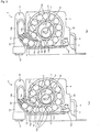
- Fig. 7 shows a pretensioner according to a fourth example of the embodiment of the present invention
- Fig. 7(a) being a schematic perspective view showing a blocking member used in the pretensioner according to the fourth example
- Fig. 7(b) being an enlarged fragmentary cross-sectional view similar to a part of Fig. 5(c) partially showing a state where the gas generator is mounted
- Fig. 7(c) being an enlarged fragmentary cross-sectional view of a portion VIIC in Fig. 7(b) .
- the side walls 25b, 25c of the blocking member 25 respectively include the blocking surfaces 25b 1 , 25c 1 on the outer side and the fitting surfaces 25b 2 , 25c 2 (see Fig. 5(a) ) on the inner side in the pretensioner 8 according to the second example
- the side walls 25b, 25c respectively include only the fitting surfaces 25b 2 , 25c 2 on the inner side in the pretensioner 8 according to the fourth example, as shown in Figs. 7(a) to 7(c) .
- the side walls 25b, 25c serve as fitting portions via which the blocking member 25 is to be supported by the case 14a.
- the side walls 25b, 25c are partially cut and the cut portion is outwardly bent so as to form blocking portions 25d, 25e.
- the blocking portions 25d, 25e are formed parallel or substantially parallel to the respectively corresponding side walls 25b, 25c.
- the respective outer surfaces of the blocking portions 25d, 25e serve as blocking surfaces 25d 1 , 25e 1 .
- the side walls 25b, 25c and the blocking portions 25d, 25e have the clipping function.
- the configuration of the remaining portions of the pretensioner 8 according to the fourth example is substantially the same as that of the second example.
- the blocking member 25 is removably fitted to the case 14a of the gas generator 14 such that the fitting surfaces 25b 2 , 25c 2 of the side walls 25b, 25c are elastically in contact with the planar surfaces 14b, 14c of the case 14a.
- the blocking surface 25d 1 of one of the blocking portions 25d, 25e (blocking portion 25d in this example) is separably disposed in contact with the planner inner surface 13a 2 of the gas generator mount 13, so as to block the discharge hole 13b.
- the case 14a expands owing to the pressure of the gas, so that the blocking surface 25d 1 of the blocking portion 25d is pressed against the inner surface 13a 2 of the gas generator mount 13. Accordingly, the blocking portion 25d effectively comes into close contact with the inner surface 13a 2 , so that the discharge hole 13b becomes more air-tightly blocked.
- the blocking portion 25d Upon pressing the blocking surface 25d 1 through the discharge hole 13b, as in the foregoing examples, with the pressing force F equal to or greater than the predetermined pressing force after the operation of the pretensioner 8 to thereby discharge the gas from the pipe 10, the blocking portion 25d is flexurally deformed so that the blocking surface 25d 1 is separated from the inner surface 13a 2 of the gas generator mount 13, as indicated by dash-dot-dot lines in Fig. 7(c) . Accordingly, the discharge hole 13b is opened and the gas inside of the pipe 10 and the gas generator mount 13 is outwardly discharged, and the pressure in the gas generator mount 13 and the pipe 10 returns to the atmospheric pressure.
- the blocking portion 25d may be flexurally deformed while causing the case 14a of the gas generator 14 to be concavely deformed.
- Providing the fitting portions 25b, 25c and the blocking portions 25d, 25e separately from each other as in the pretensioner 8 according to the fourth example enables the fitting portions to more effectively retain the blocking member 25, and allows the blocking portions 25d, 25e to more effectively block the discharge hole 13b.
- the operation and the advantageous effects of the pretensioner 8 according to the fourth example are substantially the same as those of the second example.
- the configuration of the remaining portions of the seatbelt retractor 3 including the pretensioner 8 according to the fourth example and the advantageous effects thereof, as well as the configuration of the remaining portions of the seatbelt unit 1 including the seatbelt retractor 3 according to the fourth example and the operation thereof, are substantially the same as those of the seatbelt retractor 3 and the seatbelt unit 1 according to the first example.
- Fig. 8 shows a pretensioner according to a fifth example of the embodiment of the present invention
- Fig. 8(a) being a schematic perspective view showing a blocking member used in the pretensioner according to the fifth example
- Fig. 8(b) being an enlarged fragmentary cross-sectional view similar to Fig. 7(b) partially showing a state where the gas generator is mounted
- Fig. 8(c) being an enlarged fragmentary cross-sectional view of a portion VIIIC in Fig. 8(b) .
- one of the blocking portions 25d, 25e according to the fourth example that is disposed so as to block the discharge hole 13b includes a blocking projection 25f formed so as to outwardly protrude, such that a portion thereof can intrude into the discharge hole 13b.
- the blocking projection 25f is formed in a semispherical or substantially semispherical shape.
- the configuration of the remaining portions of the pretensioner 8 according to the fifth example is substantially the same as that of the fourth example.
- the blocking projection 25f formed on one of the blocking portions intrudes into the discharge hole 13b and a portion of the blocking surface 25d 1 peripheral to the base portion of the blocking projection 25f comes into contact with the planner inner surface 13a 2 of the gas generator mount 13, so as to block the discharge hole 13b.
- the blocking surface 25d 1 of the blocking portion 25d is effectively brought into close contact with the inner surface 13a 2 by the gas pressure, so that the discharge hole 13b is more air-tightly blocked, as in the foregoing examples.
- the blocking projection 25f intruding into the discharge hole 13b further ensures the air-tight blocking effect of the discharge hole 13b.
- the blocking projection 25f is pressed through the discharge hole 13b with the pressing force F equal to or greater than the predetermined pressing force after the operation of the pretensioner 8 to thereby discharge the gas from the pipe 10, instead of the blocking surface 25d 1 as in the foregoing examples.
- the blocking portion 25d is flexurally deformed and the discharge hole 13b is opened.
- the configuration of the remaining portions of the seatbelt retractor 3 including the pretensioner 8 according to the fifth example and the advantageous effects thereof, as well as the configuration of the remaining portions of the seatbelt unit 1 including the seatbelt retractor 3 according to the fifth example and the operation thereof, are substantially the same as those of the seatbelt retractor 3 and the seatbelt unit 1 according to the first example.
- Fig. 9 shows a pretensioner according to a sixth example of the embodiment of the present invention
- Fig. 9(a) being a schematic perspective view showing a blocking member used in the pretensioner according to the sixth example
- Fig. 9(b) being an enlarged fragmentary cross-sectional view similar to Fig. 7(b) partially showing a state where the gas generator is mounted
- Fig. 9(c) being an enlarged fragmentary cross-sectional view of a portion IXC in Fig. 9(b) .
- the blocking member 25 includes the pair of side walls 25b, 25c serving as the fitting portion, and the blocking portion 25d, as in the pretensioner 8 according to the fifth example. While the pair of blocking portions 25d, 25e are provided in the fifth example, just the single blocking portion 25d is provided in the sixth example. However, the pair of blocking portions 25d, 25e may be provided in the sixth example. The following description is based on the assumption that only the blocking portion 25d is provided.
- the pair of side walls 25b, 25c are connected via the bottom portion 25a formed in a curved shape as in the third example shown in Fig. 6 , and have the clipping function.
- the pair of blocking portions 25d, 25e are formed so as to outwardly protrude from the respectively corresponding side walls 25b, 25c; in other words the pair of blocking portions 25d, 25e and the respectively corresponding side walls 25b, 25c are formed in different planes.
- the blocking portion 25d is formed on the same or substantially the same plane as the side wall 25b, in a direction orthogonal or substantially orthogonal to the curving direction of the blocking member 25.
- the blocking member 25 is removably fitted to the case 14a from a lateral direction as the blocking member of the third example, such that the pair of side walls 25b, 25c are oriented orthogonal to the longitudinal direction of the gas generator 14.
- the blocking projection 25f of the blocking portions 25d intrudes into the discharge hole 13b and a portion of the blocking surface 25d 1 peripheral to the base portion of the blocking projection 25f comes into contact with the planner inner surface 13a 2 of the gas generator mount 13, so as to block the discharge hole 13b.
- the respective outer surfaces of the side walls 25b, 25c also come into contact with the planar inner surface 13a 2 of the gas generator mount 13, in the sixth example.
- the respective outer surfaces of the side walls 25b, 25c may be formed so as to be spaced from the inner surface 13a 2 of the gas generator mount 13.
- the configuration of the remaining portions of the pretensioner 8 according to the sixth example is substantially the same as that of the fifth example.
- the blocking projection 25f is pressed through the discharge hole 13b with the pressing force F equal to or greater than the predetermined pressing force after the operation of the pretensioner 8 to thereby discharge the gas from the pipe 10, instead of the blocking surface 25d 1 as in the foregoing examples.
- the blocking portion 25d is flexurally deformed and the discharge hole 13b is opened.
- the side wall 25b is barely deformed.
- the configuration of the remaining portions of the seatbelt retractor 3 including the pretensioner 8 according to the sixth example and the advantageous effects thereof, as well as the configuration of the remaining portions of the seatbelt unit 1 including the seatbelt retractor 3 according to the sixth example and the operation thereof, are substantially the same as those of the seatbelt retractor 3 and the seatbelt unit 1 according to the first example.
- Fig. 10 shows a pretensioner according to a seventh example of the embodiment of the present invention
- Fig. 10(a) being a cross-sectional view similar to Fig. 4(c)
- Fig. 10(b) being a front view of a blocking member
- Fig. 10(c) being a cross-sectional view taken along a line XC-XC in Fig. 10(b) for explaining an operation
- Fig. 10(d) being an enlarged fragmentary cross-sectional view of a portion XD in Fig. 10(a)
- Fig. 10(e) being a front view showing a variation of the seventh example
- Fig. 10(f) being a right side view of Fig. 10(e) .
- the blocking member 25 according to the first example is formed of the thin plate attached to the case 14a
- the blocking member 25 of the pretensioner 8 according to the seventh example is formed in a pin shape including a disk-shaped head portion 25g and a shaft portion 25h formed projecting from the center of the head portion 25g so as to be fitted in the discharge hole 13b, as shown in Figs. 10(a) and 10(b) .
- the shaft portion 25h has a diameter substantially the same as that of the discharge hole 13b.
- the head portion 25g has an outer diameter larger than the diameter of the discharge hole 13b.
- the surface of the head portion 25g from which the shaft portion 25h is projecting serves as a blocking surface 25g 1 disposed in close contact with the inner surface 13a 2 of the gas generator mount 13 so as to block the discharge hole 13b.
- the head portion 25g includes a chamfered portion 25g 2 formed along the peripheral edge of the surface thereof opposite the blocking surface 25g 1 .
- the shaft portion 25h includes a predetermined number (in this example, four) of discharge grooves 25h 1 formed on the outer circumferential surface thereof so as to extend in an axial direction.
- the blocking member 25 is first attached to the gas generator mount 13 as shown in Fig. 10(a) . More specifically, the shaft portion 25h of the blocking member 25 is fitted in the discharge hole 13b and the blocking surface 25g 1 is brought into contact with the inner surface 13a 2 of the gas generator mount 13. With the blocking member 25 thus fitted, the gas generator 14 is then inserted in the gas generator mount 13 from the left in Fig. 10(a) to be fitted therein.
- the gas generator 14 can be relatively smoothly fitted because of an interaction between a rounded portion 14e formed on the gas injecting end portion of the case 14a of the gas generator 14 and the chamfered portion 25g 2 of the head portion 25g.
- the configuration of the remaining portions of the pretensioner 8 according to the seventh example is substantially the same as that of the first example.
- the blocking surface 25g 1 of the blocking member 25 is brought into contact with the planar inner surface 13a 2 of the gas generator mount 13, so as to block the discharge hole 13b.
- the blocking surface 25g 1 of the blocking member 25 is effectively brought into close contact with the inner surface 13a 2 of the gas generator mount 13, so that the blocking member 25 more air-tightly blocks the discharge hole 13b.
- the shaft portion 25h is pressed through the discharge hole 13b with the pressing force F equal to or greater than the predetermined pressing force, as shown in Fig. 10(d) .
- the blocking member 25 is displaced while concavely deforming the case 14a so as to separate the blocking surface 25g 1 from the inner surface 13a 2 , and the discharge hole 13b is opened through the discharge grooves 25h 1 .
- the operation and the advantageous effects of the pretensioner 8 according to the seventh example are substantially the same as those of the first example.
- the configuration of the remaining portions of the seatbelt retractor 3 including the pretensioner 8 according to the seventh example and the advantageous effects thereof, as well as the configuration of the remaining portions of the seatbelt unit 1 including the seatbelt retractor 3 according to the seventh example and the operation thereof, are substantially the same as those of the seatbelt retractor 3 and the seatbelt unit 1 according to the first example.
- the shaft portion 25h may be formed in a stepped shape including a major diameter portion 25h 2 having an outer diameter substantially the same as the diameter of the discharge hole 13b and a minor diameter portion 25h 3 smaller in diameter than the major diameter portion 25h 2 .
- a major diameter portion 25h 2 having an outer diameter substantially the same as the diameter of the discharge hole 13b
- a minor diameter portion 25h 3 smaller in diameter than the major diameter portion 25h 2 .
- the blocking member 25 When the gas is to be discharged, the blocking member 25 is pressed with the pressing force F equal to or greater than the predetermined pressing force until at least the major diameter portion 25h 2 becomes disengaged from the discharge hole 13b, so that the gas can flow out through the gap between the outer circumferential surface of the minor diameter portion 25h 3 and the inner circumferential surface of the discharge hole 13b. In this case, therefore, it is not necessary to form the discharge groove 25h 1 on the shaft portion 25h.
- the shaft portion 25h may be solely formed of the major diameter portion 25h 2 , in other words in a shorter axial length than the shaft portion 25h shown in Figs. 10(a) to 10(d) .
- the shaft portion 25h when the blocking member 25 is pressed with the pressing force F equal to or greater than the predetermined pressing force the shaft portion 25h is entirely removed from the discharge hole 13b so as to open the discharge hole 13b.
- the shaft portion 25h may be solely formed of the minor diameter portion 25h 3 , instead of the stepped shape.
- the pretensioner and the seatbelt retractor according to the present invention are in no way limited to the foregoing examples, but various modifications may be made.
- the pipe 10 and the gas generator mount 13 are formed of a single material such that the base end portion 10b of the pipe 10 is formed as the gas generator mount 13 in the foregoing examples, the pipe 10 and the gas generator mount 13 may be separately formed and then air-tightly and integrally coupled.
- the spool driving mechanism is not limited to the combination of the plurality of force transmission members 12, the link gear 15, and the pinion 19 according to the foregoing examples, but any mechanisms including a rack and pinion mechanism may be employed, as long as the mechanism allows the spool to rotate in the seatbelt retracting direction with the pressure of the gas generated in the pipe 10 by the gas generator 14. Further, the discharge hole 13b may be located in the pipe 10 at a position between the gas generator 14 and the force transmission member 12, instead of in the gas generator mount 13.
- the present invention is applicable to any pretensioner within the scope defined in the appended claims, provided that the pretensioner includes a gas generator that generates a gas in an emergency case.
- the pretensioner, the seatbelt retractor, and the seatbelt unit according to the present invention are suitably applicable to a pretensioner that includes a gas generator to be activated so as to generates a gas at an initial stage of an emergency case, a seatbelt retractor configured to retract the seatbelt in cooperation with the pretensioner, and a seatbelt unit configured to restrain an occupant by using the seatbelt retractor in the emergency case.
Landscapes
- Engineering & Computer Science (AREA)
- Mechanical Engineering (AREA)
- Automotive Seat Belt Assembly (AREA)
Abstract
Description
- Embodiments described herein relate to a pretensioner, a seatbelt retractor, and a seatbelt unit that activates the seatbelt retractor.
- Various seatbelt retractors that include a pretensioner have thus far been developed for use in a seatbelt unit provided in a vehicle such as an automobile. The pretensioner is configured so as to rotate a spool of the seatbelt retractor in a direction to retract the seatbelt with a gas generated by a gas generator at an initial stage of an emergency case, to thereby take up the seatbelt around the spool. This action quickly removes slack of the seatbelt and gives higher tension to the seatbelt, thus increasing the restraining force of the seatbelt with respect to the occupant.
- An example of conventional pretensioners includes a plurality of force transmission members composed of balls accommodated in a pipe, and the force transmission members are made to move by the pressure of the gas generated by the gas generator inside of the pipe, so as to be pressed against a plurality of pressure-receiving portions formed of a lever of a link gear, so that the spool is made to rotate in the direction to retract the seatbelt by the rotation of the link gear (for example, see
JP-A-2001-63520 - In the pretensioner according to
JP-A-2001-63520 - Recently, usable parts of vehicles that include a pretensioner that has been activated in an emergency case are required to be recycled. However, in general, a considerable gas pressure resides in the pipe after the pretensioner is activated. Such a residual gas pressure in the pipe makes it difficult to demolish the vehicle to recycle the usable parts. Accordingly, it is necessary to discharge the gas inside of the pipe before demolishing the vehicle.
- A technique of discharging the gas out of the pipe is disclosed in
JP-A-2001-63520 JP-A-2001-63520 JP-A-2001-63520 - The present invention provides a pretensioner as defined in
claim 1. The dependent claims define preferred embodiments of the invention. One of illustrative aspects of the present invention is to provide a pretensioner from which a gas residing in a pipe can be easily discharged out of the pipe after the operation of the pretensioner is finished, a seatbelt retractor with the pretensioner, and a seatbelt unit including the seatbelt retractor. - According to one or more illustrative aspects of the present invention, there is provided a pretensioner. The pretensioner includes: a pipe; a gas generator that generates a gas in the pipe in an emergency case; a gas generator mount on which the gas generator is mounted; a spool driving mechanism that rotates a spool in a direction to retract a seatbelt by the gas generated by the gas generator in the emergency case; a discharge hole formed in the pipe so as to allow communication between inside and outside of the pipe; and a blocking member configured to block the discharge hole from inside of the pipe, the blocking member being configured to open the discharge hole when the blocking member is pressed from outside of the pipe with a pressing force equal to or greater than a given pressing force.
- Other aspects and advantages of the present invention will be apparent from the following description, the drawings and the claims.
- The pretensioner configured as above according to the present invention includes the blocking member that blocks the discharge hole of the pipe from inside thereof and opens the discharge hole upon being moved by a pressing force greater than the predetermined pressing force from outside of the pipe. Such a configuration allows, the gas inside of the pipe to be easily discharged outwardly, simply by pressing the blocking member thereby opening the discharge hole, after the operation of the pretensioner.
- In particular, the generated gas serves to press the blocking member in the direction to more air-tightly block the discharge hole, and hence the blocking member can more effectively block the discharge hole during the operation of the pretensioner. Such an arrangement suppresses the pressure loss of the generated gas and allows the occupants to be more effectively restrained.
- Providing the fitting portion and the blocking portion on the blocking member separately from each other enables the fitting portion to more effectively support the blocking member, and allows the blocking portion to more effectively block the discharge hole. In addition, forming the blocking projection that intrudes into the discharge hole on the blocking portion allows the discharge hole to be more air-tightly blocked.
- Further, the seatbelt retractor and the seatbelt unit according to the present invention include the pretensioner according to the present invention. Accordingly, the gas inside of the gas generator mount and the pipe can be easily discharged outwardly after the operation of the pretensioner. Consequently, the vehicle such as an automobile including the pretensioner that has been activated can be easily demolished to recycle the parts used in the vehicle.
-
-
Fig. 1 is a schematic perspective view showing a seatbelt unit including a seatbelt retractor with a pretensioner according to a first example of an embodiment of the present invention; -
Fig. 2 is a partially cut away side view of the seatbelt retractor and the pretensioner according to the first example shown inFig. 1 ; -
Fig. 3(a) is a partially cut away side view of the pretensioner according to the first example shown inFig. 1 during an operation; -
Fig. 3(b) showing a state of the pretensioner after the operation; -
Fig. 4(a) is a schematic perspective view showing a gas generator and a blocking member according to the first example; -
Fig. 4(b) is a perspective view showing a gas generator mount according to the first example; -
Fig. 4(c) is a cross-sectional view taken along a line IVC-IVC inFig. 4(b) ; -
Fig. 4(d) is an enlarged fragmentary cross-sectional view of a portion IVD inFig. 4(c) . -
Fig. 5(a) is a schematic perspective view showing a gas generator and a blocking member according to a second example of the embodiment; -
Fig. 5(b) is a perspective view showing a gas generator mount; -
Fig. 5(c) is a cross-sectional view taken along a line VC-VC inFig. 5(b) ; -
Fig. 6(a) is a schematic perspective view showing a gas generator and a blocking member according to a third example of the embodiment; -
Fig. 6(b) is a perspective view showing a gas generator mount; -
Fig. 6(c) is a cross-sectional view taken along a line VIC-VIC inFig. 6(b) ; -
Fig. 7(a) is a schematic perspective view showing a blocking member used in the pretensioner according to a fourth example of the embodiment; -
Fig. 7(b) is an enlarged fragmentary cross-sectional view similar to a part ofFig. 5(c) partially showing a state where the gas generator is mounted; -
Fig. 7(c) is an enlarged fragmentary cross-sectional view of a portion VIIC inFig. 7(b) ; -
Fig. 8(a) is a schematic perspective view showing a blocking member used in the pretensioner according to a fifth example of the embodiment; -
Fig. 8(b) is an enlarged fragmentary cross-sectional view similar toFig. 7(b) partially showing a state where the gas generator is mounted; -
Fig. 8(c) is an enlarged fragmentary cross-sectional view of a portion VIIIC inFig. 8(b) ; -
Fig. 9(a) is a schematic perspective view showing a blocking member used in the pretensioner according to a sixth example of the embodiment; -
Fig. 9(b) is an enlarged fragmentary cross-sectional view similar toFig. 7(b) partially showing a state where the gas generator is mounted; -
Fig. 9(c) is an enlarged fragmentary cross-sectional view of a portion IXC inFig. 9(b) ; -
Fig. 10(a) is a cross-sectional view similar toFig. 4(c) in the pretensioner according to a seventh example of the embodiment; -
Fig. 10(b) being a front view of a blocking member; -
Fig. 10(c) is a cross-sectional view taken along a line XC-XC inFig. 10(b) for explaining an operation; -
Fig. 10(d) is an enlarged fragmentary cross-sectional view of a portion XD inFig. 10(a) ; -
Fig. 10(e) is a front view showing a variation of the seventh example; and -
Fig. 10(f) is a right side view ofFig. 10(e) . - Hereafter, exemplary embodiments of the present invention will be now described with reference to the drawings.
Fig. 1 is a schematic perspective view showing a seatbelt unit including a seatbelt retractor with a pretensioner according to a first example of the embodiment of the present invention. - As shown in
Fig. 1 , theseatbelt unit 1 according to the first example is basically the same as a conventionally known three-point seatbelt unit. InFig. 1 , areference numeral 1 designates the seatbelt unit, 2 designates a vehicle seat, 3 designates a seatbelt retractor located close to the vehicle seat 2, 4 designates a seatbelt that can be withdrawably retracted in theseatbelt retractor 3 and including a belt anchor 4a attached to a leading end thereof via which the seatbelt 4 is fixed to the vehicle floor or thevehicle seat 2, 5 designates a guide anchor that guides the seatbelt 4 withdrawn from theseatbelt retractor 3 to a shoulder of the occupant, 6 designates a tongue slidably supported by the seatbelt 4 extending from theguide anchor tongue 6 is to be removably inserted for connection.
The fastening and releasing operation of the seatbelt 4 of theseatbelt unit 1 is also the same as that of the conventionally known seatbelt unit. - The
seatbelt retractor 3 according to the first example may be either a conventionally known emergency locking seatbelt retractor (ELR) or a conventionally known automatic locking seatbelt retractor (ALR). Theseatbelt retractor 3 includes a pretensioner. The pretensioner is activated, as a conventionally known pretensioner is, in an emergency case such as collision in which a deceleration far greater than that experienced during a normal driving has been applied to a vehicle, so as to rotate a spool (not shown) of theseatbelt retractor 3 in a direction to retract the seatbelt (hereinafter, seatbelt retracting direction) to thereby take up the seatbelt 4 by a predetermined length thus increasing the restraining force of the seatbelt with respect to the occupant. -
Fig. 2 is a partially cut away side view of the seatbelt retractor including the pretensioner according to the first example shown inFig. 1 .
As shown inFig. 2 , thepretensioner 8 according to the first example is supported by aframe 9 of theseatbelt retractor 3. Theframe 9 includes abase portion 9a located on the side of the vehicle chamber (left side inFig. 2 ) so as to be attached to the vehicle body, and a pair ofside walls base portion 9a. - The
pretensioner 8 includes apipe 10, and aguide member 11 is provided at aleading end portion 10a of thepipe 10. Theleading end portion 10a of thepipe 10 and theguide member 11 are attached to apipe mount 23 fixed to theside wall 9b with a fixture such as a bolt. Acutaway portion 10c is formed on theleading end portion 10a of thepipe 10, so as to allow communication between inside and outside of thepipe 10 and extending in a longitudinal direction of thepipe 10. - The
pipe 10 stores therein a plurality ofballs 12a made of a metal such as iron or aluminum, and a plurality offorce transmission members 12 constituted of a piston (not shown) that presses theballs 12a with a gas pressure, theballs 12a and theforce transmission members 12 being movable and disposed in contact with each other. Abase end portion 10b of thepipe 10 is formed in a larger diameter than the force transmission member storage portion of thepipe 10, and constitutes agas generator mount 13. Agas generator 14 is mounted on thegas generator mount 13. - The
pretensioner 8 includes a case body (not shown) attached to theside wall 9b of theframe 9. The case body includes alink gear 15 mounted so as to rotate and to move to the right inFig. 2 . Thelink gear 15 includes a plurality ofinner teeth 15a formed on an inner circumferential surface thereof. Thelink gear 15 is formed so as to partially intrude into thepipe 10 through thecutaway portion 10c of thepipe 10. - The
link gear 15 includes a generallyarcuate stopper 16 disposed in contact with a first (leading) one of theballs 12a in a normal state (while thepretensioner 8 is not activated) and having an outer peripheral edge of a predetermined circumferential length (corresponding to the pressure-receiving portion according to the present invention), and a plurality (in the first example, six) of generally triangular levers 17 (corresponding to the pressure-receiving portion according to the present invention), thestopper 16 and thelevers 17 being formed so as to project from an outer circumferential surface of thelink gear 15. Thestopper 16 and all of thelevers 17 can intrude into thepipe 10 through thecutaway portion 10c. - A
pinion 19 is attached to arotary shaft 18 of a locking base (not shown) of theseatbelt retractor 3, so as to rotate interlocked with the rotary shaft 18 (here, thepinion 19 may be attached to a rotary shaft of the spool (not shown) of theseatbelt retractor 3, so as to rotate interlocked with the rotary shaft). The locking base is employed in the conventionally known ELR and ALR. The locking base rotates, in the normal state, interlocked with the spool of theseatbelt retractor 3 that takes up the seatbelt 4, and is locked by a lock mechanism to be activated in the emergency case to thereby inhibit the rotation of the spool in the direction to withdraw the seatbelt. The ELR that employs the pretensioner including the plurality of balls and the locking base can be found, for example, in Japanese Unexamined Patent Application Publication No.2001-233172 2001-233172 - The
pinion 19 includes a plurality ofouter teeth 19a. Theouter teeth 19a of thepinion 19 are to be engaged with theinner teeth 15a of thelink gear 15. Once thepretensioner 8 is activated, theballs 12a press from above thestopper 16 and thelevers 17 intruding in thepipe 10 through thecutaway portion 10c thereof, to thereby apply to thelink gear 15 a rotational driving force in the seatbelt retracting direction (counterclockwise inFig. 2 ) as well as a linear displacement force toward thepinion 19. - In a normal state, the
link gear 15 is retained byshear pins 20 at a standby position shown inFig. 2 . While thelink gear 15 is at the standby position theinner teeth 15a are not engaged with theouter teeth 19a, but spaced therefrom. In an emergency case, thepretensioner 8 is activated so that a pressing force originating from the pressure of the gas generated by thegas generator 14 is applied to theforce transmission members 12, and theforce transmission members 12 apply a rotational driving force and a linear displacement force to thelink gear 15. Resultantly the shear pins 20 undergo a shear failure and thelink gear 15 is moved to an operational position shown inFig. 3(a) . When thelink gear 15 comes to the operational position, theinner teeth 15a are engaged with theouter teeth 19a. Accordingly, thelink gear 15 and the pinion 19 (in other words, spool) are rotationally coupled, such that therotary shaft 18, hence the spool, is caused to rotate in the seatbelt retracting direction through the plurality offorce transmission members 12, thelink gear 15, and thepinion 19 by the pressing force originating from the pressure of the gas generated by thegas generator 14. Thus, the plurality offorce transmission members 12, thelink gear 15, and thepinion 19 constitute the spool driving mechanism according to the present invention. - The
gas generator 14 includes acase 14a of a stepped cylindrical shape, as shown inFig. 4(a) . Aplanar surface 14b is formed on an outer circumferential surface of an end portion of thecase 14a on a gas-injecting side (lower end portion inFig. 4(a) ). An inner circumferential surface of thecase 14a opposite theplanar surface 14b may be similarly formed in a planar surface, or in a cylindrical shape. - As shown in
Fig. 4(b) , thegas generator mount 13 includes aplanar portion 13a. Anouter surface 13a1 and aninner surface 13a2 of theplanar portion 10 are both formed in a planar surface as shown inFigs. 4(c) and 4(d) . Theplanar portion 13a includes adischarge hole 13b that allows communication between outside and inside of the gas generator mount 13 (in other words, pipe 10). When thegas generator 14 is fitted in thegas generator mount 13, at least a part of theplanar surface 14b of thecase 14a of thegas generator 14 and at least a part of the planarinner surface 13a2 of thegas generator mount 13 including thedischarge hole 13b are disposed so as to oppose each other, as indicated by dash-dot-dot lines inFig. 4(b) . - As shown in
Figs. 4(a) to 4(d) , a blockingmember 25 formed of a metal such as iron or a resin in a thin flat plate of a predetermined shape (in this example, rectangular) is joined to theplanar surface 14b of thecase 14a of thegas generator 14, via an adhesive or the like (indicated by dash-dot-dot lines inFigs. 4(a) and 4(b) ). The blockingmember 25 is located so as to oppose the entirety of thedischarge hole 13b when thegas generator 14 is fitted in thegas generator mount 13. Accordingly, when thegas generator 14 is fitted in thegas generator mount 13 as shown inFigs. 4(b) and 4(c) , the outer surface of the blockingmember 25 is brought into contact with theinner surface 13a2 of thegas generator mount 13 of thepipe 10, so as to block thedischarge hole 13b from inside of the gas generator mount 13 (in other words, from inside of the pipe 10). Thus, the outer surface of the blockingmember 25 constitutes a blockingsurface 25b1 that blocks thedischarge hole 13b. - On the other hand, when the blocking
member 25 is pressed, while being disposed so as to block thedischarge hole 13b, by a pressing device (not shown) such as a tool from outside of the gas generator mount 13 (outside of the pipe 10) through thedischarge hole 13b, with a pressing force F equal to or greater than a predetermined pressing force as shown inFig. 4(d) , thedischarge hole 13b is opened. To be more detailed, a predetermined region of thecase 14a of thegas generator 14 including the portion where the blockingmember 25 is attached is concavely deformed upon being pressed with the pressing force F equal to or greater than the predetermined pressing force, and the blockingmember 25 is displaced while being deformed, so that the blockingsurface 25b1 is separated from theinner surface 13a2 of thegas generator mount 13. Thus, thedischarge hole 13b is opened so as to allow communication between outside and inside of thedischarge hole 13b. - An operation of the
pretensioner 8 configured as above according to the first example will now be described.
The operation of thepretensioner 8 according to the first example is basically the same as that of the conventional pretensioner that employs the plurality of ball, up to the stage where the spool of theseatbelt retractor 3 is caused to rotate in the seatbelt retracting direction in an emergency case. - While the
pretensioner 8 remains unactivated, thelink gear 15 is retained at the standby position as shown inFig. 2 . Accordingly, theinner teeth 15a of thelink gear 15 are kept from being engaged with theouter teeth 19a of thepinion 19. Also, thefirst ball 12a is retained in contact with alateral face 16a of thestopper 16 on an upstream side in the rotating direction of the link gear 15 (counterclockwise inFig. 2 , i.e., the seatbelt retracting direction). Thesubsequent balls 12a are sequentially in contact with the adjacent ones. In such a state, thegas generator 14 does not generate the gas and theballs 12a are substantially kept from applying a pressing force to thestopper 16 on thelink gear 15. In addition, thedischarge hole 13b is air-tightly blocked by the blockingmember 25. - Once an emergency case has occurred, the
pretensioner 8 is activated. More specifically, thegas generator 14 is activated so as to generate the gas, and thecase 14a of thegas generator 14 expands outwardly owing to the pressure of the generated gas. The expansion of thecase 14a brings the blockingsurface 25b1 of the blockingmember 25 into firm and close contact with theinner surface 13a2 of thegas generator mount 13. Accordingly, thedischarge hole 13b becomes more air-tightly blocked by the blockingmember 25. - The gas generated by the
gas generator 14 opens up the gas injectingend face 14d of thecase 14a and intrudes into thegas generator mount 13. At this stage, since thedischarge hole 13b is air-tightly blocked by the blockingmember 25, the gas inside of thegas generator mount 13 and thepipe 10 is inhibited from leaking out of thegas generator mount 13 and thepipe 10, and hence gas pressure loss is barely incurred. - The gas in the
gas generator mount 13 further proceeds into thepipe 10. The gas that has intruded into thepipe 10 applies a great pressing force to theballs 12a through a piston 24 (seeFig. 3(a) ). Then thestopper 16 of thelink gear 15 is pressed by theballs 12a, so that the shear pins 20 undergo a shear failure. Accordingly, thelink gear 15 is displaced to the right inFig. 2 and caused to rotate counterclockwise, by the pressing force applied through theballs 12a. Theinner teeth 15a of thelink gear 15 are then engaged with theouter teeth 19a of thepinion 19 as shown inFig. 3(a) , so that thepinion 19 starts to rotate in the same direction as thelink gear 15. Thus, therotary shaft 18 hence the spool starts to rotate in the seatbelt retracting direction, so that the seatbelt 4 worn by the occupant starts to be retracted. - Thereafter, the
subsequent balls 12a sequentially press thelevers 17 as shown inFig. 3(a) , which makes thelink gear 15 and thepinion 19 rotate together in the seatbelt retracting direction (counterclockwise inFig. 3(a) ). Accordingly, the seatbelt 4 is taken up around the spool by a longer distance. - When a
subsequent ball 12a starts to press thelever 17, the pressing force of the precedingball 12 that pressed thelever 17 earlier becomes substantially ineffective. Theballs 12 that have lost the pressing force move with the rotation of thelink gear 15 along aguide groove 21. Then thefirst ball 12a comes into contact with astopper 22 of the case body as shown inFig. 3(a) . At this stage, alateral face 16b of thestopper 16 of thelink gear 15 on a downstream side in the rotating direction of the link gear is not in contact with any of the opposingballs 12a. - When the
first ball 12a comes into contact with thestopper 22, thestopper 22 is deformed by the pressing force of thefirst ball 12a as shown inFig. 3(b) , and thelink gear 15 further rotates counterclockwise. Such deformation of thestopper 22 absorbs a part of the kinetic energy of therespective balls 12a. The additional counterclockwise rotation of thelink gear 15 brings the outerperipheral edge 16c of thestopper 16 of thelink gear 15 into contact with the opposingball 12a as shown inFig. 3(b) , so that theball 12a is detained between the outerperipheral edge 16c of thestopper 16 and the innercircumferential surface 10d of thepipe 10 opposite thecutaway portion 10c. Accordingly thelink gear 15 stops rotating. Therefore thepinion 19 and the spool also stop rotating and the spool finishes taking up the seatbelt, and thus the operation of thepretensioner 8 is finished. The retracting action of the seatbelt 4 by thepretensioner 8 increases the restraining force of the seatbelt 4 with respect to the occupant. - At this stage, the volume of the space inside of the
pipe 10 directly communicating with the inside of the gas generator mount 13 (space unoccupied with theballs 12a) is increased, and hence a residual gas pressure is present in thegas generator mount 13 and thepipe 10, although the residual gas pressure is somewhat lower than the peak pressure of the generated gas. Also, thedischarge hole 13b remains air-tightly blocked by the blockingmember 25 even after the operation of thepretensioner 8 is finished. - To discharge the gas from the
gas generator mount 13 and thepipe 10 at a certain timing after thepretensioner 8 finishes the operation, the blockingmember 25 is pressed with the pressing force F equal to or greater than the predetermined pressing force, as shown inFig. 4(d) . Then the blockingmember 25 is deformed and displaced while causing deformation of the predetermined region of thegas generator mount 13 including the portion where the blockingmember 25 is attached, thus to be separated from theinner surface 13a2 of thegas generator mount 13. Accordingly, thedischarge hole 13b is opened and the gas inside of thepipe 10 flows out through thedischarge hole 13b as indicated by an arrow α inFig. 4(d) , and the pressure in thegas generator mount 13 and thepipe 10 substantially returns to the atmospheric pressure. Here, althoughFig. 4(d) illustrates such that the gas flows through the gap between theplanar surface 14b, which is the outer surface of thecase 14a on which the blockingmember 25 is provided, and theinner surface 13a2 of thegas generator mount 13, actually the gas is discharged also through a gap between another portion of the outer surface of thecase 14a and another portion of the inner surface of thegas generator mount 13. - The configuration of the remaining portions of the
pretensioner 8 according to the first example, as well as the operation thereof, is substantially the same as those of the conventional pretensioner including the plurality of balls. Likewise, the configuration of the remaining portions of theseatbelt retractor 3 according to the first example, as well as the operation thereof, is substantially the same as those of the conventional ELR or ALR. - In the
pretensioner 8 according to the first example, thegas generator mount 13 includes thedischarge hole 13b, which is normally blocked by the blockingmember 25 from inside of thegas generator mount 13. Thedischarge hole 13b can be opened after the operation of thepretensioner 8 is finished, by pressing the blockingmember 25 from outside of thegas generator mount 13 through thedischarge hole 13b with the pressing force F equal to or greater than the predetermined pressing force. Accordingly, the gas in thegas generator mount 13 and thepipe 10 can be easily discharged after the operation of thepretensioner 8 is finished, simply by pressing the blockingmember 25 thereby opening thedischarge hole 13b. - In particular, the generated gas serves to press the blocking
member 25 in the direction to more firmly block thedischarge hole 13b, and hence the blockingmember 25 can more effectively block thedischarge hole 13b during the operation of thepretensioner 8. Such an arrangement suppresses the pressure loss of the generated gas and allows the occupants to be more effectively restrained. - The
seatbelt retractor 3 and theseatbelt unit 1 according to the first example allow the gas inside of thegas generator mount 13 and thepipe 10 to be easily discharged after the operation of thepretensioner 8, thereby enabling the vehicle such as an automobile including thepretensioner 8 that has been activated to be easily demolished so as to recycle the parts used in the vehicle. -
Fig. 5 shows a pretensioner according to a second example of the embodiment of the present invention,Fig. 5(a) being a schematic perspective view showing a gas generator and a blocking member,Fig. 5(b) being a perspective view showing a gas generator mount, andFig. 5(c) being a cross-sectional view taken along a line VC-VC inFig. 5(b) . In the subsequent description of examples of the embodiment, the same constituents will be given the same numeral, and detailed description thereof will not be repeated. - While the
case 14a of thegas generator 14 includes a singleplanar surface 14b formed on the outer surface thereof in thepretensioner 8 according to the first example, a pair ofplanar surfaces pretensioner 8 according to the second example, as shown inFigs. 5(a) to 5(c) . In this case, the pair ofplanar surfaces cylindrical case 14a. In addition, the region of thecase 14a where the pair ofplanar surfaces - Although the blocking
member 25 of thepretensioner 8 according to the first example is formed of a thin plate, the blockingmember 25 of thepretensioner 8 according to the second example is formed of a flat and thin strip-shaped plate as shown inFigs. 5(a) and 5(c) . In this case, the blockingmember 25 is formed by bending the respective end portions of the strip-shaped plate, generally into a C-shape or U-shape in a side view, and includes abottom portion 25a at the central portion and a pair ofside walls bottom portion 25a. The pair ofside walls member 25 has a clipping function. The blockingmember 25 is disposed such that thebottom portion 25a is in contact with the gas injectingend face 14d (lower end face inFig. 4(a) ) of thecase 14a, and theside walls planar surfaces case 14a respectively, because of the clipping function. Thus, the blockingmember 25 is removably fitted to thecase 14a. Accordingly, the respective outer surfaces of theside walls surfaces discharge hole 13b. The respective inner surfaces of theside walls fitting surfaces planar surfaces case 14a. Although the blockingsurface 25b1 of theside wall 25b blocks thedischarge hole 13b in the second example, the blockingsurface 25c1 of the opposingside wall 25c may be disposed so as to block thedischarge hole 13b. - When the
gas generator 14 is fitted in thegas generator mount 13 with the blockingmember 25 fitted to thecase 14a, one of theside walls side wall 25b in this example) of the blockingmember 25 is disposed in contact with the plannerinner surface 13a2 of thegas generator mount 13, so as to block thedischarge hole 13b. In this case, since theside walls member 25 have the clipping function and are held between the outer surface of thecase 14a of thegas generator 14 and theinner surface 13a2 of thegas generator mount 13, the blockingmember 25 can be kept from coming off from thecase 14a of thegas generator 14 in a normal state.
The configuration of the remaining portions of thepretensioner 8 according to the second example is the same as that of the first example. - In the
pretensioner 8 configured as above according to the second example, thecase 14a of thegas generator 14 expands outwardly owing to the pressure of the gas generated by thegas generator 14 once thepretensioner 8 is activated, so that theside wall 25b effectively comes into close contact with theinner surface 13a2 of thegas generator mount 13. Accordingly, thedischarge hole 13b becomes more air-tightly blocked by theside wall 25b, and the gas is suppressed from leaking through thedischarge hole 13b, resulting in reduced gas pressure loss. - Upon pressing the
side wall 25b through thedischarge hole 13b, as in the first example, with the pressing force F equal to or greater than the predetermined pressing force after the operation of thepretensioner 8 to thereby discharge the gas from thepipe 10 and thegas generator mount 13, thecase 14a is concavely deformed and theside wall 25b is flexurally deformed, so that theside wall 25b is separated from theinner surface 13a2 of thegas generator mount 13. Accordingly, thedischarge hole 13b is opened and the gas inside of thepipe 10 is outwardly discharged, and the pressure in thegas generator mount 13 and thepipe 10 returns to the atmospheric pressure.
The operations of other aspects of thepretensioner 8 according to the second example are the same as those of the first example. The second example offers substantially the same advantageous effects as those offered by the first example. - Further, the configuration of the remaining portions of the
seatbelt retractor 3 including thepretensioner 8 according to the second example and the advantageous effects thereof, as well as the configuration of the remaining portions of theseatbelt unit 1 including theseatbelt retractor 3 according to the second example and the operation thereof, are substantially the same as those of theseatbelt retractor 3 and theseatbelt unit 1 according to the first example. -
Fig. 6 shows a pretensioner according to a third example of the embodiment of the present invention,Fig. 6(a) being a schematic perspective view showing a gas generator and a blocking member,Fig. 6(b) being a perspective view showing a gas generator mount, andFig. 6(c) being a cross-sectional view taken along a line VIC-VIC inFig. 6(b) . - While the blocking
member 25 of thepretensioner 8 according to the second example is formed by bending the respective end portions of the strip-shaped plate, generally into a C-shape or U-shape in a side view, the blockingmember 25 of thepretensioner 8 according to the third example is formed by bending thecentral bottom portion 25a of the blockingmember 25 in a curved shape, generally into a C-shape (or U-shape) in a side view as shown inFigs. 6(a) to 6(c) . Therespective side walls member 25 according to the third example also have the clipping function. As shown inFig. 6(a) , the blockingmember 25 is removably and elastically fitted to thecase 14a from a lateral direction. In this state, the inner surface of thecurved bottom portion 25a comes into contract with the arcuate outer circumferential surface of thecase 14a.
The operation and the advantageous effects of thepretensioner 8 according to the third example are substantially the same as those of the second example. - Further, the configuration of the remaining portions of the
seatbelt retractor 3 including thepretensioner 8 according to the third example and the advantageous effects thereof, as well as the configuration of the remaining portions of theseatbelt unit 1 including theseatbelt retractor 3 according to the third example and the operation thereof, are substantially the same as those of theseatbelt retractor 3 and theseatbelt unit 1 according to the first example. -
Fig. 7 shows a pretensioner according to a fourth example of the embodiment of the present invention,Fig. 7(a) being a schematic perspective view showing a blocking member used in the pretensioner according to the fourth example,Fig. 7(b) being an enlarged fragmentary cross-sectional view similar to a part ofFig. 5(c) partially showing a state where the gas generator is mounted, andFig. 7(c) being an enlarged fragmentary cross-sectional view of a portion VIIC inFig. 7(b) . - While the
side walls member 25 respectively include the blocking surfaces 25b1, 25c1 on the outer side and thefitting surfaces Fig. 5(a) ) on the inner side in thepretensioner 8 according to the second example, theside walls fitting surfaces pretensioner 8 according to the fourth example, as shown inFigs. 7(a) to 7(c) . In other words, theside walls member 25 is to be supported by thecase 14a. - Further, in the
pretensioner 8 according to the fourth example, theside walls portions portions side walls portions surfaces member 25 according to the fourth example also, theside walls portions
The configuration of the remaining portions of thepretensioner 8 according to the fourth example is substantially the same as that of the second example. - The blocking
member 25 is removably fitted to thecase 14a of thegas generator 14 such that thefitting surfaces side walls planar surfaces case 14a. When thegas generator 14 is fitted in thegas generator mount 13, the blockingsurface 25d1 of one of the blockingportions portion 25d in this example) is separably disposed in contact with the plannerinner surface 13a2 of thegas generator mount 13, so as to block thedischarge hole 13b. - When the
gas generator 14 generates the gas in an emergency case, thecase 14a expands owing to the pressure of the gas, so that the blockingsurface 25d1 of the blockingportion 25d is pressed against theinner surface 13a2 of thegas generator mount 13. Accordingly, the blockingportion 25d effectively comes into close contact with theinner surface 13a2, so that thedischarge hole 13b becomes more air-tightly blocked. - Upon pressing the blocking
surface 25d1 through thedischarge hole 13b, as in the foregoing examples, with the pressing force F equal to or greater than the predetermined pressing force after the operation of thepretensioner 8 to thereby discharge the gas from thepipe 10, the blockingportion 25d is flexurally deformed so that the blockingsurface 25d1 is separated from theinner surface 13a2 of thegas generator mount 13, as indicated by dash-dot-dot lines inFig. 7(c) . Accordingly, thedischarge hole 13b is opened and the gas inside of thepipe 10 and thegas generator mount 13 is outwardly discharged, and the pressure in thegas generator mount 13 and thepipe 10 returns to the atmospheric pressure. Here, the blockingportion 25d may be flexurally deformed while causing thecase 14a of thegas generator 14 to be concavely deformed. - Providing the
fitting portions portions pretensioner 8 according to the fourth example enables the fitting portions to more effectively retain the blockingmember 25, and allows the blockingportions discharge hole 13b.
The operation and the advantageous effects of thepretensioner 8 according to the fourth example are substantially the same as those of the second example. - Further, the configuration of the remaining portions of the
seatbelt retractor 3 including thepretensioner 8 according to the fourth example and the advantageous effects thereof, as well as the configuration of the remaining portions of theseatbelt unit 1 including theseatbelt retractor 3 according to the fourth example and the operation thereof, are substantially the same as those of theseatbelt retractor 3 and theseatbelt unit 1 according to the first example. -
Fig. 8 shows a pretensioner according to a fifth example of the embodiment of the present invention,Fig. 8(a) being a schematic perspective view showing a blocking member used in the pretensioner according to the fifth example,Fig. 8(b) being an enlarged fragmentary cross-sectional view similar toFig. 7(b) partially showing a state where the gas generator is mounted, andFig. 8(c) being an enlarged fragmentary cross-sectional view of a portion VIIIC inFig. 8(b) . - In the
pretensioner 8 according to the fifth example, as shown inFigs. 8(a) to 8(c) , one of the blockingportions discharge hole 13b includes a blockingprojection 25f formed so as to outwardly protrude, such that a portion thereof can intrude into thedischarge hole 13b. The blockingprojection 25f is formed in a semispherical or substantially semispherical shape.
The configuration of the remaining portions of thepretensioner 8 according to the fifth example is substantially the same as that of the fourth example. - When the
gas generator 14 is fitted in thegas generator mount 13, the blockingprojection 25f formed on one of the blocking portions (blockingportion 25d in this example) intrudes into thedischarge hole 13b and a portion of the blockingsurface 25d1 peripheral to the base portion of the blockingprojection 25f comes into contact with the plannerinner surface 13a2 of thegas generator mount 13, so as to block thedischarge hole 13b. Once thegas generator 14 generates the gas, the blockingsurface 25d1 of the blockingportion 25d is effectively brought into close contact with theinner surface 13a2 by the gas pressure, so that thedischarge hole 13b is more air-tightly blocked, as in the foregoing examples. Here, the blockingprojection 25f intruding into thedischarge hole 13b further ensures the air-tight blocking effect of thedischarge hole 13b. - In the case of the fifth example, the blocking
projection 25f is pressed through thedischarge hole 13b with the pressing force F equal to or greater than the predetermined pressing force after the operation of thepretensioner 8 to thereby discharge the gas from thepipe 10, instead of the blockingsurface 25d1 as in the foregoing examples. As a result, the blockingportion 25d is flexurally deformed and thedischarge hole 13b is opened.
The operation and the advantageous effects of thepretensioner 8 according to the fifth example are substantially the same as those of the fourth example. - Further, the configuration of the remaining portions of the
seatbelt retractor 3 including thepretensioner 8 according to the fifth example and the advantageous effects thereof, as well as the configuration of the remaining portions of theseatbelt unit 1 including theseatbelt retractor 3 according to the fifth example and the operation thereof, are substantially the same as those of theseatbelt retractor 3 and theseatbelt unit 1 according to the first example. -
Fig. 9 shows a pretensioner according to a sixth example of the embodiment of the present invention,Fig. 9(a) being a schematic perspective view showing a blocking member used in the pretensioner according to the sixth example,Fig. 9(b) being an enlarged fragmentary cross-sectional view similar toFig. 7(b) partially showing a state where the gas generator is mounted, andFig. 9(c) being an enlarged fragmentary cross-sectional view of a portion IXC inFig. 9(b) . - As shown in
Figs. 9(a) to 9(c) , in thepretensioner 8 according to the sixth example the blockingmember 25 includes the pair ofside walls portion 25d, as in thepretensioner 8 according to the fifth example. While the pair of blockingportions single blocking portion 25d is provided in the sixth example. However, the pair of blockingportions portion 25d is provided. - In this case, in the
pretensioner 8 according to the sixth example the pair ofside walls bottom portion 25a formed in a curved shape as in the third example shown inFig. 6 , and have the clipping function. Now, in the fifth example the pair of blockingportions side walls portions side walls pretensioner 8 according to the sixth example the blockingportion 25d is formed on the same or substantially the same plane as theside wall 25b, in a direction orthogonal or substantially orthogonal to the curving direction of the blockingmember 25. - The blocking
member 25 is removably fitted to thecase 14a from a lateral direction as the blocking member of the third example, such that the pair ofside walls gas generator 14. When thegas generator 14 is fitted in thegas generator mount 13, the blockingprojection 25f of the blockingportions 25d intrudes into thedischarge hole 13b and a portion of the blockingsurface 25d1 peripheral to the base portion of the blockingprojection 25f comes into contact with the plannerinner surface 13a2 of thegas generator mount 13, so as to block thedischarge hole 13b. In this case, the respective outer surfaces of theside walls inner surface 13a2 of thegas generator mount 13, in the sixth example. Alternatively, the respective outer surfaces of theside walls inner surface 13a2 of thegas generator mount 13.
The configuration of the remaining portions of thepretensioner 8 according to the sixth example is substantially the same as that of the fifth example. - In the case of the sixth example, the blocking
projection 25f is pressed through thedischarge hole 13b with the pressing force F equal to or greater than the predetermined pressing force after the operation of thepretensioner 8 to thereby discharge the gas from thepipe 10, instead of the blockingsurface 25d1 as in the foregoing examples. As a result, the blockingportion 25d is flexurally deformed and thedischarge hole 13b is opened. In this case in the sixth example, although the blockingportion 25d is flexurally deformed theside wall 25b is barely deformed.
The operation and the advantageous effects of thepretensioner 8 according to the sixth example are substantially the same as those of the fifth example. - Further, the configuration of the remaining portions of the
seatbelt retractor 3 including thepretensioner 8 according to the sixth example and the advantageous effects thereof, as well as the configuration of the remaining portions of theseatbelt unit 1 including theseatbelt retractor 3 according to the sixth example and the operation thereof, are substantially the same as those of theseatbelt retractor 3 and theseatbelt unit 1 according to the first example. -
Fig. 10 shows a pretensioner according to a seventh example of the embodiment of the present invention,Fig. 10(a) being a cross-sectional view similar toFig. 4(c) ,Fig. 10(b) being a front view of a blocking member,Fig. 10(c) being a cross-sectional view taken along a line XC-XC inFig. 10(b) for explaining an operation,Fig. 10(d) being an enlarged fragmentary cross-sectional view of a portion XD inFig. 10(a), Fig. 10(e) being a front view showing a variation of the seventh example, andFig. 10(f) being a right side view ofFig. 10(e) . - While the blocking
member 25 according to the first example is formed of the thin plate attached to thecase 14a, the blockingmember 25 of thepretensioner 8 according to the seventh example is formed in a pin shape including a disk-shapedhead portion 25g and ashaft portion 25h formed projecting from the center of thehead portion 25g so as to be fitted in thedischarge hole 13b, as shown inFigs. 10(a) and 10(b) . Theshaft portion 25h has a diameter substantially the same as that of thedischarge hole 13b. Thehead portion 25g has an outer diameter larger than the diameter of thedischarge hole 13b. When the blockingmember 25 is fitted in thegas generator mount 13, the surface of thehead portion 25g from which theshaft portion 25h is projecting serves as a blockingsurface 25g1 disposed in close contact with theinner surface 13a2 of thegas generator mount 13 so as to block thedischarge hole 13b. - The
head portion 25g includes a chamferedportion 25g2 formed along the peripheral edge of the surface thereof opposite the blockingsurface 25g1. Theshaft portion 25h includes a predetermined number (in this example, four) ofdischarge grooves 25h1 formed on the outer circumferential surface thereof so as to extend in an axial direction. - When the
gas generator 14 is to be fitted in thegas generator mount 13, the blockingmember 25 is first attached to thegas generator mount 13 as shown inFig. 10(a) . More specifically, theshaft portion 25h of the blockingmember 25 is fitted in thedischarge hole 13b and the blockingsurface 25g1 is brought into contact with theinner surface 13a2 of thegas generator mount 13. With the blockingmember 25 thus fitted, thegas generator 14 is then inserted in the gas generator mount 13 from the left inFig. 10(a) to be fitted therein. In this case, despite the blockingmember 25 having been attached in advance, thegas generator 14 can be relatively smoothly fitted because of an interaction between arounded portion 14e formed on the gas injecting end portion of thecase 14a of thegas generator 14 and the chamferedportion 25g2 of thehead portion 25g.
The configuration of the remaining portions of thepretensioner 8 according to the seventh example is substantially the same as that of the first example. - When the
gas generator 14 is fitted in thegas generator mount 13, the blockingsurface 25g1 of the blockingmember 25 is brought into contact with the planarinner surface 13a2 of thegas generator mount 13, so as to block thedischarge hole 13b. As in the foregoing examples, when thecase 14a expands owing to the pressure of the gas generated by thegas generator 14, the blockingsurface 25g1 of the blockingmember 25 is effectively brought into close contact with theinner surface 13a2 of thegas generator mount 13, so that the blockingmember 25 more air-tightly blocks thedischarge hole 13b. - To discharge the gas from the
pipe 10 after the operation of thepretensioner 8, theshaft portion 25h is pressed through thedischarge hole 13b with the pressing force F equal to or greater than the predetermined pressing force, as shown inFig. 10(d) . As a result, the blockingmember 25 is displaced while concavely deforming thecase 14a so as to separate theblocking surface 25g1 from theinner surface 13a2, and thedischarge hole 13b is opened through thedischarge grooves 25h1.
The operation and the advantageous effects of thepretensioner 8 according to the seventh example are substantially the same as those of the first example. - Further, the configuration of the remaining portions of the
seatbelt retractor 3 including thepretensioner 8 according to the seventh example and the advantageous effects thereof, as well as the configuration of the remaining portions of theseatbelt unit 1 including theseatbelt retractor 3 according to the seventh example and the operation thereof, are substantially the same as those of theseatbelt retractor 3 and theseatbelt unit 1 according to the first example. - Alternatively, as shown in
Figs. 10(e) and 10(f) , theshaft portion 25h may be formed in a stepped shape including amajor diameter portion 25h2 having an outer diameter substantially the same as the diameter of thedischarge hole 13b and aminor diameter portion 25h3 smaller in diameter than themajor diameter portion 25h2. In a normal state both themajor diameter portion 25h2 and theminor diameter portion 25h3 are fitted in thedischarge hole 13b, so that the blockingmember 25 is stably attached to thegas generator mount 13. When the gas is to be discharged, the blockingmember 25 is pressed with the pressing force F equal to or greater than the predetermined pressing force until at least themajor diameter portion 25h2 becomes disengaged from thedischarge hole 13b, so that the gas can flow out through the gap between the outer circumferential surface of theminor diameter portion 25h3 and the inner circumferential surface of thedischarge hole 13b. In this case, therefore, it is not necessary to form thedischarge groove 25h1 on theshaft portion 25h. - Alternatively, the
shaft portion 25h may be solely formed of themajor diameter portion 25h2, in other words in a shorter axial length than theshaft portion 25h shown inFigs. 10(a) to 10(d) . In this case, when the blockingmember 25 is pressed with the pressing force F equal to or greater than the predetermined pressing force theshaft portion 25h is entirely removed from thedischarge hole 13b so as to open thedischarge hole 13b. Further, theshaft portion 25h may be solely formed of theminor diameter portion 25h3, instead of the stepped shape. - It is to be understood that the pretensioner and the seatbelt retractor according to the present invention are in no way limited to the foregoing examples, but various modifications may be made. For example, although the
pipe 10 and thegas generator mount 13 are formed of a single material such that thebase end portion 10b of thepipe 10 is formed as thegas generator mount 13 in the foregoing examples, thepipe 10 and thegas generator mount 13 may be separately formed and then air-tightly and integrally coupled.
The spool driving mechanism is not limited to the combination of the plurality offorce transmission members 12, thelink gear 15, and thepinion 19 according to the foregoing examples, but any mechanisms including a rack and pinion mechanism may be employed, as long as the mechanism allows the spool to rotate in the seatbelt retracting direction with the pressure of the gas generated in thepipe 10 by thegas generator 14.
Further, thedischarge hole 13b may be located in thepipe 10 at a position between thegas generator 14 and theforce transmission member 12, instead of in thegas generator mount 13. - Further, it is not mandatory to provide the
arcuate stopper 16 on thelink gear 15, and the pretensioner according toJP-A-2001-63520 JP-A-2001-233172
To summarize, the present invention is applicable to any pretensioner within the scope defined in the appended claims, provided that the pretensioner includes a gas generator that generates a gas in an emergency case. - The pretensioner, the seatbelt retractor, and the seatbelt unit according to the present invention are suitably applicable to a pretensioner that includes a gas generator to be activated so as to generates a gas at an initial stage of an emergency case, a seatbelt retractor configured to retract the seatbelt in cooperation with the pretensioner, and a seatbelt unit configured to restrain an occupant by using the seatbelt retractor in the emergency case.
Claims (13)
- A pretensioner (8) comprising:a pipe (10);a gas generator (14) that generates a gas in the pipe (10) in an emergency case;a gas generator mount (13) on which the gas generator (14) is mounted;a spool driving mechanism that rotates a spool in a direction to retract a seatbelt (4) by the gas generated by the gas generator (14) in the emergency case;a discharge hole (13b) formed in the pipe (10) so as to allow communication between inside and outside of the pipe (10); anda blocking member (25) configured to block the discharge hole (13b) from inside of the pipe (10), the blocking member (25) being configured to open the discharge hole (13b) when the blocking member (25) is pressed from outside of the pipe (10) with a pressing force equal to or greater than a given pressing force.
- The pretensioner (8) according to Claim 1,
wherein the spool driving mechanism comprises:a plurality of force transmission members (12) that generates and transmits a force for causing the spool to rotate in the direction to retract the seatbelt (4) by using the gas;a link gear (15) that is at least rotatable and includes a plurality of inner teeth (15a) provided on an inner circumferential portion thereof and a pressure-receiving portion provided on an outer circumferential portion thereof; anda pinion (19) provided on a member associated with the spool and including outer teeth (19a) to be engaged with the inner teeth (15a) so as to rotate the spool. - The pretensioner (8) according to Claim 1 or 2,
wherein the blocking member (25) is formed of a thin plate attached to a case of the gas generator (14). - The pretensioner (8) according to any one of Claims 1-3,
wherein the blocking member (25) is fitted to a case of the gas generator (14) so as to be supported, by using a clipping function. - The pretensioner (8) according to Claim 4,
wherein the blocking member (25) is fitted to the case of the gas generator (14) so as to be supported, in a longitudinal direction of the case from an end portion thereof on a gas-injecting side. - The pretensioner (8) according to Claim 4,
wherein the blocking member (25) is fitted to a lateral face of the case of the gas generator (14) so as to be supported. - The pretensioner (8) according to any one of claims 1-6,
wherein the blocking member (25) comprises:a fitting portion (25b, 25c) to be fitted to the case of the gas generator (14) so as to be supported; anda blocking portion (25d, 25e) that blocks the discharge hole, the fitting portion (25b, 25c) and the blocking portion (25d, 25e) being separately formed,wherein the fitting portion (25b, 25c) is fitted to the case so as to be supported, in a longitudinal direction of the case from the end portion thereof on the gas-injecting side. - The pretensioner (8) according to Claim 7,
wherein the blocking portion (25d, 25e) is provided in a plane different from a plane in which the fitting portion (25b, 25c) is provided. - The pretensioner (8) according to Claim 7 or 8,
wherein the blocking portion (25d, 25e) and the fitting portion (25b, 25c) are provided in the same plane. - The pretensioner (8) according to any one of claims 7-9,
wherein the blocking portion (25d, 25e) includes a blocking projection (25f) formed so as to intrude into the discharge hole (13b). - The pretensioner (8) according to Claim 1 or 2,
wherein the blocking member (25) comprises:a head portion (25g) having a blocking surface (25g1) that blocks the discharge hole (13b); anda shaft portion (25h) formed so as to project from the head portion (25g) and to intrude into the discharge hole (13b),wherein the discharge hole (13b) is opened by pressing the shaft portion (25h) with the pressing force from outside of the gas generator mount (13), so as to displace the blocking member (25). - A seatbelt retractor (3) comprising:a spool that reels a seatbelt (4); andthe pretensioner (8) according to any one of claims 1 to 11.
- A seatbelt unit (1) comprising:a seatbelt (4);the seatbelt retractor (3) according to claim 12;a tongue (6) slidably supported by the seatbelt (1); anda buckle (7) provided on a vehicle, wherein the tongue (6) is removably engaged with the buckle (7).
Applications Claiming Priority (1)
| Application Number | Priority Date | Filing Date | Title |
|---|---|---|---|
| JP2011034179A JP5591736B2 (en) | 2011-02-21 | 2011-02-21 | Pretensioner, seat belt retractor having the pre tensioner, and seat belt device having the same |
Publications (3)
| Publication Number | Publication Date |
|---|---|
| EP2489558A2 true EP2489558A2 (en) | 2012-08-22 |
| EP2489558A3 EP2489558A3 (en) | 2013-03-27 |
| EP2489558B1 EP2489558B1 (en) | 2014-10-22 |
Family
ID=45757296
Family Applications (1)
| Application Number | Title | Priority Date | Filing Date |
|---|---|---|---|
| EP12001104.4A Not-in-force EP2489558B1 (en) | 2011-02-21 | 2012-02-20 | Pretensioner, seat belt retractor with pretensioner, and seat belt unit including seat belt retractor |
Country Status (3)
| Country | Link |
|---|---|
| US (1) | US8641097B2 (en) |
| EP (1) | EP2489558B1 (en) |
| JP (1) | JP5591736B2 (en) |
Cited By (1)
| Publication number | Priority date | Publication date | Assignee | Title |
|---|---|---|---|---|
| CN107685709A (en) * | 2016-08-03 | 2018-02-13 | 天合汽车科技(上海)有限公司 | Vehicle safety belt, pyrotechnic safety belt pretensioner and flexible barcode driving element |
Families Citing this family (15)
| Publication number | Priority date | Publication date | Assignee | Title |
|---|---|---|---|---|
| WO2011077749A1 (en) * | 2009-12-25 | 2011-06-30 | タカタ株式会社 | Pretensioner, seatbelt retractor comprising the same, and seatbelt device provided with the same |
| JP2012030774A (en) * | 2010-07-09 | 2012-02-16 | Tokai Rika Co Ltd | Webbing take-up device |
| JP2012218547A (en) * | 2011-04-07 | 2012-11-12 | Tokai Rika Co Ltd | Pretensioner mechanism |
| JP5816267B2 (en) * | 2011-04-14 | 2015-11-18 | オートリブ ディベロップメント エービー | Seat belt retractor |
| JP5602671B2 (en) * | 2011-04-18 | 2014-10-08 | 株式会社東海理化電機製作所 | Pretensioner mechanism |
| JP6421003B2 (en) * | 2014-09-22 | 2018-11-07 | Joyson Safety Systems Japan株式会社 | Pretensioner, retractor and seat belt device |
| JP2016074258A (en) * | 2014-10-03 | 2016-05-12 | タカタ株式会社 | Pretensioner, seat belt retractor, and seat belt device with the same |
| DE102015209252B4 (en) * | 2015-05-20 | 2016-05-12 | Takata AG | Tensioner drive for a seat belt device |
| KR101766841B1 (en) | 2015-07-27 | 2017-08-09 | 아우토리브 디벨롭먼트 아베 | Pretensioner apparatus |
| JP6652399B2 (en) | 2016-02-10 | 2020-02-19 | 株式会社東海理化電機製作所 | Webbing take-up device |
| JP2017159843A (en) | 2016-03-11 | 2017-09-14 | タカタ株式会社 | Pretensioner, retractor, and seat belt device |
| US10369963B2 (en) * | 2017-03-17 | 2019-08-06 | Autoliv Asp, Inc. | Seatbelt pretensioning retractor assembly including a gas release opening |
| US11059452B2 (en) | 2017-03-17 | 2021-07-13 | Autoliv Asp, Inc. | Seatbelt pretensioning retractor assembly including a gas release opening |
| US10864886B2 (en) | 2019-02-22 | 2020-12-15 | Autoliv Asp, Inc. | Retractor pretensioner assembly |
| US10946831B2 (en) | 2019-02-25 | 2021-03-16 | Autoliv Asp, Inc. | Retractor pretensioner assembly |
Citations (2)
| Publication number | Priority date | Publication date | Assignee | Title |
|---|---|---|---|---|
| JP2001063520A (en) | 1999-08-25 | 2001-03-13 | Takata Corp | Pretensioner |
| JP2001233172A (en) | 2000-02-23 | 2001-08-28 | Takata Corp | Seat belt retractor |
Family Cites Families (12)
| Publication number | Priority date | Publication date | Assignee | Title |
|---|---|---|---|---|
| EP0360902B1 (en) | 1988-09-29 | 1993-08-18 | Trw Repa Gmbh | Propulsive device for restraint systems in motor vehicles |
| DE9303276U1 (en) | 1993-03-06 | 1993-04-22 | TRW Repa GmbH, 7077 Alfdorf | Belt tensioners in a safety belt system for vehicles |
| DE4307062A1 (en) | 1993-03-06 | 1994-09-08 | Trw Repa Gmbh | Belt tensioners for seat belt systems in vehicles |
| US5458369A (en) * | 1993-03-09 | 1995-10-17 | Nsk Ltd. | Starting device and seat belt tightening apparatus |
| DE19545795C1 (en) * | 1995-12-08 | 1997-03-20 | Autoliv Dev | Pyrotechnic safety-belt-tightening mechanism |
| DE19852377C2 (en) | 1998-11-13 | 2002-12-05 | Autoliv Dev | Seat belt system with pretensioner and force limiter |
| JP4659267B2 (en) | 2001-05-14 | 2011-03-30 | 松本重工業株式会社 | Fixing method between gas generator and gas conduit |
| JP4925951B2 (en) * | 2007-07-17 | 2012-05-09 | 本田技研工業株式会社 | Vehicle seat belt device |
| JP5270248B2 (en) * | 2008-08-01 | 2013-08-21 | タカタ株式会社 | Pretensioner, seat belt retractor having the pre tensioner, and seat belt device having the same |
| DE102009040690A1 (en) * | 2009-09-04 | 2010-04-15 | Takata-Petri Ag | Occupant protection device has pyrotechnic gas generator, where outward leading temperature dependent operating safety valve is connected with gas generator |
| JP2012030774A (en) * | 2010-07-09 | 2012-02-16 | Tokai Rika Co Ltd | Webbing take-up device |
| JP5637763B2 (en) * | 2010-08-06 | 2014-12-10 | タカタ株式会社 | Pretensioner, seat belt retractor, seat belt device, and pretensioner assembling method |
-
2011
- 2011-02-21 JP JP2011034179A patent/JP5591736B2/en active Active
-
2012
- 2012-02-16 US US13/397,894 patent/US8641097B2/en not_active Expired - Fee Related
- 2012-02-20 EP EP12001104.4A patent/EP2489558B1/en not_active Not-in-force
Patent Citations (2)
| Publication number | Priority date | Publication date | Assignee | Title |
|---|---|---|---|---|
| JP2001063520A (en) | 1999-08-25 | 2001-03-13 | Takata Corp | Pretensioner |
| JP2001233172A (en) | 2000-02-23 | 2001-08-28 | Takata Corp | Seat belt retractor |
Cited By (1)
| Publication number | Priority date | Publication date | Assignee | Title |
|---|---|---|---|---|
| CN107685709A (en) * | 2016-08-03 | 2018-02-13 | 天合汽车科技(上海)有限公司 | Vehicle safety belt, pyrotechnic safety belt pretensioner and flexible barcode driving element |
Also Published As
| Publication number | Publication date |
|---|---|
| US20120212030A1 (en) | 2012-08-23 |
| US8641097B2 (en) | 2014-02-04 |
| JP2012171445A (en) | 2012-09-10 |
| EP2489558A3 (en) | 2013-03-27 |
| JP5591736B2 (en) | 2014-09-17 |
| EP2489558B1 (en) | 2014-10-22 |
Similar Documents
| Publication | Publication Date | Title |
|---|---|---|
| EP2489558B1 (en) | Pretensioner, seat belt retractor with pretensioner, and seat belt unit including seat belt retractor | |
| US10308214B2 (en) | Pretensioner, retractor, and seat belt device | |
| EP2517934B1 (en) | Pretensioner, seatbelt retractor including the pretensioner, and seatbelt apparatus including the seatbelt retractor | |
| US8646717B2 (en) | Seat belt retractor | |
| JP5653739B2 (en) | Pretensioner, seat belt retractor having the pre tensioner, and seat belt device having the same | |
| JP6145368B2 (en) | Seat belt retractor and seat belt device | |
| US9278667B2 (en) | Pretensioner, seat belt retractor, and seat belt device | |
| US20080017743A1 (en) | Seat belt retractor | |
| CN110997423A (en) | Safety belt winding device | |
| EP3088261B1 (en) | Seat belt retractor and seat belt apparatus | |
| CN107791997B (en) | Pretensioner, retractor, and seat belt device | |
| EP3098120A2 (en) | Seat belt retractor and seat belt device | |
| JP5615148B2 (en) | Pretensioner, seat belt retractor having the same, and seat belt device provided with the same | |
| EP3342650B1 (en) | Pretensioner | |
| US7124974B2 (en) | Seat belt retractor | |
| JP4981614B2 (en) | Pretensioner and seat belt device | |
| US8052219B2 (en) | Seat belt retractor and seat belt device using the same | |
| JP4632277B2 (en) | Seat belt retractor | |
| JP7144195B2 (en) | Pretensioners, retractors and seatbelt devices | |
| JP4921306B2 (en) | Pretensioner cylinder structure and pretensioner manufacturing method | |
| EP1717114A2 (en) | Seatbelt retractor and seatbelt device equipped with the seatbelt retractor | |
| EP3339108A1 (en) | Webbing take-up device | |
| US11407380B2 (en) | Seat belt retractor | |
| WO2018198829A1 (en) | Retractor for seat belt | |
| JP7324651B2 (en) | Pretensioners, retractors and seatbelt devices |
Legal Events
| Date | Code | Title | Description |
|---|---|---|---|
| PUAI | Public reference made under article 153(3) epc to a published international application that has entered the european phase |
Free format text: ORIGINAL CODE: 0009012 |
|
| AK | Designated contracting states |
Kind code of ref document: A2 Designated state(s): AL AT BE BG CH CY CZ DE DK EE ES FI FR GB GR HR HU IE IS IT LI LT LU LV MC MK MT NL NO PL PT RO RS SE SI SK SM TR |
|
| AX | Request for extension of the european patent |
Extension state: BA ME |
|
| PUAL | Search report despatched |
Free format text: ORIGINAL CODE: 0009013 |
|
| AK | Designated contracting states |
Kind code of ref document: A3 Designated state(s): AL AT BE BG CH CY CZ DE DK EE ES FI FR GB GR HR HU IE IS IT LI LT LU LV MC MK MT NL NO PL PT RO RS SE SI SK SM TR |
|
| AX | Request for extension of the european patent |
Extension state: BA ME |
|
| RIC1 | Information provided on ipc code assigned before grant |
Ipc: B60R 22/46 20060101ALI20130215BHEP Ipc: B60R 22/00 20060101AFI20130215BHEP |
|
| 17P | Request for examination filed |
Effective date: 20130627 |
|
| RBV | Designated contracting states (corrected) |
Designated state(s): AL AT BE BG CH CY CZ DE DK EE ES FI FR GB GR HR HU IE IS IT LI LT LU LV MC MK MT NL NO PL PT RO RS SE SI SK SM TR |
|
| 17Q | First examination report despatched |
Effective date: 20130911 |
|
| GRAP | Despatch of communication of intention to grant a patent |
Free format text: ORIGINAL CODE: EPIDOSNIGR1 |
|
| INTG | Intention to grant announced |
Effective date: 20140224 |
|
| GRAP | Despatch of communication of intention to grant a patent |
Free format text: ORIGINAL CODE: EPIDOSNIGR1 |
|
| INTG | Intention to grant announced |
Effective date: 20140619 |
|
| GRAS | Grant fee paid |
Free format text: ORIGINAL CODE: EPIDOSNIGR3 |
|
| GRAA | (expected) grant |
Free format text: ORIGINAL CODE: 0009210 |
|
| AK | Designated contracting states |
Kind code of ref document: B1 Designated state(s): AL AT BE BG CH CY CZ DE DK EE ES FI FR GB GR HR HU IE IS IT LI LT LU LV MC MK MT NL NO PL PT RO RS SE SI SK SM TR |
|
| REG | Reference to a national code |
Ref country code: GB Ref legal event code: FG4D |
|
| REG | Reference to a national code |
Ref country code: CH Ref legal event code: EP |
|
| REG | Reference to a national code |
Ref country code: AT Ref legal event code: REF Ref document number: 692467 Country of ref document: AT Kind code of ref document: T Effective date: 20141115 |
|
| REG | Reference to a national code |
Ref country code: IE Ref legal event code: FG4D |
|
| REG | Reference to a national code |
Ref country code: DE Ref legal event code: R096 Ref document number: 602012003434 Country of ref document: DE Effective date: 20141204 |
|
| REG | Reference to a national code |
Ref country code: NL Ref legal event code: VDEP Effective date: 20141022 |
|
| REG | Reference to a national code |
Ref country code: AT Ref legal event code: MK05 Ref document number: 692467 Country of ref document: AT Kind code of ref document: T Effective date: 20141022 |
|
| REG | Reference to a national code |
Ref country code: LT Ref legal event code: MG4D |
|
| PG25 | Lapsed in a contracting state [announced via postgrant information from national office to epo] |
Ref country code: NL Free format text: LAPSE BECAUSE OF FAILURE TO SUBMIT A TRANSLATION OF THE DESCRIPTION OR TO PAY THE FEE WITHIN THE PRESCRIBED TIME-LIMIT Effective date: 20141022 Ref country code: IS Free format text: LAPSE BECAUSE OF FAILURE TO SUBMIT A TRANSLATION OF THE DESCRIPTION OR TO PAY THE FEE WITHIN THE PRESCRIBED TIME-LIMIT Effective date: 20150222 Ref country code: FI Free format text: LAPSE BECAUSE OF FAILURE TO SUBMIT A TRANSLATION OF THE DESCRIPTION OR TO PAY THE FEE WITHIN THE PRESCRIBED TIME-LIMIT Effective date: 20141022 Ref country code: LT Free format text: LAPSE BECAUSE OF FAILURE TO SUBMIT A TRANSLATION OF THE DESCRIPTION OR TO PAY THE FEE WITHIN THE PRESCRIBED TIME-LIMIT Effective date: 20141022 Ref country code: NO Free format text: LAPSE BECAUSE OF FAILURE TO SUBMIT A TRANSLATION OF THE DESCRIPTION OR TO PAY THE FEE WITHIN THE PRESCRIBED TIME-LIMIT Effective date: 20150122 Ref country code: PT Free format text: LAPSE BECAUSE OF FAILURE TO SUBMIT A TRANSLATION OF THE DESCRIPTION OR TO PAY THE FEE WITHIN THE PRESCRIBED TIME-LIMIT Effective date: 20150223 Ref country code: ES Free format text: LAPSE BECAUSE OF FAILURE TO SUBMIT A TRANSLATION OF THE DESCRIPTION OR TO PAY THE FEE WITHIN THE PRESCRIBED TIME-LIMIT Effective date: 20141022 |
|
| PG25 | Lapsed in a contracting state [announced via postgrant information from national office to epo] |
Ref country code: PL Free format text: LAPSE BECAUSE OF FAILURE TO SUBMIT A TRANSLATION OF THE DESCRIPTION OR TO PAY THE FEE WITHIN THE PRESCRIBED TIME-LIMIT Effective date: 20141022 Ref country code: AT Free format text: LAPSE BECAUSE OF FAILURE TO SUBMIT A TRANSLATION OF THE DESCRIPTION OR TO PAY THE FEE WITHIN THE PRESCRIBED TIME-LIMIT Effective date: 20141022 Ref country code: SE Free format text: LAPSE BECAUSE OF FAILURE TO SUBMIT A TRANSLATION OF THE DESCRIPTION OR TO PAY THE FEE WITHIN THE PRESCRIBED TIME-LIMIT Effective date: 20141022 Ref country code: HR Free format text: LAPSE BECAUSE OF FAILURE TO SUBMIT A TRANSLATION OF THE DESCRIPTION OR TO PAY THE FEE WITHIN THE PRESCRIBED TIME-LIMIT Effective date: 20141022 Ref country code: RS Free format text: LAPSE BECAUSE OF FAILURE TO SUBMIT A TRANSLATION OF THE DESCRIPTION OR TO PAY THE FEE WITHIN THE PRESCRIBED TIME-LIMIT Effective date: 20141022 Ref country code: GR Free format text: LAPSE BECAUSE OF FAILURE TO SUBMIT A TRANSLATION OF THE DESCRIPTION OR TO PAY THE FEE WITHIN THE PRESCRIBED TIME-LIMIT Effective date: 20150123 Ref country code: LV Free format text: LAPSE BECAUSE OF FAILURE TO SUBMIT A TRANSLATION OF THE DESCRIPTION OR TO PAY THE FEE WITHIN THE PRESCRIBED TIME-LIMIT Effective date: 20141022 Ref country code: CY Free format text: LAPSE BECAUSE OF FAILURE TO SUBMIT A TRANSLATION OF THE DESCRIPTION OR TO PAY THE FEE WITHIN THE PRESCRIBED TIME-LIMIT Effective date: 20141022 |
|
| REG | Reference to a national code |
Ref country code: DE Ref legal event code: R097 Ref document number: 602012003434 Country of ref document: DE |
|
| PG25 | Lapsed in a contracting state [announced via postgrant information from national office to epo] |
Ref country code: SK Free format text: LAPSE BECAUSE OF FAILURE TO SUBMIT A TRANSLATION OF THE DESCRIPTION OR TO PAY THE FEE WITHIN THE PRESCRIBED TIME-LIMIT Effective date: 20141022 Ref country code: CZ Free format text: LAPSE BECAUSE OF FAILURE TO SUBMIT A TRANSLATION OF THE DESCRIPTION OR TO PAY THE FEE WITHIN THE PRESCRIBED TIME-LIMIT Effective date: 20141022 Ref country code: EE Free format text: LAPSE BECAUSE OF FAILURE TO SUBMIT A TRANSLATION OF THE DESCRIPTION OR TO PAY THE FEE WITHIN THE PRESCRIBED TIME-LIMIT Effective date: 20141022 Ref country code: DK Free format text: LAPSE BECAUSE OF FAILURE TO SUBMIT A TRANSLATION OF THE DESCRIPTION OR TO PAY THE FEE WITHIN THE PRESCRIBED TIME-LIMIT Effective date: 20141022 Ref country code: RO Free format text: LAPSE BECAUSE OF FAILURE TO SUBMIT A TRANSLATION OF THE DESCRIPTION OR TO PAY THE FEE WITHIN THE PRESCRIBED TIME-LIMIT Effective date: 20141022 |
|
| PLBE | No opposition filed within time limit |
Free format text: ORIGINAL CODE: 0009261 |
|
| STAA | Information on the status of an ep patent application or granted ep patent |
Free format text: STATUS: NO OPPOSITION FILED WITHIN TIME LIMIT |
|
| PG25 | Lapsed in a contracting state [announced via postgrant information from national office to epo] |
Ref country code: IT Free format text: LAPSE BECAUSE OF FAILURE TO SUBMIT A TRANSLATION OF THE DESCRIPTION OR TO PAY THE FEE WITHIN THE PRESCRIBED TIME-LIMIT Effective date: 20141022 |
|
| 26N | No opposition filed |
Effective date: 20150723 |
|
| PG25 | Lapsed in a contracting state [announced via postgrant information from national office to epo] |
Ref country code: LU Free format text: LAPSE BECAUSE OF FAILURE TO SUBMIT A TRANSLATION OF THE DESCRIPTION OR TO PAY THE FEE WITHIN THE PRESCRIBED TIME-LIMIT Effective date: 20150220 |
|
| REG | Reference to a national code |
Ref country code: CH Ref legal event code: PL |
|
| PG25 | Lapsed in a contracting state [announced via postgrant information from national office to epo] |
Ref country code: CH Free format text: LAPSE BECAUSE OF NON-PAYMENT OF DUE FEES Effective date: 20150228 Ref country code: LI Free format text: LAPSE BECAUSE OF NON-PAYMENT OF DUE FEES Effective date: 20150228 Ref country code: MC Free format text: LAPSE BECAUSE OF FAILURE TO SUBMIT A TRANSLATION OF THE DESCRIPTION OR TO PAY THE FEE WITHIN THE PRESCRIBED TIME-LIMIT Effective date: 20141022 |
|
| REG | Reference to a national code |
Ref country code: IE Ref legal event code: MM4A |
|
| REG | Reference to a national code |
Ref country code: FR Ref legal event code: ST Effective date: 20151030 |
|
| PG25 | Lapsed in a contracting state [announced via postgrant information from national office to epo] |
Ref country code: IE Free format text: LAPSE BECAUSE OF NON-PAYMENT OF DUE FEES Effective date: 20150220 |
|
| PG25 | Lapsed in a contracting state [announced via postgrant information from national office to epo] |
Ref country code: FR Free format text: LAPSE BECAUSE OF NON-PAYMENT OF DUE FEES Effective date: 20150302 Ref country code: SI Free format text: LAPSE BECAUSE OF FAILURE TO SUBMIT A TRANSLATION OF THE DESCRIPTION OR TO PAY THE FEE WITHIN THE PRESCRIBED TIME-LIMIT Effective date: 20141022 |
|
| GBPC | Gb: european patent ceased through non-payment of renewal fee |
Effective date: 20160220 |
|
| PG25 | Lapsed in a contracting state [announced via postgrant information from national office to epo] |
Ref country code: MT Free format text: LAPSE BECAUSE OF FAILURE TO SUBMIT A TRANSLATION OF THE DESCRIPTION OR TO PAY THE FEE WITHIN THE PRESCRIBED TIME-LIMIT Effective date: 20141022 |
|
| PG25 | Lapsed in a contracting state [announced via postgrant information from national office to epo] |
Ref country code: GB Free format text: LAPSE BECAUSE OF NON-PAYMENT OF DUE FEES Effective date: 20160220 |
|
| PG25 | Lapsed in a contracting state [announced via postgrant information from national office to epo] |
Ref country code: SM Free format text: LAPSE BECAUSE OF FAILURE TO SUBMIT A TRANSLATION OF THE DESCRIPTION OR TO PAY THE FEE WITHIN THE PRESCRIBED TIME-LIMIT Effective date: 20141022 Ref country code: BG Free format text: LAPSE BECAUSE OF FAILURE TO SUBMIT A TRANSLATION OF THE DESCRIPTION OR TO PAY THE FEE WITHIN THE PRESCRIBED TIME-LIMIT Effective date: 20141022 Ref country code: HU Free format text: LAPSE BECAUSE OF FAILURE TO SUBMIT A TRANSLATION OF THE DESCRIPTION OR TO PAY THE FEE WITHIN THE PRESCRIBED TIME-LIMIT; INVALID AB INITIO Effective date: 20120220 |
|
| PG25 | Lapsed in a contracting state [announced via postgrant information from national office to epo] |
Ref country code: TR Free format text: LAPSE BECAUSE OF FAILURE TO SUBMIT A TRANSLATION OF THE DESCRIPTION OR TO PAY THE FEE WITHIN THE PRESCRIBED TIME-LIMIT Effective date: 20141022 |
|
| PG25 | Lapsed in a contracting state [announced via postgrant information from national office to epo] |
Ref country code: BE Free format text: LAPSE BECAUSE OF FAILURE TO SUBMIT A TRANSLATION OF THE DESCRIPTION OR TO PAY THE FEE WITHIN THE PRESCRIBED TIME-LIMIT Effective date: 20141022 |
|
| REG | Reference to a national code |
Ref country code: DE Ref legal event code: R082 Ref document number: 602012003434 Country of ref document: DE Representative=s name: KRAUS & WEISERT PATENTANWAELTE PARTGMBB, DE Ref country code: DE Ref legal event code: R081 Ref document number: 602012003434 Country of ref document: DE Owner name: JOYSON SAFETY SYSTEMS JAPAN K.K., JP Free format text: FORMER OWNER: TAKATA CORP., TOKIO/TOKYO, JP |
|
| PG25 | Lapsed in a contracting state [announced via postgrant information from national office to epo] |
Ref country code: MK Free format text: LAPSE BECAUSE OF FAILURE TO SUBMIT A TRANSLATION OF THE DESCRIPTION OR TO PAY THE FEE WITHIN THE PRESCRIBED TIME-LIMIT Effective date: 20141022 |
|
| PG25 | Lapsed in a contracting state [announced via postgrant information from national office to epo] |
Ref country code: AL Free format text: LAPSE BECAUSE OF FAILURE TO SUBMIT A TRANSLATION OF THE DESCRIPTION OR TO PAY THE FEE WITHIN THE PRESCRIBED TIME-LIMIT Effective date: 20141022 |
|
| PGFP | Annual fee paid to national office [announced via postgrant information from national office to epo] |
Ref country code: DE Payment date: 20210217 Year of fee payment: 10 |
|
| REG | Reference to a national code |
Ref country code: DE Ref legal event code: R119 Ref document number: 602012003434 Country of ref document: DE |
|
| PG25 | Lapsed in a contracting state [announced via postgrant information from national office to epo] |
Ref country code: DE Free format text: LAPSE BECAUSE OF NON-PAYMENT OF DUE FEES Effective date: 20220901 |