EP2489486B1 - Vorrichtung zum Schneiden von einer Vielzahl von Papierrollen - Google Patents
Vorrichtung zum Schneiden von einer Vielzahl von Papierrollen Download PDFInfo
- Publication number
- EP2489486B1 EP2489486B1 EP20120155227 EP12155227A EP2489486B1 EP 2489486 B1 EP2489486 B1 EP 2489486B1 EP 20120155227 EP20120155227 EP 20120155227 EP 12155227 A EP12155227 A EP 12155227A EP 2489486 B1 EP2489486 B1 EP 2489486B1
- Authority
- EP
- European Patent Office
- Prior art keywords
- rolls
- cursor
- walls
- housings
- mobile
- Prior art date
- Legal status (The legal status is an assumption and is not a legal conclusion. Google has not performed a legal analysis and makes no representation as to the accuracy of the status listed.)
- Active
Links
Images


Classifications
-
- B—PERFORMING OPERATIONS; TRANSPORTING
- B26—HAND CUTTING TOOLS; CUTTING; SEVERING
- B26D—CUTTING; DETAILS COMMON TO MACHINES FOR PERFORATING, PUNCHING, CUTTING-OUT, STAMPING-OUT OR SEVERING
- B26D7/00—Details of apparatus for cutting, cutting-out, stamping-out, punching, perforating, or severing by means other than cutting
- B26D7/01—Means for holding or positioning work
- B26D7/02—Means for holding or positioning work with clamping means
-
- B—PERFORMING OPERATIONS; TRANSPORTING
- B26—HAND CUTTING TOOLS; CUTTING; SEVERING
- B26D—CUTTING; DETAILS COMMON TO MACHINES FOR PERFORATING, PUNCHING, CUTTING-OUT, STAMPING-OUT OR SEVERING
- B26D7/00—Details of apparatus for cutting, cutting-out, stamping-out, punching, perforating, or severing by means other than cutting
- B26D7/01—Means for holding or positioning work
- B26D2007/013—Means for holding or positioning work the work being tubes, rods or logs
-
- B—PERFORMING OPERATIONS; TRANSPORTING
- B26—HAND CUTTING TOOLS; CUTTING; SEVERING
- B26D—CUTTING; DETAILS COMMON TO MACHINES FOR PERFORATING, PUNCHING, CUTTING-OUT, STAMPING-OUT OR SEVERING
- B26D2210/00—Machines or methods used for cutting special materials
- B26D2210/11—Machines or methods used for cutting special materials for cutting web rolls
-
- B—PERFORMING OPERATIONS; TRANSPORTING
- B26—HAND CUTTING TOOLS; CUTTING; SEVERING
- B26D—CUTTING; DETAILS COMMON TO MACHINES FOR PERFORATING, PUNCHING, CUTTING-OUT, STAMPING-OUT OR SEVERING
- B26D3/00—Cutting work characterised by the nature of the cut made; Apparatus therefor
- B26D3/16—Cutting rods or tubes transversely
-
- Y—GENERAL TAGGING OF NEW TECHNOLOGICAL DEVELOPMENTS; GENERAL TAGGING OF CROSS-SECTIONAL TECHNOLOGIES SPANNING OVER SEVERAL SECTIONS OF THE IPC; TECHNICAL SUBJECTS COVERED BY FORMER USPC CROSS-REFERENCE ART COLLECTIONS [XRACs] AND DIGESTS
- Y10—TECHNICAL SUBJECTS COVERED BY FORMER USPC
- Y10T—TECHNICAL SUBJECTS COVERED BY FORMER US CLASSIFICATION
- Y10T83/00—Cutting
- Y10T83/202—With product handling means
- Y10T83/2033—Including means to form or hold pile of product pieces
-
- Y—GENERAL TAGGING OF NEW TECHNOLOGICAL DEVELOPMENTS; GENERAL TAGGING OF CROSS-SECTIONAL TECHNOLOGIES SPANNING OVER SEVERAL SECTIONS OF THE IPC; TECHNICAL SUBJECTS COVERED BY FORMER USPC CROSS-REFERENCE ART COLLECTIONS [XRACs] AND DIGESTS
- Y10—TECHNICAL SUBJECTS COVERED BY FORMER USPC
- Y10T—TECHNICAL SUBJECTS COVERED BY FORMER US CLASSIFICATION
- Y10T83/00—Cutting
- Y10T83/748—With work immobilizer
- Y10T83/7487—Means to clamp work
- Y10T83/752—With means providing for plural steps in clamping stroke
-
- Y—GENERAL TAGGING OF NEW TECHNOLOGICAL DEVELOPMENTS; GENERAL TAGGING OF CROSS-SECTIONAL TECHNOLOGIES SPANNING OVER SEVERAL SECTIONS OF THE IPC; TECHNICAL SUBJECTS COVERED BY FORMER USPC CROSS-REFERENCE ART COLLECTIONS [XRACs] AND DIGESTS
- Y10—TECHNICAL SUBJECTS COVERED BY FORMER USPC
- Y10T—TECHNICAL SUBJECTS COVERED BY FORMER US CLASSIFICATION
- Y10T83/00—Cutting
- Y10T83/748—With work immobilizer
- Y10T83/7487—Means to clamp work
- Y10T83/7553—Including means to retain clamp jaw in position
-
- Y—GENERAL TAGGING OF NEW TECHNOLOGICAL DEVELOPMENTS; GENERAL TAGGING OF CROSS-SECTIONAL TECHNOLOGIES SPANNING OVER SEVERAL SECTIONS OF THE IPC; TECHNICAL SUBJECTS COVERED BY FORMER USPC CROSS-REFERENCE ART COLLECTIONS [XRACs] AND DIGESTS
- Y10—TECHNICAL SUBJECTS COVERED BY FORMER USPC
- Y10T—TECHNICAL SUBJECTS COVERED BY FORMER US CLASSIFICATION
- Y10T83/00—Cutting
- Y10T83/748—With work immobilizer
- Y10T83/7487—Means to clamp work
- Y10T83/758—With means to adjust clamp position or stroke
Definitions
- the present invention relates to an apparatus for cutting paper logs in a plurality of rolls.
- the apparatus object of the present invention is used in the industrial field of machines intended for making rolls, such as for example toilet paper, paper towels and/or the like.
- the apparatus of the present invention falls within the devices intended for cutting long rolls of web material, in the field and in the following description referred to as "logs", in a plurality of rolls having predetermined length corresponding to the end product to be packaged.
- the machines of this type known to date comprise at least one longitudinal channel for the input of one log and at least one output channel of rolls resulting from the cutting of such log.
- Said channels which define a circular housing provided with the diameter corresponding to the log and to the rolls to be processed, are arranged in a succession among them and separated by a cutting device, for example a vertical blade.
- the log is made to advance between the two channels arranged in a succession and at the passage between such channels it is cut into rolls of predetermined length.
- the housings defined by the channels are usually sized expressly according to the diameter of the logs to be cut.
- WO02/49814 describes an apparatus for cutting paper logs in a plurality of rolls according to the preamble of claim 1.
- WO02/49814 provides for circular housings for receiving the logs which comprise mobile walls for selectively varying the diameter of the same housings between a maximum diameter and a minimum diameter.
- Each wall comprises an upper mobile portion and a lower mobile portion.
- the lower mobile portion is connected through pins with a supporting structure on one side and with an intermediate portion of the upper mobile portion on another side.
- the upper mobile portion comprises a free upper end and a base end rotatably connected to a cam.
- Such cam consists of a mobile cursor in a slot inclined between a first position that corresponds to the maximum diameter of the circular housings and a second position that corresponds to the minimum diameter of the circular housings.
- the movement and clamping of the housings about the logs is controlled by a particular type of actuator which acts above the housings on the free ends of the mobile walls.
- a sort of cover element is provided arranged above the housings, vertically mobile and provided with wedge elements that during the down stroke clamp the mobile walls against the logs.
- Such embodiment exhibits some drawbacks, among which that of deforming the logs.
- the object of the present invention is to provide an apparatus for cutting paper logs in a plurality of rolls alternative to the known embodiments of the type described in WO02/49814 and capable of solving the drawbacks of the prior art mentioned above in a very simple, inexpensive and particularly functional manner. Another object is to provide an apparatus for cutting paper logs in a plurality of rolls capable of processing logs of various sizes without requiring the stop of the apparatus and the manual intervention of an operator and without the risk of deforming the log.
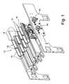
- reference numeral 10 shows an exemplary embodiment of an apparatus for cutting paper logs 11 in a plurality of rolls 12 according to the present invention.
- Such apparatus 10 comprises at least one longitudinal input channel 13 of a log 11 and at least one output channel 14 of the finished rolls 12.
- Channels 13, 14 are arranged in succession among them, are separated by a cutting device 17, for example with blade, and define substantially circular housings 16 having such dimensions as to stably receive log 11 and rolls 12.
- means 18 are provided for moving logs 11 and rolls 12 along the relative channels 13, 14 upstream and downstream of blade 17.
- channels 13, 14 comprise mobile walls 15 so as to selectively vary the diameter of the circular housings 16 for ensuring the stable reception of logs 11 and rolls 12 of various sizes.
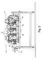
- each one of walls 15 comprises an upper mobile gripping portion 20 and a lower mobile supporting portion 21 for logs 11 and rolls 12.
- the lower mobile supporting portion 21 for logs 11 and rolls 12 is connected through pins 22, 23 with a supporting structure on one side and with an intermediate portion of the upper mobile gripping portion 20 on another side.
- the upper mobile gripping portion 20 generally C-shaped, comprises an upper free end 24 and a base end rotatably connected with a cursor 25 mobile in an inclined slot 28 obtained in the fixed structure.
- cursor 25 is moved by a mobile actuator 26, for controlling the movement of walls 15.
- Cursor 25 is therefore mobile between a first end of the slot which corresponds to the maximum diameter of the circular housings 16, and a second end which corresponds to the minimum diameter of the circular housings 16.
- the mobile actuator 26 is configured so as to engage the upper mobile gripping portion 20 at the base end without generating any vertical compression force of the log towards the apparatus base.
- the upper portion of housings 16 is free and no cover element weighs on them for clamping walls 15.
- the absence of cover elements pressed against the housings facilitates the log advance within the same housings.
- the mobile actuator 26 directly engages cursor 25 for moving it into the inclined slot 28.
- the mobile actuator 26 comprises at least one pusher element 40 acting against cursor 25 where such pusher 26 is of the type shifting along a direction F parallel to the supporting surface 41 of apparatus 10.
- the pusher element 40 comprises a rod element orthogonal to the supporting surface 41 of apparatus 10 and is provided with a first end constrained to a screw 45 for advancing the same pusher 40 and a second free end 42 coupled to cursor 25.
- the second free end 42 of the pusher element 40 comprises a vertical fork housing, or open slot 27 for containing cursor 25.
- the inclined slot 28 has such inclined pattern that by the effect of the shifting of cursor 25 moved by actuator 26, both cursor 25 and the upper mobile gripping portion 20 and the lower mobile supporting portion 21 are moved upwards.
- the movements of walls 15 of each housing 16 may be synchronized with each other automatically or controlled independently.
- all pushers 40 acting on a same side of housings 16 may be controlled in a synchronized manner between each other by means of knobs 43, 44 protruding laterally from apparatus 10.
- knob 43 acting on a knob 43 will move all the right-hand walls 15 of housings 16 and knob 44 will move the left-hand walls 15.
- the screw element 45 extends along the entire apparatus and supports all pushers 40 acting on a same side of housings 16.
- pushers 40 acting on one side of housings 16 may be synchronized with those acting on the other side.
- a wall 15' of a pair defining a housing 16 may exhibit a development greater than the other wall 15, or both walls 15 may exhibit free comb-shaped ends staggered among them so as to allow the mutual partial penetration and surround logs 11 in an optimal manner. It is very easy to understand the operation of the apparatus for cutting paper logs in a plurality of rolls object of the invention.
- Actuators 16 are activated according to the log diameter which, acting on cursor 25, move walls 15 of the same channel 13.
- an apparatus for cutting paper logs in a plurality of rolls according to the present invention achieves the objects described above.
- the apparatus for cutting paper logs in a plurality of rolls according to the present invention offers an alternative solution to the machines known to date and is capable of precisely cutting logs of various sizes without requiring the stop of the apparatus or the manual intervention of an operator.
Landscapes
- Life Sciences & Earth Sciences (AREA)
- Forests & Forestry (AREA)
- Engineering & Computer Science (AREA)
- Mechanical Engineering (AREA)
- Details Of Cutting Devices (AREA)
- Replacement Of Web Rolls (AREA)
- Sanitary Thin Papers (AREA)
Claims (10)
- Vorrichtung (10) zum Schneiden von Papierlangrollen (11) in eine Vielzahl von Einzelrollen (12), die mindestens einen längslaufenden Eingangskanal (13) für die Langrolle (11) und mindestens einen Ausgangskanal (14) für die Einzelrollen (12) umfasst, wobei diese Kanäle (13, 14) runde Gehäuse (16) für die stabile Aufnahme der Langrolle (11) und der Einzelrollen (12) definieren und aufeinanderfolgend angeordnet sind und durch eine Vorrichtung (17) zum Schneiden der Langrolle (11) in die Einzelrollen (12) getrennt sind, wobei Mittel zum Bewegen (18) der Langrolle (11) und der Einzelrollen (12) längs der Kanäle (13, 14) vorgesehen sind, wobei diese Kanäle (13, 14) bewegliche Wände (15) zum selektiven Variieren des Durchmessers der runden Gehäuse (16) zwischen einem Höchstdurchmesser und einem Mindestdurchmesser umfassen, um die stabile Aufnahme von einer Langrolle (11) und Einzelrollen (12) unterschiedlicher Abmessungen zu gewährleisten, wobei jede der Wände (15) einen oberen beweglichen Spannabschnitt (20) und einen unteren beweglichen Tragabschnitt (21) für die Langrollen (11) und die Einzelrollen (12) umfasst, wobei der untere bewegliche Tragabschnitt (21) für die Langrollen (11) und Einzelrollen (12) durch Bolzen (22, 23) auf einer Seite mit einer Konstruktion zum Tragen der Vorrichtung (10) und auf einer anderen Seite mit einem Zwischenbereich des oberen beweglichen Spannabschnitts (20) verbunden ist, wobei der obere bewegliche Spannabschnitt (20) ein freies oberes Endstück (24) und ein Basisendstück umfasst, das drehbar mit einem Läufer (25) verbunden ist, der in einem schrägen Schlitz (28), der in der Konstruktion ausgebildet ist, zwischen einer ersten Position, die dem Höchstdurchmesser der runden Gehäuse (16) entspricht, und einer zweiten Position beweglich ist, die dem Mindestdurchmesser der runden Gehäuse (16) entspricht, wobei ein beweglicher Aktuator (26) zum Bewegen der Wände (15) vorgesehen ist, dadurch gekennzeichnet, dass dieser bewegliche Aktuator (26) an dem Basisendstück in den oberen beweglichen Spannabschnitt (20) eingreift.
- Vorrichtung (10) nach Anspruch 1, dadurch gekennzeichnet, dass der bewegliche Aktuator (26) direkt in den Läufer (25) eingreift, um ihn in dem schrägen Schlitz (28) zu bewegen.
- Vorrichtung (10) nach Anspruch 2, dadurch gekennzeichnet, dass der bewegliche Aktuator (26) mindestens ein Schubelement (40) umfasst, das gegen den Läufer (25) wirkt, wobei sich der Schieber (26) entlang einer zur Tragfläche (41) der Vorrichtung (10) parallelen Richtung (F) zwischen einer ersten Position, in der er den Läufer (25) hin zu einem ersten Ende des Schlitzes (28) zwingt, und einer zweiten Position verschiebt, in der er den Läufer (25) hin zu einem zweiten Ende des Schlitzes (28) zwingt.
- Vorrichtung (10) nach Anspruch 3, dadurch gekennzeichnet, dass das Schubelement (40) ein zur Tragfläche (41) der Vorrichtung (10) rechtwinkliges Stabelement umfasst, das mit einem ersten Endstück, das hin zu einer zur Tragfläche (41) der Vorrichtung (10) parallelen Schraube (41) gezwungen wird, um den Schieber (40) vorwärts zu bewegen, und einem zweiten freien Endstück (42) versehen ist, das mit dem Läufer (25) verbunden ist.
- Vorrichtung (10) nach Anspruch 4, dadurch gekennzeichnet, dass das zweite freie Endstück (42) des Schubelements (40) eine Gabelabschnitt oder offenen senkrechten Schlitzabschnitt (27) für das Zurückhalten und Gleiten des Läufers (25) umfasst.
- Vorrichtung (10) nach Anspruch 5, dadurch gekennzeichnet, dass sie eine Vielzahl von zueinander parallelen runden Gehäusen (16) und eine Vielzahl von gegen die Wände (15) wirkenden Schubelementen (40) umfasst, wobei alle Schieber (40) unabhängig voneinander sind.
- Vorrichtung (10) nach Anspruch 5, dadurch gekennzeichnet, dass sie eine Vielzahl von zueinander parallelen runden Gehäusen (16) und eine Vielzahl von gegen die Wände (15) wirkenden Schubelementen (40) umfasst, wobei alle Schieber (40) auf eine selbe Seite der Gehäuse (16) wirken, wobei sie untereinander synchron mit Hilfe von Knäufen (43, 44) gesteuert werden, die seitlich von der Vorrichtung (10) vorstehen.
- Vorrichtung (10) nach einem der vorhergehenden Ansprüche, dadurch gekennzeichnet, dass die auf eine Seite der Gehäuse (16) wirkenden Schieber (40) mit den Schiebern synchronisiert sind, die auf die andere Seite der Gehäuse (16) wirken.
- Vorrichtung (10) nach einem der vorhergehenden Ansprüche, dadurch gekennzeichnet, dass eine Wand (15') eines Paares von Wänden (15), das das Gehäuse (16) definiert, eine größere Ausdehnung als die andere Wand (15) aufweist.
- Vorrichtung (10) nach einem der vorhergehenden Ansprüche, dadurch gekennzeichnet, dass die Wände (15) freie kammförmige Enden haben, die so gegeneinander versetzt sind, dass das teilweise gegenseitige Eindringen möglich ist.
Applications Claiming Priority (1)
| Application Number | Priority Date | Filing Date | Title |
|---|---|---|---|
| IT000221A ITMI20110221A1 (it) | 2011-02-15 | 2011-02-15 | Apparecchiatura per taglio di log di carta in una pluralitá di rotoli |
Publications (2)
| Publication Number | Publication Date |
|---|---|
| EP2489486A1 EP2489486A1 (de) | 2012-08-22 |
| EP2489486B1 true EP2489486B1 (de) | 2013-09-18 |
Family
ID=43976126
Family Applications (1)
| Application Number | Title | Priority Date | Filing Date |
|---|---|---|---|
| EP20120155227 Active EP2489486B1 (de) | 2011-02-15 | 2012-02-13 | Vorrichtung zum Schneiden von einer Vielzahl von Papierrollen |
Country Status (4)
| Country | Link |
|---|---|
| US (1) | US8950306B2 (de) |
| EP (1) | EP2489486B1 (de) |
| ES (1) | ES2440082T3 (de) |
| IT (1) | ITMI20110221A1 (de) |
Families Citing this family (14)
| Publication number | Priority date | Publication date | Assignee | Title |
|---|---|---|---|---|
| ITMI20111293A1 (it) * | 2011-07-12 | 2013-01-13 | Gambini Int Sa | Dispositivo migliorato per la eliminazione dei rifili di rotoli o log di materiale nastriforme |
| ITMI20120155A1 (it) * | 2012-02-06 | 2013-08-07 | Gambini Int Sa | Apparecchiatura perfezionata per taglio di log di carta in una pluralita' di rotoli |
| CN103538101B (zh) * | 2013-10-16 | 2016-02-10 | 宇宙纸巾技术有限公司 | 圆柱状材料夹持装置 |
| US20170165857A1 (en) * | 2014-02-06 | 2017-06-15 | Futura S.P.A. | Method and a machine for cutting paper logs |
| WO2016124297A1 (en) * | 2015-02-03 | 2016-08-11 | Universal Tissue Technology S.R.L. | Device to clamp logs during the cut thereof and sawing machine comprising said device |
| TWI598198B (zh) * | 2015-06-18 | 2017-09-11 | 全利機械股份有限公司 | 卷筒裁切機之管狀夾持系統 |
| ES2672420T3 (es) * | 2015-06-19 | 2018-06-14 | Gambini International S.A. | Método para alimentar selectivamente rollos de papel que salen de una unidad de sierra de troncos y una unidad de sierra de troncos correspondiente |
| ITUA20163298A1 (it) * | 2016-05-10 | 2017-11-10 | Paper Converting Machine Company Italia S P A | Macchina troncatrice e metodo di taglio di rotoli di materiale in foglio |
| US10279498B2 (en) | 2016-06-17 | 2019-05-07 | Gambini International S.A. | Method for selectively feeding rolls of paper coming out of a log saw unit and relative log saw unit |
| US11584033B2 (en) * | 2016-12-09 | 2023-02-21 | The Procter & Gamble Company | Device for transversally cutting convolutely wound logs of web materials |
| US11065776B2 (en) | 2016-12-09 | 2021-07-20 | The Procter & Gamble Company | Finished products formed from cutting convolutely wound logs of web materials |
| US20180162006A1 (en) * | 2016-12-09 | 2018-06-14 | The Procter & Gamble Company | Clamping device for machines used for transversally cutting convolutely wound logs of web materials |
| TWI676540B (zh) * | 2018-05-07 | 2019-11-11 | 全利機械股份有限公司 | 捲筒式纖維製品的裁切機構 |
| IT202100011042A1 (it) * | 2021-04-30 | 2022-10-30 | Unico Eng S R L | Dispositivo di bloccaggio del rotolo in una troncatrice |
Family Cites Families (15)
| Publication number | Priority date | Publication date | Assignee | Title |
|---|---|---|---|---|
| US2262991A (en) * | 1939-10-14 | 1941-11-18 | D Arrigo Stephen | Broccoli bundling machine |
| DE7932465U1 (de) * | 1979-10-11 | 1980-02-21 | Georg Fischer Ag, Schaffhausen (Schweiz) | Spanneinrichtung zum zentrischen spannen von werkstuecken |
| GB2089708B (en) * | 1980-12-18 | 1984-02-22 | Index Werke Kg Hahn & Tessky | Steady for holding rod-like circular cross-section components |
| IT1145094B (it) * | 1981-09-16 | 1986-11-05 | Martinson Srl | Lunetta autocentrante |
| US4546681A (en) * | 1982-11-15 | 1985-10-15 | Owsen Paul J | Multi-purpose steady rest |
| US4650237A (en) * | 1985-07-25 | 1987-03-17 | Arobotech Systems, Inc. | Automatic centering and gripper apparatus |
| US5058468A (en) * | 1990-09-19 | 1991-10-22 | Arobotech Systems, Inc. | Remote gage steady rest head |
| FR2672834B1 (fr) * | 1991-02-18 | 1993-05-21 | Essilor Int | Organe de serrage et de prehension. |
| US5941513A (en) * | 1996-10-07 | 1999-08-24 | Phd, Inc. | Mounting bracket for modular workpiece holder |
| JP3172515B2 (ja) * | 1999-10-18 | 2001-06-04 | 川之江造機株式会社 | ログペーパー切断装置のログペーパークランプ装置 |
| EP1237684A2 (de) * | 1999-12-03 | 2002-09-11 | C.G. Bretting Manufacturing Co., Inc. | Spannvorrichtung für eine rollensäge sowie dazugehörendes verfahren |
| US6532851B2 (en) * | 2000-12-21 | 2003-03-18 | Paper Converting Machine Company | Apparatus for supporting product during cutting |
| US6699113B2 (en) * | 2001-10-12 | 2004-03-02 | Arobotech Systems, Inc. | Steady rest with vertical adjustment |
| ITFI20030114A1 (it) * | 2003-04-24 | 2004-10-25 | Fabio Perini | Dispositivo per trattenere temporaneamente i logs in macchine troncatrici |
| US8474806B2 (en) * | 2009-01-26 | 2013-07-02 | T&T Engineering Services, Inc. | Pipe gripping apparatus |
-
2011
- 2011-02-15 IT IT000221A patent/ITMI20110221A1/it unknown
-
2012
- 2012-02-13 US US13/372,084 patent/US8950306B2/en active Active
- 2012-02-13 EP EP20120155227 patent/EP2489486B1/de active Active
- 2012-02-13 ES ES12155227T patent/ES2440082T3/es active Active
Also Published As
| Publication number | Publication date |
|---|---|
| US8950306B2 (en) | 2015-02-10 |
| ES2440082T3 (es) | 2014-01-27 |
| ITMI20110221A1 (it) | 2012-08-16 |
| US20120204691A1 (en) | 2012-08-16 |
| EP2489486A1 (de) | 2012-08-22 |
Similar Documents
| Publication | Publication Date | Title |
|---|---|---|
| US8950306B2 (en) | Apparatus for cutting paper logs in a plurality of rolls | |
| CA2074621C (en) | Device (clamp) for retaining rolls or logs by pressure in cutters for the production of toilet paper and other items | |
| US10875202B2 (en) | Industrial slicer having automatic adjustment of the position of the blades | |
| RU2384068C2 (ru) | Устройство для образования кончика рукава на упаковочной оболочке | |
| EP2540429B1 (de) | Schneidanlage zum Schneiden von Holzplatten und dergleichen. | |
| EP3253542A1 (de) | Vorrichtung zum klammen von stämmen zum schneiden davon und sägemaschine mit besagter vorrichtung | |
| MXPA03009913A (es) | PLANTA PARA CORTAR PLACAS CERaMICAS PLANAS COMPACTAS. | |
| EP2021597B1 (de) | Kanalbuchstabenmaschine und verfahren dafür | |
| EP2623279B1 (de) | Verbesserte Vorrichtung zum Schneiden von Papierballen in eine Vielzahl von Rollen | |
| JP6296715B2 (ja) | 板紙用紙に溝付けする装置 | |
| JP2014019582A5 (de) | ||
| EP2462027B1 (de) | Stapelvorrichtung für gruppen von einwegtüchern | |
| EP2233236B1 (de) | Verfahren and Maschine zum Schneiden von Holzplatten oder degleichen | |
| US20150321270A1 (en) | Co-moving hydraulic shears without stand | |
| EP3909875A1 (de) | Eine greifergruppe für eine variable anzahl von dosengruppen zur herstellung von fertigpackungen | |
| CN104044172A (zh) | 一种铡刀设备 | |
| EP1604925B1 (de) | Tragvorrichtung für einen Anleger | |
| JP3162253U (ja) | 麺切り装置 | |
| EP2275238B1 (de) | Maschine für das Schneiden von Holzpaneelen oder Paneelen aus ähnlichem Material | |
| US9004837B2 (en) | Method and device for pressing a book block | |
| CN216037542U (zh) | 切纸机的入料输送机构 | |
| US20190047313A1 (en) | Creasing device for forming creases in paper and bookbinding articles, and machine comprising such device | |
| CN201471530U (zh) | 一种齿轮式虚线打孔装置 | |
| US20090044675A1 (en) | Cutting arrangement having a tip-to-tip blade arrangement | |
| ITPR20060074A1 (it) | Macchina per il taglio di formaggi a pasta dura |
Legal Events
| Date | Code | Title | Description |
|---|---|---|---|
| PUAI | Public reference made under article 153(3) epc to a published international application that has entered the european phase |
Free format text: ORIGINAL CODE: 0009012 |
|
| AK | Designated contracting states |
Kind code of ref document: A1 Designated state(s): AL AT BE BG CH CY CZ DE DK EE ES FI FR GB GR HR HU IE IS IT LI LT LU LV MC MK MT NL NO PL PT RO RS SE SI SK SM TR |
|
| AX | Request for extension of the european patent |
Extension state: BA ME |
|
| 17P | Request for examination filed |
Effective date: 20130214 |
|
| GRAP | Despatch of communication of intention to grant a patent |
Free format text: ORIGINAL CODE: EPIDOSNIGR1 |
|
| RIC1 | Information provided on ipc code assigned before grant |
Ipc: B26D 7/02 20060101AFI20130322BHEP Ipc: B26D 3/16 20060101ALN20130322BHEP |
|
| INTG | Intention to grant announced |
Effective date: 20130419 |
|
| GRAS | Grant fee paid |
Free format text: ORIGINAL CODE: EPIDOSNIGR3 |
|
| GRAA | (expected) grant |
Free format text: ORIGINAL CODE: 0009210 |
|
| AK | Designated contracting states |
Kind code of ref document: B1 Designated state(s): AL AT BE BG CH CY CZ DE DK EE ES FI FR GB GR HR HU IE IS IT LI LT LU LV MC MK MT NL NO PL PT RO RS SE SI SK SM TR |
|
| REG | Reference to a national code |
Ref country code: GB Ref legal event code: FG4D |
|
| REG | Reference to a national code |
Ref country code: CH Ref legal event code: EP |
|
| REG | Reference to a national code |
Ref country code: IE Ref legal event code: FG4D |
|
| REG | Reference to a national code |
Ref country code: AT Ref legal event code: REF Ref document number: 632485 Country of ref document: AT Kind code of ref document: T Effective date: 20131015 |
|
| REG | Reference to a national code |
Ref country code: DE Ref legal event code: R096 Ref document number: 602012000290 Country of ref document: DE Effective date: 20131107 |
|
| REG | Reference to a national code |
Ref country code: ES Ref legal event code: FG2A Ref document number: 2440082 Country of ref document: ES Kind code of ref document: T3 Effective date: 20140127 |
|
| PG25 | Lapsed in a contracting state [announced via postgrant information from national office to epo] |
Ref country code: HR Free format text: LAPSE BECAUSE OF FAILURE TO SUBMIT A TRANSLATION OF THE DESCRIPTION OR TO PAY THE FEE WITHIN THE PRESCRIBED TIME-LIMIT Effective date: 20130918 Ref country code: SE Free format text: LAPSE BECAUSE OF FAILURE TO SUBMIT A TRANSLATION OF THE DESCRIPTION OR TO PAY THE FEE WITHIN THE PRESCRIBED TIME-LIMIT Effective date: 20130918 Ref country code: LT Free format text: LAPSE BECAUSE OF FAILURE TO SUBMIT A TRANSLATION OF THE DESCRIPTION OR TO PAY THE FEE WITHIN THE PRESCRIBED TIME-LIMIT Effective date: 20130918 Ref country code: NO Free format text: LAPSE BECAUSE OF FAILURE TO SUBMIT A TRANSLATION OF THE DESCRIPTION OR TO PAY THE FEE WITHIN THE PRESCRIBED TIME-LIMIT Effective date: 20131218 Ref country code: CY Free format text: LAPSE BECAUSE OF FAILURE TO SUBMIT A TRANSLATION OF THE DESCRIPTION OR TO PAY THE FEE WITHIN THE PRESCRIBED TIME-LIMIT Effective date: 20130911 |
|
| REG | Reference to a national code |
Ref country code: NL Ref legal event code: VDEP Effective date: 20130918 |
|
| REG | Reference to a national code |
Ref country code: AT Ref legal event code: MK05 Ref document number: 632485 Country of ref document: AT Kind code of ref document: T Effective date: 20130918 |
|
| REG | Reference to a national code |
Ref country code: LT Ref legal event code: MG4D |
|
| PG25 | Lapsed in a contracting state [announced via postgrant information from national office to epo] |
Ref country code: LV Free format text: LAPSE BECAUSE OF FAILURE TO SUBMIT A TRANSLATION OF THE DESCRIPTION OR TO PAY THE FEE WITHIN THE PRESCRIBED TIME-LIMIT Effective date: 20130918 Ref country code: SI Free format text: LAPSE BECAUSE OF FAILURE TO SUBMIT A TRANSLATION OF THE DESCRIPTION OR TO PAY THE FEE WITHIN THE PRESCRIBED TIME-LIMIT Effective date: 20130918 Ref country code: RS Free format text: LAPSE BECAUSE OF FAILURE TO SUBMIT A TRANSLATION OF THE DESCRIPTION OR TO PAY THE FEE WITHIN THE PRESCRIBED TIME-LIMIT Effective date: 20130918 Ref country code: GR Free format text: LAPSE BECAUSE OF FAILURE TO SUBMIT A TRANSLATION OF THE DESCRIPTION OR TO PAY THE FEE WITHIN THE PRESCRIBED TIME-LIMIT Effective date: 20131219 Ref country code: FI Free format text: LAPSE BECAUSE OF FAILURE TO SUBMIT A TRANSLATION OF THE DESCRIPTION OR TO PAY THE FEE WITHIN THE PRESCRIBED TIME-LIMIT Effective date: 20130918 |
|
| PG25 | Lapsed in a contracting state [announced via postgrant information from national office to epo] |
Ref country code: BE Free format text: LAPSE BECAUSE OF FAILURE TO SUBMIT A TRANSLATION OF THE DESCRIPTION OR TO PAY THE FEE WITHIN THE PRESCRIBED TIME-LIMIT Effective date: 20130918 Ref country code: CY Free format text: LAPSE BECAUSE OF FAILURE TO SUBMIT A TRANSLATION OF THE DESCRIPTION OR TO PAY THE FEE WITHIN THE PRESCRIBED TIME-LIMIT Effective date: 20130918 |
|
| PG25 | Lapsed in a contracting state [announced via postgrant information from national office to epo] |
Ref country code: IS Free format text: LAPSE BECAUSE OF FAILURE TO SUBMIT A TRANSLATION OF THE DESCRIPTION OR TO PAY THE FEE WITHIN THE PRESCRIBED TIME-LIMIT Effective date: 20140118 Ref country code: NL Free format text: LAPSE BECAUSE OF FAILURE TO SUBMIT A TRANSLATION OF THE DESCRIPTION OR TO PAY THE FEE WITHIN THE PRESCRIBED TIME-LIMIT Effective date: 20130918 Ref country code: SK Free format text: LAPSE BECAUSE OF FAILURE TO SUBMIT A TRANSLATION OF THE DESCRIPTION OR TO PAY THE FEE WITHIN THE PRESCRIBED TIME-LIMIT Effective date: 20130918 Ref country code: CZ Free format text: LAPSE BECAUSE OF FAILURE TO SUBMIT A TRANSLATION OF THE DESCRIPTION OR TO PAY THE FEE WITHIN THE PRESCRIBED TIME-LIMIT Effective date: 20130918 Ref country code: EE Free format text: LAPSE BECAUSE OF FAILURE TO SUBMIT A TRANSLATION OF THE DESCRIPTION OR TO PAY THE FEE WITHIN THE PRESCRIBED TIME-LIMIT Effective date: 20130918 |
|
| PG25 | Lapsed in a contracting state [announced via postgrant information from national office to epo] |
Ref country code: PL Free format text: LAPSE BECAUSE OF FAILURE TO SUBMIT A TRANSLATION OF THE DESCRIPTION OR TO PAY THE FEE WITHIN THE PRESCRIBED TIME-LIMIT Effective date: 20130918 Ref country code: AT Free format text: LAPSE BECAUSE OF FAILURE TO SUBMIT A TRANSLATION OF THE DESCRIPTION OR TO PAY THE FEE WITHIN THE PRESCRIBED TIME-LIMIT Effective date: 20130918 |
|
| REG | Reference to a national code |
Ref country code: DE Ref legal event code: R097 Ref document number: 602012000290 Country of ref document: DE |
|
| PG25 | Lapsed in a contracting state [announced via postgrant information from national office to epo] |
Ref country code: PT Free format text: LAPSE BECAUSE OF FAILURE TO SUBMIT A TRANSLATION OF THE DESCRIPTION OR TO PAY THE FEE WITHIN THE PRESCRIBED TIME-LIMIT Effective date: 20140120 |
|
| PLBE | No opposition filed within time limit |
Free format text: ORIGINAL CODE: 0009261 |
|
| STAA | Information on the status of an ep patent application or granted ep patent |
Free format text: STATUS: NO OPPOSITION FILED WITHIN TIME LIMIT |
|
| 26N | No opposition filed |
Effective date: 20140619 |
|
| PG25 | Lapsed in a contracting state [announced via postgrant information from national office to epo] |
Ref country code: MC Free format text: LAPSE BECAUSE OF FAILURE TO SUBMIT A TRANSLATION OF THE DESCRIPTION OR TO PAY THE FEE WITHIN THE PRESCRIBED TIME-LIMIT Effective date: 20130918 Ref country code: LU Free format text: LAPSE BECAUSE OF FAILURE TO SUBMIT A TRANSLATION OF THE DESCRIPTION OR TO PAY THE FEE WITHIN THE PRESCRIBED TIME-LIMIT Effective date: 20140213 Ref country code: DK Free format text: LAPSE BECAUSE OF FAILURE TO SUBMIT A TRANSLATION OF THE DESCRIPTION OR TO PAY THE FEE WITHIN THE PRESCRIBED TIME-LIMIT Effective date: 20130918 |
|
| REG | Reference to a national code |
Ref country code: DE Ref legal event code: R097 Ref document number: 602012000290 Country of ref document: DE Effective date: 20140619 |
|
| REG | Reference to a national code |
Ref country code: IE Ref legal event code: MM4A |
|
| PG25 | Lapsed in a contracting state [announced via postgrant information from national office to epo] |
Ref country code: IE Free format text: LAPSE BECAUSE OF NON-PAYMENT OF DUE FEES Effective date: 20140213 |
|
| REG | Reference to a national code |
Ref country code: CH Ref legal event code: PL |
|
| PG25 | Lapsed in a contracting state [announced via postgrant information from national office to epo] |
Ref country code: CH Free format text: LAPSE BECAUSE OF NON-PAYMENT OF DUE FEES Effective date: 20150228 Ref country code: LI Free format text: LAPSE BECAUSE OF NON-PAYMENT OF DUE FEES Effective date: 20150228 |
|
| REG | Reference to a national code |
Ref country code: FR Ref legal event code: PLFP Year of fee payment: 5 |
|
| PG25 | Lapsed in a contracting state [announced via postgrant information from national office to epo] |
Ref country code: MT Free format text: LAPSE BECAUSE OF FAILURE TO SUBMIT A TRANSLATION OF THE DESCRIPTION OR TO PAY THE FEE WITHIN THE PRESCRIBED TIME-LIMIT Effective date: 20130918 |
|
| PG25 | Lapsed in a contracting state [announced via postgrant information from national office to epo] |
Ref country code: SM Free format text: LAPSE BECAUSE OF FAILURE TO SUBMIT A TRANSLATION OF THE DESCRIPTION OR TO PAY THE FEE WITHIN THE PRESCRIBED TIME-LIMIT Effective date: 20130918 |
|
| PG25 | Lapsed in a contracting state [announced via postgrant information from national office to epo] |
Ref country code: RO Free format text: LAPSE BECAUSE OF FAILURE TO SUBMIT A TRANSLATION OF THE DESCRIPTION OR TO PAY THE FEE WITHIN THE PRESCRIBED TIME-LIMIT Effective date: 20130918 |
|
| PG25 | Lapsed in a contracting state [announced via postgrant information from national office to epo] |
Ref country code: BG Free format text: LAPSE BECAUSE OF FAILURE TO SUBMIT A TRANSLATION OF THE DESCRIPTION OR TO PAY THE FEE WITHIN THE PRESCRIBED TIME-LIMIT Effective date: 20130918 |
|
| PG25 | Lapsed in a contracting state [announced via postgrant information from national office to epo] |
Ref country code: HU Free format text: LAPSE BECAUSE OF FAILURE TO SUBMIT A TRANSLATION OF THE DESCRIPTION OR TO PAY THE FEE WITHIN THE PRESCRIBED TIME-LIMIT; INVALID AB INITIO Effective date: 20120213 Ref country code: TR Free format text: LAPSE BECAUSE OF FAILURE TO SUBMIT A TRANSLATION OF THE DESCRIPTION OR TO PAY THE FEE WITHIN THE PRESCRIBED TIME-LIMIT Effective date: 20130918 |
|
| REG | Reference to a national code |
Ref country code: FR Ref legal event code: PLFP Year of fee payment: 6 |
|
| REG | Reference to a national code |
Ref country code: FR Ref legal event code: PLFP Year of fee payment: 7 |
|
| PG25 | Lapsed in a contracting state [announced via postgrant information from national office to epo] |
Ref country code: MK Free format text: LAPSE BECAUSE OF FAILURE TO SUBMIT A TRANSLATION OF THE DESCRIPTION OR TO PAY THE FEE WITHIN THE PRESCRIBED TIME-LIMIT Effective date: 20130918 |
|
| PG25 | Lapsed in a contracting state [announced via postgrant information from national office to epo] |
Ref country code: AL Free format text: LAPSE BECAUSE OF FAILURE TO SUBMIT A TRANSLATION OF THE DESCRIPTION OR TO PAY THE FEE WITHIN THE PRESCRIBED TIME-LIMIT Effective date: 20130918 |
|
| P01 | Opt-out of the competence of the unified patent court (upc) registered |
Effective date: 20230508 |
|
| PGFP | Annual fee paid to national office [announced via postgrant information from national office to epo] |
Ref country code: FR Payment date: 20251208 Year of fee payment: 15 |
|
| PGFP | Annual fee paid to national office [announced via postgrant information from national office to epo] |
Ref country code: GB Payment date: 20260106 Year of fee payment: 15 |
|
| PGFP | Annual fee paid to national office [announced via postgrant information from national office to epo] |
Ref country code: ES Payment date: 20260310 Year of fee payment: 15 |
|
| PGFP | Annual fee paid to national office [announced via postgrant information from national office to epo] |
Ref country code: DE Payment date: 20251216 Year of fee payment: 15 |
|
| PGFP | Annual fee paid to national office [announced via postgrant information from national office to epo] |
Ref country code: IT Payment date: 20260204 Year of fee payment: 15 |