EP2489461B1 - Wire containing flux for gas-sealed arc welding, allowing all-position welding - Google Patents
Wire containing flux for gas-sealed arc welding, allowing all-position welding Download PDFInfo
- Publication number
- EP2489461B1 EP2489461B1 EP10837713.6A EP10837713A EP2489461B1 EP 2489461 B1 EP2489461 B1 EP 2489461B1 EP 10837713 A EP10837713 A EP 10837713A EP 2489461 B1 EP2489461 B1 EP 2489461B1
- Authority
- EP
- European Patent Office
- Prior art keywords
- good
- inv
- none
- wire
- mass
- Prior art date
- Legal status (The legal status is an assumption and is not a legal conclusion. Google has not performed a legal analysis and makes no representation as to the accuracy of the status listed.)
- Not-in-force
Links
Images


Classifications
-
- B—PERFORMING OPERATIONS; TRANSPORTING
- B23—MACHINE TOOLS; METAL-WORKING NOT OTHERWISE PROVIDED FOR
- B23K—SOLDERING OR UNSOLDERING; WELDING; CLADDING OR PLATING BY SOLDERING OR WELDING; CUTTING BY APPLYING HEAT LOCALLY, e.g. FLAME CUTTING; WORKING BY LASER BEAM
- B23K35/00—Rods, electrodes, materials, or media, for use in soldering, welding, or cutting
- B23K35/02—Rods, electrodes, materials, or media, for use in soldering, welding, or cutting characterised by mechanical features, e.g. shape
- B23K35/0255—Rods, electrodes, materials, or media, for use in soldering, welding, or cutting characterised by mechanical features, e.g. shape for use in welding
- B23K35/0261—Rods, electrodes, wires
- B23K35/0266—Rods, electrodes, wires flux-cored
-
- B—PERFORMING OPERATIONS; TRANSPORTING
- B23—MACHINE TOOLS; METAL-WORKING NOT OTHERWISE PROVIDED FOR
- B23K—SOLDERING OR UNSOLDERING; WELDING; CLADDING OR PLATING BY SOLDERING OR WELDING; CUTTING BY APPLYING HEAT LOCALLY, e.g. FLAME CUTTING; WORKING BY LASER BEAM
- B23K35/00—Rods, electrodes, materials, or media, for use in soldering, welding, or cutting
- B23K35/02—Rods, electrodes, materials, or media, for use in soldering, welding, or cutting characterised by mechanical features, e.g. shape
-
- B—PERFORMING OPERATIONS; TRANSPORTING
- B23—MACHINE TOOLS; METAL-WORKING NOT OTHERWISE PROVIDED FOR
- B23K—SOLDERING OR UNSOLDERING; WELDING; CLADDING OR PLATING BY SOLDERING OR WELDING; CUTTING BY APPLYING HEAT LOCALLY, e.g. FLAME CUTTING; WORKING BY LASER BEAM
- B23K35/00—Rods, electrodes, materials, or media, for use in soldering, welding, or cutting
- B23K35/22—Rods, electrodes, materials, or media, for use in soldering, welding, or cutting characterised by the composition or nature of the material
- B23K35/24—Selection of soldering or welding materials proper
- B23K35/30—Selection of soldering or welding materials proper with the principal constituent melting at less than 1550 degrees C
-
- B—PERFORMING OPERATIONS; TRANSPORTING
- B23—MACHINE TOOLS; METAL-WORKING NOT OTHERWISE PROVIDED FOR
- B23K—SOLDERING OR UNSOLDERING; WELDING; CLADDING OR PLATING BY SOLDERING OR WELDING; CUTTING BY APPLYING HEAT LOCALLY, e.g. FLAME CUTTING; WORKING BY LASER BEAM
- B23K35/00—Rods, electrodes, materials, or media, for use in soldering, welding, or cutting
- B23K35/22—Rods, electrodes, materials, or media, for use in soldering, welding, or cutting characterised by the composition or nature of the material
- B23K35/36—Selection of non-metallic compositions, e.g. coatings, fluxes; Selection of soldering or welding materials, conjoint with selection of non-metallic compositions, both selections being of interest
- B23K35/3601—Selection of non-metallic compositions, e.g. coatings, fluxes; Selection of soldering or welding materials, conjoint with selection of non-metallic compositions, both selections being of interest with inorganic compounds as principal constituents
- B23K35/3602—Carbonates, basic oxides or hydroxides
-
- B—PERFORMING OPERATIONS; TRANSPORTING
- B23—MACHINE TOOLS; METAL-WORKING NOT OTHERWISE PROVIDED FOR
- B23K—SOLDERING OR UNSOLDERING; WELDING; CLADDING OR PLATING BY SOLDERING OR WELDING; CUTTING BY APPLYING HEAT LOCALLY, e.g. FLAME CUTTING; WORKING BY LASER BEAM
- B23K35/00—Rods, electrodes, materials, or media, for use in soldering, welding, or cutting
- B23K35/22—Rods, electrodes, materials, or media, for use in soldering, welding, or cutting characterised by the composition or nature of the material
- B23K35/36—Selection of non-metallic compositions, e.g. coatings, fluxes; Selection of soldering or welding materials, conjoint with selection of non-metallic compositions, both selections being of interest
- B23K35/3601—Selection of non-metallic compositions, e.g. coatings, fluxes; Selection of soldering or welding materials, conjoint with selection of non-metallic compositions, both selections being of interest with inorganic compounds as principal constituents
- B23K35/3603—Halide salts
- B23K35/3605—Fluorides
-
- B—PERFORMING OPERATIONS; TRANSPORTING
- B23—MACHINE TOOLS; METAL-WORKING NOT OTHERWISE PROVIDED FOR
- B23K—SOLDERING OR UNSOLDERING; WELDING; CLADDING OR PLATING BY SOLDERING OR WELDING; CUTTING BY APPLYING HEAT LOCALLY, e.g. FLAME CUTTING; WORKING BY LASER BEAM
- B23K35/00—Rods, electrodes, materials, or media, for use in soldering, welding, or cutting
- B23K35/22—Rods, electrodes, materials, or media, for use in soldering, welding, or cutting characterised by the composition or nature of the material
- B23K35/36—Selection of non-metallic compositions, e.g. coatings, fluxes; Selection of soldering or welding materials, conjoint with selection of non-metallic compositions, both selections being of interest
- B23K35/362—Selection of compositions of fluxes
-
- B—PERFORMING OPERATIONS; TRANSPORTING
- B23—MACHINE TOOLS; METAL-WORKING NOT OTHERWISE PROVIDED FOR
- B23K—SOLDERING OR UNSOLDERING; WELDING; CLADDING OR PLATING BY SOLDERING OR WELDING; CUTTING BY APPLYING HEAT LOCALLY, e.g. FLAME CUTTING; WORKING BY LASER BEAM
- B23K35/00—Rods, electrodes, materials, or media, for use in soldering, welding, or cutting
- B23K35/22—Rods, electrodes, materials, or media, for use in soldering, welding, or cutting characterised by the composition or nature of the material
- B23K35/36—Selection of non-metallic compositions, e.g. coatings, fluxes; Selection of soldering or welding materials, conjoint with selection of non-metallic compositions, both selections being of interest
- B23K35/368—Selection of non-metallic compositions of core materials either alone or conjoint with selection of soldering or welding materials
Definitions
- the present invention relates to a flux-cored wire for gas shielded arc welding use enabling all-position welding, more particularly relates to a flux-cored wire for gas shielded arc welding use which can reduce the oxygen of the weld metal to 300 mass ppm or less to obtain a weld metal which is excellent in toughness and which can be used by direct current reverse polarity (polarity making welding wire positive electrode).
- Flux-cored wire for gas shielded welding use is spreading widely throughout the industrial world as a welding material which enables use of a high efficiency welding method, but the majority of this is flux-cored wire having Ti oxides such as rutile as the main slag-forming material (below, sometimes abbreviated as "rutile-type FCW").
- a rutile-type FCW has excellent welding work efficiency and has the feature of enable easy welding at flat, vertical, overhead, horizontal, and other various welding positions.
- the high content of oxygen of the weld metal becomes a problem. That is, when using a rutile-type FCW, in weld metal of high strength steel or low temperature use steel, securing the necessary extent of toughness often becomes difficult.
- the facts that this is caused by the oxygen in the weld metal being present as non-metal inclusions and that these inclusions become the initiation points of cracks has been well known from previous research works.
- a rutile-type FCW where reduction of the amount of oxygen of the weld metal is attempted has also been studied up to now. The specific results of the studies are disclosed in for example PLT's 1 to 3 etc.
- the deoxidizing elements Si, Mn, Mg, and Ti are added to restrict the total amount of oxides, including TiO 2 , and study the reduction of oxygen in the weld metal, but in the examples, only an effect of reduction down to 350 mass ppm is confirmed. The improvement is insufficient.
- PLT 3 use of restriction of the total amount of oxides, including TiO 2 , addition of CaF 2 , and addition of the deoxidizing elements Si, Mn, and Mg to reduce oxygen in weld metal is studied, but the amount of oxygen of the weld metal is 300 mass ppm or more. In this invention as well, the amount of oxygen of the weld metal cannot be sufficiently reduced.
- Flux-cored wire includes, in addition to the rutile-based wire, wire using fluorides as main slag-forming materials (below, sometimes indicated as "fluoride-based FCW").
- a fluoride-based FCW differs from a rutile-type FCW in that it enables easy reduction of the amount of oxygen of the weld metal, but has the issues that it is limited in welding position to flat or horizontal fillet and that vertical, overhead, and horizontal welding are extremely difficult. Specific case studies are for example disclosed by PLT's 4 to 7 which are listed below.
- the content of the amounts of BaF 2 , Ni, Mn, C, Al, Si, and oxides is restricted to reduce the amount of oxygen of the weld metal down to 50 mass ppm, but this is predicated on welding by a direct current straight polarity using the welding wire as the negative electrode. With direct current straight polarity, lack of fusion easily occurs and the arc also becomes unstable, so the discovery which is disclosed here is also not sufficient.
- PLT 6 a flux which contains CaF 2 and which contains composite oxides of alkali metals or alkali earth metals and Ti and Si is used to reduce the amount of oxygen of the weld metal down to 251 mass ppm, but there is no description of vertical, overhead, and horizontal welding. From PLT 6, no technical suggestions at all are obtained on flux-cored wire which enables all-position welding.
- PLT 7 as an essential condition for enabling vertical welding, the content of Al is limited to 0.3% or more, so there is the issue that the weld metal deteriorates in toughness. In PLT 7, the deterioration in toughness cannot be completely avoided, so in a Charpy test, a 55J or higher absorbed energy is deemed passing, but with a 55J absorbed energy, there would be many structures which would not satisfy the design standard.
- flux-cored wires for gas shield are welding are disclosed in JP-2-207996 , JP-2-217195 , JP-H10-296486 and JP-H09-248694 .
- the present invention was made in consideration of the above problems in the prior art and has as its object the provision of flux-cored wire for gas shielded welding use which has a totally new flux composition never before known in the past.
- the gist of the present invention for solving the above problems is as follows:
- wire of the present invention it is possible to strikingly reduce the amount of oxygen of the weld metal. Further, it becomes possible to use as is the direct current reverse polarity which is widely spread through the industrial world to enable welding in the flat, vertical, overhead, and horizontal positions. This discovery enables simultaneous achievement of greater welding work efficiency and improved reliability of welded joints. The value of utilization in industry can be said to be extremely high.
- the high melting point substance CaO is contained as an essential ingredient.
- CaO is an oxide, but is a strongly basic substance. Even if contained in wire, the amount of oxygen of the weld metal is never remarkably increased. Further, the melting point of CaO is an extremely high temperature of about 2570°C, it is also possible to raise the melting point of the slag.
- the content of CaO as a mass% with respect to the wire total mass is less than 0.2%, it is impossible to raise the melting point of the slag to an extent enabling welding in the vertical, overhead, and horizontal positions. Conversely, if more than 7.0% is contained, the slag melting point is too high, so solidification of the slag becomes faster and the fluidity of the slag cannot be secured, so slag inclusions easily occur.
- the content of CaO is made a mass% with respect to the wire total mass of 0.7% or more and 6.3% or less. Furthermore, to simultaneously obtain the spatter reducing effect and undercut inhibiting effect by arc stabilization, the content of CaO is made a mass% with respect to the wire total mass of 1.4% or more and 5.6% or less in range. According to the present invention the lower limit of CaO is made 1.7% or more and the upper limit of CaO is made 4.9% or less.
- the content is calculated using the mass of only the CaO part.
- These fluorides are effective for raising the basicity of the slag and reducing the amount of oxygen of the weld metal.
- the slag melting point can be adjusted to a suitable temperature.
- the melting point of CaO is an extremely high temperature of about 2570°C, but these four fluorides have melting points in the extremely close range of 1255°C to 1400°C, so one or more of these four fluorides may be contained.
- the total mass of the one or more of these four fluorides, to express this effect, has to be a mass% with respect to the wire total mass of 1.0% or more. Furthermore, the total mass of the one or more of MgF 2 , CaF 2 , SrF 2 , and BaF 2 and the CaO has to be a mass% with respect to the wire total mass of 3.0% or more and 12.0% or less.
- the total mass of the one or more of MgF 2 , CaF 2 , SrF 2 , and BaF 2 and the CaO is defined as 3.0% or more and 12.0% or less with respect to the wire total mass.
- the arc stability is further improved and as a result the effect of stabilizing the bead width is obtained.
- the total content of the one or more of MgF 2 , CaF 2 , SrF 2 , and BaF 2 and the CaO is preferably 4.0% or more and 10.0% or less with respect to the wire total mass.
- the lower limit may be made 5.0% or more and the upper limit may be made 9.0% or less.
- the metal state Si, Al, Ti, Mg, Zr, Ca, Ce, and La all are elements which have powerful deoxidizing actions and are effective for reducing the oxygen in the weld metal.
- One or more of these elements are added in a mass% with respect to the wire total mass of 0.2% or more and 2.0% or less.
- the content of Al is set to a mass% with respect to the wire total mass of less than 0.3%. In accordance with need, the content may be restricted to 0.2% or less or 0.1% or less.
- the content is too small and there is no effect on the reduction of the amount of oxygen of the weld metal. Further, if more than 2.0% is included, hard microstructures such as martensite-austenite constituents (hereinafter abbreviated as "MAC") easily form in the weld metal and the toughness of the weld metal is degraded.
- MAC martensite-austenite constituents
- the total mass of one or more of the metal states Si, Al, Ti, Mg, Zr, Ca, Ce, and La was made a mass% with respect to the wire total mass of 0.2% or more and 2.0% or less.
- the total mass may also be made, in accordance with need, a lower limit of 0.6% or more or 0.8% or more and an upper limit of 1.8% or less or 1.5% or less.
- these metal elements do not necessarily have to be pure metals (inclusion of unavoidable impurities is possible). There is no problem at all even if included in the form of an alloy such as Al-Mg. Note that, here, a deoxidation reaction during the welding is assumed, so Si, Al, Ti, Mg, Zr, Ca, Ce, and La are which are contained as oxides, fluorides, and carbonates are excluded. Further, whether these metal elements are contained in the steel sheath or contained in flux, the effect is the same, so inclusion in either the steel sheath or flux is possible.
- the present invention focuses on obtaining a weld metal with a high toughness, but an increase in toughness of the weld metal is not achieved by just the reduction of the oxygen. If the hardenability of the weld metal is not controlled to a suitable range, the weld metal comes to have coarse microstructures and hard microstructures. In this state, no matter how low the oxygen is reduced to, a high toughness weld metal cannot be obtained.
- ⁇ N C + N Si / 30 + N Mn / 20 + N Cu / 20 + N Ni / 60 + N Cr / 20 + N Mo / 15 + N V / 10 + N Nb / 10 + 5 N
- P and S are widely known as harmful elements causing solidification cracks, a reduction in toughness, etc., so P and S are restricted to a total mass of a mass% with respect to the wire total mass of 0.040% or less.
- the total mass of P and S is preferably made as low as possible, but making the mass ratio with respect to the wire total mass 0.001% or less forces an excessive load on the refining step and remarkably impairs productivity, so this is not realistic. Therefore, the total mass of P and S does not have to be reduced to less than 0.001% with respect to the wire total mass.
- Si oxides, Mn oxides, Al oxides, Ti oxides, B oxides, and Zr oxides will be explained.
- these oxides are contained in the slag, the amount of oxygen of the weld metal increases. Therefore, to reduce the amount of oxygen of the weld metal, the content of these oxides is preferably kept as low as possible.
- these oxides have the effect of suppressing bead offset since when the weld bead is covered by slag, the uniformity of the covering is enhanced and the behavior of the molten pool is stabilized.
- the inventors experimentally searched for the ranges of contents of these oxides by which the amount of oxygen of the weld metal can be stably reduced to 300 mass ppm or less.
- the inventors discovered that if the total mass of the Si oxides, Mn oxides, Al oxides, Ti oxides, B oxides, and Zr oxides is a mass% with respect to the wire total mass of 0.2% or more and 3.0% or less, it is possible to suppress the amount of oxygen of the weld metal to 300 mass ppm or less and simultaneously realize the effect of suppression of bead offset.
- the total mass of Si oxides, Mn oxides, Al oxides, Ti oxides, B oxides, and Zr oxides has to be restricted to a mass% with respect to the wire total mass of 0.2% or more and 3.0% or less. Further, the total mass may, in accordance with need, be restricted to a lower limit of 0.5% or more or 0.7% or more and to an upper limit of 2.8% or less or 2.2% or less.
- the masses of the corresponding parts are calculated by deeming the part of Al 2 O 3 the Al oxides and deeming the part of SiO 2 the Si oxides so as to find the total mass.
- the content of the Si oxides is defined as the SiO 2 converted value, the content of the Mn oxides as the MnO 2 converted value, the content of the Al oxides as the Al 2 O 3 converted value, the content of the Ti oxides as the TiO 2 converted value, the content of the B oxides as the B 2 O 3 converted value, and the content of the Zr oxides as the ZrO 2 converted value.
- the balance other than the above ingredients consists of Fe, an arc stabilizer, and unavoidable impurities.
- the content of the iron powder in the flux which is filled in the steel sheath has to be a mass% with respect to the wire total mass of 5.0% or less. Improvement of the welding efficiency and improvement of the arc stability due to the inclusion of iron powder in the flux are known, but iron powder is a powder, so has a large surface area so sometimes the oxygen of the weld metal is increased by the extremely thin iron oxide which is inevitably formed on the iron powder surface.
- the content of iron powder which is contained in the flux may be restricted to 4.0% or less or 2.4% or less in accordance with need.
- the mass corresponding to the Fe in the alloy is added to the iron powder defined here.
- oxides, fluorides, carbonates, etc. including Li, Na, K, and Rb which are known in the prior art may be suitably selected for use.
- the mass of the arc stabilizer is suitably made a mass ratio with respect to the wire total mass of 0.01% or more and 1.0% or less. A content in this range is preferable.
- the total content of one or more of CaCO 3 , MgCO 3 , SrCO 3 , and BaCO 3 is preferably a mass% with respect to the wire total mass of 0.1% or more.
- the gas which is produced from inside the wire results in droplets of liquid being splattered from the tip of the wire resulting in a remarkable increase in the large size spatter.
- the total content of one or more of CaCO 3 , MgCO 3 , SrCO 3 , and BaCO 3 is preferably a mass% with respect to the wire total mass of 0.1% or more and 4.0% or less.
- the lower limit is more preferably made 0.7% or more or 1.4% or more and the upper limit is more preferably made 3.6% or less or 2.3% or less.
- CaCO 3 , MgCO 3 , SrCO 3 , and BaCO 3 are respectively, as shown in the following formula (2) to formula (5), substances which contain CaO, MgO, BaO, and SrO.
- the CaO, MgO, SrO, and BaO which are formed by heat decomposition are added to the contents of the above-mentioned CaO and later explained MgO, BaO, and SrO.
- MgO, SrO, and BaO act to reduce the viscosity of the slag, so have the effect of smoothening the toe of the weld bead and suppressing concentration of stress at a weld joint.
- inclusion by a mass% with respect to the wire total mass of 0.1% or more is necessary, but if the content is too great, the slag remarkably falls in viscosity, so the molten pool cannot be maintained in vertical, overhead, and horizontal welding and welding easily becomes impossible.
- the total content is preferably restricted to 0.1% or more and 3.2% or less with respect to the wire total mass. Further, the total content is, in accordance with need, restricted to a lower limit of 0.3% or more or 0.5% or more and to an upper limit of 2.7% or less or 2.0% or less.
- the wire of the present invention particularly preferably has no slit-shaped opening in the steel sheath causing moisture absorption.
- the flux which is used in the wire of the present invention contains a substance such as CaO, MgO, BaO, SrO, and fluorides which basically easily absorb moisture. For this reason, eliminating the slit-shaped opening causing moisture absorption is extremely useful from the viewpoint of preventing moisture absorption of the wire and stabilizing the quality of the welding wire.
- the lubrication oil which is coated on the wire surface is preferably an oil not containing H such as perfluoro polyether.
- the diameter of the wire of the present invention is not particularly limited, but considering the welding efficiency and the wire productivity, 1.2 mm to 1.6 mm in range is preferable.
- the total mass of the flux which is filled in the steel sheath is preferably a mass% with respect to the wire total mass (below, this value being referred to as the "flux filling rate") of 6.0% or more and 18.0% or less.
- the flux which is contained in the steel sheath is in a powder state. The flux is stabilized in position inside the wire by being held from the steel sheath. If the flux filling rate is less than 6.0%, the amount of flux which is present becomes too small for the space formed inside of the steel sheath and the strength of inclusion of the flux becomes weak. For this reason, there is a high possibility of the flux ending up moving inside the wire and the ingredients in the wire becoming unstable.
- the flux filling rate is preferably 6.0% or more and 18.0% or less.
- the wire of the present invention CaO, MgO, Si oxides, and Ti oxides are observed to tend to affect the slag peeling. From the viewpoint of expression of better slag peeling, in the mass ratio with respect to the wire total mass, the ratio of (CaO+MgO)/(Ti oxides+Si oxides) preferably exceeds 1.50.
- the steel sheath of the chemical composition which is shown in Table 1 is formed into a U-shape as shown in FIG. 1 .
- flux is filled inside the steel sheath from the top.
- the sheath is formed into an O-shape.
- the resultant slitted wire is drawn to a prototype wire of a diameter of ⁇ 1.2 mm by a drawing step.
- a wire with no slit is formed by filling the steel sheath with flux, then welding together its seam so as to eliminate the slit-shaped opening in the steel sheet which causes absorption of moisture to the flux, then drawing the wire after this step to finish it to prototype wire of a diameter of ⁇ 1.2 mm.
- the ingredients of the wire were adjusted by the flux which is filled inside the steel sheath in all cases.
- Table 1 (mass%) C Si Mn P S Balance 0.03 0.10 0.50 0.007 0.005 Fe and unavoidable impurities
- SM490B steel plate defined in JIS G 3106
- grooves shown FIG. 2 and FIG. 3 were formed and the above-mentioned prototype wires were welded at the flat, vertical, overhead, and horizontal welding positions and evaluated.
- the chemical composition of the SM490B steel material which is used for the tests are shown in Table 2. Further, the welding conditions at the welding positions are shown in Table 3, while the evaluated items of the prototype wires and passing standards are described in Table 4. Note that, in the examples, a gas of Ar+20%CO 2 was used, but the wire of the present invention can be sufficiently used even if using a shield gas other than Ar+20%CO 2 (for example, CO 2 gas, He gas, or other generally used shield gas).
- a shield gas other than Ar+20%CO 2 for example, CO 2 gas, He gas, or other generally used shield gas.
- Table 2 (mass%) C Si Mn P S Balance 0.15 0.20 1.10 0.007 0.007 Fe and unavoidable impurities Table 3 Welding positions Current (A) Voltage (V) Welding rate (cm/min) Shield gas Power supply polarity Flat 270 25 24 Ar+20%CO 2 Direct current reverse polarity wire (+) Vertical 200 21 9 Ar+20%CO 2 Direct current reverse polarity wire (+) Overhead 200 21 9 Ar+20%CO 2 Direct current reverse polarity wire (+) Horizontal 250 24 28 Ar+20%CO 2 Direct current reverse polarity wire (+) Table 4 Evaluated items and evaluation method Passing standard Test coverage Bead formation Visual judgment Wire nos.
- Evaluation method Whether welds of 500 mm weld lengths are possible by grooves of different positions and whether test pieces for oxygen analysis tests and Charpy tests can be obtained from the weld metal. 1 to 124 149 to 155 Presence of weld defects Cases where no cracks or slag inclusions can be observed are judged as passing. Wire nos. Evaluation method: X-ray transmission and ultrasonic defect detection were used to confirm if there were cracks or slag inclusions in the weld metal. 1 to 124 In the table of test results, slag inclusions are abbreviated as "SI”, cracks as "C”, and blowholes as "BH".
- Wire nos. Evaluation method The total amount of spatter trapped per one minute arc time was sieved by a screen of 1 mm mesh. The mass of the spatter not passing through the screen was measured. 97 to 112 Bead toe angle Cases where the average value of the toe angles were 120° or more were judged as passing. Further, in cases where the average value of the toe angles was 150° or more, it was judged that an effect of smoothening the toe angle was observed. Wire nos. Evaluation method: As shown in FIG. 5 , the weld zone was cut and 10 cross-sectional test pieces were cut out. The toe angles at two locations of the two sides of the test pieces, for a total of 20 locations, were measured and the average value was used for evaluation.
- Diffusive hydrogen of the weld joint was measured based on the test method prescribed in JIS Z 3118. 1, 7, 11, 14, 20, 29, 33, 43, 53, 57, 61, 65, 69, 76, 79, 87, 91, 95, 97, 104, 111, 113, 118, 123, and125 to 148 Slag peeling Cases where slag naturally peeled off from the bead surface were evaluated as A and judged as passing. Wire nos.
- Wire No. 55 where the total content of Si, Al, Ti, Mg, Zr, Ca, Ce, and La was a mass% with respect to the wire total mass of 0.1%, the deoxidation was insufficient, so blowholes formed and the wire was not passing.
- Wire No. 56 where the total content of Si, Al, Ti, Mg, Zr, Ca, Ce, and La was a mass% with respect to the wire total mass of 2.1%, hard microstructures such as MAC formed in the weld metal, so the Charpy test did not meet the passing standards and the wire was not passing.
- the ingredients other than the above were as follows.
- the units are mass% with respect to the wire total mass.
- Wire No. 85 where the total content of the Si oxides, Mn oxides, Al oxides, Fe oxides, Ti oxides, B oxides, and Zr oxides was a mass% with respect to the wire total mass of 0.1%, the slag covering become uneven and the bead offset failed to satisfy the passing standard, so the wire was not passing.
- Wire Nos. 86 and 152 where the total content of Si oxides, Mn oxides, Al oxides, Ti oxides, B oxides, and Zr oxides was a mass% with respect to the wire total mass of 3.1%, the amount of oxygen of the weld metal and the Charpy test did not meet the passing standards, so the wires were not passing.
- Table 30 Claim Verified items Class Wire nos. Flat Vertical Horizontal Overhead Results of overall evaluation Content of CaO Inventive and Reference ex. 1-11 Good Good Good Good Comp. ex. 12 Good Poor Poor Poor Poor 13 Poor Poor Poor Poor Total content of CaO and MgF 2 , CaF2, SrF 2 , BaF 2 Inv. ex. 14-29 Good Good Good Good Good Comp. ex. 30 Poor Poor Poor Poor Poor Comp. ex. 31 Good Poor Poor Poor Comp. ex. 32 Poor Poor Poor Poor Poor Deoxidizing metal elements Inv. ex. 33-53 Good Good Good Good Good Good Good 1 Comp. ex. 54-56 Poor Poor Poor Poor Poor Poor value of ⁇ and contents of P and S Inv. ex.
Description
- The present invention relates to a flux-cored wire for gas shielded arc welding use enabling all-position welding, more particularly relates to a flux-cored wire for gas shielded arc welding use which can reduce the oxygen of the weld metal to 300 mass ppm or less to obtain a weld metal which is excellent in toughness and which can be used by direct current reverse polarity (polarity making welding wire positive electrode).
- Flux-cored wire for gas shielded welding use is spreading widely throughout the industrial world as a welding material which enables use of a high efficiency welding method, but the majority of this is flux-cored wire having Ti oxides such as rutile as the main slag-forming material (below, sometimes abbreviated as "rutile-type FCW").
- A rutile-type FCW has excellent welding work efficiency and has the feature of enable easy welding at flat, vertical, overhead, horizontal, and other various welding positions. However, sometimes the high content of oxygen of the weld metal becomes a problem. That is, when using a rutile-type FCW, in weld metal of high strength steel or low temperature use steel, securing the necessary extent of toughness often becomes difficult. The facts that this is caused by the oxygen in the weld metal being present as non-metal inclusions and that these inclusions become the initiation points of cracks has been well known from previous research works. To solve this problem, a rutile-type FCW where reduction of the amount of oxygen of the weld metal is attempted has also been studied up to now. The specific results of the studies are disclosed in for example PLT's 1 to 3 etc.
- That is, in
PLT 1, the strongly deoxidizing elements Ca and Al are added to reduce the amount of oxygen in the weld metal, but even in the examples, the amount of oxygen is only reduced down to 334 mass ppm. The effect is not satisfactory. - In
PLT 2, the deoxidizing elements Si, Mn, Mg, and Ti are added to restrict the total amount of oxides, including TiO2, and study the reduction of oxygen in the weld metal, but in the examples, only an effect of reduction down to 350 mass ppm is confirmed. The improvement is insufficient. - In PLT 3, use of restriction of the total amount of oxides, including TiO2, addition of CaF2, and addition of the deoxidizing elements Si, Mn, and Mg to reduce oxygen in weld metal is studied, but the amount of oxygen of the weld metal is 300 mass ppm or more. In this invention as well, the amount of oxygen of the weld metal cannot be sufficiently reduced.
- Flux-cored wire includes, in addition to the rutile-based wire, wire using fluorides as main slag-forming materials (below, sometimes indicated as "fluoride-based FCW"). A fluoride-based FCW differs from a rutile-type FCW in that it enables easy reduction of the amount of oxygen of the weld metal, but has the issues that it is limited in welding position to flat or horizontal fillet and that vertical, overhead, and horizontal welding are extremely difficult. Specific case studies are for example disclosed by PLT's 4 to 7 which are listed below.
- In PLT 4, fluorides of Ca, Ba, Mg, and Sr and carbonates and composite oxides of Ca, Ba, Mg, and Sr are studied as the main slag systems, but welding in a vertical, overhead, and horizontal position was not evaluated. Furthermore, the amount of oxygen of the weld metal and the results of evaluation of toughness are also not disclosed. That is, from PLT 4, no technical suggestions can be obtained at all on flux-cored wire with which all-position welding is possible and with which high toughness weld metal can be obtained.
- In PLT 5, the content of the amounts of BaF2, Ni, Mn, C, Al, Si, and oxides is restricted to reduce the amount of oxygen of the weld metal down to 50 mass ppm, but this is predicated on welding by a direct current straight polarity using the welding wire as the negative electrode. With direct current straight polarity, lack of fusion easily occurs and the arc also becomes unstable, so the discovery which is disclosed here is also not sufficient.
- In
PLT 6, a flux which contains CaF2 and which contains composite oxides of alkali metals or alkali earth metals and Ti and Si is used to reduce the amount of oxygen of the weld metal down to 251 mass ppm, but there is no description of vertical, overhead, and horizontal welding. FromPLT 6, no technical suggestions at all are obtained on flux-cored wire which enables all-position welding. - In PLT 7, BaF2 is added and the deoxidizing metal elements and other flux ingredients are adjusted to reduce the amount of oxygen of the weld metal, but only flat and vertical position welding are studied. Overhead welding and horizontal welding are not described at all. The content is insufficient for achieving all-position welding.
- Further, in PLT 7, as an essential condition for enabling vertical welding, the content of Al is limited to 0.3% or more, so there is the issue that the weld metal deteriorates in toughness. In PLT 7, the deterioration in toughness cannot be completely avoided, so in a Charpy test, a 55J or higher absorbed energy is deemed passing, but with a 55J absorbed energy, there would be many structures which would not satisfy the design standard.
- To obtain a high toughness weld metal, it is necessary to limit the Al content in the wire to less than 0.3%, but no technical suggestions at all can be obtained from PLT 7 on fluoride-based FCW which satisfies this requirement and enables welding in flat, vertical, overhead, and horizontal positions.
- Summarizing the above, it is possible to conclude that there has not been flux-cored wire where a power source polarity using a direct current reverse polarity (polarity using welding wire as positive electrode) is possible, the content of Al can be restricted to a mass ratio with respect to the wire total mass of less than 0.3% to enable welding in the flat, vertical, overhead, and horizontal welding positions, oxygen of the weld metal can be stably suppressed to 300 mass ppm or less, and, as a result, the Charpy absorbed energy exceeds 200J. In fact, no flux-cored wire which satisfies these characteristics has been commercialized up to the present.
-
- PLT 1: Japanese Patent Publication (
A) No. 06-238483 - PLT 2: Japanese Patent Publication (
A) No. 07-164184 - PLT 3: Japanese Patent Publication (
A) No. 07-276088 - PLT 4: Japanese Patent Publication (
A) No. 05-329684 - PLT 5: Japanese Patent No.
3586362 EP-A-897774 - PLT 6: Japanese Patent Publication (
A) No. 2001- 205482 - PLT 7: Japanese Patent Publication (
A) No. 2008- 119748 - Furthermore, flux-cored wires for gas shield are welding are disclosed in
JP-2-207996 JP-2-217195 JP-H10-296486 JP-H09-248694 - The present invention was made in consideration of the above problems in the prior art and has as its object the provision of flux-cored wire for gas shielded welding use which has a totally new flux composition never before known in the past.
- The gist of the present invention for solving the above problems is as follows:
- (1) A flux-cored wire for gas shielded arc welding use comprised of a steel sheath which is filled with a flux, the flux-cored wire for gas shielded arc welding use characterized by simultaneously satisfying the conditions of the following (a) to (f):
- (a) CaO is contained in a mass% with respect to a wire total mass of 1.7 % or more and 4.9 % or less.
- (b) One or more of MgF2, CaF2, SrF2, and BaF2 is contained, a total of the content is a mass% with respect to the wire total mass of 1.0% or more, and a total of one or more of MgF2, CaF2, SrF2, and BaF2 and CaO is a mass% with respect to the wire total mass of 3.0% or more and 12.0% or less.
- (c) One or more of a metal state Si, Al, Ti, Mg, Zr, Ca, Ce, and La is contained, a total of the content is, with respect to the wire total mass, 0.2% or more and 2.0% or less, and a range of content of metal state Al is limited to a mass% with respect to the wire total mass of less than 0.3%.
- (d) A value of α which is defined by the following formula (1) is 0.15 or more and 0.40 or less in range and a total of the contents of P and S is limited to a mass% with respect to the wire total mass of 0.040% or less.

- (e) A total of contents of Si oxides, Mn oxides, Al oxides, Ti oxides, B oxides, and Zr oxides is a mass% with respect to the wire total mass of 0.2% or more and 3.0% or less.
- (f) A balance of Fe, an arc stabilizer, and unavoidable impurities, and a content of iron powder in the flux is a mass% with respect to the wire total mass of 5.0% or less.
- (2) A flux-cored wire for gas shielded arc welding use as set forth in (1) characterized in that, further, one or more of CaCO3, MgCO3, SrCO3, and BaCO3 is contained and in that the total of the contents is a mass% with respect to the wire total mass of 0.1% or more and 4.0% or less.
- (3) A flux-cored wire for gas shielded arc welding use as set forth in (1) or (2) characterized in that, further, one or more of MgO, SrO, and BaO is contained and in that the total of the contents is a mass% with respect to the wire total mass of 0.1% or more and 3.2% or less.
- (4) A flux-cored wire for gas shielded arc welding use as set forth in any one of (1) to (3) characterized in that there is no slit-shaped opening in the steel sheath causing absorption of moisture.
- If using the wire of the present invention, it is possible to strikingly reduce the amount of oxygen of the weld metal. Further, it becomes possible to use as is the direct current reverse polarity which is widely spread through the industrial world to enable welding in the flat, vertical, overhead, and horizontal positions. This discovery enables simultaneous achievement of greater welding work efficiency and improved reliability of welded joints. The value of utilization in industry can be said to be extremely high.
-
-
FIG. 1 is a view which explains the steps of production of a prototype wire. -
FIG. 2 is a view which shows the groove shape for horizontal welding used for evaluation of the present invention. -
FIG. 3 is a view which shows the groove shapes for flat welding, vertical welding, and overhead welding used for evaluation of the present invention. -
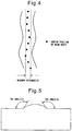
FIG. 4 is a view which shows a method of evaluation of offset of a bead. -
FIG. 5 is a view which shows a method of measurement of a toe angle of a bead. - Below, the content described in the claims will be explained more specifically to describe the advantageous effects of the present invention.
- The present invention and prior findings clearly differ in the point of clearly defining the content of CaO as described in (a) of
claim 1. When using a conventional fluoride-based FC.W by a direct current reverse polarity, welding in the vertical, overhead, and horizontal positions is not possible because the melting point of the slag is low, so a molten pool cannot be maintained at these welding positions. - As a measure against this, in the wire of the present invention, the high melting point substance CaO is contained as an essential ingredient. CaO is an oxide, but is a strongly basic substance. Even if contained in wire, the amount of oxygen of the weld metal is never remarkably increased. Further, the melting point of CaO is an extremely high temperature of about 2570°C, it is also possible to raise the melting point of the slag.
- If the content of CaO as a mass% with respect to the wire total mass is less than 0.2%, it is impossible to raise the melting point of the slag to an extent enabling welding in the vertical, overhead, and horizontal positions. Conversely, if more than 7.0% is contained, the slag melting point is too high, so solidification of the slag becomes faster and the fluidity of the slag cannot be secured, so slag inclusions easily occur.
- Further, if optimizing the timing of solidification of the slag, it is possible to suppress undercuts, when the content of CaO is made a mass% with respect to the wire total mass of 0.7% or more and 6.3% or less. Furthermore, to simultaneously obtain the spatter reducing effect and undercut inhibiting effect by arc stabilization, the content of CaO is made a mass% with respect to the wire total mass of 1.4% or more and 5.6% or less in range. According to the present invention the lower limit of CaO is made 1.7% or more and the upper limit of CaO is made 4.9% or less.
- Note that, when including a composite oxide such as CaO·SiO2 as the CaO, the content is calculated using the mass of only the CaO part.
- Next, addition of MgF2, CaF2, SrF2, and BaF2 will be explained.
- These fluorides are effective for raising the basicity of the slag and reducing the amount of oxygen of the weld metal. In addition, by these fluorides being contained along with CaO, the slag melting point can be adjusted to a suitable temperature. The melting point of CaO is an extremely high temperature of about 2570°C, but these four fluorides have melting points in the extremely close range of 1255°C to 1400°C, so one or more of these four fluorides may be contained.
- The total mass of the one or more of these four fluorides, to express this effect, has to be a mass% with respect to the wire total mass of 1.0% or more. Furthermore, the total mass of the one or more of MgF2, CaF2, SrF2, and BaF2 and the CaO has to be a mass% with respect to the wire total mass of 3.0% or more and 12.0% or less.
- The reason is that if the total mass is less than 3.0%, the content is too small and an amount of slag which is sufficient for maintaining a molten pool in the vertical, overhead, and horizontal positions cannot be obtained. Conversely, if over 12.0% is included, the arc stability can no longer be maintained and the molten pool becomes unstable in all positions, so the amount of generation of fumes becomes greater and the welding work environment is easily detrimentally affected.
- For this reason, the total mass of the one or more of MgF2, CaF2, SrF2, and BaF2 and the CaO is defined as 3.0% or more and 12.0% or less with respect to the wire total mass.
- Note that, if optimizing the total content of the one or more of MgF2, CaF2, SrF2, BaF2 and CaO, the arc stability is further improved and as a result the effect of stabilizing the bead width is obtained. From this viewpoint, the total content of the one or more of MgF2, CaF2, SrF2, and BaF2 and the CaO is preferably 4.0% or more and 10.0% or less with respect to the wire total mass. Further, in accordance with need, the lower limit may be made 5.0% or more and the upper limit may be made 9.0% or less.
- Next, the action of the metal elements having a deoxidizing action will be explained.
- It is known that the metal state Si, Al, Ti, Mg, Zr, Ca, Ce, and La all are elements which have powerful deoxidizing actions and are effective for reducing the oxygen in the weld metal. One or more of these elements are added in a mass% with respect to the wire total mass of 0.2% or more and 2.0% or less.
- However, regarding Al, if excessively contained in wire, formation of fine microstructures due to the intragranular transformation around Ti oxides is suppressed, so the toughness of the weld metal is degraded. For this reason, the content of Al is set to a mass% with respect to the wire total mass of less than 0.3%. In accordance with need, the content may be restricted to 0.2% or less or 0.1% or less.
- If the total mass of the one or more of Si, Al, Ti, Mg, Zr, Ca, Ce, and La is less than 0.2%, the content is too small and there is no effect on the reduction of the amount of oxygen of the weld metal. Further, if more than 2.0% is included, hard microstructures such as martensite-austenite constituents (hereinafter abbreviated as "MAC") easily form in the weld metal and the toughness of the weld metal is degraded.
- Therefore, the total mass of one or more of the metal states Si, Al, Ti, Mg, Zr, Ca, Ce, and La was made a mass% with respect to the wire total mass of 0.2% or more and 2.0% or less. The total mass may also be made, in accordance with need, a lower limit of 0.6% or more or 0.8% or more and an upper limit of 1.8% or less or 1.5% or less.
- Note that, these metal elements do not necessarily have to be pure metals (inclusion of unavoidable impurities is possible). There is no problem at all even if included in the form of an alloy such as Al-Mg. Note that, here, a deoxidation reaction during the welding is assumed, so Si, Al, Ti, Mg, Zr, Ca, Ce, and La are which are contained as oxides, fluorides, and carbonates are excluded. Further, whether these metal elements are contained in the steel sheath or contained in flux, the effect is the same, so inclusion in either the steel sheath or flux is possible.
- Next, the value of α defined by the following formula (1) will be explained.
- The present invention focuses on obtaining a weld metal with a high toughness, but an increase in toughness of the weld metal is not achieved by just the reduction of the oxygen. If the hardenability of the weld metal is not controlled to a suitable range, the weld metal comes to have coarse microstructures and hard microstructures. In this state, no matter how low the oxygen is reduced to, a high toughness weld metal cannot be obtained.
- From this viewpoint, the inventors proceeded to study typical elements having an effect on the hardenability of weld metal such as C, Si, Mn, Cu, Ni, Cr, Mo, V, Nb, and B by using the value of α which is shown by the following formula (1).
- As a result, it was learned that if the value of α is less than 0.15, the hardenability becomes insufficient, coarse grain boundary ferrite is formed, and the toughness of the weld metal is lowered. Conversely, if the value of α exceeds 0.40, the hardenability becomes excessive, the percentage of hard structures such as martensite increases, and the toughness of the weld metal deteriorates.
- Due to this reason, the conclusion was reached that the value of α which is defined in the following formula (1) has to be restricted to 0.15 or more and 0.40 or less in range. This range may, in accordance with need, be restricted to a lower limit of 0.18 or more or 0.20 or more and to an upper limit of 0.36 or less or 0.34 or less.

- Note that, in formula (1), since the hardenability of the weld metal is being discussed, elements which are included as oxides, fluorides, and carbonates are excluded. These elements may be included in similar forms as the above Si etc.
- Further, regarding P and S, these are widely known as harmful elements causing solidification cracks, a reduction in toughness, etc., so P and S are restricted to a total mass of a mass% with respect to the wire total mass of 0.040% or less. Note that, the total mass of P and S is preferably made as low as possible, but making the mass ratio with respect to the wire total mass 0.001% or less forces an excessive load on the refining step and remarkably impairs productivity, so this is not realistic. Therefore, the total mass of P and S does not have to be reduced to less than 0.001% with respect to the wire total mass.
- Next, the Si oxides, Mn oxides, Al oxides, Ti oxides, B oxides, and Zr oxides will be explained.
- It is known from research up to now that if these oxides are contained in the slag, the amount of oxygen of the weld metal increases. Therefore, to reduce the amount of oxygen of the weld metal, the content of these oxides is preferably kept as low as possible. However, these oxides have the effect of suppressing bead offset since when the weld bead is covered by slag, the uniformity of the covering is enhanced and the behavior of the molten pool is stabilized.
- Here, the inventors experimentally searched for the ranges of contents of these oxides by which the amount of oxygen of the weld metal can be stably reduced to 300 mass ppm or less. As a result, they discovered that if the total mass of the Si oxides, Mn oxides, Al oxides, Ti oxides, B oxides, and Zr oxides is a mass% with respect to the wire total mass of 0.2% or more and 3.0% or less, it is possible to suppress the amount of oxygen of the weld metal to 300 mass ppm or less and simultaneously realize the effect of suppression of bead offset.
- For the above reason, the total mass of Si oxides, Mn oxides, Al oxides, Ti oxides, B oxides, and Zr oxides has to be restricted to a mass% with respect to the wire total mass of 0.2% or more and 3.0% or less. Further, the total mass may, in accordance with need, be restricted to a lower limit of 0.5% or more or 0.7% or more and to an upper limit of 2.8% or less or 2.2% or less.
- Note that, when the oxides are composite oxides, for example, with Al2O3·SiO2, the masses of the corresponding parts are calculated by deeming the part of Al2O3 the Al oxides and deeming the part of SiO2 the Si oxides so as to find the total mass. The content of the Si oxides is defined as the SiO2 converted value, the content of the Mn oxides as the MnO2 converted value, the content of the Al oxides as the Al2O3 converted value, the content of the Ti oxides as the TiO2 converted value, the content of the B oxides as the B2O3 converted value, and the content of the Zr oxides as the ZrO2 converted value.
- Among the ingredients which are contained in the wire of the present invention, the balance other than the above ingredients consists of Fe, an arc stabilizer, and unavoidable impurities.
- Note that, the content of the iron powder in the flux which is filled in the steel sheath has to be a mass% with respect to the wire total mass of 5.0% or less. Improvement of the welding efficiency and improvement of the arc stability due to the inclusion of iron powder in the flux are known, but iron powder is a powder, so has a large surface area so sometimes the oxygen of the weld metal is increased by the extremely thin iron oxide which is inevitably formed on the iron powder surface.
- The inventors studied the content of the iron powder in the flux which can stably suppress the amount of oxygen of the weld metal to 300 ppm or less and as a result discovered that the content of the iron powder which is contained in the flux has to be a mass% with respect to the wire total mass of 5.0% or less. Further, they newly discovered that when making the content less than 3%, it is possible and more preferable to reduce the amount of oxygen of the weld metal down to 270 ppm or less.
- Further, the content of iron powder which is contained in the flux may be restricted to 4.0% or less or 2.4% or less in accordance with need.
- Further, when powder including Fe in the form of an alloy such as Fe-Si or Fe-Cr is included in the flux, the mass corresponding to the Fe in the alloy is added to the iron powder defined here.
- As the arc stabilizer, oxides, fluorides, carbonates, etc. including Li, Na, K, and Rb which are known in the prior art may be suitably selected for use. Further, the mass of the arc stabilizer is suitably made a mass ratio with respect to the wire total mass of 0.01% or more and 1.0% or less. A content in this range is preferable.
- The above was the basic constitution of the present invention. Due to this, reduction of the oxygen in the weld metal and flat, vertical, overhead, and horizontal welding can both be realized.
- Next, the means for further improving the characteristics of the welding wire of the present invention will be explained.
- First, CaCO3, MgCO3, SrCO3, and BaCO3 will be explained.
- These carbonates break down by the arc heat and generate carbon dioxide gas from the inside of the wire so have the effect of facilitate detachment of the molten droplets which are formed at the tip of the wire at the time of welding and make the molten droplets finer. For this reason, large grain molten droplets do not move to the molten pool, so in the spatter, it becomes possible in particular to reduce the large grain spatter. If large grain spatter deposits on the welded object, not only is the bead appearance degraded, but also the large grain spatter often is troublesome to remove. For this reason, the value of the effect of reduction of the large-grain spatter rate is great.
- To obtain this effect, the total content of one or more of CaCO3, MgCO3, SrCO3, and BaCO3 is preferably a mass% with respect to the wire total mass of 0.1% or more. Conversely, if the total content of one or more of CaCO3, MgCO3, SrCO3, and BaCO3 exceeds a mass% with respect to the wire total mass of 4.0%, the gas which is produced from inside the wire results in droplets of liquid being splattered from the tip of the wire resulting in a remarkable increase in the large size spatter.
- Due to the above reason, the total content of one or more of CaCO3, MgCO3, SrCO3, and BaCO3 is preferably a mass% with respect to the wire total mass of 0.1% or more and 4.0% or less. To greatly reduce the large-grain spatter rate, the lower limit is more preferably made 0.7% or more or 1.4% or more and the upper limit is more preferably made 3.6% or less or 2.3% or less.
- Note that, CaCO3, MgCO3, SrCO3, and BaCO3 are respectively, as shown in the following formula (2) to formula (5), substances which contain CaO, MgO, BaO, and SrO. When CaCO3, MgCO3, SrCO3, and BaCO3 are contained, the CaO, MgO, SrO, and BaO which are formed by heat decomposition are added to the contents of the above-mentioned CaO and later explained MgO, BaO, and SrO.
CaCO3→CaO+CO2 formula (2)
MgCO3→MgO+CO2 formula (3)
BaCO3→BaO+CO2 formula (4)
SrCO3→SrO+CO2 formula (5)
- Next, the advantageous effects of MgO, SrO, and BaO will be explained.
- MgO, SrO, and BaO act to reduce the viscosity of the slag, so have the effect of smoothening the toe of the weld bead and suppressing concentration of stress at a weld joint. To obtain this effect, inclusion by a mass% with respect to the wire total mass of 0.1% or more is necessary, but if the content is too great, the slag remarkably falls in viscosity, so the molten pool cannot be maintained in vertical, overhead, and horizontal welding and welding easily becomes impossible. For this reason, when including MgO, SrO, and BaO, the total content is preferably restricted to 0.1% or more and 3.2% or less with respect to the wire total mass. Further, the total content is, in accordance with need, restricted to a lower limit of 0.3% or more or 0.5% or more and to an upper limit of 2.7% or less or 2.0% or less.
- Next, an explanation of the steel sheath of the welding wire will be given.
- The wire of the present invention particularly preferably has no slit-shaped opening in the steel sheath causing moisture absorption. The flux which is used in the wire of the present invention contains a substance such as CaO, MgO, BaO, SrO, and fluorides which basically easily absorb moisture. For this reason, eliminating the slit-shaped opening causing moisture absorption is extremely useful from the viewpoint of preventing moisture absorption of the wire and stabilizing the quality of the welding wire. When there is a slit-shaped opening in the steel sheath, it is preferable to package the flux-cored wire in a container until right before use so as to suppress moisture absorption.
- Furthermore, from the viewpoint of reducing the diffusive hydrogen, the lubrication oil which is coated on the wire surface is preferably an oil not containing H such as perfluoro polyether.
- Note that, the diameter of the wire of the present invention is not particularly limited, but considering the welding efficiency and the wire productivity, 1.2 mm to 1.6 mm in range is preferable.
- Further, the total mass of the flux which is filled in the steel sheath is preferably a mass% with respect to the wire total mass (below, this value being referred to as the "flux filling rate") of 6.0% or more and 18.0% or less. The flux which is contained in the steel sheath is in a powder state. The flux is stabilized in position inside the wire by being held from the steel sheath. If the flux filling rate is less than 6.0%, the amount of flux which is present becomes too small for the space formed inside of the steel sheath and the strength of inclusion of the flux becomes weak. For this reason, there is a high possibility of the flux ending up moving inside the wire and the ingredients in the wire becoming unstable. Conversely, if the flux filling rate exceeds 18.0%, breakage frequently occurs in the drawing step at the time of wire production and the productivity is impaired, so this is not realistic. Due to the above reason, the flux filling rate is preferably 6.0% or more and 18.0% or less.
- Further, in the wire of the present invention, CaO, MgO, Si oxides, and Ti oxides are observed to tend to affect the slag peeling. From the viewpoint of expression of better slag peeling, in the mass ratio with respect to the wire total mass, the ratio of (CaO+MgO)/(Ti oxides+Si oxides) preferably exceeds 1.50.
- Below, examples will be used to explain the present invention and comparative examples.
- First, the steps of production of prototype wire will be explained. The steel sheath of the chemical composition which is shown in Table 1 is formed into a U-shape as shown in
FIG. 1 . At that stage, flux is filled inside the steel sheath from the top. After this, the sheath is formed into an O-shape. The resultant slitted wire is drawn to a prototype wire of a diameter of φ 1.2 mm by a drawing step. Further, a wire with no slit is formed by filling the steel sheath with flux, then welding together its seam so as to eliminate the slit-shaped opening in the steel sheet which causes absorption of moisture to the flux, then drawing the wire after this step to finish it to prototype wire of a diameter of φ1.2 mm. In the examples of the present invention, the ingredients of the wire were adjusted by the flux which is filled inside the steel sheath in all cases.Table 1 (mass%) C Si Mn P S Balance 0.03 0.10 0.50 0.007 0.005 Fe and unavoidable impurities - Using SM490B steel plate defined in JIS G 3106, grooves shown
FIG. 2 and FIG. 3 were formed and the above-mentioned prototype wires were welded at the flat, vertical, overhead, and horizontal welding positions and evaluated. The chemical composition of the SM490B steel material which is used for the tests are shown in Table 2. Further, the welding conditions at the welding positions are shown in Table 3, while the evaluated items of the prototype wires and passing standards are described in Table 4. Note that, in the examples, a gas of Ar+20%CO2 was used, but the wire of the present invention can be sufficiently used even if using a shield gas other than Ar+20%CO2 (for example, CO2 gas, He gas, or other generally used shield gas).Table 2 (mass%) C Si Mn P S Balance 0.15 0.20 1.10 0.007 0.007 Fe and unavoidable impurities Table 3 Welding positions Current (A) Voltage (V) Welding rate (cm/min) Shield gas Power supply polarity Flat 270 25 24 Ar+20%CO2 Direct current reverse polarity wire (+) Vertical 200 21 9 Ar+20%CO2 Direct current reverse polarity wire (+) Overhead 200 21 9 Ar+20%CO2 Direct current reverse polarity wire (+) Horizontal 250 24 28 Ar+20%CO2 Direct current reverse polarity wire (+) Table 4 Evaluated items and evaluation method Passing standard Test coverage Bead formation Visual judgment Wire nos. Evaluation method: Whether welds of 500 mm weld lengths are possible by grooves of different positions and whether test pieces for oxygen analysis tests and Charpy tests can be obtained from the weld metal. 1 to 124 149 to 155 Presence of weld defects Cases where no cracks or slag inclusions can be observed are judged as passing. Wire nos. Evaluation method: X-ray transmission and ultrasonic defect detection were used to confirm if there were cracks or slag inclusions in the weld metal. 1 to 124 In the table of test results, slag inclusions are abbreviated as "SI", cracks as "C", and blowholes as "BH". 149 to 155 Amount of oxygen of weld metal Cases where the amount of oxygen of the weld metal is 300 ppm or less are judged as passing. Wire nos. Evaluation method: A pin sample for analysis is taken from the weld metal, and the infrared absorption method is used for analysis of the amount of oxygen of the weld metal. 1 to 124 149 to 155 Toughness of weld metal Cases where three test pieces were tested at 0°C and Wire nos. Evaluation method: A 10 mm full size test piece was taken from the weld metal and measured by a Charpy impact test. the value of the absorbed energy was 200J oraverage more were judged as passing. 1 to 124 The table of test results describes the average values of three test pieces. 149 to 155 Depth of undercut Cases of a maximum depth of 0.5 mm or less were judged Wire nos. Evaluation method: Over the entire weld length of the surfacemost layer, the bead shape was measured three-dimensionally by a laser beam and the undercut depth measured. as passing. Further, cases of a maximum depth of 0.2 mm or less are judged as having an effect of improvement. 1 to 13 Occurrence of spatter Cases of 1.5 g/min or less were judged as passing. Wire nos. Evaluation method: Spatter produced per one minute arc time was trapped and the mass of the spatter was measured. Further, within 0.8 g/min, it is judged that an effect of imorovement of inhibition of spatter is observed. 1 to 13 Generation of fumes 1.0 g/min or less is deemed passing. wire nos. Evaluation method: Fumes produced per one minute arc time were trapped by filter paper and the change in mass of the filter paper was measured. 14 to 32 Stability of bead width Cases where the ratio of (minimum width of Wire nos. Evaluation method: Any bead at the surfacemost layer was selected and the bead width was measured. bead) / (maximum width of bead) was calculated and the value was 90% or more were judged as passing. Further, in case of 95% or more, it is judged that there is an effect of improvement of the bead width stability. 14 to 32 Presence of bead offset Cases where the value of Y defined by the left was 1 mm or less were judged as passing. Wire nos. Evaluation method: In the manner shown in FIG. 4 , the center of the bead width was measured at 10 points at equal intervals. The distance (Y) between the right-most point and the left-most point was measured.69 to 86 149 to 152 Rate of occurrence of large grain spatter Cases where the mass% with respect to the total spatter mass of the trapped mass of spatter which did not pass through a screen of 1 mm mesh was 20% or less were judged as passing. Further, in cases where this mass% was 10% or less, it was judged that there was an effect of reduction of large-grain spatter observed. Wire nos. Evaluation method: The total amount of spatter trapped per one minute arc time was sieved by a screen of 1 mm mesh. The mass of the spatter not passing through the screen was measured. 97 to 112 Bead toe angle Cases where the average value of the toe angles were 120° or more were judged as passing. Further, in cases where the average value of the toe angles was 150° or more, it was judged that an effect of smoothening the toe angle was observed. Wire nos. Evaluation method: As shown in FIG. 5 , the weld zone was cut and 10 cross-sectional test pieces were cut out. The toe angles at two locations of the two sides of the test pieces, for a total of 20 locations, were measured and the average value was used for evaluation.113 to 124 153 to 155 Diffusive hydrogen Cases of 5 ppm or less were judged as passing, while cases of 2 ppm or less were judged as having an effect of suppressing moisture absorption by the wire. Wire nos. Evaluation method: Diffusive hydrogen of the weld joint was measured based on the test method prescribed in JIS Z 3118. 1, 7, 11, 14, 20, 29, 33, 43, 53, 57, 61, 65, 69, 76, 79, 87, 91, 95, 97, 104, 111, 113, 118, 123, and125 to 148 Slag peeling Cases where slag naturally peeled off from the bead surface were evaluated as A and judged as passing. Wire nos. 113 to 124 Cases where slag peeled off from the bead surface by being struck several times and slag removal work was completed in within 30 seconds were evaluated as B and judged as passing. 153 to 155 Cases where peeling of slag was difficult and slag removal work required more than 30 seconds were evaluated as C and judged as not passing. Note
(1) Regarding all of the above evaluation tests, the bead part and the crater part within 50 mm from the welding start position are both excluded from evaluation as unstable regions.
(2) In the table of the test results, passing was indicated as "Good" and not passing as "Poor". - First, the content of CaO was examined using the wires of Wire Nos. 1 to 13 which are shown in Table 5. The test results are shown in Table 6 and Table 7.
- In Wire Nos. 1 to 11 where the content of CaO was a mass% with respect to the wire total mass of 0.2% or more and 7.0% or less, all wires were judged passing, that is, good results were obtained. Further, in Wire Nos. 2 to 10 where the content of CaO was a mass% with respect to the wire total mass of 0.7% or more and 6.3% or less, an undercut inhibiting effect was observed. Further, in Wire Nos. 3 to 9 where the content of CaO was a mass% with respect to the wire total mass of 1.4% or more and 5.6% or less, it was confirmed that effects of suppressing undercut and reducing spatter were simultaneously obtained.
Table 5 Class Wire no. Mass% with respect to wire total mass CaO MgF2 CaF2 SrF2 BaF2 Total content of MgF2, CaF2, SrF2, and BaF2 Total content of CaO, MgF2, CaF2, SrF2, and BaF2 Ref. ex. 1 0.2 1.0 1.0 1.0 1.5 4.5 4.7 Ref. ex. 2 0.7 4.5 0.0 0.0 0.0 4.5 5.2 Ref. ex. 3 1.4 0.0 4.5 0.0 0.0 4.5 5.9 Inv. ex. 4 2.1 0.0 0.0 4.5 0.0 4.5 6.6 Inv. ex. 5 2.8 0.0 0.0 0.0 4.5 4.5 7.3 Inv. ex. 6 3.5 0.0 3.0 0.0 1.5 4.5 8.0 Inv. ex. 7 4.2 1.5 0.0 3.0 0.0 4.5 8.7 Inv. ex. 8 4.9 2.0 1.0 1.0 0.5 4.5 9.4 Ref. ex. 9 5.6 1.0 2.0 0.5 1.0 4.5 10.1 Ref. ex. 10 6.3 0.5 1.0 1.0 2.0 4.5 10.8 Ref. ex. 11 7.0 1.0 0.5 2.0 1.0 4.5 11.5 Comp. ex. 12 0.1 1.0 1.0 1.0 1.5 4.5 4.6 Comp. ex. 13 7.1 1.0 1.0 1.0 1.5 4.5 11.6 - The ingredients other than the above were as follows. The units are mass% with respect to the wire total mass.


Table 6 Flat Class Wire no. Bead formation Weld defect Weld metal oxygen amount (ppm) Charpy test results (J) Undercut max. depth (mm) Spatter (g/min) Results of evaluation Ref. ex. 1 Good None 260 214 0.4 1.2 Good Ref. ex. 2 Good None 258 241 0.2 1.1 Good Ref. ex. 3 Good None 263 235 0.1 0.7 Good Inv. ex. 4 Good None 245 239 0.0 0.7 Good Inv. ex. 5 Good None 240 235 0.0 0.5 Good Inv. ex. 6 Good None 260 244 0.0 0.6 Good Inv. ex. 7 Good None 244 245 0.1 0.6 Good Inv. ex. 8 Good None 252 226 0.1 0.7 Good Ref. ex. 9 Good None 235 248 0.1 0.7 Good Ref. ex. 10 Good None 225 218 0.2 0.9 Good Ref. ex. 11 Good None 241 223 0.4 1.0 Good Comp. ex. 12 Good None 248 208 0.5 1.2 Good Comp. ex. 13 Good SI 366 123 0.5 1.2 Poor Vertical Class Wire no. Bead formation Weld defect Weld metal oxygen amount (ppm) Charpy test result s (J) Undercut max. depth (mm) Spatter (g/min) Results of evaluation Ref. ex. 1 Good None 245 236 0.3 1.4 Good Ref. ex. 2 Good None 231 225 0.1 1.3 Good Ref. ex. 3 Good None 263 247 0.1 0.7 Good Inv. ex. 4 Good None 248 230 0.0 0.7 Good Inv. ex. 5 Good None 257 215 0.0 0.6 Good Inv. ex. 6 Good None 265 238 0.0 0.6 Good Inv. ex. 7 Good None 240 240 0.1 0.7 Good Inv. ex. 8 Good None 266 247 0.1 0.6 Good Ref. ex. 9 Good None 240 228 0.2 0.7 Good Ref. ex. 10 Good None 239 238 0.1 1.1 Good Ref. ex. 11 Good None 244 236 0.4 1.3 Good Comp. ex. 12 Poor Welding not possible Poor Comp. ex. 13 Good SI 359 149 0.5 1.3 Poor Table 7 Overhead Class Wire no. Bead formation Weld defect Weld metal oxygen amount (ppm) Charpy test results (J) Undercut max. depth (mm) Spatter (g/min) Results of evaluation Ref. ex. 1 Good None 264 241 0.4 1.4 Good Ref. ex. 2 Good None 249 232 0.2 1.3 Good Ref. ex. 3 Good None 263 236 0.1 0.8 Good Inv. ex. 4 Good None 258 238 0.0 0.8 Good Inv. ex. 5 Good None 241 219 0.0 0.7 Good Inv. ex. 6 Good None 262 245 0.0 0.6 Good Inv. ex. 7 Good None 257 250 0.1 0.6 Good Inv. ex. 8 Good None 246 218 0.1 0.7 Good Ref. ex. 9 Good None 242 233 0.2 0.7 Good Ref. ex. 10 Good None 240 249 0.2 1.2 Good Ref. ex. 11 Good None 248 225 0.4 1.1 Good Comp. ex. 12 Poor Welding impossible Poor Comp. ex. 13 Good SI 377 177 0.5 1.3 Poor Horizontal Class Wire no. Bead formation Weld defect Weld metal oxygen amount (ppm) Charpy test results (J) Undercut max. depth (mm) Spatter (g/min) Results of evaluation Ref. ex. 1 Good None 249 223 0.4 1.2 Good Ref. ex. 2 Good None 251 231 0.2 1.3 Good Ref. ex. 3 Good None 255 236 0.1 0.7 Good Inv. ex. 4 Good None 248 222 0.0 0.7 Good Inv. ex. 5 Good None 265 235 0.0 0.7 Good Inv. ex. 6 Good None 246 218 0.0 0.6 Good Inv. ex. 7 Good None 239 221 0.1 0.6 Good Inv. ex. 8 Good None 254 213 0.1 0.6 Good Ref. ex. 9 Good None 249 229 0.2 0.7 Good Ref. ex. 10 Good None 237 209 0.1 1.3 Good Ref. ex. 11 Good None 240 211 0.4 1.2 Good Comp. ex. 12 Poor Welding impossible Poor Comp. ex. 13 Good SI 387 187 0.5 1.2 Poor - On the other hand, when using Wire No. 12 where the content of CaO was a mass% with respect to the wire total mass of 0.1%, the content of CaO was too small, so flat welding was possible, but at the other welding positions, dripping of the molten metal occurred and welding was impossible, so the result was judged not passing.
- Further, when using Wire No. 13 where the content of CaO was 7.1% by mass with respect to the wire total mass, the slag fluidity became insufficient and slag inclusions were observed in the weld metal, so the result was judged not passing.
- Next, the contents of CaO, MgF2, CaF2, SrF2, and BaF2 were examined using the wires described in Table 8. The test results are described in Table 9 and Table 10.
- In Wire Nos. 14 to 29 where the total content of MgF2, CaF2, SrF2, and BaF2 was 1.0% or more with respect to the wire total mass and the total content of MgF2, CaF2, SrF2, BaF2, and CaO was a mass% with respect to the wire total mass of 3.0% to 12.0%, all wires were judged to be passing, that is, good results were obtained.
Table 8 Class Wire no. Mass% with respect to wire total mass CaO MgF2 CaF2 SrF2 BaF2 Total of MgF2, CaF2,SrF2, BaF2 Total of MgF2, CaF2,SrF2, BaF2, CaO Inv. ex. 14 2.0 1.0 0.0 0.0 0.0 1.0 3.0 Inv. ex. 15 2.0 0.0 1.0 0.0 0.0 1.0 3.0 Inv. ex. 16 2.0 0.0 0.0 1.0 0.0 1.0 3.0 Inv. ex. 17 2.0 0.0 0.0 0.0 1.0 1.0 3.0 Inv. ex. 18 2.0 2.0 0.0 0.0 0.0 2.0 4.0 Inv. ex. 19 2.0 0.0 3.0 0.0 0.0 3.0 5.0 Inv. ex. 20 2.0 0.0 3.0 0.0 1.0 4.0 6.0 Inv. ex. 21 2.0 0.0 5.0 0.0 0.0 5.0 7.0 Inv. ex. 22 2.0 5.5 0.0 1.0 0.0 6.5 8.5 Inv. ex. 23 2.0 0.0 8.0 0.0 0.0 8.0 10.0 Inv. ex. 24 2.0 0.0 0.0 8.5 0.5 9.0 11.0 Inv. ex. 25 2.0 10.0 0.0 0.0 0.0 10.0 12.0 Inv. ex. 26 2.0 0.0 10.0 0.0 0.0 10.0 12.0 Inv. ex. 27 2.0 0.0 0.0 10.0 0.0 10.0 12.0 Inv. ex. 28 2.0 0.0 0.0 0.0 10.0 10.0 12.0 Inv. ex. 29 2.0 2.0 3.0 2.0 3.0 10.0 12.0 Comp. ex. 30 2.1 0.9 0.0 0.0 0.0 0.9 3.0 Comp. ex. 31 1.6 0.0 1.3 0.0 0.0 1.3 2.9 Comp. ex. 32 2.0 8.0 0.0 0.0 2.1 10.1 12.1 - The ingredients other than the above were as follows. The units are mass% with respect to the wire total mass.


Table 9 Flat Class Wire no. Bead formation Weld defect Weld metal oxygen amount (ppm) Charpy test results (J) Undercut max. depth (mm) Spatter (g/min) Results of evaluation Inv. ex. 14 Good None 244 258 0.7 92 Good Inv. ex. 15 Good None 253 247 0.8 93 Good Inv. ex. 16 Good None 257 269 0.6 93 Good Inv. ex. 17 Good None 269 264 0.6 93 Good Inv. ex. 18 Good None 256 255 0.7 96 Good Inv. ex. 19 Good None 267 259 0.6 97 Good Inv. ex. 20 Good None 260 267 0.7 98 Good Inv. ex. 21 Good None 245 249 0.7 96 Good Inv. ex. 22 Good None 255 228 0.6 97 Good Inv. ex. 23 Good None 261 238 0.7 97 Good Inv. ex. 24 Good None 247 255 0.6 94 Good Inv. ex. 25 Good None 254 245 0.7 92 Good Inv. ex. 26 Good None 244 266 0.7 93 Good Inv. ex. 27 Good None 248 245 0.7 93 Good Inv. ex. 28 Good None 250 239 0.6 93 Good Inv. ex. 29 Good None 266 230 0.7 92 Good Comp. ex. 30 Good SI 402 125 0.8 92 Poor Comp. ex. 31 Good None 245 250 0.8 91 Good Comp. ex. 32 Good None 256 238 1.2 92 Poor Overhead Class Wire no. Bead formation Weld defect Weld metal oxygen amount (ppm) Charpy test results (J) Undercut max. depth (mm) Spatter (g/min) Results of evaluation Inv. ex. 14 Good None 254 235 0.7 91 Good Inv. ex. 15 Good None 241 219 0.8 92 Good Inv. ex. 16 Good None 236 241 0.7 92 Good Inv. ex. 17 Good None 237 256 0.8 94 Good Inv. ex. 18 Good None 245 230 0.8 97 Good Inv. ex. 19 Good None 254 210 0.6 97 Good Inv. ex. 20 Good None 230 254 0.7 98 Good Inv. ex. 21 Good None 255 287 0.6 98 Good Inv. ex. 22 Good None 264 249 0.7 98 Good Inv. ex. 23 Good None 231 246 0.8 98 Good Inv. ex. 24 Good None 254 249 0.7 93 Good Inv. ex. 25 Good None 256 233 0.6 94 Good Inv. ex. 26 Good None 259 252 0.7 92 Good Inv. ex. 27 Good None 266 265 0.7 93 Good Inv. ex. 28 Good None 262 245 0.7 93 Good Inv. ex. 29 Good None 256 239 0.8 93 Good Comp. ex. 30 Good SI 379 158 0.9 92 Poor Comp. ex. 31 Poor Welding impossible Poor Comp. ex. 32 Good None 266 254 1.3 93 Poor Table 10 Vertical Class Wire no. Bead formation Weld defect Weld metal oxygen amount (ppm) Charpy test results (J) Undercut max. depth (mm) Spatter (g/min) Results of evaluation Inv. ex. 14 Good None 247 214 0.7 91 Good Inv. ex. 15 Good None 245 254 0.6 92 Good Inv. ex. 16 Good None 254 235 0.7 92 Good Inv. ex. 17 Good None 265 239 0.8 93 Good Inv. ex. 18 Good None 257 287 0.8 96 Good Inv. ex. 19 Good None 261 244 0.7 97 Good Inv. ex. 20 Good None 252 245 0.6 98 Good Inv. ex. 21 Good None 241 263 0.7 98 Good Inv. ex. 22 Good None 235 248 0.7 98 Good Inv. ex. 23 Good None 235 271 0.7 99 Good Inv. ex. 24 Good None 258 255 0.6 94 Good Inv. ex. 25 Good None 251 223 0.8 92 Good Inv. ex. 26 Good None 259 225 0.7 94 Good Inv. ex. 27 Good None 249 241 0.6 93 Good Inv. ex. 28 Good None 266 258 0.7 93 Good Inv. ex. 29 Good None 261 241 0.6 94 Good Comp. ex. 30 Good SI 357 148 0.6 93 Poor Comp. ex. 31 Poor Welding impossible Poor Comp. ex. 32 Good None 256 228 1.3 92 Poor Horizontal Class Wire no. Bead formation Weld defect Weld metal oxygen amount (ppm) Charpy test results (J) Undercut max. depth (mm) Spatter (g/min) Results of evaluation Inv. ex. 14 Good None 253 235 0.8 93 Good Inv. ex. 15 Good None 248 245 0.7 93 Good Inv. ex. 16 Good None 236 230 0.7 94 Good Inv. ex. 17 Good None 247 278 0.7 94 Good Inv. ex. 18 Good None 260 287 0.8 97 Good Inv. ex. 19 Good None 238 245 0.6 97 Good Inv. ex. 20 Good None 247 251 0.7 98 Good Inv. ex. 21 Good None 251 267 0.6 98 Good Inv. ex. 22 Good None 244 235 0.8 99 Good Inv. ex. 23 Good None 256 233 0.7 98 Good Inv. ex. 24 Good None 259 241 0.6 93 Good Inv. ex. 25 Good None 268 250 0.7 93 Good Inv. ex. 26 Good None 235 277 0.8 92 Good Inv. ex. 27 Good None 245 245 0.7 93 Good Inv. ex. 28 Good None 258 225 0.7 94 Good Inv. ex. 29 Good None 263 247 0.8 93 Good Comp. ex. 30 Good SI 361 147 0.8 93 Poor Comp. ex. 31 Poor Welding impossible Poor Comp. ex. 32 Good None 266 238 1.3 93 Poor - Further, in Wire Nos. 18 to 23 where the total content of MgF2, CaF2, SrF2, and BaF2 was 1.0% or more with respect to the wire total mass and where the total content of MgF2, CaF2, SrF2, BaF2, and CaO was a mass with respect to the wire total mass of 4.0% or more and 10.0% or less, the result was obtained that an effect of improvement of the bead width stability was obtained in addition to the above effects.
- On the other hand, in Wire No. 30 where the total content of MgF2, CaF2, SrF2, and BaF2 was less than 1.0% with respect to the wire total mass, the solidification temperature of the slag was too high, so the fluidity of the slag became insufficient, slag inclusions were observed in the weld metal, and not only that, the passing standards of the amount of oxygen of the weld metal and the results of the Charpy test failed to be met, so the wire was not passing.
- In Wire No. 31 where the total content of MgF2, CaF2, SrF2, BaF2, and CaO was less than 3.0% with respect to the wire total mass, the amount of slag was insufficient, so while flat welding was possible at other welding positions, the molten metal dripped and welding was impossible, so the wire was not passing.
- In Wire No. 32 where the total content of MgF2, CaF2, SrF2, BaF2, and CaO exceeded 12.0% with respect to the wire total mass, the amount of slag was excessive and the molten pool was unstable. As a result, the amount of generation of fumes at the time of welding did not meet the passing standards, so the wire was not passing.
- Next, the content of deoxidizing metal elements was examined using wires of Table 11. The test results are shown in Table 12 and Table 13.
- In Wire Nos. 33 to 53 where the content of Al was a mass% with respect to the wire total mass of less than 0.3% and where the total content of Si, Al, Ti, Mg, Zr, Ca, Ce, and La was a mass% with respect to the wire total mass of 0.2% or more and 2.0% or less, all wires were judged passing, that is, good results were obtained.
Table 11 Class Wire no. Mass% with respect to wire total mass Si Al Ti Mg Zr Ca Ce La Total of deoxidizing metal elements α Inv. ex. 33 0.2 0.0 0.0 0.0 0.0 0.0 0.0 0.0 0.2 0.34 Inv. ex. 34 0.1 0.1 0.0 0.0 0.0 0.0 0.0 0.0 0.2 0.34 Inv. ex. 35 0.1 0.0 0.1 0.0 0.0 0.0 0.0 0.0 0.2 0.34 Inv. ex. 36 0.1 0.0 0.0 0.1 0.0 0.0 0.0 0.0 0.2 0.34 Inv. ex. 37 0.1 0.0 0.0 0.0 0.1 0.0 0.0 0.0 0.2 0.34 Inv. ex. 38 0.1 0.0 0.0 0.0 0.0 0.1 0.0 0.0 0.2 0.34 Inv. ex. 39 0.1 0.0 0.0 0.0 0.0 0.0 0.1 0.0 0.2 0.34 Inv. ex. 40 0.1 0.0 0.0 0.0 0.0 0.0 0.0 0.1 0.2 0.34 Inv. ex. 41 0.3 0.0 0.1 0.1 0.0 0.0 0.0 0.1 0.6 0.34 Inv. ex. 42 0.4 0.1 0.1 0.3 0.0 0.0 0.0 0.1 1.0 0.35 Inv. ex. 43 0.5 0.0 0.1 0.4 0.0 0.0 0.0 0.0 1.0 0.35 Inv. ex. 44 0.1 0.2 0.1 0.2 0.3 0.2 0.1 0.3 1.5 0.34 Inv. ex. 45 0.3 0.0 0.1 0.1 0.8 0.2 0.0 0.3 1.8 0.34 Inv. ex. 46 2.0 0.0 0.0 0.0 0.0 0.0 0.0 0.0 2.0 0.40 Inv. ex. 47 0.1 0.0 1.9 0.0 0.0 0.0 0.0 0.0 2.0 0.34 Inv. ex. 48 0.1 0.0 0.0 1.9 0.0 0.0 0.0 0.0 2.0 0.34 Inv. ex. 49 0.1 0.0 0.0 0.0 1.9 0.0 0.0 0.0 2.0 0.34 Inv. ex. 50 0.1 0.0 0.0 0.0 0.0 1.9 0.0 0.0 2.0 0.34 Inv. ex. 51 0.1 0.0 0.0 0.0 0.0 0.0 1.9 0.0 2.0 0.34 Inv. ex. 52 0.1 0.0 0.0 0.0 0.0 0.0 0.0 1.9 2.0 0.34 Inv. ex. 53 0.3 0.2 0.3 0.2 0.3 0.2 0.3 0.2 2.0 0.34 Comp. ex. 54 0.1 0.3 0.1 0.2 0.3 0.0 0.1 0.3 1.4 0.34 comp. ex. 55 0.1 0.0 0.0 0.0 0.0 0.0 0.0 0.0 0.1 0.34 Comp. ex. 56 0.3 0.2 0.3 0.2 0.3 0.2 0.3 0.3 2.1 0.34 - The ingredients other than the above were as follows. The units are mass% with respect to the wire total mass.


Table 12 Flat Class Wire no. Bead formation Weld defect Weld metal oxygen amount (ppm) Charpy test results (J) Undercut max. depth (mm) Inv. ex. 33 Good None 258 207 Good Inv. ex. 34 Good None 268 213 Good Inv. ex. 35 Good None 259 220 Good Inv. ex. 36 Good None 268 205 Good Inv. ex. 37 Good None 261 214 Good Inv. ex. 38 Good None 258 220 Good Inv. ex. 39 Good None 267 231 Good Inv. ex. 40 Good None 250 267 Good Inv. ex. 41 Good None 241 247 Good Inv. ex. 42 Good None 233 256 Good Inv. ex. 43 Good None 230 255 Good Inv. ex. 44 Good None 226 241 Good Inv. ex. 45 Good None 220 239 Good Inv. ex. 46 Good None 217 254 Good Inv. ex. 47 Good None 215 258 Good Inv. ex. 48 Good None 216 244 Good Inv. ex. 49 Good None 218 289 Good Inv. ex. 50 Good None 210 278 Good Inv. ex. 51 Good None 217 269 Good Inv. ex. 52 Good None 205 270 Good Inv. ex. 53 Good None 219 265 Good Comp. ex. 54 Good None 240 156 Poor Comp. ex. 55 Good BH 323 189 Poor Comp. ex. 56 Good None 205 165 Poor Overhead Class Wire no. Bead formation Weld defect Weld metal oxygen amount (ppm) Charpy test results (J) Undercut max. depth (mm) Inv. ex. 33 Good None 265 209 Good Inv. ex. 34 Good None 268 217 Good Inv. ex. 35 Good None 245 222 Good Inv. ex. 36 Good None 255 216 Good Inv. ex. 37 Good None 269 218 Good Inv. ex. 38 Good None 256 220 Good Inv. ex. 39 Good None 255 231 Good Inv. ex. 40 Good None 264 214 Good Inv. ex. 41 Good None 256 245 Good Inv. ex. 42 Good None 247 261 Good Inv. ex. 43 Good None 230 256 Good Inv. ex. 44 Good None 224 266 Good Inv. ex. 45 Good None 220 272 Good Inv. ex. 46 Good None 218 285 Good Inv. ex. 47 Good None 214 285 Good Inv. ex. 48 Good None 210 260 Good Inv. ex. 49 Good None 204 280 Good Inv. ex. 50 Good None 209 278 Good Inv. ex. 51 Good None 210 269 Good Inv. ex. 52 Good None 214 264 Good Inv. ex. 53 Good None 220 271 Good Comp. ex. 54 Good None 240 145 Poor Comp. ex. 55 Good BH 354 172 Poor Comp. ex. 56 Good None 210 178 Poor Table 13 Vertical Class Wire no. Bead formation Weld defect Weld metal oxygen amount(pp m) Charpy test results (J) Undercut max. depth (mm) Inv. ex. 33 Good None 265 220 Good Inv. ex. 34 Good None 258 208 Good Inv. ex. 35 Good None 255 200 Good Inv. ex. 36 Good None 277 210 Good Inv. ex. 37 Good None 260 257 Good Inv. ex. 38 Good None 245 232 Good Inv. ex. 39 Good None 268 244 Good Inv. ex. 40 Good None 269 205 Good Inv. ex. 41 Good None 251 214 Good Inv. ex. 42 Good None 243 222 Good Inv. ex. 43 Good None 234 245 Good Inv. ex. 44 Good None 220 264 Good Inv. ex. 45 Good None 217 208 Good Inv. ex. 46 Good None 220 254 Good Inv. ex. 47 Good None 215 254 Good Inv. ex. 48 Good None 213 254 Good Inv. ex. 49 Good None 220 279 Good Inv. ex. 50 Good None 218 256 Good Inv. ex. 51 Good None 215 245 Good Inv. ex. 52 Good None 208 255 Good Inv. ex. 53 Good None 220 257 Good Comp. ex. 54 Good None 256 188 Poor Comp. ex. 55 Good BH 339 178 Poor Comp. ex. 56 Good None 198 166 Poor Horizontal Class Wire no. Bead formation Weld defect Weld metal oxygen amount (ppm) Charpy test results (J) Undercut max. depth (mm) Inv. ex. 33 Good None 264 220 Good Inv. ex. 34 Good None 255 208 Good Inv. ex. 35 Good None 268 200 Good Inv. ex. 36 Good None 263 210 Good Inv. ex. 37 Good None 266 257 Good Inv. ex. 38 Good None 259 232 Good Inv. ex. 39 Good None 261 244 Good Inv. ex. 40 Good None 266 205 Good Inv. ex. 41 Good None 251 214 Good Inv. ex. 42 Good None 243 222 Good Inv. ex. 43 Good None 230 236 Good Inv. ex. 44 Good None 226 254 Good Inv. ex. 45 Good None 220 258 Good Inv. ex. 46 Good None 214 254 Good Inv. ex. 47 Good None 210 254 Good Inv. ex. 48 Good None 217 254 Good Inv. ex. 49 Good None 211 278 Good Inv. ex. 50 Good None 214 256 Good Inv. ex. 51 Good None 205 265 Good Inv. ex. 52 Good None 211 267 Good Inv. ex. 53 Good None 209 281 Good Comp. ex. 54 Good None 243 154 Poor Comp. ex. 55 Good BH 335 181 Poor Comp. ex. 56 Good None 217 183 Poor - On the other hand, in Wire No. 54 where the content of Al was a mass% with respect to the wire total mass of 0.3%, fine structures resulting from intragranular transformation failed to be formed, so the toughness of the weld metal did not meet the passing standards, and the wire was not passing.
- Further, in Wire No. 55 where the total content of Si, Al, Ti, Mg, Zr, Ca, Ce, and La was a mass% with respect to the wire total mass of 0.1%, the deoxidation was insufficient, so blowholes formed and the wire was not passing.
- Further, in Wire No. 56 where the total content of Si, Al, Ti, Mg, Zr, Ca, Ce, and La was a mass% with respect to the wire total mass of 2.1%, hard microstructures such as MAC formed in the weld metal, so the Charpy test did not meet the passing standards and the wire was not passing.
- Next, as indicators of the content of alloy elements, the value of α and the total content of P and S were examined using the wires of Table 14. The test results are shown in Table 15.
- In Wire Nos. 57 to 65 where the value of α was 0.15% or more and 0.40% or less and where the total content of P and S was a mass% with respect to the wire total mass of 0.040% or less, all wires were judged passing, that is, good results were obtained.
Table 14 Class Wire no. Mass% with respect to wire total mass C Si Mn P S Cu Ni Cr Mo V Nb B α Total of P and S Total of deoxidizing metal ele-ments Inv. ex. 57 0.03 0.3 2.2 0.006 0.006 0.0 0.0 0.0 0.0 0.00 0.00 0.00 0.15 0.012 0.9 Inv. ex. 58 0.06 0.5 1.4 0.006 0.006 0.0 1.0 0.0 0.2 0.00 0.00 0.00 0.18 0.012 1.1 Inv. ex. 59 0.15 0.9 0.8 0.006 0.006 0.0 0.2 0.0 0.0 0.00 0.00 0.00 0.22 0.012 1.5 Inv. ex. 60 0.07 0.5 2.0 0.006 0.006 0.3 0.0 0.5 0.2 0.01 0.00 0.00 0.24 0.012 1.1 Inv. ex. 61 0.07 0.5 2.0 0.006 0.006 0.0 2.0 0.5 0.5 0.02 0.00 0.00 0.28 0.012 1.1 Inv. ex. 62 0.07 0.5 2.0 0.006 0.006 0.5 2.5 0.5 0.5 0.02 0.02 0.00 0.32 0.012 1.1 Inv. ex. 63 0.10 0.5 1.6 0.006 0.006 0.0 3.0 0.0 1.4 0.00 0.00 0.00 0.34 0.012 1.1 Inv. ex. 64 0.09 0.6 2.0 0.006 0.006 0.0 0.0 1.4 1.0 0.00 0.01 0.01 0.40 0.012 1.2 Inv. ex. 65 0.07 0.5 2.0 0.028 0.012 0.0 2.0 0.5 0.2 0.00 0.00 0.00 0.26 0.040 1.1 Comp. ex. 66 0.03 0.3 1.9 0.006 0.006 0.0 0.0 0.0 0.0 0.00 0.00 0.00 0.14 0.012 0.9 Comp. ex. 67 0.10 0.7 2.0 0.006 0.006 0.0 0.0 1.4 1.0 0.00 0.01 0.01 0.41 0.012 1.3 Comp. ex. 68 0.07 0.5 2.0 0.028 0.013 0.0 2.0 0.5 0.2 0.00 0.00 0.00 0.26 0.041 1.1 - The ingredients other than the above were as follows. The units are mass% with respect to the wire total mass.


- On the other hand, in Wire No. 66 where the value of α was 0.14, the hardenability was insufficient, so coarse microstructures such as grain boundary ferrite or ferrite side plates were formed and the toughness of the weld metal failed to meet the passing standard, so the wire was not passing.
- Further, in Wire No. 67 where the value of α was 0.41, the hardenability was excessive, so hard microstructures such as martensite formed and the toughness of the weld metal failed to meet the passing standard, so the wire was not passing.
- Further, in Wire No. 68 where the total content of P and S was a mass% with respect to the wire total mass of 0.041%, high temperature cracks occurred in the weld metal and the Charpy test also failed to meet the passing standard, so the wire was not passing.
- Next, the total content of Si oxides, Mn oxides, Al oxides, Ti oxides, B oxides, and Zr oxides was examined using the wires of Table 16. The results are shown in Table 17 and Table 18.
- In Wire Nos. 69 to 84 and 149 to 151 where the total content of Si oxides, Mn oxides, Al oxides, Ti oxides, B oxides, and Zr oxides was a mass% with respect to the wire total mass of 0.2% or more and 3.0% or less, all wires were judged passing, that is, good results were obtained.
Table 16 Class Wire nos. Mass% with respect to wire total mass Flux filling rate (mass%) Si oxides Mn oxides Al oxides Ti oxides B oxides Zr oxides Total of oxides Inv. ex. 69 0.2 0.0 0.0 0.0 0.0 0.0 0.2 12 Inv. ex. 70 0.0 0.2 0.0 0.0 0.0 0.0 0.2 12 Inv. ex. 71 0.0 0.0 0.2 0.0 0.0 0.0 0.2 12 Inv. ex. 72 0.0 0.0 0.0 0.2 0.0 0.0 0.2 12 Inv. ex. 73 0.0 0.0 0.0 0.0 0.2 0.0 0.2 12 Inv. ex. 74 0.0 0.2 0.2 0.0 0.1 0.0 0.5 12 Inv. ex. 75 0.1 0.3 0.2 0.1 0.0 0.0 0.7 13 Inv. ex. 76 0.8 0.0 0.0 0.1 0.1 0.0 1.0 13 Inv. ex. 77 0.0 0.0 1.0 0.0 0.5 0.0 1.5 13 Inv. ex. 78 0.4 0.6 0.4 0.4 0.4 0.0 2.2 14 Inv. ex. 79 0.7 0.5 0.7 0.7 0.3 0.0 2.9 15 Inv. ex. 80 3.0 0.0 0.0 0.0 0.0 0.0 3.0 15 Inv. ex. 81 0.0 3.0 0.0 0.0 0.0 0.0 3.0 15 Inv. ex. 82 0.0 0.0 3.0 0.0 0.0 0.0 3.0 15 Inv. ex. 83 0.0 0.0 0.0 3.0 0.0 0.0 3.0 15 Inv. ex. 84 0.0 0.0 0.0 0.0 3.0 0.0 3.0 15 Inv. ex. 149 0.0 0.0 0.0 0.0 0.0 0.2 0.2 12 Inv. ex. 150 0.0 0.0 0.0 0.0 0.0 3.0 3.0 15 Inv. ex. 151 0.5 0.0 0.7 0.1 0.0 0.2 1.5 13 Comp. ex. 85 0.1 0.0 0.0 0.0 0.0 0.0 0.1 12 Comp. ex. 86 0.7 0.4 0.8 0.7 0.5 0.0 3.1 15 Comp. ex. 152 0.7 0.4 0.8 0.2 0.5 0.5 3.1 15 - The ingredients other than the above were as follows. The units are mass% with respect to the wire total mass.


Table 17 Flat Class Wire no. Bead formation Weld defect Weld metal oxygen amount (ppm) Charpy test results (J) Bead offset (Y) (mm) Results of evaluation Inv. ex. 69 Good None 254 214 0.2 Good Inv. ex. 70 Good None 245 254 0.2 Good Inv. ex. 71 Good None 254 235 0.2 Good Inv. ex. 72 Good None 214 287 0.2 Good Inv. ex. 73 Good None 266 244 0.1 Good Inv. ex. 74 Good None 232 245 0.1 Good Inv. ex. 75 Good None 252 263 0.2 Good Inv. ex. 76 Good None 235 248 0.2 Good Inv. ex. 77 Good None 245 271 0.2 Good Inv. ex. 78 Good None 256 223 0.1 Good Inv. ex. 79 Good None 250 256 0.2 Good Inv. ex. 80 Good None 245 245 0.1 Good Inv. ex. 81 Good None 258 241 0.2 Good Inv. ex. 82 Good None 259 243 0.1 Good Inv. ex. 83 Good None 254 240 0.1 Good Inv. ex. 84 Good None 263 239 0.1 Good Inv. ex. 149 Good None 258 214 0.1 Good Inv. ex. 150 Good None 245 225 0.1 Good Inv. ex. 151 Good None 259 241 0.1 Good Comp. ex. 85 Good None 215 263 1.2 Poor Comp. ex. 86 Good None 366 123 0.3 Poor Comp. ex. 152 Good None 354 149 0.3 Poor Overhead Class Wire no. Bead formation Weld defects Weld metal oxygen amount (ppm) Charpy test results (J) Bead offset (Y) (mm) Results of evaluation Inv. ex. 69 Good None 255 214 0.2 Good Inv. ex. 70 Good None 249 254 0.1 Good Inv. ex. 71 Good None 263 235 0.1 Good Inv. ex. 72 Good None 241 287 0.2 Good Inv. ex. 73 Good None 243 244 0.2 Good Inv. ex. 74 Good None 262 245 0.1 Good Inv. ex. 75 Good None 230 263 0.2 Good Inv. ex. 76 Good None 244 214 0.2 Good Inv. ex. 77 Good None 260 254 0.1 Good Inv. ex. 78 Good None 254 235 0.1 Good Inv. ex. 79 Good None 239 239 0.2 Good Inv. ex. 80 Good None 265 241 0.3 Good Inv. ex. 81 Good None 248 236 0.2 Good Inv. ex. 82 Good None 246 247 0.1 Good Inv. ex. 83 Good None 262 241 0.1 Good Inv. ex. 84 Good None 241 252 0.1 Good Inv. ex. 149 Good None 269 209 0.1 Good Inv. ex. 150 Good None 268 236 0.1 Good Inv. ex. 151 Good None 244 225 0.1 Good Inv. ex. 153 Good None 260 211 0.1 Good Inv. ex. 154 Good None 271 225 0.1 Good Inv. ex. 155 Good None 243 217 0.1 Good Comp. ex. 85 Good None 255 279 1.3 Poor Comp. ex. 86 Good None 355 113 0.3 Poor Comp. ex. 152 Good None 335 147 0.3 Poor Table 18 Vertical Class Wire no. Bead formation Weld defects Weld metal oxygen amount (ppm) Charpy test results (J) Bead offset (Y) (mm) Results of evaluation Inv. ex. 69 Good None 245 214 0.2 Good Inv. ex. 70 Good None 231 254 0.1 Good Inv. ex. 71 Good None 259 235 0.2 Good Inv. ex. 72 Good None 257 287 0.1 Good Inv. ex. 73 Good None 265 244 0.1 Good Inv. ex. 74 Good None 247 245 0.1 Good Inv. ex. 75 Good None 259 263 0.2 Good Inv. ex. 76 Good None 240 248 0.2 Good Inv. ex. 77 Good None 239 271 0.1 Good Inv. ex. 78 Good None 255 214 0.1 Good Inv. ex. 79 Good None 245 254 0.2 Good Inv. ex. 80 Good None 254 235 0.2 Good Inv. ex. 81 Good None 249 239 0.1 Good Inv. ex. 82 Good None 255 256 0.1 Good Inv. ex. 83 Good None 263 237 0.1 Good Inv. ex. 84 Good None 261 235 0.2 Good Inv. ex. 149 Good None 247 225 0.1 Good Inv. ex. 150 Good None 265 247 0.1 Good Inv. ex. 151 Good None 257 230 0.1 Good Comp. ex. 85 Good None 262 270 1.3 Poor Comp. ex. 86 Good None 369 168 0.4 Poor Comp. ex. 152 Good None 369 177 0.3 Poor Horizontal Class Wire no. Bead formation Weld defects Weld metal oxygen amount (ppm) Charpy test results (J) Bead offset (Y) (mm) Results of evaluation Inv. ex. 69 Good None 249 214 0.2 Good Inv. ex. 70 Good None 251 254 0.2 Good Inv. ex. 71 Good None 255 235 0.1 Good Inv. ex. 72 Good None 241 287 0.1 Good Inv. ex. 73 Good None 246 244 0.2 Good Inv. ex. 74 Good None 232 245 0.2 Good Inv. ex. 75 Good None 254 263 0.2 Good Inv. ex. 76 Good None 258 214 0.2 Good Inv. ex. 77 Good None 245 254 0.2 Good Inv. ex. 78 Good None 254 235 0.1 Good Inv. ex. 79 Good None 252 239 0.2 Good Inv. ex. 80 Good None 261 245 0.1 Good Inv. ex. 81 Good None 244 223 0.1 Good Inv. ex. 82 Good None 263 218 0.2 Good Inv. ex. 83 Good None 231 231 0.1 Good Inv. ex. 84 Good None 246 229 0.2 Good Inv. ex. 149 Good None 258 241 0.1 Good Inv. ex. 150 Good None 247 258 0.1 Good Inv. ex. 151 Good None 268 277 0.1 Good Inv. ex. 153 Good None 262 225 0.1 Good Inv. ex. 154 Good None 240 235 0.1 Good Inv. ex. 155 Good None 254 249 0.1 Good Comp. ex. 85 Good None 248 277 1.3 Poor Comp. ex. 86 Good None 347 151 0.4 Poor Comp. ex. 152 Good None 388 142 0.3 Poor - On the other hand, in Wire No. 85 where the total content of the Si oxides, Mn oxides, Al oxides, Fe oxides, Ti oxides, B oxides, and Zr oxides was a mass% with respect to the wire total mass of 0.1%, the slag covering become uneven and the bead offset failed to satisfy the passing standard, so the wire was not passing.
- Further, in Wire Nos. 86 and 152 where the total content of Si oxides, Mn oxides, Al oxides, Ti oxides, B oxides, and Zr oxides was a mass% with respect to the wire total mass of 3.1%, the amount of oxygen of the weld metal and the Charpy test did not meet the passing standards, so the wires were not passing.
- Next, the content of iron powder which is contained in the flux was examined using the wires of Table 19. The test results are shown in Table 20 and Table 21.
- In Wire Nos. 87 to 95 where the content of the iron powder in the flux was a mass% with respect to the wire total mass of 5.0% or less, all of the wires were judged as passing, that is, good results were obtained.
Table 19 Class Wire Nos. Mass% with respect to wire total mass Flux filling rate (mass%) Content of iron powder in flux Ref. ex. 87 0.0 12 Ref. ex. 88 0.7 13 Ref. ex. 89 1.4 13 Ref. ex. 90 2.1 14 Ref. ex. 91 2.4 14 Ref. ex. 92 3.0 15 Ref. ex. 93 3.7 16 Ref. ex. 94 4.4 16 Ref. ex. 95 5.0 17 Comp. ex. 96 5.1 17 - The ingredients other than the above were as follows. The units are mass% with respect to the wire total mass.


Table 20 Flat Class Wire no. Bead formation Weld defect Weld metal oxygen amount (ppm) Charpy test results (J) Undercut max. depth (mm) Ref. ex. 87 Good None 230 302 Good Ref. ex. 88 Good None 241 289 Good Ref. ex. 89 Good None 244 274 Good Ref. ex. 90 Good None 250 251 Good Ref. ex. 91 Good None 254 243 Good Ref. ex. 92 Good None 271 231 Good Ref. ex. 93 Good None 279 225 Good Ref. ex. 94 Good None 281 235 Good Ref. ex. 95 Good None 294 230 Good Comp. ex. 96 Good None 315 186 Poor Overhead Class Wire no. Bead formation Weld defect Weld metal oxygen amount (ppm) Charpy test results (J) Undercut max. depth (mm) Ref. ex. 87 Good None 231 214 Good Ref. ex. 88 Good None 245 254 Good Ref. ex. 89 Good None 250 235 Good Ref. ex. 90 Good None 258 239 Good Ref. ex. 91 Good None 265 287 Good Ref. ex. 92 Good None 273 244 Good Ref. ex. 93 Good None 278 245 Good Ref. ex. 94 Good None 278 263 Good Ref. ex. 95 Good None 289 214 Good Comp. ex. 96 Good None 322 171 Poor Table 21 Vertical Class Wire no. Bead formation Weld defect Weld metal oxygen amount (ppm) Charpy test results (J) Undercut max. depth (mm) Ref. ex. 87 Good None 232 214 Good Ref. ex. 88 Good None 239 254 Good Ref. ex. 89 Good None 241 235 Good Ref. ex. 90 Good None 248 239 Good Ref. ex. 91 Good None 259 287 Good Ref. ex. 92 Good None 274 244 Good Ref. ex. 93 Good None 279 245 Good Ref. ex. 94 Good None 288 263 Good Ref. ex. 95 Good None 295 248 Good Comp. ex. 96 Good None 328 179 Poor Horizontal Class Wire no. Bead formation Weld defect Weld metal oxygen amount (ppm) Charpy test results (J) Undercut max. depth (mm) Ref. ex. 87 Good None 235 214 Good Ref. ex. 88 Good None 241 254 Good Ref. ex. 89 Good None 249 235 Good Ref. ex. 90 Good None 250 239 Good Ref. ex. 91 Good None 256 287 Good Ref. ex. 92 Good None 271 244 Good Ref. ex. 93 Good None 275 245 Good Ref. ex. 94 Good None 280 263 Good Ref. ex. 95 Good None 297 214 Good Comp. ex. 96 Good None 317 188 Poor - On the other hand, in Wire No. 96 where the content of the iron powder in the flux is a mass% with respect to the wire total mass of 5.1%, the amount of oxygen of the weld metal and the results of the Charpy test did not meet the passing standards, so the result was not passing.
- Next, the total content of CaCO3, MgCO3, SrCO3, and BaCO3 was examined using the wires of Table 22. The results are shown in Table 23 and Table 24.
- In Wire Nos. 98 to 111 where the total content of CaCO3, MgCO3, SrCO3, and BaCO3 was a mass% with respect to the wire total mass of 0.1% or more and 4.0% or less, all of the wires were passing. An effect of improvement suppressing the large-grain spatter rate could be confirmed. Further, in Wire No. 97 where CaCO3, MgCO3, SrCO3, and BaCO3 were not contained as well, the wire was passing.
Table 22 Class Wire Nos. Mass% with respect to wire total mass CaCO3 BaCO3 SrCO3 MgCO3 Total content of carbonates CaO content formed by heat decomposition BaO content formed by heat decomposition SrO content formed by heat decomposition MgO content formed by heat decomposition Total content of CaO, MgF2, CaF2, SrF2, BaF2 (*1) Total content of MgO, BaO, SrO, (*1) Inv. ex. 97 0.0 0.0 0.0 0.0 0.0 0.0 0.0 0.0 0.0 5.6 0.0 Inv. ex. 98 0.1 0.0 0.0 0.0 0.1 0.1 0.0 0.0 0.0 5.7 0.0 Inv. ex. 99 0.0 0.1 0.0 0.0 0.1 0.0 0.1 0.0 0.0 5.6 0.1 Inv. ex. 100 0.0 0.0 0.1 0.0 0.1 0.0 0.0 0.1 0.0 5.6 0.1 Inv. ex. 101 0.0 0.0 0.0 0.1 0.1 0.0 0.0 0.0 0.0 5.6 0.0 Inv. ex. 102 0.3 0.2 0.0 0.2 0.7 0.2 0.2 0.0 0.1 5.8 0.3 Inv. ex. 103 0.7 0.3 0.2 0.2 1.4 0.4 0.2 0.1 0.1 6.0 0.5 Inv. ex. 104 0.5 1.3 0.5 0.0 2.3 0.3 1.0 0.4 0.0 5.9 1.4 Inv. ex. 105 0.0 0.5 0.9 1.6 3.0 0.0 0.4 0.6 0.8 5.6 1.8 Inv. ex. 106 1.8 0.6 1.2 0.0 3.6 1.0 0.5 0.8 0.0 6.6 1.3 Inv. ex. 107 4.0 0.0 0.0 0.0 4.0 2.2 0.0 0.0 0.0 7.8 0.0 Inv. ex. 108 0.0 4.0 0.0 0.0 4.0 0.0 3.1 0.0 0.0 5.6 3.1 Inv. ex. 109 0.0 0.0 4.0 0.0 4.0 0.0 0.0 2.8 0.0 5.6 2.8 Inv. ex. 110 0.0 0.0 0.0 4.0 4.0 0.0 0.0 0.0 1.9 5.6 1.9 Inv. ex. 111 1.5 1.4 0.7 0.4 4.0 0.8 1.1 0.5 0.2 6.4 1.8 Comp. ex. 112 1.5 1.5 0.7 0.4 4.1 0.8 1.2 0.5 0.2 6.4 1.9 *1: Sum of mass arising due to heat decomposition of carbonates - The ingredients other than the above were as follows. The units are mass% with respect to the wire total mass.


Table 23 Flat Class Wire no. Bead formation Weld defect Weld metal oxygen amount (ppm) Charpy test results (J) Spatter (g/min) Large-grain spatter rate (%) Results of evaluation Inv. ex. 97 Good None 245 220 0.8 15 Good Inv. ex. 98 Good None 244 208 0.7 7 Good Inv. ex. 99 Good None 266 205 0.8 7 Good Inv. ex. 100 Good None 237 204 0.8 8 Good Inv. ex. 101 Good None 220 222 0.7 6 Good Inv. ex. 102 Good None 235 208 0.7 7 Good Inv. ex. 103 Good None 225 200 0.7 7 Good Inv. ex. 104 Good None 265 210 0.8 6 Good Inv. ex. 105 Good None 261 257 0.8 5 Good Inv. ex. 106 Good None 242 232 0.8 6 Good Inv. ex. 107 Good None 252 244 0.8 5 Good Inv. ex. 108 Good None 245 245 0.8 6 Good Inv. ex. 109 Good None 259 236 0.8 7 Good Inv. ex. 110 Good None 256 241 0.7 8 Good Inv. ex. 111 Good None 258 247 0.7 7 Good Comp. ex. 112 Good None 247 240 2.1 25 Poor Overhead Class Wire no. Bead formation Weld defect Weld metal oxygen amount (ppm) Charpy test results (J) Spatter (g/min) Large-grain spatter rate (%) Results of evaluation Inv. ex. 97 Good None 260 220 0.7 17 Good Inv. ex. 98 Good None 249 208 0.8 6 Good Inv. ex. 99 Good None 263 200 0.8 6 Good Inv. ex. 100 Good None 268 210 0.8 7 Good Inv. ex. 101 Good None 241 257 0.7 6 Good Inv. ex. 102 Good None 251 232 0.6 4 Good Inv. ex. 103 Good None 262 244 0.7 6 Good Inv. ex. 104 Good None 230 205 0.8 6 Good Inv. ex. 105 Good None 242 214 0.8 6 Good Inv. ex. 106 Good None 244 222 0.8 6 Good Inv. ex. 107 Good None 248 208 0.8 7 Good Inv. ex. 108 Good None 257 249 0.7 8 Good Inv. ex. 109 Good None 245 251 0.8 9 Good Inv. ex. 110 Good None 235 253 0.7 8 Good Inv. ex. 111 Good None 244 287 0.7 8 Good Comp. ex. 112 Good None 253 240 2.3 22 Poor Table 24 Vertical Class Wire no. Bead formation Weld defect Weld metal oxygen amount (ppm) Charpy test results (J) Spatter (g/min) Large-grain spatter rate (%) Results of evaluation Inv. ex. 97 Good None 244 253 0.8 16 Good Inv. ex. 98 Good None 231 254 0.8 9 Good Inv. ex. 99 Good None 263 235 0.7 6 Good Inv. ex. 100 Good None 248 239 0.8 8 Good Inv. ex. 101 Good None 257 287 0.8 8 Good Inv. ex. 102 Good None 265 244 0.7 9 Good Inv. ex. 103 Good None 241 245 0.8 7 Good Inv. ex. 104 Good None 263 263 0.7 8 Good Inv. ex. 105 Good None 240 248 0.7 7 Good Inv. ex. 106 Good None 239 271 0.7 8 Good Inv. ex. 107 Good None 253 223 0.6 7 Good Inv. ex. 108 Good None 255 245 0.7 9 Good Inv. ex. 109 Good None 240 236 0.8 7 Good Inv. ex. 110 Good None 252 240 0.7 9 Good Inv. ex. 111 Good None 263 241 0.8 8 Good Comp. ex. 112 Good None 257 249 2.3 29 Poor Horizontal Class Wire no. Bead formation Weld defect Weld metal oxygen amount (ppm) Charpy test results (J) Spatter (g/min) Large-grain spatter rate (%) Results of evaluat ion Inv. ex. 97 Good None 249 214 0.9 14 Good Inv. ex. 98 Good None 251 254 0.8 8 Good Inv. ex. 99 Good None 255 235 0.8 6 Good Inv. ex. 100 Good None 248 239 0.4 7 Good Inv. ex. 101 Good None 263 287 0.4 5 Good Inv. ex. 102 Good None 246 244 0.4 5 Good Inv. ex. 103 Good None 242 245 0.7 6 Good Inv. ex. 104 Good None 254 263 0.8 7 Good Inv. ex. 105 Good None 249 248 0.8 5 Good Inv. ex. 106 Good None 237 2.71 0.8 7 Good Inv. ex. 107 Good None 240 223 0.8 6 Good Inv. ex. 108 Good None 236 256 0.8 6 Good Inv. ex. 109 Good None 241 255 0.7 7 Good Inv. ex. 110 Good None 252 248 0.8 8 Good Inv. ex. 111 Good None 261 243 0.7 7 Good Comp. ex. 112 Good None 247 240 2.3 24 Poor - On the other hand, in Wire No. 112 where the total content of CaCO3, MgCO3, SrCO3, and BaCO3 was a mass% with respect to the wire total mass of 4.1%, the content was excessive, so the wire did not satisfy the passing standards for both the total amount of spatter and the large-grain spatter ratio and was not passing.
- Next, the content of MgO, BaO, and SrO was examined using the wires of Table 25. The results are shown in Table 26 and Table 27.
- In Wire Nos. 114 to 123 where the content of MgO, BaO, and SrO was a mass% with respect to the wire total mass of 0.1% or more and 3.2% or less, the wires were all passing. An effect of smoothening the bead toe angles could also be confirmed. Further, in Wire No. 113 where MgO was not contained in the wire as well, the wire was judged passing.
- Further, in Wire No. 117 and Wire Nos. 120 to 123 where the ratio of content of (CaO+MgO)/(Si oxides+Ti oxides) exceeded 1.50, an effect of improvement of slag peeling was confirmed and welding work became easier as a result.
Table 25 Class Wire Nos. Mass% with respect to wire total mass MgO BaO SrO Total content of MgO, BaO, SrO (CaO+MgO) (Si oxides+Ti oxides) Inv. ex. 113 0.0 0.0 0.0 0.0 1.21 Inv. ex. 114 0.1 0.0 0.0 0.1 1.29 Inv. ex. 115 0.0 0.1 0.0 0.1 1.21 Inv. ex. 116 0.0 0.0 0.1 0.1 1.21 Inv. ex. 117 3.2 0.0 0.0 3.2 3.50 Inv. ex. 118 0.0 3.2 0.0 3.2 1.21 Inv. ex. 119 0.0 0.0 3.2 3.2 1.21 Inv. ex. 120 0.5 0.0 0.0 0.5 1.57 Inv. ex. 121 1.0 0.7 0.3 2.0 1.93 Inv. ex. 122 0.8 1.3 0.6 2.7 1.79 Inv. ex. 123 0.9 0.5 1.8 3.2 1.86 Comp. ex. 124 3.3 0.0 0.0 3.3 3.57 Comp. ex. 153 0.0 3.3 0.0 3.3 1.21 Comp. ex. 154 0.0 0.0 3.3 3.3 1.21 Comp. ex. 155 0.9 0.6 1.8 3.3 1.86 - The ingredients other than the above were as follows. The units are mass% with respect to the wire total mass.


Table 26 Flat Class Wire no. Bead formation Weld defect Bead toe angle (°) Weld metal oxygen amount (ppm) Charpy test results (J) Slag peeling Results of evaluation Inv. ex. 113 Good None 135 245 214 B Good Inv. ex. 114 Good None 156 262 254 B Good Inv. ex. 115 Good None 154 254 235 B Good Inv. ex. 116 Good None 159 235 239 B Good Inv. ex. 117 Good None 155 245 287 A Good Inv. ex. 118 Good None 154 269 244 B Good Inv. ex. 119 Good None 157 252 245 B Good Inv. ex. 120 Good None 158 250 263 A Good Inv. ex. 121 Good None 160 235 248 A Good Inv. ex. 122 Good None 155 239 271 A Good Inv. ex. 123 Good None 159 255 223 A Good Comp. ex. 124 Good None 155 261 247 A Good Comp. ex. 153 Good None 153 258 244 B Good Comp. ex. 154 Good None 158 259 240 B Good Comp. ex. 155 Good None 157 266 251 A Good Overhead Class Wire no. Bead formation Weld defect Bead toe angle (°) Weld metal oxygen amount (ppm) Charpy test results (J) Slag peeling Results of evaluation Inv. ex. 113 Good None 141 265 214 B Good Inv. ex. 114 Good None 154 249 254 B Good Inv. ex. 115 Good None 159 263 235 B Good Inv. ex. 116 Good None 153 268 239 B Good Inv. ex. 117 Good None 159 241 287 A Good Inv. ex. 118 Good None 160 241 244 B Good Inv. ex. 119 Good None 161 262 245 B Good Inv. ex. 120 Good None 162 240 263 A Good Inv. ex. 121 Good None 159 242 248 A Good Inv. ex. 122 Good None 157 254 271 A Good Inv. ex. 123 Good None 153 248 223 A Good Comp. ex. 124 Poor Welding impossible Poor Comp. ex. 153 Poor Welding impossible Poor Comp. ex. 154 Poor Welding impossible Poor Comp. ex. 155 Poor Welding impossible Poor Table 27 Vertical Class Wire no. Bead formation Weld defect Bead toe angle (°) Weld metal oxygen amount (ppm) Charpy test results (J) Slag peeling Results of evaluation Inv. ex. 113 Good None 133 245 214 B Good Inv. ex. 114 Good None 160 231 254 B Good Inv. ex. 115 Good None 161 263 235 B Good Inv. ex. 116 Good None 160 248 239 B Good Inv. ex. 117 Good None 158 257 287 A Good Inv. ex. 118 Good None 159 265 244 B Good Inv. ex. 119 Good None 165 268 245 B Good Inv. ex. 120 Good None 160 261 263 A Good Inv. ex. 121 Good None 155 240 248 A Good Inv. ex. 122 Good None 157 239 271 A Good Inv. ex. 123 Good None 153 244 223 A Good Comp. ex. 124 Poor Welding impossible Poor Comp. ex. 153 Poor Welding impossible Poor Comp. ex. 154 Poor Welding impossible Poor Comp. ex. 155 Poor Welding impossible Poor Horizontal Class Wire no. Bead formation Weld defect Bead toe angle (°) Weld metal oxygen amount (ppm) Charpy test results (J) Slag peeling Results of evaluation Inv. ex. 113 Good None 136 249 214 B Good Inv. ex. 114 Good None 156 251 254 B Good Inv. ex. 115 Good None 154 255 235 B Good Inv. ex. 116 Good None 158 248 239 B Good Inv. ex. 117 Good None 157 263 287 A Good Inv. ex. 118 Good None 152 246 244 B Good Inv. ex. 119 Good None 151 252 245 B Good Inv. ex. 120 Good None 160 254 263 A Good Inv. ex. 121 Good None 162 249 248 A Good Inv. ex. 122 Good None 154 237 271 A Good Inv. ex. 123 Good None 157 240 223 A Good Comp. ex. 124 Poor Welding impossible Poor Comp. ex. 153 Poor Welding impossible Poor Comp. ex. 154 Poor Welding impossible Poor Comp. ex. 155 Poor Welding impossible Poor - On the other hand, in Wire Nos. 124 and 153 to 155 where the content of MgO, BaO, and SrO was a mass% with respect to the wire total mass of 3.3%, the content was excessive, so welding was not possible. Since welding was impossible in the vertical, overhead, and horizontal positions, the wire was not passing.
- Finally, the slit of the steel sheath was examined using the wires of Table 28. That is, prototype wires of the wire numbers at the left side of Table 28 and prototype wires of the wire numbers of the right side of Table 28 which differ in only the point of the existence of a slit-shaped opening which causes absorption of moisture at the steel sheath were produced and evaluated for diffusive hydrogen. The results are shown in Table 29.
- In both wires with a slit at the steel sheath and wires with no slit at the steel sheath, the wires were all passing, so in wires with no slit at the steel sheath, a clear effect of reduction of diffusive hydrogen could be observed.

-
Table 29 Flat Class Wire no. Diffusive hydrogen (ppm) Results of evaluation Ref. ex. 1 5 Good Inv. ex. 7 4 Good Ref. ex. 11 5 Good Inv. ex. 14 5 Good Inv. ex. 19 4 Good Inv. ex. 26 5 Good Inv. ex. 30 5 Good Inv. ex. 39 4 Good Inv. ex. 50 5 Good Inv. ex. 54 4 Good Inv. ex. 58 5 Good Inv. ex. 61 5 Good Inv. ex. 66 4 Good Inv. ex. 73 5 Good Inv. ex. 81 4 Good Inv. ex. 86 5 Good Inv. ex. 90 5 Good Inv. ex. 94 4 Good Inv. ex. 96 4 Good Inv. ex. 103 5 Good Inv. ex. 110 4 Good Inv. ex. 112 4 Good Inv. ex. 117 5 Good Inv. ex. 122 4 Good Ref. ex. 125 2 Good Inv. ex. 126 2 Good Ref. ex. 127 1 Good Inv. ex. 128 2 Good Inv. ex. 129 2 Good Inv. ex. 130 2 Good Inv. ex. 131 1 Good Inv. ex. 132 2 Good Inv. ex. 133 1 Good Inv. ex. 134 2 Good Inv. ex. 135 2 Good Inv. ex. 136 2 Good Inv. ex. 137 2 Good Inv. ex. 138 1 Good Inv. ex. 139 2 Good Ref. ex. 140 2 Good Ref. ex. 141 2 Good Ref. ex. 142 2 Good Inv. ex. 143 1 Good Inv. ex. 144 2 Good Inv. ex. 145 2 Good Inv. ex. 146 2 Good Inv. ex. 147 1 Good Inv. ex. 148 2 Good - The test results of the examples which were explained above are shown together in Table 30 as results of overall evaluation.
Table 30 Claim Verified items Class Wire nos. Flat Vertical Horizontal Overhead Results of overall evaluation Content of CaO Inventive and Reference ex. 1-11 Good Good Good Good Good Comp. ex. 12 Good Poor Poor Poor Poor 13 Poor Poor Poor Poor Poor Total content of CaO and MgF2, CaF2, SrF2, BaF2 Inv. ex. 14-29 Good Good Good Good Good Comp. ex. 30 Poor Poor Poor Poor Poor Comp. ex. 31 Good Poor Poor Poor Poor Comp. ex. 32 Poor Poor Poor Poor Poor Deoxidizing metal elements Inv. ex. 33-53 Good Good Good Good Good 1 Comp. ex. 54-56 Poor Poor Poor Poor Poor value of α and contents of P and S Inv. ex. 57-65 Good Good Good Good Good Comp. ex. 66-68 Poor Poor Poor Poor Poor Total content of Si oxides, Mn oxides, Al oxides, Zr oxides Ti oxides, B oxides Inv. ex. 69-84 149-151 Good Good Good Good Good Comp. ex. 85-86 152 Poor Poor Poor Poor Poor Content of iron powder in flux Ref. ex. 87-95 Good Good Good Good Good Comp. ex. 96 Poor Poor Poor Poor Poor 2 Content of carbonates Inv. ex. 97-111 Good Good Good Good Good Comp. ex. 112 Poor Poor Poor Poor Poor 3 Content of MgO, BaO, SrO Inv. ex. 113-123 Good Good Good Good Good Comp. ex. 124, 153-155 Good Poor Poor Poor Poor 4 Steel sheath slit Inv. ex. 125-148 Good Good Good Good Good
Claims (4)
- A flux-cored wire for gas shielded arc welding use comprised of a steel sheath which is filled with a flux, said flux-cored wire for gas shielded arc welding use characterized by simultaneously satisfying the conditions of the following (a) to (f):(a) CaO is contained in a mass% with respect to a wire total mass of 1.7% or more and 4.9% or less.(b) One or more of MgF2, CaF2, SrF2, and BaF2 is contained, a total of the content is a mass% with respect to the wire total mass of 1.0% or more, and a total of one or more of MgF2, CaF2, SrF2, and BaF2 and CaO is a mass% with respect to the wire total mass of 3.0% or more and 12.0% or less.(c) One or more of a metal state Si, Al, Ti, Mg, Zr, Ca, Ce, and La is contained, a total of the content is, with respect to the wire total mass, 0.2% or more and 2.0% or less, and a range of content of metal state Al is limited to a mass% with respect to the wire total mass of less than 0.3%.(d) A value of α which is defined by the following formula (1) is 0.15 or more and 0.40 or less in range and a total of the contents of P and S is limited to a mass% with respect to the wire total mass of 0.040% or less.
 (e) A total of contents of Si oxides, Mn oxides, Al oxides, Ti oxides, B oxides, and Zr oxides is a mass% with respect to the wire total mass of 0.2% or more and 3.0% or less.(f) A balance of Fe, an arc stabilizer, and unavoidable impurities, and a content of iron powder in the flux is a mass% with respect to the wire total mass of 5.0% or less.
 - A flux-cored wire for gas shielded arc welding use as set forth in claim 1 characterized in that, further, one or more of CaCO3, MgCO3, SrCO3, and BaCO3 is contained and in that the total of the contents is a mass% with respect to the wire total mass of 0.1% or more and 4.0% or less.
- A flux-cored wire for gas shielded arc welding use as set forth in claim 1 or 2 characterized in that, further, one or more of MgO, SrO, and BaO is contained and in that the total of the contents is a mass% with respect to the wire total mass of 0.1% or more and 3.2% or less.
- A flux-cored wire for gas shielded arc welding use as set forth in any one of claim 1 to claim 3 characterized in that there is no slit-shaped opening causing absorption of moisture in said steel sheath.
Applications Claiming Priority (2)
| Application Number | Priority Date | Filing Date | Title |
|---|---|---|---|
| JP2009285230 | 2009-12-16 | ||
| PCT/JP2010/072834 WO2011074689A1 (en) | 2009-12-16 | 2010-12-14 | Wire containing flux for gas-sealed arc welding, allowing all-position welding |
Publications (3)
| Publication Number | Publication Date |
|---|---|
| EP2489461A1 EP2489461A1 (en) | 2012-08-22 |
| EP2489461A4 EP2489461A4 (en) | 2014-12-31 |
| EP2489461B1 true EP2489461B1 (en) | 2016-04-13 |
Family
ID=44167439
Family Applications (1)
| Application Number | Title | Priority Date | Filing Date |
|---|---|---|---|
| EP10837713.6A Not-in-force EP2489461B1 (en) | 2009-12-16 | 2010-12-14 | Wire containing flux for gas-sealed arc welding, allowing all-position welding |
Country Status (7)
| Country | Link |
|---|---|
| US (1) | US9211613B2 (en) |
| EP (1) | EP2489461B1 (en) |
| JP (1) | JP4834191B2 (en) |
| KR (1) | KR101193273B1 (en) |
| CN (1) | CN102655978B (en) |
| TW (1) | TW201130594A (en) |
| WO (1) | WO2011074689A1 (en) |
Families Citing this family (30)
| Publication number | Priority date | Publication date | Assignee | Title |
|---|---|---|---|---|
| TW201318756A (en) * | 2011-11-01 | 2013-05-16 | Sorex Welding Co Ltd | Submerged arc material for heat resistant steel |
| KR101535399B1 (en) * | 2012-05-08 | 2015-07-08 | 신닛테츠스미킨 카부시키카이샤 | Flux-containing wire for welding ultrahigh-tensile steel |
| JP5825210B2 (en) * | 2012-07-09 | 2015-12-02 | 新日鐵住金株式会社 | Pulse gas shielded arc welding method |
| CN102773631B (en) * | 2012-08-09 | 2015-05-20 | 上海电力修造总厂有限公司 | Core wire and coating of nuclear-grade nickel base covered electrode of basic slag system, covered electrode and preparation methods |
| EP2952288B1 (en) * | 2013-01-31 | 2018-09-05 | Nippon Steel & Sumitomo Metal Corporation | Flux cored wire, welding method using flux cored wire, method for producing welded joint using flux cored wire, and welded joint |
| US9700964B2 (en) * | 2013-03-15 | 2017-07-11 | Lincoln Global, Inc. | Boric acid free flux |
| JP6365063B2 (en) * | 2013-07-29 | 2018-08-01 | 新日鐵住金株式会社 | High toughness flux shielded wire for gas shielded arc welding with excellent vertical welding workability |
| JP6221628B2 (en) * | 2013-10-25 | 2017-11-01 | 新日鐵住金株式会社 | Box pillar manufacturing method |
| JP6252104B2 (en) * | 2013-10-25 | 2017-12-27 | 新日鐵住金株式会社 | Box pillar manufacturing method |
| KR101674743B1 (en) * | 2013-11-08 | 2016-11-09 | 신닛테츠스미킨 카부시키카이샤 | Flux-cored wire for gas-shielded arc welding, method for welding steel for very low temperature use, and method for manufacturing weld joint |
| WO2015068261A1 (en) * | 2013-11-08 | 2015-05-14 | 新日鐵住金株式会社 | Method for producing weld joint |
| CN103962743B (en) * | 2014-04-30 | 2016-02-24 | 西安理工大学 | For welding wire that X100 pipe line steel full position welds and preparation method thereof |
| JP6382117B2 (en) * | 2015-01-16 | 2018-08-29 | 日鐵住金溶接工業株式会社 | Flux-cored wire for Ar-CO2 mixed gas shielded arc welding |
| JP6437327B2 (en) * | 2015-01-28 | 2018-12-12 | 日鐵住金溶接工業株式会社 | Flux-cored wire for carbon dioxide shielded arc welding |
| US11426821B2 (en) * | 2015-02-25 | 2022-08-30 | Hobart Brothers Llc | Aluminum metal-cored welding wire |
| US20160318115A1 (en) * | 2015-05-01 | 2016-11-03 | Lincoln Global, Inc. | Welding process |
| CN104942475B (en) * | 2015-07-10 | 2017-06-16 | 北京工业大学 | A kind of X90/X100 pipe line steels high intensity metallic core welding wire for submerged-arc welding and preparation method thereof |
| JP6453178B2 (en) * | 2015-07-17 | 2019-01-16 | 株式会社神戸製鋼所 | Flux-cored wire for gas shielded arc welding |
| JP2017094360A (en) | 2015-11-25 | 2017-06-01 | 日鐵住金溶接工業株式会社 | Flux-cored wire for shield-arc welding using argon-carbon dioxide gas mixture |
| JP6766866B2 (en) * | 2016-03-08 | 2020-10-14 | 日本製鉄株式会社 | Flux-cored wire, welded joint manufacturing method, and welded joint |
| US10946486B2 (en) | 2016-03-08 | 2021-03-16 | Nippon Steel Corporation | Flux-cored wire, manufacturing method of welded joint, and welded joint |
| JP6726008B2 (en) * | 2016-03-25 | 2020-07-22 | 株式会社神戸製鋼所 | Flux-cored wire for gas shield arc welding |
| JP6762131B2 (en) * | 2016-04-28 | 2020-09-30 | 株式会社神戸製鋼所 | Flux-cored wire |
| CN106181122B (en) * | 2016-08-10 | 2018-12-25 | 中国船舶重工集团公司第七二五研究所 | A kind of seamless submerged arc flux-cored wire for yield strength 550MPa steel |
| CN106346166A (en) * | 2016-08-31 | 2017-01-25 | 晋城市金菲机电有限公司 | Low-temperature preheating high-strength flux-cored wire and production process thereof |
| US11400539B2 (en) | 2016-11-08 | 2022-08-02 | Nippon Steel Corporation | Flux-cored wire, manufacturing method of welded joint, and welded joint |
| CN110315240A (en) * | 2018-03-29 | 2019-10-11 | 株式会社神户制钢所 | Flux-cored wire |
| JP7231476B2 (en) * | 2019-05-09 | 2023-03-01 | 株式会社神戸製鋼所 | FLUX CORE WIRE, WELDING METHOD AND WELD METAL |
| CN110900034B (en) * | 2019-12-17 | 2021-08-24 | 天津市永昌焊丝有限公司 | All-position alkaline flux-cored wire |
| JP7440303B2 (en) * | 2020-03-06 | 2024-02-28 | 株式会社神戸製鋼所 | Flux for electroslag welding and electroslag welding method |
Family Cites Families (30)
| Publication number | Priority date | Publication date | Assignee | Title |
|---|---|---|---|---|
| JPS5149581B1 (en) * | 1965-11-15 | 1976-12-27 | ||
| US3542998A (en) * | 1967-06-07 | 1970-11-24 | Air Reduction | Cored electrode for welding in air |
| GB1336182A (en) * | 1970-04-24 | 1973-11-07 | Airco Inc | Cored consumable electrode for stainless steel welding |
| US4149063A (en) * | 1977-03-28 | 1979-04-10 | The International Nickel Company, Inc. | Flux cored wire for welding Ni-Cr-Fe alloys |
| JPS57137094A (en) * | 1981-02-17 | 1982-08-24 | Kawasaki Steel Corp | High speed submerged arc welding method of single layer on both sides |
| US4571480A (en) * | 1984-02-27 | 1986-02-18 | Kabushiki Kaisha Kobe Seiko Sho | Flux cored wire electrodes for self-shielded arc welding |
| JPS62151293A (en) * | 1985-12-26 | 1987-07-06 | Kobe Steel Ltd | Flux cored wire for gas shielded arc welding |
| JPH02207996A (en) * | 1989-02-08 | 1990-08-17 | Nippon Steel Corp | Flux cored wire electrode for gas shielded arc welding |
| JP2687006B2 (en) | 1989-02-18 | 1997-12-08 | 新日本製鐵株式会社 | Flux-cored wire for gas shielded arc welding for refractory steel |
| US5055655A (en) * | 1989-09-11 | 1991-10-08 | The Lincoln Electric Company | Low hydrogen basic metal cored electrode |
| US5171958A (en) * | 1990-08-16 | 1992-12-15 | Kawasaki Steel Corporation | High-efficiency fillet welding method for steel plate |
| JP2500020B2 (en) | 1992-03-31 | 1996-05-29 | 株式会社神戸製鋼所 | Basic flux-cored wire for gas shield arc welding |
| JP3203527B2 (en) | 1993-02-15 | 2001-08-27 | 新日本製鐵株式会社 | Flux-cored wire for gas shielded arc welding |
| EP0652071A1 (en) * | 1993-08-12 | 1995-05-10 | Kabushiki Kaisha Kobe Seiko Sho | Flux-cored wire for gas shield arc welding with low fume |
| JP3377271B2 (en) | 1993-12-10 | 2003-02-17 | 新日本製鐵株式会社 | Flux-cored wire for gas shielded arc welding |
| JPH07276088A (en) | 1994-04-04 | 1995-10-24 | Nippon Steel Corp | Mag welding flux cored wire for low temperature steel |
| CN1117903A (en) | 1994-08-30 | 1996-03-06 | 天津大学 | Low alloy steel high-toughness self-shielded flux-cored welding stick |
| JP3464334B2 (en) * | 1996-03-19 | 2003-11-10 | 日鐵住金溶接工業株式会社 | Flux-cored wire for gas shielded arc welding used for fillet welding of primer-coated steel sheets |
| CA2231985C (en) * | 1997-03-26 | 2004-05-25 | Sumitomo Metal Industries, Ltd. | Welded high-strength steel structures and methods of manufacturing the same |
| JPH10296486A (en) * | 1997-05-02 | 1998-11-10 | Nippon Steel Corp | Flux cored wire for welding 9% nickel steel |
| JP3586362B2 (en) | 1997-08-22 | 2004-11-10 | 株式会社神戸製鋼所 | Flux-cored wire for gas shielded arc welding |
| JP2001205482A (en) | 2000-01-19 | 2001-07-31 | Nippon Steel Weld Prod & Eng Co Ltd | Flux-containing wire for gas shield arc welding |
| US6784401B2 (en) * | 2001-01-30 | 2004-08-31 | Illinois Tool Works Inc. | Welding electrode and method for reducing manganese in fume |
| JP3758040B2 (en) * | 2002-07-26 | 2006-03-22 | 株式会社神戸製鋼所 | Flux-cored wire for gas shielded arc welding for low alloy heat resistant steel |
| FR2866825B1 (en) * | 2004-03-01 | 2007-04-20 | Air Liquide | HEXAVALENT SMOKE AND LOW SMOKE EMITTED ELECTRODE FOR STAINLESS STEEL WELDING |
| US7812284B2 (en) * | 2005-07-12 | 2010-10-12 | Lincoln Global, Inc. | Barium and lithium ratio for flux cored electrode |
| US20070051702A1 (en) * | 2005-09-08 | 2007-03-08 | Lincoln Global, Inc., A Delaware Corporation | Flux system to reduce copper cracking |
| US8153934B2 (en) * | 2006-09-15 | 2012-04-10 | Lincoln Global, Inc. | Saw flux system for improved as-cast weld metal toughness |
| JP5097499B2 (en) | 2006-10-19 | 2012-12-12 | 株式会社神戸製鋼所 | Flux-cored wire for gas shielded arc welding for low alloy heat resistant steel |
| JP5387192B2 (en) * | 2009-07-16 | 2014-01-15 | 新日鐵住金株式会社 | Flux-cored wire for gas shield welding |
-
2010
- 2010-12-14 WO PCT/JP2010/072834 patent/WO2011074689A1/en active Application Filing
- 2010-12-14 JP JP2011524042A patent/JP4834191B2/en active Active
- 2010-12-14 EP EP10837713.6A patent/EP2489461B1/en not_active Not-in-force
- 2010-12-14 US US13/513,904 patent/US9211613B2/en not_active Expired - Fee Related
- 2010-12-14 CN CN201080056957.8A patent/CN102655978B/en not_active Expired - Fee Related
- 2010-12-14 KR KR1020127014896A patent/KR101193273B1/en active IP Right Grant
- 2010-12-15 TW TW099143978A patent/TW201130594A/en not_active IP Right Cessation
Also Published As
| Publication number | Publication date |
|---|---|
| TWI372089B (en) | 2012-09-11 |
| EP2489461A4 (en) | 2014-12-31 |
| US20120241433A1 (en) | 2012-09-27 |
| KR101193273B1 (en) | 2012-10-19 |
| CN102655978A (en) | 2012-09-05 |
| KR20120084780A (en) | 2012-07-30 |
| EP2489461A1 (en) | 2012-08-22 |
| WO2011074689A1 (en) | 2011-06-23 |
| JPWO2011074689A1 (en) | 2013-05-02 |
| TW201130594A (en) | 2011-09-16 |
| JP4834191B2 (en) | 2011-12-14 |
| US9211613B2 (en) | 2015-12-15 |
| CN102655978B (en) | 2015-08-05 |
Similar Documents
| Publication | Publication Date | Title |
|---|---|---|
| EP2489461B1 (en) | Wire containing flux for gas-sealed arc welding, allowing all-position welding | |
| US20220281024A1 (en) | Flux-cored wire, manufacturing method of welded joint, and welded joint | |
| KR101674743B1 (en) | Flux-cored wire for gas-shielded arc welding, method for welding steel for very low temperature use, and method for manufacturing weld joint | |
| JP6291461B2 (en) | Flux-cored wire for gas shielded arc welding | |
| EP3020504A1 (en) | Flux-cored wire for build-up welding | |
| EP3208030B1 (en) | Flux-cored wire for arc welding of duplex stainless steel | |
| KR102013984B1 (en) | Flux-cored wire for gas-shielded arc welding | |
| JP6891630B2 (en) | Flux-cored wire for gas shielded arc welding and welding joint manufacturing method | |
| EP3444063A2 (en) | Electrodes for forming austenitic and duplex steel weld metal | |
| RU2707763C1 (en) | Welding method using a special welding torch | |
| JP6365063B2 (en) | High toughness flux shielded wire for gas shielded arc welding with excellent vertical welding workability | |
| JP6953870B2 (en) | Flux-cored wire for gas shielded arc welding and welding joint manufacturing method | |
| WO2020012925A1 (en) | Flux-cored wire for two-phase stainless steel welding, welding method and welding metal | |
| JP6257489B2 (en) | Gas shield arc welding method | |
| EP4056312A1 (en) | Fluxed core wire and method for manufacturing weld joint | |
| JP2020015092A (en) | Flux-cored wire for welding two-phase stainless steel, welding method and weld metal | |
| JP4881512B2 (en) | Flux-cored wire for self-shielded arc welding | |
| JPS6357155B2 (en) | ||
| JPH0669634B2 (en) | Self-shielded arc welding flux-cored wire for thin plates | |
| KR20230162714A (en) | Manufacturing method of flux cored wire and welded joints | |
| JPH0818154B2 (en) | Self-shielded arc welding flux-cored wire for thin plates | |
| JPH0832373B2 (en) | Gas shielded arc welding flux cored wire | |
| JPH04309493A (en) | Flux cored wire for gas shielded arc welding | |
| JPS6284892A (en) | Ion powder compound flux cored wire |
Legal Events
| Date | Code | Title | Description |
|---|---|---|---|
| PUAI | Public reference made under article 153(3) epc to a published international application that has entered the european phase |
Free format text: ORIGINAL CODE: 0009012 |
|
| 17P | Request for examination filed |
Effective date: 20120515 |
|
| AK | Designated contracting states |
Kind code of ref document: A1 Designated state(s): AL AT BE BG CH CY CZ DE DK EE ES FI FR GB GR HR HU IE IS IT LI LT LU LV MC MK MT NL NO PL PT RO RS SE SI SK SM TR |
|
| RAP1 | Party data changed (applicant data changed or rights of an application transferred) |
Owner name: NIPPON STEEL & SUMITOMO METAL CORPORATION |
|
| DAX | Request for extension of the european patent (deleted) | ||
| A4 | Supplementary search report drawn up and despatched |
Effective date: 20141202 |
|
| RIC1 | Information provided on ipc code assigned before grant |
Ipc: B23K 35/30 20060101ALI20141126BHEP Ipc: B23K 35/02 20060101ALI20141126BHEP Ipc: B23K 35/368 20060101AFI20141126BHEP |
|
| GRAP | Despatch of communication of intention to grant a patent |
Free format text: ORIGINAL CODE: EPIDOSNIGR1 |
|
| INTG | Intention to grant announced |
Effective date: 20151006 |
|
| GRAS | Grant fee paid |
Free format text: ORIGINAL CODE: EPIDOSNIGR3 |
|
| GRAA | (expected) grant |
Free format text: ORIGINAL CODE: 0009210 |
|
| RIN1 | Information on inventor provided before grant (corrected) |
Inventor name: SHIMURA, RYUICHI Inventor name: SASAKI, KIYOHITO Inventor name: KOJIMA, KAZUHIRO |
|
| AK | Designated contracting states |
Kind code of ref document: B1 Designated state(s): AL AT BE BG CH CY CZ DE DK EE ES FI FR GB GR HR HU IE IS IT LI LT LU LV MC MK MT NL NO PL PT RO RS SE SI SK SM TR |
|
| REG | Reference to a national code |
Ref country code: GB Ref legal event code: FG4D |
|
| REG | Reference to a national code |
Ref country code: AT Ref legal event code: REF Ref document number: 789592 Country of ref document: AT Kind code of ref document: T Effective date: 20160415 Ref country code: CH Ref legal event code: EP |
|
| REG | Reference to a national code |
Ref country code: IE Ref legal event code: FG4D |
|
| REG | Reference to a national code |
Ref country code: DE Ref legal event code: R096 Ref document number: 602010032342 Country of ref document: DE |
|
| REG | Reference to a national code |
Ref country code: SE Ref legal event code: TRGR |
|
| REG | Reference to a national code |
Ref country code: LT Ref legal event code: MG4D |
|
| REG | Reference to a national code |
Ref country code: AT Ref legal event code: MK05 Ref document number: 789592 Country of ref document: AT Kind code of ref document: T Effective date: 20160413 |
|
| REG | Reference to a national code |
Ref country code: NL Ref legal event code: MP Effective date: 20160413 |
|
| PG25 | Lapsed in a contracting state [announced via postgrant information from national office to epo] |
Ref country code: LT Free format text: LAPSE BECAUSE OF FAILURE TO SUBMIT A TRANSLATION OF THE DESCRIPTION OR TO PAY THE FEE WITHIN THE PRESCRIBED TIME-LIMIT Effective date: 20160413 Ref country code: NO Free format text: LAPSE BECAUSE OF FAILURE TO SUBMIT A TRANSLATION OF THE DESCRIPTION OR TO PAY THE FEE WITHIN THE PRESCRIBED TIME-LIMIT Effective date: 20160713 Ref country code: PL Free format text: LAPSE BECAUSE OF FAILURE TO SUBMIT A TRANSLATION OF THE DESCRIPTION OR TO PAY THE FEE WITHIN THE PRESCRIBED TIME-LIMIT Effective date: 20160413 Ref country code: FI Free format text: LAPSE BECAUSE OF FAILURE TO SUBMIT A TRANSLATION OF THE DESCRIPTION OR TO PAY THE FEE WITHIN THE PRESCRIBED TIME-LIMIT Effective date: 20160413 Ref country code: NL Free format text: LAPSE BECAUSE OF FAILURE TO SUBMIT A TRANSLATION OF THE DESCRIPTION OR TO PAY THE FEE WITHIN THE PRESCRIBED TIME-LIMIT Effective date: 20160413 |
|
| REG | Reference to a national code |
Ref country code: FR Ref legal event code: PLFP Year of fee payment: 7 |
|
| PG25 | Lapsed in a contracting state [announced via postgrant information from national office to epo] |
Ref country code: ES Free format text: LAPSE BECAUSE OF FAILURE TO SUBMIT A TRANSLATION OF THE DESCRIPTION OR TO PAY THE FEE WITHIN THE PRESCRIBED TIME-LIMIT Effective date: 20160413 Ref country code: AT Free format text: LAPSE BECAUSE OF FAILURE TO SUBMIT A TRANSLATION OF THE DESCRIPTION OR TO PAY THE FEE WITHIN THE PRESCRIBED TIME-LIMIT Effective date: 20160413 Ref country code: HR Free format text: LAPSE BECAUSE OF FAILURE TO SUBMIT A TRANSLATION OF THE DESCRIPTION OR TO PAY THE FEE WITHIN THE PRESCRIBED TIME-LIMIT Effective date: 20160413 Ref country code: LV Free format text: LAPSE BECAUSE OF FAILURE TO SUBMIT A TRANSLATION OF THE DESCRIPTION OR TO PAY THE FEE WITHIN THE PRESCRIBED TIME-LIMIT Effective date: 20160413 Ref country code: PT Free format text: LAPSE BECAUSE OF FAILURE TO SUBMIT A TRANSLATION OF THE DESCRIPTION OR TO PAY THE FEE WITHIN THE PRESCRIBED TIME-LIMIT Effective date: 20160816 Ref country code: RS Free format text: LAPSE BECAUSE OF FAILURE TO SUBMIT A TRANSLATION OF THE DESCRIPTION OR TO PAY THE FEE WITHIN THE PRESCRIBED TIME-LIMIT Effective date: 20160413 Ref country code: GR Free format text: LAPSE BECAUSE OF FAILURE TO SUBMIT A TRANSLATION OF THE DESCRIPTION OR TO PAY THE FEE WITHIN THE PRESCRIBED TIME-LIMIT Effective date: 20160714 |
|
| PG25 | Lapsed in a contracting state [announced via postgrant information from national office to epo] |
Ref country code: BE Free format text: LAPSE BECAUSE OF FAILURE TO SUBMIT A TRANSLATION OF THE DESCRIPTION OR TO PAY THE FEE WITHIN THE PRESCRIBED TIME-LIMIT Effective date: 20160413 |
|
| REG | Reference to a national code |
Ref country code: DE Ref legal event code: R097 Ref document number: 602010032342 Country of ref document: DE |
|
| PG25 | Lapsed in a contracting state [announced via postgrant information from national office to epo] |
Ref country code: CZ Free format text: LAPSE BECAUSE OF FAILURE TO SUBMIT A TRANSLATION OF THE DESCRIPTION OR TO PAY THE FEE WITHIN THE PRESCRIBED TIME-LIMIT Effective date: 20160413 Ref country code: EE Free format text: LAPSE BECAUSE OF FAILURE TO SUBMIT A TRANSLATION OF THE DESCRIPTION OR TO PAY THE FEE WITHIN THE PRESCRIBED TIME-LIMIT Effective date: 20160413 Ref country code: SK Free format text: LAPSE BECAUSE OF FAILURE TO SUBMIT A TRANSLATION OF THE DESCRIPTION OR TO PAY THE FEE WITHIN THE PRESCRIBED TIME-LIMIT Effective date: 20160413 Ref country code: RO Free format text: LAPSE BECAUSE OF FAILURE TO SUBMIT A TRANSLATION OF THE DESCRIPTION OR TO PAY THE FEE WITHIN THE PRESCRIBED TIME-LIMIT Effective date: 20160413 Ref country code: DK Free format text: LAPSE BECAUSE OF FAILURE TO SUBMIT A TRANSLATION OF THE DESCRIPTION OR TO PAY THE FEE WITHIN THE PRESCRIBED TIME-LIMIT Effective date: 20160413 |
|
| PLBE | No opposition filed within time limit |
Free format text: ORIGINAL CODE: 0009261 |
|
| STAA | Information on the status of an ep patent application or granted ep patent |
Free format text: STATUS: NO OPPOSITION FILED WITHIN TIME LIMIT |
|
| PG25 | Lapsed in a contracting state [announced via postgrant information from national office to epo] |
Ref country code: SM Free format text: LAPSE BECAUSE OF FAILURE TO SUBMIT A TRANSLATION OF THE DESCRIPTION OR TO PAY THE FEE WITHIN THE PRESCRIBED TIME-LIMIT Effective date: 20160413 |
|
| 26N | No opposition filed |
Effective date: 20170116 |
|
| PG25 | Lapsed in a contracting state [announced via postgrant information from national office to epo] |
Ref country code: SI Free format text: LAPSE BECAUSE OF FAILURE TO SUBMIT A TRANSLATION OF THE DESCRIPTION OR TO PAY THE FEE WITHIN THE PRESCRIBED TIME-LIMIT Effective date: 20160413 |
|
| REG | Reference to a national code |
Ref country code: CH Ref legal event code: PL |
|
| PG25 | Lapsed in a contracting state [announced via postgrant information from national office to epo] |
Ref country code: MC Free format text: LAPSE BECAUSE OF FAILURE TO SUBMIT A TRANSLATION OF THE DESCRIPTION OR TO PAY THE FEE WITHIN THE PRESCRIBED TIME-LIMIT Effective date: 20160413 |
|
| REG | Reference to a national code |
Ref country code: IE Ref legal event code: MM4A |
|
| PG25 | Lapsed in a contracting state [announced via postgrant information from national office to epo] |
Ref country code: CH Free format text: LAPSE BECAUSE OF NON-PAYMENT OF DUE FEES Effective date: 20161231 Ref country code: LU Free format text: LAPSE BECAUSE OF NON-PAYMENT OF DUE FEES Effective date: 20161214 Ref country code: LI Free format text: LAPSE BECAUSE OF NON-PAYMENT OF DUE FEES Effective date: 20161231 |
|
| REG | Reference to a national code |
Ref country code: FR Ref legal event code: PLFP Year of fee payment: 8 |
|
| PG25 | Lapsed in a contracting state [announced via postgrant information from national office to epo] |
Ref country code: IE Free format text: LAPSE BECAUSE OF NON-PAYMENT OF DUE FEES Effective date: 20161214 |
|
| PG25 | Lapsed in a contracting state [announced via postgrant information from national office to epo] |
Ref country code: CY Free format text: LAPSE BECAUSE OF FAILURE TO SUBMIT A TRANSLATION OF THE DESCRIPTION OR TO PAY THE FEE WITHIN THE PRESCRIBED TIME-LIMIT Effective date: 20160413 Ref country code: HU Free format text: LAPSE BECAUSE OF FAILURE TO SUBMIT A TRANSLATION OF THE DESCRIPTION OR TO PAY THE FEE WITHIN THE PRESCRIBED TIME-LIMIT; INVALID AB INITIO Effective date: 20101214 |
|
| PG25 | Lapsed in a contracting state [announced via postgrant information from national office to epo] |
Ref country code: IS Free format text: LAPSE BECAUSE OF FAILURE TO SUBMIT A TRANSLATION OF THE DESCRIPTION OR TO PAY THE FEE WITHIN THE PRESCRIBED TIME-LIMIT Effective date: 20160413 Ref country code: MK Free format text: LAPSE BECAUSE OF FAILURE TO SUBMIT A TRANSLATION OF THE DESCRIPTION OR TO PAY THE FEE WITHIN THE PRESCRIBED TIME-LIMIT Effective date: 20160413 Ref country code: TR Free format text: LAPSE BECAUSE OF FAILURE TO SUBMIT A TRANSLATION OF THE DESCRIPTION OR TO PAY THE FEE WITHIN THE PRESCRIBED TIME-LIMIT Effective date: 20160413 |
|
| PG25 | Lapsed in a contracting state [announced via postgrant information from national office to epo] |
Ref country code: BG Free format text: LAPSE BECAUSE OF FAILURE TO SUBMIT A TRANSLATION OF THE DESCRIPTION OR TO PAY THE FEE WITHIN THE PRESCRIBED TIME-LIMIT Effective date: 20160413 |
|
| PG25 | Lapsed in a contracting state [announced via postgrant information from national office to epo] |
Ref country code: MT Free format text: LAPSE BECAUSE OF NON-PAYMENT OF DUE FEES Effective date: 20161214 |
|
| PG25 | Lapsed in a contracting state [announced via postgrant information from national office to epo] |
Ref country code: AL Free format text: LAPSE BECAUSE OF FAILURE TO SUBMIT A TRANSLATION OF THE DESCRIPTION OR TO PAY THE FEE WITHIN THE PRESCRIBED TIME-LIMIT Effective date: 20160413 |
|
| REG | Reference to a national code |
Ref country code: DE Ref legal event code: R082 Ref document number: 602010032342 Country of ref document: DE Representative=s name: VOSSIUS & PARTNER PATENTANWAELTE RECHTSANWAELT, DE Ref country code: DE Ref legal event code: R081 Ref document number: 602010032342 Country of ref document: DE Owner name: NIPPON STEEL CORPORATION, JP Free format text: FORMER OWNER: NIPPON STEEL & SUMITOMO METAL CORPORATION, TOKYO, JP |
|
| PGFP | Annual fee paid to national office [announced via postgrant information from national office to epo] |
Ref country code: DE Payment date: 20191203 Year of fee payment: 10 Ref country code: SE Payment date: 20191210 Year of fee payment: 10 |
|
| PGFP | Annual fee paid to national office [announced via postgrant information from national office to epo] |
Ref country code: IT Payment date: 20191209 Year of fee payment: 10 Ref country code: FR Payment date: 20191115 Year of fee payment: 10 |
|
| PGFP | Annual fee paid to national office [announced via postgrant information from national office to epo] |
Ref country code: GB Payment date: 20191213 Year of fee payment: 10 |
|
| REG | Reference to a national code |
Ref country code: DE Ref legal event code: R119 Ref document number: 602010032342 Country of ref document: DE |
|
| REG | Reference to a national code |
Ref country code: SE Ref legal event code: EUG |
|
| GBPC | Gb: european patent ceased through non-payment of renewal fee |
Effective date: 20201214 |
|
| PG25 | Lapsed in a contracting state [announced via postgrant information from national office to epo] |
Ref country code: FR Free format text: LAPSE BECAUSE OF NON-PAYMENT OF DUE FEES Effective date: 20201231 Ref country code: IT Free format text: LAPSE BECAUSE OF NON-PAYMENT OF DUE FEES Effective date: 20201214 |
|
| PG25 | Lapsed in a contracting state [announced via postgrant information from national office to epo] |
Ref country code: SE Free format text: LAPSE BECAUSE OF NON-PAYMENT OF DUE FEES Effective date: 20201215 Ref country code: GB Free format text: LAPSE BECAUSE OF NON-PAYMENT OF DUE FEES Effective date: 20201214 Ref country code: DE Free format text: LAPSE BECAUSE OF NON-PAYMENT OF DUE FEES Effective date: 20210701 |