EP2489320B1 - Chirurgisches Instrument mit abnehmbaren Komponenten - Google Patents
Chirurgisches Instrument mit abnehmbaren Komponenten Download PDFInfo
- Publication number
- EP2489320B1 EP2489320B1 EP12155756.5A EP12155756A EP2489320B1 EP 2489320 B1 EP2489320 B1 EP 2489320B1 EP 12155756 A EP12155756 A EP 12155756A EP 2489320 B1 EP2489320 B1 EP 2489320B1
- Authority
- EP
- European Patent Office
- Prior art keywords
- active
- knife
- replacement
- surgical instrument
- tissue
- Prior art date
- Legal status (The legal status is an assumption and is not a legal conclusion. Google has not performed a legal analysis and makes no representation as to the accuracy of the status listed.)
- Not-in-force
Links
- 239000012636 effector Substances 0.000 claims description 43
- 230000001681 protective effect Effects 0.000 claims description 9
- 239000000463 material Substances 0.000 claims description 7
- 238000000034 method Methods 0.000 description 22
- 239000010410 layer Substances 0.000 description 20
- 238000005520 cutting process Methods 0.000 description 12
- 239000000853 adhesive Substances 0.000 description 10
- 230000001070 adhesive effect Effects 0.000 description 10
- 230000007246 mechanism Effects 0.000 description 7
- 230000000712 assembly Effects 0.000 description 6
- 238000000429 assembly Methods 0.000 description 6
- 230000006835 compression Effects 0.000 description 6
- 238000007906 compression Methods 0.000 description 6
- 238000011109 contamination Methods 0.000 description 5
- 230000008569 process Effects 0.000 description 5
- 230000037361 pathway Effects 0.000 description 4
- 230000008859 change Effects 0.000 description 3
- 230000033001 locomotion Effects 0.000 description 3
- 229910052751 metal Inorganic materials 0.000 description 3
- 239000002184 metal Substances 0.000 description 3
- 208000031737 Tissue Adhesions Diseases 0.000 description 2
- 230000005540 biological transmission Effects 0.000 description 2
- 210000004204 blood vessel Anatomy 0.000 description 2
- 238000004140 cleaning Methods 0.000 description 2
- 238000010276 construction Methods 0.000 description 2
- 238000012976 endoscopic surgical procedure Methods 0.000 description 2
- 238000009434 installation Methods 0.000 description 2
- 238000009413 insulation Methods 0.000 description 2
- 238000002355 open surgical procedure Methods 0.000 description 2
- BASFCYQUMIYNBI-UHFFFAOYSA-N platinum Chemical compound [Pt] BASFCYQUMIYNBI-UHFFFAOYSA-N 0.000 description 2
- 238000007789 sealing Methods 0.000 description 2
- 239000000758 substrate Substances 0.000 description 2
- 238000001356 surgical procedure Methods 0.000 description 2
- 229910000831 Steel Inorganic materials 0.000 description 1
- 239000012790 adhesive layer Substances 0.000 description 1
- 230000002146 bilateral effect Effects 0.000 description 1
- 230000000747 cardiac effect Effects 0.000 description 1
- 238000005345 coagulation Methods 0.000 description 1
- 230000015271 coagulation Effects 0.000 description 1
- 229920001577 copolymer Polymers 0.000 description 1
- 239000003814 drug Substances 0.000 description 1
- PCHJSUWPFVWCPO-UHFFFAOYSA-N gold Chemical compound [Au] PCHJSUWPFVWCPO-UHFFFAOYSA-N 0.000 description 1
- 229910052737 gold Inorganic materials 0.000 description 1
- 239000010931 gold Substances 0.000 description 1
- 230000035876 healing Effects 0.000 description 1
- 230000023597 hemostasis Effects 0.000 description 1
- 238000012830 laparoscopic surgical procedure Methods 0.000 description 1
- 239000013528 metallic particle Substances 0.000 description 1
- 239000000203 mixture Substances 0.000 description 1
- 238000012986 modification Methods 0.000 description 1
- 230000004048 modification Effects 0.000 description 1
- 229910052697 platinum Inorganic materials 0.000 description 1
- 238000003825 pressing Methods 0.000 description 1
- 238000000926 separation method Methods 0.000 description 1
- 229910052709 silver Inorganic materials 0.000 description 1
- 239000004332 silver Substances 0.000 description 1
- 239000010959 steel Substances 0.000 description 1
- 238000003860 storage Methods 0.000 description 1
- 239000002699 waste material Substances 0.000 description 1
Images


Classifications
-
- A—HUMAN NECESSITIES
- A61—MEDICAL OR VETERINARY SCIENCE; HYGIENE
- A61B—DIAGNOSIS; SURGERY; IDENTIFICATION
- A61B18/00—Surgical instruments, devices or methods for transferring non-mechanical forms of energy to or from the body
- A61B18/04—Surgical instruments, devices or methods for transferring non-mechanical forms of energy to or from the body by heating
- A61B18/12—Surgical instruments, devices or methods for transferring non-mechanical forms of energy to or from the body by heating by passing a current through the tissue to be heated, e.g. high-frequency current
- A61B18/14—Probes or electrodes therefor
- A61B18/1442—Probes having pivoting end effectors, e.g. forceps
- A61B18/1445—Probes having pivoting end effectors, e.g. forceps at the distal end of a shaft, e.g. forceps or scissors at the end of a rigid rod
-
- A—HUMAN NECESSITIES
- A61—MEDICAL OR VETERINARY SCIENCE; HYGIENE
- A61B—DIAGNOSIS; SURGERY; IDENTIFICATION
- A61B17/00—Surgical instruments, devices or methods
- A61B2017/0023—Surgical instruments, devices or methods disposable
-
- A—HUMAN NECESSITIES
- A61—MEDICAL OR VETERINARY SCIENCE; HYGIENE
- A61B—DIAGNOSIS; SURGERY; IDENTIFICATION
- A61B18/00—Surgical instruments, devices or methods for transferring non-mechanical forms of energy to or from the body
- A61B2018/00571—Surgical instruments, devices or methods for transferring non-mechanical forms of energy to or from the body for achieving a particular surgical effect
- A61B2018/00601—Cutting
-
- A—HUMAN NECESSITIES
- A61—MEDICAL OR VETERINARY SCIENCE; HYGIENE
- A61B—DIAGNOSIS; SURGERY; IDENTIFICATION
- A61B18/00—Surgical instruments, devices or methods for transferring non-mechanical forms of energy to or from the body
- A61B2018/00571—Surgical instruments, devices or methods for transferring non-mechanical forms of energy to or from the body for achieving a particular surgical effect
- A61B2018/0063—Sealing
-
- A—HUMAN NECESSITIES
- A61—MEDICAL OR VETERINARY SCIENCE; HYGIENE
- A61B—DIAGNOSIS; SURGERY; IDENTIFICATION
- A61B18/00—Surgical instruments, devices or methods for transferring non-mechanical forms of energy to or from the body
- A61B18/04—Surgical instruments, devices or methods for transferring non-mechanical forms of energy to or from the body by heating
- A61B18/12—Surgical instruments, devices or methods for transferring non-mechanical forms of energy to or from the body by heating by passing a current through the tissue to be heated, e.g. high-frequency current
- A61B18/14—Probes or electrodes therefor
- A61B18/1442—Probes having pivoting end effectors, e.g. forceps
- A61B2018/1452—Probes having pivoting end effectors, e.g. forceps including means for cutting
- A61B2018/1455—Probes having pivoting end effectors, e.g. forceps including means for cutting having a moving blade for cutting tissue grasped by the jaws
-
- A—HUMAN NECESSITIES
- A61—MEDICAL OR VETERINARY SCIENCE; HYGIENE
- A61B—DIAGNOSIS; SURGERY; IDENTIFICATION
- A61B18/00—Surgical instruments, devices or methods for transferring non-mechanical forms of energy to or from the body
- A61B18/04—Surgical instruments, devices or methods for transferring non-mechanical forms of energy to or from the body by heating
- A61B18/12—Surgical instruments, devices or methods for transferring non-mechanical forms of energy to or from the body by heating by passing a current through the tissue to be heated, e.g. high-frequency current
- A61B18/14—Probes or electrodes therefor
- A61B2018/1495—Electrodes being detachable from a support structure
Definitions
- the present disclosure relates generally the field of reusable surgical instruments.
- the disclosure relates to instruments with dispensable components to provide clean, sterile or refurbished surfaces in each instance of use.
- Instruments such as electrosurgical forceps are commonly used in open and endoscopic surgical procedures to coagulate, cauterize and seal tissue.
- Such forceps typically include a pair of jaws that can be controlled by a surgeon to grasp targeted tissue, such as, e.g., a blood vessel.
- the jaws may be approximated to apply a mechanical clamping force to the tissue, and are associated with at least one electrode surface to permit the delivery of electrosurgical energy to the tissue.
- the combination of the mechanical clamping force and the electrosurgical energy has been demonstrated to join adjacent layers of tissue captured between the jaws. When the adjacent layers of tissue include the walls of a blood vessel, sealing the tissue may result in hemostasis. Thereafter, the sealed tissue may be transected by advancing a knife through the jaws.
- various tissue-contacting components of an electrosurgical forceps tend to become contaminated or degraded.
- electrodes may become contaminated as portions of the treated tissue adhere to the tissue-contacting surfaces of the electrodes.
- a knife blade may become dull and less effective in transecting sealed tissue after repeated use, even in a single surgical procedure.
- a brand new instrument is often used. Once the procedure is complete, the used instrument is discarded.
- Instruments that are reusable for multiple procedures reduce the instrumentation costs per procedure.
- Providing a reusable electrosurgical forceps presents various challenges.
- the complexity of an electrosurgical forceps tends to result in fairly labor intensive cleaning procedures to prepare the forceps for subsequent use. Improper cleaning may result in dangerous contamination being introduced surgical site.
- some reusable forceps have removable and replaceable components to provide clean surfaces for each use. Many of these instruments require arduous disassembly and reassembly procedures that require extensive training, and may discourage use of the instrument.
- US 2002/0120267 A1 relates to a clamp for treating cardiac conditions. It comprises two energy transmission devices for converting a clamp into a bi-polar coagulation device. Each of the transmission devices includes a base member having an aperture sized and shaped such that the base members are forced to stretch when the champ members of the clamp are inserted.
- US 2010/0217260 A1 , US 5,330,495 and US 2010/0198248 A1 are further prior art.
- a surgical instrument includes an elongated shaft extending distally from a handle, and an end effector extending distally from the elongated shaft.
- the end effector includes an active contact surface and a replacement contact surface.
- the active contact surface is positioned to contact tissue in use, and a replacement contact surface is positioned relative to the active contact surface such that the presence of the active contact surface prohibits the replacement contact surface from contacting tissue in use.
- the active contact surface is removable from the end effector to permit the replacement contact surface to contact tissue in use.
- the active contact surface is configured as an active knife tip at a distal end of a reciprocating knife. The active knife tip is distally movable through the end effector to cut tissue.
- the replacement contact surface is configured as a replacement knife tip positioned proximally with respect to the active knife tip on the reciprocating knife.
- the surgical instrument may include an actuator disposed on the handle for advancing the reciprocating knife, and the actuator may mechanically engage an active drive surface on the reciprocating knife to distally move the active knife tip through the end effector.
- the actuator may be configured for disengagement from the active drive surface and engagement with a replacement drive surface disposed proximally of the active drive surface when the active knife tip is removed.
- the active contact surface may be configured as an electrode coupled to a source of electrosurgical energy.
- the surgical instrument may include a protective sheath removably adhered to the elongated shaft.
- the protective sheath may be constructed of a flexible polymeric material.
- Figures 1 to 7 , 9 and 10 do not depict an active knife tip and a replacement contact surface according to the definition in claim 1.
- Figures 8A and 8B show a surgical instrument according to the features of claim 1.
- an embodiment of an electrosurgical instrument 10 is depicted.
- the instrument 10 includes a handle assembly 12 for remotely controlling an end effector 14 through an elongated shaft 16.
- this configuration is typically associated with instruments for use in laparoscopic or endoscopic surgical procedures, various aspects of the present disclosure may be practiced with traditional open instruments (see FIG. 10 ), and in connection with endoluminal procedures as well.
- Handle assembly 12 is coupled to an electrosurgical cable 20, which may be used to connect the instrument 10 to a source of electrosurgical energy.
- the cable 20 extends to connector 22 including prong members 22a and 22b, which are configured to mechanically and electrically connect the instrument 10 to an electrosurgical generator (not shown).
- Each of the two prong members 22a and 22b may be associated with an opposite electrical potential (supplied by the generator) such that bipolar energy may be conducted through the cable 20, and through the instrument 10 to the end effector 14.
- an instrument may include a battery and/or a generator disposed onboard the instrument. This arrangement obviates the need for electrosurgical cable 20, and permits operation of the instrument as a self-contained unit.
- the handle assembly 12 includes a stationary handle 24 and movable handle 26.
- the movable handle 26 may be separated and approximated relative to the stationary handle 24 to respectively open and close the end effector 14.
- a trigger 30 is also disposed on the handle assembly 12, and is operable to extend and retract a knife 52 (see FIG. 2 ) through the end effector 14.
- a footswitch (not shown) may be provided to initiate and terminate the delivery of electrosurgical energy to the end effector 14.
- end effector 14 is depicted in an open configuration.
- Upper and lower jaw members 32 and 34 are separated from one another such that tissue may be received therebetween.
- the jaw members 32, 34 are pivotally coupled to the elongated shaft 16 by a pivot pin 36 extending theretrough.
- the upper and lower jaw members 32, 34 include respective proximal flanges 38, 40 extending into a bifurcated distal end of the elongated shaft 16.
- the proximal flanges 38, 40 are operatively associated with the movable handle 26 ( FIG. 1 ) to open and close the jaw members 32, 34. Retraction of the movable handle 26 induces the jaw members 32, 34 rotate about the pivot pin 36 to move from the open configuration to a closed configuration where the jaw members 32, 34 are closer together (see FIG. 8A ).
- Various mechanisms may be provided to operatively associate the movable handle 26 with the proximal flanges 38, 40.
- the movable handle 26 may be coupled to a reciprocating member (not shown) that extends through the elongated shaft 16 as described in commonly owned U.S. Patent No 7,255,697 to Dycus et al.
- the reciprocating member may engage cam slots (not shown) on each of the proximal flanges 38, 40 to change the position of both of the jaw members 32, 34 relative to the elongated shaft.
- This type of construction induces bilateral jaw motion. Unilateral constructions are also envisioned in which only one jaw member 32, 34 moves with respect to the elongated shaft.
- the lower jaw member 34 includes a seal plate assembly 44 for delivering electrosurgical energy to tissue.
- Seal plate assembly 44 is electrically coupled to at least one of the prong members 22a, 22b of the connector 22 ( FIG. 1 ) to receive electrosurgical energy of a first potential.
- the upper jaw member 32 may include an opposing seal plate assembly coupled to the other of the prong members 22a, 22b to receive electrosurgical energy of a second potential such that the end effector 14 is configured for delivering bipolar energy to tissue captured between the jaw members 32, 34.
- the end effector 14 may be configured for delivering monopolar energy to the tissue.
- the upper jaw member 32 may be electrically inactive or may deliver electrosurgical energy of the first potential.
- the seal plate assembly 44 includes a first or active electrode 46 constructed as a metal tape.
- the active electrode 46 has a tissue-contacting surface 46a exposed on an exterior surface of the end effector 14 such that the active electrode 46 may contact tissue in use.
- An adhesive surface 46b on an opposite side of the electrode 46 adheres the active electrode 46 to a second or replacement electrode 48.
- the tissue-contacting surface 46a is constructed of a thin metallic substrate, such as silver, steel, gold or platinum. The thickness of the metal substrate may be from about 2 to about 3 mils such that a uniform electrical continuity is maintained across the entire tissue-contacting surface 46a.
- the adhesive surface 46b is also electrically conductive.
- the adhesive may be constructed of a mixture of a conventional copolymer adhesive and a sufficient ratio of metallic particles to provide a conductive and non-tacky adherence to the replacement electrode 48.
- the replacement electrode 48 of the seal plate assembly 44 may be constructed in a manner similar to the active electrode 46.
- the seal plate assembly 44 may be constructed of any number of similarly configured replacement electrodes 48 disposed adjacent one another in a layered arrangement.
- the active electrode 46 may be disposed so as to entirely overlay the replacement electrode 48.
- the adhesive layer 46b defines a seal, and thus maintains the replacement electrode 48 in an interior cavity isolated from the contamination on the exterior of the end effector 14.
- Electrosurgical energy may be conducted from the second electrode 48, through the adhesive and tissue-contacting surfaces 46b and 46a of the active electrode 46 to tissue clamped between the jaw members 32, 34. In any such electrosurgical procedure, there is a possibility of tissue adhesion and other forms of contamination that can render the active electrode 46 unsuitable for subsequent use.
- the user may sterilize the instrument 10 with the active electrode 46 in place, or alternatively, the user may simply peel the active electrode 46 from the seal plate assembly 44 to expose the replacement electrode 48.
- the seal plate assembly 44 defines a knife channel 50 therein to permit longitudinal reciprocation of a knife blade 52.
- the knife channel 50 extends in a generally longitudinal direction along lower jaw member 34 to permit the knife blade 52 to traverse the knife channel 50, and to sever tissue clamped between the jaw members 32, 34.
- a surgeon may advance the knife blade 52 distally through the knife channel 50 when the jaw members 32, 34 remain in the closed configuration clamping the tissue. In this manner, an accurate cut may be produced extends only through tissue that has been sealed. The transaction of tissue is discussed further below with reference to FIG. 8A .
- the seal plate assembly 58 includes layers of electrically conductive electrodes 60a, 60b and 60c, and interspaced electrically insulative layers 62a, 62b and 62c. A lower surface of each of the layers 60a, 60b, 60c, 62a 62b, 62c is removably adhered to the immediately adjacent layer by an adhesive or other suitable means.
- Each of the insulative layers 62a, 62b, 62c includes discrete plugs 64 defined therein that are disconnected from the remainder of the insulative material.
- the plugs 64 are permanently adhered, or more securely affixed to, the immediate adjacent electrode layer 60a, 60b, 60c than the remainder of the insulative material. Thus, when an uppermost insulative layer 62a is removed from the seal plate assembly 58, as depicted in FIG. 3B , the plugs 64 remain affixed to the eclectically conductive electrode layer 60a.
- the plugs 64 protrude a distance "G" from the electrode layer 60a and may serve as a stop member to maintain a particular separation distance between opposing tissue-contacting surfaces during the sealing process.
- an gap distance "G” for generating an effective tissue seal may be between about 0.001 inches and about 0.006 inches. In a more particular embodiment, a gap distance "G” between about 0.002 inches and about 0.003 inches may be preferred.
- Providing interspaced insulative layers 62a, 62b, 62c of an appropriate thickness allows a new and clean stop member to be provided for each electrode layer 60a, 60b. 60c.
- the exposed or active electrode layer e.g., 60a
- the exposed or active electrode layer may be removed to prepare the seal plate assembly 58 for subsequent use.
- the number of remaining replacement electrodes 60b, 60c can provide an indication of the usage of the seal plate assembly 58.
- an alternate embodiment of an end effector 68 is configured to receive a single new electrode pair prior to each instance of use.
- Oversized rectangular segments of a metallic tape 70 are positioned over opposed tissue facing surfaces of upper and lower jaw members 72, 74 such that the tape 70 makes electrical contact with the respective jaw member 72, 74.
- the metallic tape 70 may overhang the respective jaw members 72, 74, but should completely overlay intended electrode area.
- a cutting die 76 may then be introduced between the jaw members 72, 74.
- the cutting die 76 includes a flat support member 78 and cutting blades 80a and 80b protruding therefrom.
- the cutting blades 80a, 80b define the outside perimeter of the electrode and knife channel to be formed.
- One or both sides of the flat support member 78 may be equipped with cutting blades 80a, 80b to trim one or both segments of the metallic tape 70.
- the cutting die 76 may be positioned between the jaw members 72, 74, and then the end effector 68 may be moved to a closed configuration such that the jaw members 72, 74 are clamped onto the cutting die 76.
- the clamping force from the jaw members 72, 74 is employed to sever the metallic tape 70 against the blades 80a, 80b to produce precisely shaped electrodes from the metallic tape 70.
- the metallic tape 70 may be removed, and the process may be repeated to prepare the end effector 68 for subsequent use. Since no alignment of the metallic tape 70 is required, the process is a repeatable method of refurbishing the end effector 68 that may be accomplished with minimal training. This procedure may also be employed to affix additional layers of electrodes to the seal plate assembly 44 as described above with reference to FIG. 2 .
- an end effector 82 is configured to receive a new set of electrodes 84 from a hand tool 86.
- the end effector 82 is provided with a pair of electrode receiving cavities or slots 88 to receive, restrain and to make the necessary electrical connections with the electrodes 84.
- an alignment slot 90 is disposed on the end effector 82 to engage an alignment key 90 on the hand tool 86. When the alignment key 92 engages the key slot 90, the proper positioning of the hand tool 86 with respect to the end effector 82 is achieved.
- the electrodes 84 are securely restrained in the hand tool 86 in an orientation corresponding to an open configuration of the end effector 82 to facilitate exchanging the electrodes 84 with the end effector 82.
- the hand tool 86 includes a first actuator, such as button 94, which is operable to release the electrodes 84 from the hand tool 86 into the electrode receiving slots 88. Operation of the button 94 may be disabled when the alignment key 92 is not properly engaged with the alignment slot 90.
- the end effector 82 may be moved toward a closed position using instrument actuators such as the movable handle 26 ( FIG. 1 ) to lock the electrodes 84 in place. New electrodes 84 may thus be installed in the end effector 82 without being handled directly.
- the hand tool 86 may also be used to remove used electrodes 84 from the end effector 82.
- a second actuator, such as button 96 is operable to grasp the electrodes 84 when the alignment key 92 is properly engaged with the alignment slot 90.
- an instrument 100 includes exposed or active seal plates 102a, and a plurality of replacement seal plates 102b restrained in and dispensable from an interior cavity defined in elongated shaft 104.
- the seal plates 102a, 102b may be configured as single electrodes formed from a single sheet of an electrically conductive metal, or alternatively, the seal plates 102a, 102b may be constructed in a layered configuration as described above with reference to Figures 2 and 3A .
- the elongated shaft 104 provides a sealed and protective interior storage environment to maintain the replacement seal plates 102b in a clean condition until needed.
- the replacement seal plates 102b are arranged in two separate longitudinal rows corresponding to upper and lower jaw members 106, 108. Under the influence of a spring 110, which biases the replacement seal plates 102b in a distal direction, the replacement seal plates 102b abut one another within the elongated shaft 104.
- a pair of distal-most replacement seal plates 102b abuts a dispensing mechanism 112.
- the dispensing mechanism 112 includes a pair of gates 114, each having a passageway 114a defined therethrough. The gates 114 are biased in a laterally outward direction by a spring 116.
- a new and clean pair of replacement seal plates 102b may be dispensed into the jaw members 106, 108.
- the active seal plates 102a may be removed by any means including the hand tool 86 discussed above with reference to FIG. 5 .
- the dispensing mechanism 112 may be actuated by pressing the gates 114 laterally inward to compress the spring 116.
- the passageways 114a are thereby moved into alignment with the rows of seal plates 102, and a pathway is established between the interior cavity of elongated shaft 104 and the jaw members 106, 108.
- a pair of seal plates 102 is permitted to pass through the passageways 114a under the influence of the spring 110.
- Each seal plate 120 moves into a respective cavity 120, 122 extending between the elongated shaft 104 and a respective electrode receiving slot 124, 126.
- a first seal plate 120 moves into electrode receiving slot 124 defined in upper jaw 106, and makes electrical contact with a source of electrosurgical energy of the first potential (+).
- a second seal plate 120 moves into electrode receiving slot 126 defined in lower jaw member 108, and makes electrical contact with a source of electrosurgical energy of the second potential (-). In this manner a bipolar instrument may be provided.
- an alternate embodiment of a jaw member 106a is configured for dispensing the active seal plate 102a and the replacement seal plate 102b in a longitudinal direction as indicated by arrow 106b.
- the jaw member 106a includes a distal opening 106c that is in general alignment with a compression spring 110a. Since a distal end of the replacement seal plate 102b abuts a proximal end of the active seal plate 102a, a biasing force provided by the compression spring 110a may be transmitted through the replacement seal plate 102b to the active seal plate 102a. Thus, the biasing force of the compression spring 110a may be employed to eject the active seal plate 102a straight through the distal opening 106c at the end of the jaw member 106a while simultaneously advancing the replacement seal plate 102b.
- Electrosurgical energy may also be transmitted through the replacement seal plate 102b to the active seal plate 102a.
- Electrosurgical energy e.g., energy of the first potential (+) may be delivered to the replacement seal plate 102b from a source of electrosurgical energy (not shown).
- the source of electrosurgical energy may be positioned at a convenient location, e.g., at a location proximal with respect to the active seal plate 102a. Since the distal end of the replacement seal plate 102b abuts the proximal end of the active seal plate 102a, the replacement seal plate 102b provides an electrically conductive pathway for the electrosurgical energy to be transmitted to the active seal plate 102a.
- an alternate embodiment of a jaw member 108a is configured for dispensing an active seal plate 102c and replacement seal plates 102d in a rotational direction as indicated by arrow 108b.
- the jaw member 108a includes a distal abutment 108c that provides a pivot about which the seal plates 102c, 102d may rotate.
- Each of the seal plates 102c 102d includes an angled ramp 102e at the distal end thereof. The angled ramp 102e of the active seal plate 102c provides clearance to facilitate rotational motion of the seal plate 102c about the abutment 108c.
- the angled ramps 102e on the replacement seal plates 102d engage the proximal end of the active seal plate 102c, and under the influence of compression spring 110a, drive the proximal end of the active seal plate 102c from the jaw member 108a. Since the distal-most replacement seal plate 102d abuts the proximal end of the active seal plate 102c, the replacement seal plates 102b provide an electrically conductive pathway for the delivery of electrosurgical energy to the active seal plate 102c as described above with reference to FIG. 6B .
- an alternate embodiment of an instrument 130 includes an active seal plate assembly 132a and a plurality of replacement seal plate assemblies 132b dispensable from elongated shaft 134.
- the seal plate assemblies 132a, 132b are configured as clips or staples that may be used to electrosurgically treat tissue, and thereafter remain in the tissue to provide a mechanical clamping force thereto.
- Each seal plate assembly 132 includes an upper electrode 132u connectable to a source of electrosurgical energy of the first potential (+) by making contact with an upper jaw member 136, and a lower electrode 1321 connectable to a source of electrosurgical energy of the second potential (-) by making contact with a lower jaw member 138.
- the upper and lower electrodes 132u, 1321 are coupled to one another with a flexible, eclectically insulative material 132i.
- the seal plate assemblies 132a, 132b may be constructed of a bioabsorbable material, and may contain a medicament to promote tissue healing.
- the replacement seal plate assemblies 132b abut one another under the influence of a spring 140, which biases the seal plate assemblies 132b in a distal direction.
- a distal end of a distal-most seal plate assembly 132b in the elongated shaft 134 abuts a dispensing mechanism 142.
- the dispensing mechanism 142 includes a pair of hooks 144 each extending toward a proximal end of the instrument 130. The hooks 144 may be actuated from a proximal end of the instrument 130 to shift in a laterally outward direction to permit passage a replacement seal plate assembly 132b into an electrode receiving cavity 148 defined in the jaw members 136, 138.
- the active seal plate assembly 132a may be clamped onto tissue by the jaw members 136, 138 during an initial use of the instrument 130. Thereafter a replacement seal plate assembly 132b may be dispensed from elongated shaft 134 into the electrode receiving cavity 148 where the electrodes 132u and 1321 of the replacement seal plate assembly 132b makes electrical contact with the jaw members 136, 138.
- the jaw members 136, 138 may be moved to a closed configuration to plastically deform the seal plate assembly 132 about tissue, and electrosurgical energy may be delivered to the tissue through the replacement seal plate assembly 132b.
- the jaw members 136, 138 may be moved to an open configuration to eject the seal plate assembly 132b from the cavity 148. Since the seal plate assembly 132b is plastically deformed, the seal plate assembly 132b remains clamped about the tissue. This process may be repeated for each seal plate assembly 132b restrained in the elongated shaft 134.
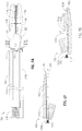
- an alternate embodiment of an instrument 150 includes a reciprocating knife 152 having dispensable tips 152a, 152b, 152c, and 152d.
- An active knife tip 152a defines a distal-most cutting surface of the reciprocating knife 152, and replacement tips 152b, 152c, and 152d are disposed proximally with respect to the active knife tip 152a.
- the reciprocating knife 152 extends between a trigger 154 at a proximal end of the instrument 150 and jaw members 156, 158.
- the trigger 154 is coupled to a pawl 160 that engages the knife 152 about a first or active drive notch or drive surface 164a.
- the trigger 154 may be retracted in the proximal direction of arrow "A” to pivot about a pin 162 and drive the pawl 160 in the distal direction of arrow "B.”
- the pawl 160 bears against active drive notch 164a of the knife 152, and thus, the active knife tip 152a may be induced to traverse a knife channel 166 in the distal direction of arrow "B” to sever tissue captured between the jaw members 156, 158.
- the active knife tip 152a may become contaminated or dull.
- the active knife tip 152a is disposed distally of the replacement knife tips 152b, 152c, and 152d, the presence of the active knife tip 152a prohibits a forward cutting edge of the replacement knife tips 152b, 152c, 152d from contacting tissue and becoming dull.
- the active knife tip 152a may be severed from the knife 152 to reveal a clean and sharp replacement knife tip 152b.
- the knife 152 may be configured such that a score line or an area of relative weakness exists between the tips 152a, 152b, 152c, and 152d and each of the tips 152a, 152b, 152c, and 152d may be chipped off from the remainder of the knife 152 at a precise location.
- each of the knife tips 152a reduces the overall length of the knife 152.
- an adjustment is made at the proximal end of knife 152.
- the pawl 160 may be disengaged from the active drive notch 164a and may be moved to engage a supplementary or replacement drive notch 164b. Additional drive notches 164c, 164d are provided to accommodate knife tips 152c, and 152d.
- an alternate embodiment of an instrument 150a includes an alternate mechanism for compensating for a change in length of a knife 152e.
- the knife 152e includes dispensable knife tips 152f, 152g, 152h and 152i that may be severed from the knife 152e to reveal a clean and sharp replacement knife tip, e.g., tips 152g, 152h and 152i.
- a clean and sharp replacement knife tip e.g., tips 152g, 152h and 152i.
- the removal of the knife tips 152f, 152g, 152h and 152i reduce the overall length of the knife 152e, and thus an adjustment may be necessary to ensure that the replacement knife tips e.g., tips 152g, 152h and 152i, traverse the entire knife channel 166a in subsequent uses.
- the knife 152e is operatively coupled to a trigger 154a by a connecting rod 160a.
- the connecting rod 160a is pivotally coupled to the knife 152e by a pivot pin 160b, and pivotally coupled to the trigger 154a by a connecting pin 160c.
- the trigger 154a is pivotally supported on a stationary support 162a, which provides a stationary reference with respect to the instrument 154a.
- the stationary support 162a also supports a compression spring 162b that maintains the connecting pin 160c of the connecting rod 160a in one of a series of drive slots 164e, 164f, 164g, 164h defined on an upper portion of the trigger 154a.
- the drive slots 164e, 164f, 164g and 164h are each positioned on the trigger 145a to correspond with a respective knife tip 152f, 152g, 152h and 152i such that the respective knife tip 152f, 152g, 152h, 152i may traverse the entire knife channel 166a.
- the trigger 154a may be retracted in the proximal direction of arrow "C” to pivot about the stationary support 162a.
- the upper portion of the trigger 154a swings the direction of arrow "D," which drives the connecting rod 160a and the knife 152e in the distal direction of arrow "E” through the knife channel 166a.
- the upper portion of the trigger 154a reaches a distal-most position.
- the connecting pin 160c is permitted to slip from one drive slot, e.g., slot 164e, to another drive slot, e.g., 164f under the influence of the compression 162b.
- a knife tip e.g., 152f
- the drive slot 164f corresponding to the next available knife tip 152g will drive the connecting rod 160a and knife 152e distally through the knife channel 166a upon subsequent actuation of the trigger 154a.
- the instrument 150a automatically compensates the change in the length of the knife 152e due to the removal of knife tips 152f, 152g, 152h and 152i.
- an alternate embodiment of an instrument 170 includes a protective sheath 172 provided over elongated shaft 174.
- the protective sheath 172 releasably affixed to the elongated shaft 174 to provide protection against contamination during use of the instrument 170.
- the instrument 170 may be prepared for subsequent use by removing the sheath 172, and thereby removing any contamination adhered to the sheath 172.
- a tab 176 protrudes from a longitudinal edge of the sheath 172, and is provided to facilitate removal of the sheath 172 along a seam 178.
- the sheath 172 overlies a supplementary or replacement sheath 180.
- the sheaths 172, 180 may be adhered to one another with a removable adhesive, by electrostatic bonding or other suitable means that permits sheath 172 to be removed as described above.
- the supplementary sheath 180 remains uncontaminated during the initial use, and provides protection to the elongated shaft 174 during subsequent usage. Any number of additional sheaths (not shown) may be provided in a layered configuration for any number of subsequent uses.
- the sheaths 172, 180 may be constructed of a flexible polymeric material, and may permit usage of an actuator such as button 182 therethorugh.
- the button 182 may be operable, for example, to dispense seal plates as described above with reference to FIG. 6A .
- a protective sheath may be provided over other parts of the instrument 170 in addition to the elongated shaft 174.
- a handle assembly (see FIG. 1 ) may be equipped with removable sheaths to provide protection thereto.
- a forceps 200 configured for use in various open surgical procedures may also incorporate many of the features described above.
- Forceps 200 includes a pair of opposing elongated shafts 212a and 212b having an end effector assembly 230 attached to the distal ends 216a and 216b thereof, respectively.
- End effector assembly 230 is similar in design to end effector assembly 14 described above with reference to FIG. 1 .
- End effector assembly 230 and includes pair of opposing jaw members 232 and 234 that are pivotably connected about a pivot pin 265 and which are movable relative to one another to grasp tissue.
- the jaw members 232 and 234 may be configured to receive seal plate assemblies 44, 58 as described above with reference to Figures 2, 3A and 3B .
- the elongated shafts 212a and 212b may be configured to house and dispense seal plates 102, 132 as described above with reference to Figures 6 and 7 , for example.
- Each shaft 212a and 212b includes a handle 215 and 217, respectively, disposed at the proximal end 214a and 214b thereof which each define a finger hole 215a and 217a, respectively, therethrough for receiving a finger of the clinician.
- Finger holes 215a and 217a facilitate movement of the shafts 212a and 212b relative to one another which, in turn, pivot the jaw members 232 and 234 from an open position wherein the jaw members 232 and 234 are disposed in spaced relation relative to one another to a clamping or closed position wherein the jaw members 232 and 234 cooperate to grasp tissue therebetween.
- An electrosurgical cable 268 couples the instrument 200 to a source of electrosurgical energy, and conductive pathways 270 are provided to transmit electrosurgical energy to the jaw members 232, 234.
- a knife trigger 280 is provided to induce a knife (not shown) to transect tissue captured between the jaw members 232, 234.
- a knife similar to knife 152 described above with reference to FIG. 8A may be provided.
Landscapes
- Health & Medical Sciences (AREA)
- Surgery (AREA)
- Engineering & Computer Science (AREA)
- Life Sciences & Earth Sciences (AREA)
- Biomedical Technology (AREA)
- Otolaryngology (AREA)
- Nuclear Medicine, Radiotherapy & Molecular Imaging (AREA)
- Plasma & Fusion (AREA)
- Physics & Mathematics (AREA)
- Heart & Thoracic Surgery (AREA)
- Medical Informatics (AREA)
- Molecular Biology (AREA)
- Animal Behavior & Ethology (AREA)
- General Health & Medical Sciences (AREA)
- Public Health (AREA)
- Veterinary Medicine (AREA)
- Surgical Instruments (AREA)
Claims (11)
- Chirurgisches Instrument (150), umfassend:einen länglichen Schaft, der sich distal von einem Handgriff erstreckt;einen Endeffektor (156, 158), der sich distal von dem länglichen Schaft erstreckt, wobei der Endeffektor (156, 158) eine aktive Kontaktoberfläche (152a) beinhaltet, die darauf angeordnet ist, um bei der Verwendung mit Gewebe in Kontakt zu kommen; undeine Ersatzkontaktoberfläche (152b), die bezüglich der aktiven Kontaktoberfläche (152a) derart angeordnet ist, dass die Gegenwart der aktiven Kontaktoberfläche (152a) die Ersatzkontaktoberfläche (152b) daran hindert, in der Verwendung mit dem Gewebe in Kontakt zu kommen, und wobei die aktive Kontaktoberfläche (152a) vom Endeffektor (156, 158) entfernbar ist, um der Ersatzkontaktoberfläche (152b) in der Verwendung den Kontakt mit dem Gewebe zu erlauben,dadurch gekennzeichnet, dassdie aktive Kontaktoberfläche (152a) eine aktive Messerspitze (152a) an einem distalen Ende eines sich hin- und herbewegenden Messers (152) definiert, wobei die aktive Messerspitze (152a) distal durch den Endeffektor bewegbar ist, um Gewebe zu schneiden.
- Chirurgisches Instrument (150) nach Anspruch 1, wobei die Ersatzkontaktoberfläche eine Ersatzmesserspitze (152b) definiert, und wobei die Ersatzmesserspitze (152b) proximal bezüglich der aktiven Messerspitze (152a) auf dem sich hin- und herbewegenden Messer (152) angeordnet ist.
- Chirurgisches Instrument (150) nach Anspruch 1 oder 2, ferner umfassend einen Aktuator (154), der auf dem Handgriff angeordnet ist, um das hin- und herbewegende Messer (152) vorzuschieben, wobei der Aktuator (154) mechanisch eine aktive Antriebsoberfläche (164e) auf dem sich hin- und herbewegenden Messer (152) in Eingriff nimmt, um die aktive Messerspitze (152a) durch den Endeffektor distal zu bewegen.
- Chirurgisches Instrument (150) nach Anspruch 3, wobei der Aktuator (154) zur Ablösung von der aktiven Antriebsoberfläche (164e) und zum Eingriff mit einer Ersatzantriebsoberfläche (164f) konfiguriert ist, wenn die aktive Messerspitze (152a) entfernt wird, und wobei die Ersatzantriebsoberfläche (164f) proximal der aktiven Antriebsoberfläche (164e) angeordnet ist.
- Chirurgisches Instrument nach Anspruch 1, wobei die aktive Kontaktoberfläche eine Elektrode definiert, die mit einer Quelle elektrochirurgischer Energie gekoppelt ist.
- Chirurgisches Instrument nach einem der vorstehenden Ansprüche, ferner umfassend eine Schutzhülle (172), die entfernbar an dem länglichen Schaft (174) angeheftet ist.
- Chirurgisches Instrument nach Anspruch 6, wobei die Schutzhülle (172) aus einem flexiblen polymeren Material konstruiert ist.
- Chirurgisches Instrument nach einem der vorstehenden Ansprüche, wobei der Endeffektor Backenelemente (156, 158) zum Fangen von Gewebe dazwischen umfasst, und wobei die aktive Messerspitze (152a) bedient werden kann, um einen Messerkanal (166) in einer distalen Richtung zu kreuzen, um Gewebe zu trennen, das zwischen den Backenelementen (156, 158) gefangen ist.
- Chirurgisches Instrument nach einem der vorstehenden Ansprüche, wobei das sich hin- und herbewegende Messer (152) zwischen einem Auslöser (154) an einem proximalen Ende des Instrumentes (150) und Backenelementen (156, 158) erstreckt, wobei der Auslöser (154) mit einer Klinke (160) verbunden ist, die das hin- und herbewegende Messer (152) um eine erste oder aktive Antriebskerbe oder Antriebsoberfläche (164a) in Eingriff nimmt, und wobei der Auslöser (154) in einer proximalen Richtung zurückziehbar ist, um einen Stift (162) zu schwenken und die Klinke (160) in einer distalen Richtung derart anzutreiben, dass die Klinke (160) gegen die erste oder aktive Antriebskerbe oder Antriebsoberfläche (164a) des sich in- und herbewegenden Messers (152) presst, wobei die aktive Messerspitze (152a) in der Lage ist, einen Messerkanal (166) in der distalen Richtung zu kreuzen, um Gewebe zu durchtrennen, das zwischen den Backenelementen (156, 158) gefangen ist.
- Chirurgisches Instrument nach Anspruch 9, wobei die Klinke (160) von der ersten oder aktiven Antriebskerbe oder Antriebsoberfläche (164a) lösbar ist, und bewegbar ist, um eine zusätzliche oder Ersatzantriebskerbe (164b) in Eingriff zu nehmen, um eine Anpassung an einem proximalen Ende des sich hin- und herbewegenden Messers (152) vorzunehmen, um die Ersatzkontaktoberfläche sicher zu stellen, die eine Ersatzmesserspitze (152b) ist, den gesamten Messerkanal (166) kreuzt, wenn die aktive Messerspitze (152a) entfernt wurde, wobei die Gesamtlänge des sich hin- und herbewegenden Messers (152) verringert wird.
- Chirurgisches Instrument nach Anspruch 10, umfassend zusätzliche Antriebskerben (164c, 164d), um Messerspitzen (152c, 152d) zusätzlich zur aktiven Messerspitze und der Ersatzmesserspitze unterzubringen.
Applications Claiming Priority (1)
| Application Number | Priority Date | Filing Date | Title |
|---|---|---|---|
| US13/028,810 US10045811B2 (en) | 2011-02-16 | 2011-02-16 | Surgical instrument with dispensable components |
Publications (3)
| Publication Number | Publication Date |
|---|---|
| EP2489320A2 EP2489320A2 (de) | 2012-08-22 |
| EP2489320A3 EP2489320A3 (de) | 2012-12-12 |
| EP2489320B1 true EP2489320B1 (de) | 2017-06-28 |
Family
ID=45655940
Family Applications (1)
| Application Number | Title | Priority Date | Filing Date |
|---|---|---|---|
| EP12155756.5A Not-in-force EP2489320B1 (de) | 2011-02-16 | 2012-02-16 | Chirurgisches Instrument mit abnehmbaren Komponenten |
Country Status (4)
| Country | Link |
|---|---|
| US (2) | US10045811B2 (de) |
| EP (1) | EP2489320B1 (de) |
| CN (3) | CN107550561B (de) |
| BR (1) | BR102012003461A2 (de) |
Families Citing this family (60)
| Publication number | Priority date | Publication date | Assignee | Title |
|---|---|---|---|---|
| US7364577B2 (en) | 2002-02-11 | 2008-04-29 | Sherwood Services Ag | Vessel sealing system |
| ES2332143T3 (es) | 2001-04-06 | 2010-01-27 | Covidien Ag | Obturador y divisor de vasos con miembros de tope no conductivos. |
| US7367976B2 (en) | 2003-11-17 | 2008-05-06 | Sherwood Services Ag | Bipolar forceps having monopolar extension |
| US7628791B2 (en) | 2005-08-19 | 2009-12-08 | Covidien Ag | Single action tissue sealer |
| US8142473B2 (en) | 2008-10-03 | 2012-03-27 | Tyco Healthcare Group Lp | Method of transferring rotational motion in an articulating surgical instrument |
| US8114122B2 (en) | 2009-01-13 | 2012-02-14 | Tyco Healthcare Group Lp | Apparatus, system, and method for performing an electrosurgical procedure |
| US20100228250A1 (en) * | 2009-03-05 | 2010-09-09 | Intuitive Surgical Operations, Inc. | Cut and seal instrument |
| US8858547B2 (en) | 2009-03-05 | 2014-10-14 | Intuitive Surgical Operations, Inc. | Cut and seal instrument |
| US8187273B2 (en) | 2009-05-07 | 2012-05-29 | Tyco Healthcare Group Lp | Apparatus, system, and method for performing an electrosurgical procedure |
| US8246618B2 (en) | 2009-07-08 | 2012-08-21 | Tyco Healthcare Group Lp | Electrosurgical jaws with offset knife |
| US8430876B2 (en) | 2009-08-27 | 2013-04-30 | Tyco Healthcare Group Lp | Vessel sealer and divider with knife lockout |
| US8112871B2 (en) | 2009-09-28 | 2012-02-14 | Tyco Healthcare Group Lp | Method for manufacturing electrosurgical seal plates |
| US9113940B2 (en) | 2011-01-14 | 2015-08-25 | Covidien Lp | Trigger lockout and kickback mechanism for surgical instruments |
| US8945175B2 (en) | 2011-01-14 | 2015-02-03 | Covidien Lp | Latch mechanism for surgical instruments |
| US10045811B2 (en) | 2011-02-16 | 2018-08-14 | Covidien Lp | Surgical instrument with dispensable components |
| US8864795B2 (en) | 2011-10-03 | 2014-10-21 | Covidien Lp | Surgical forceps |
| US8968308B2 (en) * | 2011-10-20 | 2015-03-03 | Covidien Lp | Multi-circuit seal plates |
| US8968310B2 (en) | 2011-11-30 | 2015-03-03 | Covidien Lp | Electrosurgical instrument with a knife blade lockout mechanism |
| USD680220S1 (en) | 2012-01-12 | 2013-04-16 | Coviden IP | Slider handle for laparoscopic device |
| US8968360B2 (en) | 2012-01-25 | 2015-03-03 | Covidien Lp | Surgical instrument with resilient driving member and related methods of use |
| US8961514B2 (en) * | 2012-03-06 | 2015-02-24 | Covidien Lp | Articulating surgical apparatus |
| US9375282B2 (en) | 2012-03-26 | 2016-06-28 | Covidien Lp | Light energy sealing, cutting and sensing surgical device |
| US9265569B2 (en) | 2012-03-29 | 2016-02-23 | Covidien Lp | Method of manufacturing an electrosurgical forceps |
| US9072524B2 (en) | 2012-06-29 | 2015-07-07 | Covidien Lp | Surgical forceps |
| US9186214B2 (en) * | 2012-09-27 | 2015-11-17 | City Of Hope | Coaptive surgical sealing tool |
| US10772674B2 (en) | 2012-11-15 | 2020-09-15 | Covidien Lp | Deployment mechanisms for surgical instruments |
| US9375205B2 (en) | 2012-11-15 | 2016-06-28 | Covidien Lp | Deployment mechanisms for surgical instruments |
| US11172935B2 (en) | 2014-08-20 | 2021-11-16 | City Of Hope | Hand-held grasping device |
| US10039592B2 (en) | 2014-09-17 | 2018-08-07 | Covidien Lp | Deployment mechanisms for surgical instruments |
| US10080605B2 (en) | 2014-09-17 | 2018-09-25 | Covidien Lp | Deployment mechanisms for surgical instruments |
| US9987077B2 (en) | 2014-09-17 | 2018-06-05 | Covidien Lp | Surgical instrument having a bipolar end effector assembly and a deployable monopolar assembly |
| US9918785B2 (en) | 2014-09-17 | 2018-03-20 | Covidien Lp | Deployment mechanisms for surgical instruments |
| US9987076B2 (en) | 2014-09-17 | 2018-06-05 | Covidien Lp | Multi-function surgical instruments |
| USD844138S1 (en) | 2015-07-17 | 2019-03-26 | Covidien Lp | Handle assembly of a multi-function surgical instrument |
| USD844139S1 (en) | 2015-07-17 | 2019-03-26 | Covidien Lp | Monopolar assembly of a multi-function surgical instrument |
| GB201600546D0 (en) * | 2016-01-12 | 2016-02-24 | Gyrus Medical Ltd | Electrosurgical device |
| US10537381B2 (en) | 2016-02-26 | 2020-01-21 | Covidien Lp | Surgical instrument having a bipolar end effector assembly and a deployable monopolar assembly |
| US10517665B2 (en) * | 2016-07-14 | 2019-12-31 | Covidien Lp | Devices and methods for tissue sealing and mechanical clipping |
| US10631887B2 (en) | 2016-08-15 | 2020-04-28 | Covidien Lp | Electrosurgical forceps for video assisted thoracoscopic surgery and other surgical procedures |
| US10813695B2 (en) | 2017-01-27 | 2020-10-27 | Covidien Lp | Reflectors for optical-based vessel sealing |
| US10973567B2 (en) | 2017-05-12 | 2021-04-13 | Covidien Lp | Electrosurgical forceps for grasping, treating, and/or dividing tissue |
| US11172980B2 (en) | 2017-05-12 | 2021-11-16 | Covidien Lp | Electrosurgical forceps for grasping, treating, and/or dividing tissue |
| USD843574S1 (en) | 2017-06-08 | 2019-03-19 | Covidien Lp | Knife for open vessel sealer |
| USD854684S1 (en) | 2017-06-08 | 2019-07-23 | Covidien Lp | Open vessel sealer with mechanical cutter |
| USD854149S1 (en) | 2017-06-08 | 2019-07-16 | Covidien Lp | End effector for open vessel sealer |
| US11154348B2 (en) | 2017-08-29 | 2021-10-26 | Covidien Lp | Surgical instruments and methods of assembling surgical instruments |
| US11123132B2 (en) | 2018-04-09 | 2021-09-21 | Covidien Lp | Multi-function surgical instruments and assemblies therefor |
| US10828756B2 (en) | 2018-04-24 | 2020-11-10 | Covidien Lp | Disassembly methods facilitating reprocessing of multi-function surgical instruments |
| US10780544B2 (en) | 2018-04-24 | 2020-09-22 | Covidien Lp | Systems and methods facilitating reprocessing of surgical instruments |
| GB2574633B (en) * | 2018-06-13 | 2022-10-05 | Gyrus Medical Ltd | Bipolar electrosurgical instruments |
| US11471211B2 (en) | 2018-10-12 | 2022-10-18 | Covidien Lp | Electrosurgical forceps |
| US11376062B2 (en) | 2018-10-12 | 2022-07-05 | Covidien Lp | Electrosurgical forceps |
| US11350982B2 (en) | 2018-12-05 | 2022-06-07 | Covidien Lp | Electrosurgical forceps |
| US11523861B2 (en) | 2019-03-22 | 2022-12-13 | Covidien Lp | Methods for manufacturing a jaw assembly for an electrosurgical forceps |
| US12402934B2 (en) | 2019-09-15 | 2025-09-02 | Covidien Lp | Electrosurgical instrument for grasping, treating, and/or dividing tissue incorporating thermal management feature |
| PL3815642T3 (pl) | 2019-10-28 | 2023-09-25 | Erbe Elektromedizin Gmbh | Wkład noża i element uszczelniający |
| US11622804B2 (en) | 2020-03-16 | 2023-04-11 | Covidien Lp | Forceps with linear trigger mechanism |
| EP3895644A1 (de) * | 2020-04-15 | 2021-10-20 | Erbe Elektromedizin GmbH | Chirurgisches instrument |
| US12295641B2 (en) | 2020-07-01 | 2025-05-13 | Covidien Lp | Electrosurgical forceps with swivel action nerve probe |
| US11660109B2 (en) | 2020-09-08 | 2023-05-30 | Covidien Lp | Cutting elements for surgical instruments such as for use in robotic surgical systems |
Family Cites Families (47)
| Publication number | Priority date | Publication date | Assignee | Title |
|---|---|---|---|---|
| US4120302A (en) | 1976-10-08 | 1978-10-17 | American Hospital Supply Corporation | Disposable pads for surgical instruments |
| US4509518A (en) * | 1982-02-17 | 1985-04-09 | United States Surgical Corporation | Apparatus for applying surgical clips |
| US5250072A (en) | 1990-12-10 | 1993-10-05 | Jain Krishna M | Surgical clamp jaw cover |
| US5125927A (en) * | 1991-02-19 | 1992-06-30 | Belanger Neil F | Breakaway electrode for surgical cutting and cauterizing tool |
| US5201900A (en) * | 1992-02-27 | 1993-04-13 | Medical Scientific, Inc. | Bipolar surgical clip |
| CA2120828C (en) * | 1993-04-16 | 1999-11-02 | Paul J. Phillips | Surgical hemostatic clip |
| US5330495A (en) | 1993-05-24 | 1994-07-19 | The United States Of America As Represented By The Secretary Of The Air Force | Disposable grafting knife |
| US5693051A (en) | 1993-07-22 | 1997-12-02 | Ethicon Endo-Surgery, Inc. | Electrosurgical hemostatic device with adaptive electrodes |
| US6050996A (en) | 1997-11-12 | 2000-04-18 | Sherwood Services Ag | Bipolar electrosurgical instrument with replaceable electrodes |
| US6273902B1 (en) | 1999-06-18 | 2001-08-14 | Novare Surgical Systems, Inc. | Surgical clamp having replaceable pad |
| US20030109875A1 (en) * | 1999-10-22 | 2003-06-12 | Tetzlaff Philip M. | Open vessel sealing forceps with disposable electrodes |
| US6926712B2 (en) | 2000-03-24 | 2005-08-09 | Boston Scientific Scimed, Inc. | Clamp having at least one malleable clamp member and surgical method employing the same |
| US6840938B1 (en) * | 2000-12-29 | 2005-01-11 | Intuitive Surgical, Inc. | Bipolar cauterizing instrument |
| US7101371B2 (en) | 2001-04-06 | 2006-09-05 | Dycus Sean T | Vessel sealer and divider |
| US20020165549A1 (en) | 2001-04-30 | 2002-11-07 | Medtronic, Inc. | Surgical instrument and attachment |
| WO2002089686A1 (en) * | 2001-05-10 | 2002-11-14 | Rita Medical Systems, Inc. | Rf tissue ablation apparatus and method |
| US7176030B2 (en) | 2002-06-17 | 2007-02-13 | O.R. Solutions, Inc. | Method and apparatus for ensuring sterility of disposable medical items used with medical equipment |
| US6656175B2 (en) | 2001-12-11 | 2003-12-02 | Medtronic, Inc. | Method and system for treatment of atrial tachyarrhythmias |
| CN2548592Y (zh) * | 2002-04-10 | 2003-05-07 | 史志刚 | 医用不沾双极电凝镊 |
| US20040260281A1 (en) * | 2002-09-19 | 2004-12-23 | Baxter Chester O. | Finger tip electrosurgical medical device |
| US7753909B2 (en) * | 2003-05-01 | 2010-07-13 | Covidien Ag | Electrosurgical instrument which reduces thermal damage to adjacent tissue |
| JP4253540B2 (ja) | 2003-07-24 | 2009-04-15 | オリンパス株式会社 | 医療器械 |
| US7232440B2 (en) * | 2003-11-17 | 2007-06-19 | Sherwood Services Ag | Bipolar forceps having monopolar extension |
| US7442193B2 (en) | 2003-11-20 | 2008-10-28 | Covidien Ag | Electrically conductive/insulative over-shoe for tissue fusion |
| US7326204B2 (en) * | 2004-01-16 | 2008-02-05 | St. Jude Medical, Atrial Fibrillation Division, Inc. | Brush electrode and method for ablation |
| US7862561B2 (en) | 2005-01-08 | 2011-01-04 | Boston Scientific Scimed, Inc. | Clamp based lesion formation apparatus with variable spacing structures |
| US7727231B2 (en) | 2005-01-08 | 2010-06-01 | Boston Scientific Scimed, Inc. | Apparatus and methods for forming lesions in tissue and applying stimulation energy to tissue in which lesions are formed |
| US7892228B2 (en) | 2005-02-25 | 2011-02-22 | Boston Scientific Scimed, Inc. | Dual mode lesion formation apparatus, systems and methods |
| EP1883358B1 (de) | 2005-05-25 | 2009-12-02 | Gyrus Medical, Inc. | Operationsinstrument |
| US20070173872A1 (en) * | 2006-01-23 | 2007-07-26 | Ethicon Endo-Surgery, Inc. | Surgical instrument for cutting and coagulating patient tissue |
| US20070261174A1 (en) * | 2006-04-25 | 2007-11-15 | Barker Richard W | Modular tools |
| US20080071269A1 (en) * | 2006-09-18 | 2008-03-20 | Cytyc Corporation | Curved Endoscopic Medical Device |
| US7877853B2 (en) * | 2007-09-20 | 2011-02-01 | Tyco Healthcare Group Lp | Method of manufacturing end effector assembly for sealing tissue |
| US8221416B2 (en) * | 2007-09-28 | 2012-07-17 | Tyco Healthcare Group Lp | Insulating boot for electrosurgical forceps with thermoplastic clevis |
| CN201088624Y (zh) | 2007-11-09 | 2008-07-23 | 上海沪通电子有限公司 | 可高温消毒灭菌的手术附件 |
| US8221417B2 (en) | 2007-11-13 | 2012-07-17 | Boston Scientific Scimed, Inc. | Disposable electro-surgical cover elements and electro-surgical instrument |
| US20090182331A1 (en) | 2008-01-11 | 2009-07-16 | Live Tissue Connect, Inc. | Bipolar modular forceps cover assembly |
| GB0804688D0 (en) * | 2008-03-13 | 2008-04-16 | Gyrus Group Plc | Surgical instrument |
| US20100198248A1 (en) | 2009-02-02 | 2010-08-05 | Ethicon Endo-Surgery, Inc. | Surgical dissector |
| US8876812B2 (en) | 2009-02-26 | 2014-11-04 | Megadyne Medical Products, Inc. | Self-limiting electrosurgical return electrode with pressure sore reduction and heating capabilities |
| US8858547B2 (en) * | 2009-03-05 | 2014-10-14 | Intuitive Surgical Operations, Inc. | Cut and seal instrument |
| US8388647B2 (en) * | 2009-10-28 | 2013-03-05 | Covidien Lp | Apparatus for tissue sealing |
| US10265118B2 (en) * | 2010-05-04 | 2019-04-23 | Covidien Lp | Pinion blade drive mechanism for a laparoscopic vessel dissector |
| US10390889B2 (en) * | 2010-07-26 | 2019-08-27 | St Jude Medical International Holding S.Á R.L. | Removable navigation system and method for a medical device |
| US10045811B2 (en) | 2011-02-16 | 2018-08-14 | Covidien Lp | Surgical instrument with dispensable components |
| US9028492B2 (en) * | 2011-08-18 | 2015-05-12 | Covidien Lp | Surgical instruments with removable components |
| US8845636B2 (en) * | 2011-09-16 | 2014-09-30 | Covidien Lp | Seal plate with insulation displacement connection |
-
2011
- 2011-02-16 US US13/028,810 patent/US10045811B2/en active Active
-
2012
- 2012-02-15 BR BRBR102012003461-1A patent/BR102012003461A2/pt not_active Application Discontinuation
- 2012-02-16 CN CN201710712357.6A patent/CN107550561B/zh not_active Expired - Fee Related
- 2012-02-16 CN CN201510028228.6A patent/CN104605931B/zh not_active Expired - Fee Related
- 2012-02-16 EP EP12155756.5A patent/EP2489320B1/de not_active Not-in-force
- 2012-02-16 CN CN201210037432.0A patent/CN102641154B/zh not_active Expired - Fee Related
-
2018
- 2018-08-13 US US16/102,668 patent/US10893901B2/en not_active Expired - Fee Related
Also Published As
| Publication number | Publication date |
|---|---|
| CN104605931B (zh) | 2017-09-22 |
| CN107550561B (zh) | 2020-10-30 |
| BR102012003461A2 (pt) | 2015-08-04 |
| CN102641154B (zh) | 2015-07-29 |
| CN102641154A (zh) | 2012-08-22 |
| US10045811B2 (en) | 2018-08-14 |
| CN104605931A (zh) | 2015-05-13 |
| EP2489320A2 (de) | 2012-08-22 |
| US10893901B2 (en) | 2021-01-19 |
| US20120209263A1 (en) | 2012-08-16 |
| US20180344388A1 (en) | 2018-12-06 |
| EP2489320A3 (de) | 2012-12-12 |
| CN107550561A (zh) | 2018-01-09 |
Similar Documents
| Publication | Publication Date | Title |
|---|---|---|
| EP2489320B1 (de) | Chirurgisches Instrument mit abnehmbaren Komponenten | |
| EP1532932B1 (de) | Blutgefässversiegelnde Vorrichtung mit Schneidemechanismus | |
| JP5116219B2 (ja) | 切断機構および遠位ロックアウトを備える開胸脈管密封器具 | |
| JP5542274B2 (ja) | 電気外科用組織シーラーおよびカッター | |
| JP5270905B2 (ja) | インライン型の血管密閉分割装置 | |
| EP1645238B1 (de) | Mechanismus zur Gewebetrennung in einem hemostatbauähnlichen Instrument | |
| EP1645240A2 (de) | Instrument zur offenen Versiegelung von Blutgefässen mit einem Schneidemechanismus in Sanduhrform und einer Ratschensicherung |
Legal Events
| Date | Code | Title | Description |
|---|---|---|---|
| PUAI | Public reference made under article 153(3) epc to a published international application that has entered the european phase |
Free format text: ORIGINAL CODE: 0009012 |
|
| AK | Designated contracting states |
Kind code of ref document: A2 Designated state(s): AL AT BE BG CH CY CZ DE DK EE ES FI FR GB GR HR HU IE IS IT LI LT LU LV MC MK MT NL NO PL PT RO RS SE SI SK SM TR |
|
| AX | Request for extension of the european patent |
Extension state: BA ME |
|
| PUAL | Search report despatched |
Free format text: ORIGINAL CODE: 0009013 |
|
| AK | Designated contracting states |
Kind code of ref document: A3 Designated state(s): AL AT BE BG CH CY CZ DE DK EE ES FI FR GB GR HR HU IE IS IT LI LT LU LV MC MK MT NL NO PL PT RO RS SE SI SK SM TR |
|
| AX | Request for extension of the european patent |
Extension state: BA ME |
|
| RIC1 | Information provided on ipc code assigned before grant |
Ipc: A61B 18/14 20060101AFI20121105BHEP |
|
| RAP1 | Party data changed (applicant data changed or rights of an application transferred) |
Owner name: COVIDIEN LP |
|
| 17P | Request for examination filed |
Effective date: 20130603 |
|
| RBV | Designated contracting states (corrected) |
Designated state(s): AL AT BE BG CH CY CZ DE DK EE ES FI FR GB GR HR HU IE IS IT LI LT LU LV MC MK MT NL NO PL PT RO RS SE SI SK SM TR |
|
| 17Q | First examination report despatched |
Effective date: 20150918 |
|
| GRAP | Despatch of communication of intention to grant a patent |
Free format text: ORIGINAL CODE: EPIDOSNIGR1 |
|
| INTG | Intention to grant announced |
Effective date: 20170126 |
|
| GRAS | Grant fee paid |
Free format text: ORIGINAL CODE: EPIDOSNIGR3 |
|
| GRAA | (expected) grant |
Free format text: ORIGINAL CODE: 0009210 |
|
| AK | Designated contracting states |
Kind code of ref document: B1 Designated state(s): AL AT BE BG CH CY CZ DE DK EE ES FI FR GB GR HR HU IE IS IT LI LT LU LV MC MK MT NL NO PL PT RO RS SE SI SK SM TR |
|
| REG | Reference to a national code |
Ref country code: GB Ref legal event code: FG4D |
|
| REG | Reference to a national code |
Ref country code: CH Ref legal event code: EP |
|
| REG | Reference to a national code |
Ref country code: AT Ref legal event code: REF Ref document number: 904162 Country of ref document: AT Kind code of ref document: T Effective date: 20170715 |
|
| REG | Reference to a national code |
Ref country code: IE Ref legal event code: FG4D |
|
| REG | Reference to a national code |
Ref country code: DE Ref legal event code: R096 Ref document number: 602012033882 Country of ref document: DE |
|
| PG25 | Lapsed in a contracting state [announced via postgrant information from national office to epo] |
Ref country code: FI Free format text: LAPSE BECAUSE OF FAILURE TO SUBMIT A TRANSLATION OF THE DESCRIPTION OR TO PAY THE FEE WITHIN THE PRESCRIBED TIME-LIMIT Effective date: 20170628 Ref country code: GR Free format text: LAPSE BECAUSE OF FAILURE TO SUBMIT A TRANSLATION OF THE DESCRIPTION OR TO PAY THE FEE WITHIN THE PRESCRIBED TIME-LIMIT Effective date: 20170929 Ref country code: NO Free format text: LAPSE BECAUSE OF FAILURE TO SUBMIT A TRANSLATION OF THE DESCRIPTION OR TO PAY THE FEE WITHIN THE PRESCRIBED TIME-LIMIT Effective date: 20170928 Ref country code: HR Free format text: LAPSE BECAUSE OF FAILURE TO SUBMIT A TRANSLATION OF THE DESCRIPTION OR TO PAY THE FEE WITHIN THE PRESCRIBED TIME-LIMIT Effective date: 20170628 Ref country code: LT Free format text: LAPSE BECAUSE OF FAILURE TO SUBMIT A TRANSLATION OF THE DESCRIPTION OR TO PAY THE FEE WITHIN THE PRESCRIBED TIME-LIMIT Effective date: 20170628 |
|
| REG | Reference to a national code |
Ref country code: NL Ref legal event code: MP Effective date: 20170628 |
|
| REG | Reference to a national code |
Ref country code: LT Ref legal event code: MG4D |
|
| REG | Reference to a national code |
Ref country code: AT Ref legal event code: MK05 Ref document number: 904162 Country of ref document: AT Kind code of ref document: T Effective date: 20170628 |
|
| PG25 | Lapsed in a contracting state [announced via postgrant information from national office to epo] |
Ref country code: SE Free format text: LAPSE BECAUSE OF FAILURE TO SUBMIT A TRANSLATION OF THE DESCRIPTION OR TO PAY THE FEE WITHIN THE PRESCRIBED TIME-LIMIT Effective date: 20170628 Ref country code: RS Free format text: LAPSE BECAUSE OF FAILURE TO SUBMIT A TRANSLATION OF THE DESCRIPTION OR TO PAY THE FEE WITHIN THE PRESCRIBED TIME-LIMIT Effective date: 20170628 Ref country code: BG Free format text: LAPSE BECAUSE OF FAILURE TO SUBMIT A TRANSLATION OF THE DESCRIPTION OR TO PAY THE FEE WITHIN THE PRESCRIBED TIME-LIMIT Effective date: 20170928 Ref country code: NL Free format text: LAPSE BECAUSE OF FAILURE TO SUBMIT A TRANSLATION OF THE DESCRIPTION OR TO PAY THE FEE WITHIN THE PRESCRIBED TIME-LIMIT Effective date: 20170628 Ref country code: LV Free format text: LAPSE BECAUSE OF FAILURE TO SUBMIT A TRANSLATION OF THE DESCRIPTION OR TO PAY THE FEE WITHIN THE PRESCRIBED TIME-LIMIT Effective date: 20170628 |
|
| REG | Reference to a national code |
Ref country code: FR Ref legal event code: PLFP Year of fee payment: 7 |
|
| PG25 | Lapsed in a contracting state [announced via postgrant information from national office to epo] |
Ref country code: RO Free format text: LAPSE BECAUSE OF FAILURE TO SUBMIT A TRANSLATION OF THE DESCRIPTION OR TO PAY THE FEE WITHIN THE PRESCRIBED TIME-LIMIT Effective date: 20170628 Ref country code: SK Free format text: LAPSE BECAUSE OF FAILURE TO SUBMIT A TRANSLATION OF THE DESCRIPTION OR TO PAY THE FEE WITHIN THE PRESCRIBED TIME-LIMIT Effective date: 20170628 Ref country code: EE Free format text: LAPSE BECAUSE OF FAILURE TO SUBMIT A TRANSLATION OF THE DESCRIPTION OR TO PAY THE FEE WITHIN THE PRESCRIBED TIME-LIMIT Effective date: 20170628 Ref country code: AT Free format text: LAPSE BECAUSE OF FAILURE TO SUBMIT A TRANSLATION OF THE DESCRIPTION OR TO PAY THE FEE WITHIN THE PRESCRIBED TIME-LIMIT Effective date: 20170628 Ref country code: CZ Free format text: LAPSE BECAUSE OF FAILURE TO SUBMIT A TRANSLATION OF THE DESCRIPTION OR TO PAY THE FEE WITHIN THE PRESCRIBED TIME-LIMIT Effective date: 20170628 |
|
| PG25 | Lapsed in a contracting state [announced via postgrant information from national office to epo] |
Ref country code: ES Free format text: LAPSE BECAUSE OF FAILURE TO SUBMIT A TRANSLATION OF THE DESCRIPTION OR TO PAY THE FEE WITHIN THE PRESCRIBED TIME-LIMIT Effective date: 20170628 Ref country code: IT Free format text: LAPSE BECAUSE OF FAILURE TO SUBMIT A TRANSLATION OF THE DESCRIPTION OR TO PAY THE FEE WITHIN THE PRESCRIBED TIME-LIMIT Effective date: 20170628 Ref country code: IS Free format text: LAPSE BECAUSE OF FAILURE TO SUBMIT A TRANSLATION OF THE DESCRIPTION OR TO PAY THE FEE WITHIN THE PRESCRIBED TIME-LIMIT Effective date: 20171028 Ref country code: SM Free format text: LAPSE BECAUSE OF FAILURE TO SUBMIT A TRANSLATION OF THE DESCRIPTION OR TO PAY THE FEE WITHIN THE PRESCRIBED TIME-LIMIT Effective date: 20170628 Ref country code: PL Free format text: LAPSE BECAUSE OF FAILURE TO SUBMIT A TRANSLATION OF THE DESCRIPTION OR TO PAY THE FEE WITHIN THE PRESCRIBED TIME-LIMIT Effective date: 20170628 |
|
| REG | Reference to a national code |
Ref country code: DE Ref legal event code: R097 Ref document number: 602012033882 Country of ref document: DE |
|
| PG25 | Lapsed in a contracting state [announced via postgrant information from national office to epo] |
Ref country code: DK Free format text: LAPSE BECAUSE OF FAILURE TO SUBMIT A TRANSLATION OF THE DESCRIPTION OR TO PAY THE FEE WITHIN THE PRESCRIBED TIME-LIMIT Effective date: 20170628 |
|
| PLBE | No opposition filed within time limit |
Free format text: ORIGINAL CODE: 0009261 |
|
| STAA | Information on the status of an ep patent application or granted ep patent |
Free format text: STATUS: NO OPPOSITION FILED WITHIN TIME LIMIT |
|
| 26N | No opposition filed |
Effective date: 20180329 |
|
| PG25 | Lapsed in a contracting state [announced via postgrant information from national office to epo] |
Ref country code: SI Free format text: LAPSE BECAUSE OF FAILURE TO SUBMIT A TRANSLATION OF THE DESCRIPTION OR TO PAY THE FEE WITHIN THE PRESCRIBED TIME-LIMIT Effective date: 20170628 |
|
| REG | Reference to a national code |
Ref country code: CH Ref legal event code: PL |
|
| PG25 | Lapsed in a contracting state [announced via postgrant information from national office to epo] |
Ref country code: MC Free format text: LAPSE BECAUSE OF FAILURE TO SUBMIT A TRANSLATION OF THE DESCRIPTION OR TO PAY THE FEE WITHIN THE PRESCRIBED TIME-LIMIT Effective date: 20170628 |
|
| REG | Reference to a national code |
Ref country code: BE Ref legal event code: MM Effective date: 20180228 |
|
| PG25 | Lapsed in a contracting state [announced via postgrant information from national office to epo] |
Ref country code: CH Free format text: LAPSE BECAUSE OF NON-PAYMENT OF DUE FEES Effective date: 20180228 Ref country code: LI Free format text: LAPSE BECAUSE OF NON-PAYMENT OF DUE FEES Effective date: 20180228 Ref country code: LU Free format text: LAPSE BECAUSE OF NON-PAYMENT OF DUE FEES Effective date: 20180216 |
|
| PG25 | Lapsed in a contracting state [announced via postgrant information from national office to epo] |
Ref country code: BE Free format text: LAPSE BECAUSE OF NON-PAYMENT OF DUE FEES Effective date: 20180228 |
|
| PG25 | Lapsed in a contracting state [announced via postgrant information from national office to epo] |
Ref country code: MT Free format text: LAPSE BECAUSE OF NON-PAYMENT OF DUE FEES Effective date: 20180216 |
|
| PG25 | Lapsed in a contracting state [announced via postgrant information from national office to epo] |
Ref country code: TR Free format text: LAPSE BECAUSE OF FAILURE TO SUBMIT A TRANSLATION OF THE DESCRIPTION OR TO PAY THE FEE WITHIN THE PRESCRIBED TIME-LIMIT Effective date: 20170628 |
|
| PG25 | Lapsed in a contracting state [announced via postgrant information from national office to epo] |
Ref country code: PT Free format text: LAPSE BECAUSE OF FAILURE TO SUBMIT A TRANSLATION OF THE DESCRIPTION OR TO PAY THE FEE WITHIN THE PRESCRIBED TIME-LIMIT Effective date: 20170628 Ref country code: HU Free format text: LAPSE BECAUSE OF FAILURE TO SUBMIT A TRANSLATION OF THE DESCRIPTION OR TO PAY THE FEE WITHIN THE PRESCRIBED TIME-LIMIT; INVALID AB INITIO Effective date: 20120216 |
|
| PG25 | Lapsed in a contracting state [announced via postgrant information from national office to epo] |
Ref country code: CY Free format text: LAPSE BECAUSE OF FAILURE TO SUBMIT A TRANSLATION OF THE DESCRIPTION OR TO PAY THE FEE WITHIN THE PRESCRIBED TIME-LIMIT Effective date: 20170628 Ref country code: MK Free format text: LAPSE BECAUSE OF NON-PAYMENT OF DUE FEES Effective date: 20170628 |
|
| PG25 | Lapsed in a contracting state [announced via postgrant information from national office to epo] |
Ref country code: AL Free format text: LAPSE BECAUSE OF FAILURE TO SUBMIT A TRANSLATION OF THE DESCRIPTION OR TO PAY THE FEE WITHIN THE PRESCRIBED TIME-LIMIT Effective date: 20170628 |
|
| PGFP | Annual fee paid to national office [announced via postgrant information from national office to epo] |
Ref country code: IE Payment date: 20210122 Year of fee payment: 10 Ref country code: FR Payment date: 20210120 Year of fee payment: 10 |
|
| PGFP | Annual fee paid to national office [announced via postgrant information from national office to epo] |
Ref country code: GB Payment date: 20210120 Year of fee payment: 10 Ref country code: DE Payment date: 20210120 Year of fee payment: 10 |
|
| REG | Reference to a national code |
Ref country code: DE Ref legal event code: R119 Ref document number: 602012033882 Country of ref document: DE |
|
| GBPC | Gb: european patent ceased through non-payment of renewal fee |
Effective date: 20220216 |
|
| PG25 | Lapsed in a contracting state [announced via postgrant information from national office to epo] |
Ref country code: FR Free format text: LAPSE BECAUSE OF NON-PAYMENT OF DUE FEES Effective date: 20220228 |
|
| PG25 | Lapsed in a contracting state [announced via postgrant information from national office to epo] |
Ref country code: IE Free format text: LAPSE BECAUSE OF NON-PAYMENT OF DUE FEES Effective date: 20220216 Ref country code: GB Free format text: LAPSE BECAUSE OF NON-PAYMENT OF DUE FEES Effective date: 20220216 Ref country code: DE Free format text: LAPSE BECAUSE OF NON-PAYMENT OF DUE FEES Effective date: 20220901 |