EP2487792A1 - Circuit de commande de gain automatique et procédé pour la commande de gain automatique - Google Patents
Circuit de commande de gain automatique et procédé pour la commande de gain automatique Download PDFInfo
- Publication number
- EP2487792A1 EP2487792A1 EP11154201A EP11154201A EP2487792A1 EP 2487792 A1 EP2487792 A1 EP 2487792A1 EP 11154201 A EP11154201 A EP 11154201A EP 11154201 A EP11154201 A EP 11154201A EP 2487792 A1 EP2487792 A1 EP 2487792A1
- Authority
- EP
- European Patent Office
- Prior art keywords
- signal
- frequency
- transducer
- output signal
- gain
- Prior art date
- Legal status (The legal status is an assumption and is not a legal conclusion. Google has not performed a legal analysis and makes no representation as to the accuracy of the status listed.)
- Withdrawn
Links
Images


Classifications
-
- H—ELECTRICITY
- H03—ELECTRONIC CIRCUITRY
- H03G—CONTROL OF AMPLIFICATION
- H03G9/00—Combinations of two or more types of control, e.g. gain control and tone control
- H03G9/02—Combinations of two or more types of control, e.g. gain control and tone control in untuned amplifiers
- H03G9/025—Combinations of two or more types of control, e.g. gain control and tone control in untuned amplifiers frequency-dependent volume compression or expansion, e.g. multiple-band systems
-
- H—ELECTRICITY
- H03—ELECTRONIC CIRCUITRY
- H03G—CONTROL OF AMPLIFICATION
- H03G7/00—Volume compression or expansion in amplifiers
- H03G7/002—Volume compression or expansion in amplifiers in untuned or low-frequency amplifiers, e.g. audio amplifiers
Definitions
- the invention relates to an amplifier circuit and a method of amplification using automatic gain control.
- a transducer may perform optimally within a certain range of the signal level delivered to the transducer.
- amplifier circuits and amplification methods that receive an input signal, amplify the input signal by a gain factor to obtain an output signal, deliver the output signal to an output terminal, e.g. connected to a transducer, determine a signal level of the output signal and determine the gain factor from at least the signal level.
- Such amplifier circuits and amplification methods are sometimes referred to as feedback gain control circuits and methods.
- amplifier circuits and amplification methods that receive an input signal, determine a signal level of the input signal, determine a gain factor from at least the signal level, amplify the input signal by a gain factor to obtain an output signal and deliver the output signal to an output terminal, e.g. connected to a transducer.
- Such amplifier circuits and amplification methods are sometimes referred to as feedforward gain control circuits and methods.
- the gain factor may relate the output signal level to the input signal level. It is known to determine the gain automatically in so-called automatic gain control (AGC) circuits and methods.
- the gain factor may e.g.
- the output signal may be delivered to the transducer with a signal level that is within the predetermined range, which may e.g. correspond to an optimal operation range of the transducer.
- the gain factor may also be determined in other ways, e.g., such that the signal level of the output signal is limited to remain below a predetermined maximum level defining a threshold ceiling level. In the latter case, the gain factor may e.g.
- the gain factor may e.g. be substantially inversely proportional to the input signal level when the input signal level is above the certain maximum input signal level, whereby the output signal level would exceed the predetermined maximum level of the gain factor would not be reduced below the first, constant factor.
- the output signal is clipped to the predetermined maximum level, which may e.g. correspond to a maximum operation level of the transducer.
- the gain factor may obtain only positive values, only negative values, or values of either sign, and where the gain factor may obtain (absolute) values that remain below zero and one, that remain above one, or that may obtain values ranging from below one to above one.
- the gain factor may obtain (absolute) values that remain below zero and one, that remain above one, or that may obtain values ranging from below one to above one.
- the transducer would have been capable to receive an output signal with a larger output signal level than obtained with the known amplifier circuit and amplification method, i.e. wherein the input signal could have been amplified more strongly.
- embodiments provide a method of amplifying of an input signal to obtain an output signal, comprising
- the method may be referred to as a feedforward method.
- feedforward method may thus comprise receiving the input signal, amplifying the input signal with a gain factor to obtain the output signal, and applying a frequency-dependent filter having a transfer function with a frequency-dependent filter gain to a copy of the input signal to obtain a filtered signal, the frequency-dependent filter gain being arranged to emphasize frequencies within a predetermined frequency range, determining a signal strength of the filtered signal, and determining the gain factor from at least the signal strength.
- the method may be referred to as a feedback method.
- Such feedback method may thus comprise receiving the input signal, amplifying the input signal with a gain factor to obtain the output signal, and applying a frequency-dependent filter having a transfer function with a frequency-dependent filter gain to a copy of the output signal to obtain a filtered signal, the frequency-dependent filter gain being arranged to emphasize frequencies within a predetermined frequency range, determining a signal strength of the filtered signal, and determining the gain factor from at least the signal strength.
- the at least one of a copy of the input signal and a copy of the output signal may be referred to as "the copy signal”.
- the method may thus provide a gain factor which is determined from the filtered signal.
- the filtered signal may be different from the copy signal.
- the frequency-dependent filter may be configured to emphasize certain frequencies in obtaining the filtered signal from the copy signal. If the certain frequencies are present in the copy output signal, these are emphasized in the filtered signal. The determined signal strength may then be larger compared to the signal strength that would be obtained without such frequency-dependent filter (or equivalently, with a filter with a flat frequency response). Additionally or alternatively, the frequency-dependent filter may be configured to reduce certain frequencies in the filtered signal, whereby the determined signal strength is decreased relative to the signal strength that would be obtained without such frequency-dependent filter.
- the gain factor that is determined from the signal strength of the filtered signal may thus differ from the gain factor that would be obtained without such frequency-dependent filter.
- the relationship between the signal strength and the gain factor be such that the gain factor is lower for larger signal strength, and such that the gain factor is larger for smaller signal strength: when the frequency-dependent filter would then be configured to emphasize certain frequencies, the gain may then only be reduced more when such certain frequencies are present than when such certain frequencies are absent.
- the gain will be reduced to suit the worst-case situation, i.e., will always be maximally reduced.
- Embodiments thus allow to provide an output signal with an increased output signal level, especially when certain frequencies are absent from the output signal.
- the certain frequencies may e.g. correspond to frequencies which may result in a distorted output of the transducer, which may also be referred to as frequencies for which the transducer has a non-linear behaviour, or as frequencies which cause the transducer to introduce harmonic distortion.
- Emphasizing such frequencies in obtaining the filtered signal may then reduce the output signal level to prevent distortion only when the frequency content of the output signal so requires.
- the use of the frequency-selective filter may thus account for effects of frequency-selective non-harmonic behaviour in the output of the transducer, i.e., account for a performance characteristic of the transducer such as e.g.
- the performance characteristic of the transducer relates to a total harmonic distortion characteristic of the transducer.
- the performance characteristic of the transducer relates to any other unwanted behaviour, such as -where the transducer comprises a speaker- resonanant frequencies in the speaker's acoustic cabinet, speaker voice coil temperature etc.
- the frequency-dependent filter gain for frequencies within the predetermined frequency range is larger than the frequency-dependent filter gain for frequencies outside the predetermined frequency range.
- the frequency-dependent filter gain for frequencies outside the predetermined frequency range may e.g. be within the range of-3 dB to substantially 0 dB, such as substantially 0 dB, and the frequency-dependent filter gain for at least part of the frequencies within the predetermined frequency range may e.g. be within the range of 0 dB to + 24 dB, preferably within the range of +3 dB to + 12 dB, and preferably with a maximum filter gain in the range of + 6 dB to + 9 dB.
- the signal strength comprises at least one of a signal level and a signal power of the filtered signal.
- the method further comprises delivering the output signal to a transducer having a performance characteristic, the frequency-dependent filter gain being arranged in consideration of the performance characteristic of the transducer.
- the performance characteristic of the transducer corresponds to a performance measure of the transducer as a function of frequency.
- the performance measure of the transducer may e.g. relate to a total harmonic distortion (THD) of the transducer and the performance characteristic of the transducer may e.g. relate to a total harmonic distortion (THD) characteristic of the transducer, i.e. total harmonic distortion of the transducer as a function of frequency.
- total harmonic distortion (THD) may e.g.
- THD total harmonic distortion
- a ratio of a sum of all powers of higher harmonic frequencies of a fundamental frequency in a transducer output signal to a power of the fundamental frequency in the transducer output signal may be used alternatively, e.g. a ratio of a sum of all powers of higher harmonic frequencies of a fundamental frequency in a transducer output signal to a sum of a power of the fundamental frequency and all powers of higher harmonic frequencies in the transducer output signal, or, equivalently, the ratio of a difference of a total power minus the power of the fundamental frequency and a total power when a pure sine signal at the fundamental frequency is delivered to the transducer.
- Total harmonic distortion may alternatively be defined as an amplitude ratio rather than a power ratio.
- the method further comprises applying a delay to the input signal before amplifying the input signal.
- the delay may e.g. be obtained using a so-called look-ahead buffer.
- the frequency-dependent filter gain is arranged to emphasize frequencies with an emphasize bandwidth around at least one emphasize frequency with an emphasize gain of in the range of 0 dB to 24 dB at the emphasize frequency.
- the transfer curve may e.g. comprise a peak with such center frequency and emphasize gain.
- a variant of the first aspect provides a method of amplifying of an input signal to obtain an output signal, the method comprising:
- determining the gain factor in consideration of the presence of at least one frequency within the predetermined frequency range comprises:
- a second aspect provides an amplifier circuit for amplifying an input signal to obtain an output signal, the amplifier circuit comprising:
- the filter comprises a memory unit arranged to store and retrieve filter parameters of the frequency-dependent filter.
- the amplifier circuit further comprises a delay unit arranged to apply a delay to the input signal, and wherein the amplifier is arranged to amplify the input signal after the delay has been applied to the input signal.
- the delay unit may provide a so-called look-ahead buffer, allowing to delay the input signal with a time delay that is substantially equal to a settling time of amplifier and filter.
- the amplifier circuit is arranged to be connected to a transducer having a performance characteristic, and the frequency-dependent filter gain being arranged in consideration of the performance characteristic of the transducer.
- the frequency-dependent filter corresponds to a function of the performance characteristic of the transducer, such as a first constant times the performance characteristic of the transducer, a sum of a first constant times the performance characteristic of the transducer plus a second constant, or another function.
- a function ⁇ n could e.g.
- G( ⁇ ) fn THD ⁇
- G ⁇ ⁇ ⁇ fn THD ⁇
- G ⁇ ⁇ ⁇ fn THD ⁇ + ⁇
- ⁇ and ⁇ are pre-determined frequency-independent constants, or, in other embodiments, ⁇ and ⁇ are predetermined frequency-dependent functions ⁇ ( ⁇ ) and ⁇ ( ⁇ ) .
- the performance characteristic of the transducer may e.g. relate to a total harmonic distortion characteristic of the transducer.
- the amplifier circuit is arranged to perform a method according to any one of the embodiments described above.
- a variant of the second aspect provides an amplifier circuit for amplifying an input signal to obtain an output signal, the amplifier circuit comprising:
- the gain determiner comprises:
- a third aspect provides a device comprising an amplifier circuit according to any one of the embodiments described above and a transducer, the amplifier circuit being connected to the transducer and arranged to deliver the output signal to the transducer.
- the transducer comprises at least one of a speaker arranged to output sound depending on the output signal, an echo-cancelling circuit arranged to provide echo cancellation using the output signal, a telephone hybrid circuit arranged to receive the output signal as an analogue signal to transform the output signal into a digital signal.
- a fourth aspect provides a method of defining a frequency-dependent filter for use in a method according to any one of the embodiments described above or for use in an amplifier circuit according to any one of the embodiments described above, the method comprising:
- the performance characteristic may e.g. correspond to the THD characteristic, allowing to define the frequency-dependent filter such that frequencies at which the transducer introduces harmonic distortion are emphasized in the filtered signal if such frequencies are present, whereby the signal strength may be increased, and consequently the gain may be reduced.
- the method of defining a frequency-dependent filter for use in a method according to any one of the embodiments described above or for use in an amplifier circuit according to any one of the embodiments described above comprises:
- the extremes may e.g. correspond to frequencies where the THD characteristic shows a peak, e.g. where the total harmonic distortion reflects a resonance.
- the reference level may e.g. correspond to an average level of the performance characteristic, or to a lower floor (or base level) of the performance characteristic.
- a fifth aspect provides a computer program on a computer-readable medium to be loaded by a system comprising a processing unit and a memory, the processing unit being connected to the memory, and the computer program product after being loaded allowing the processing unit to carry out the method according to any one of the embodiments of the first aspect or the fourth aspect.
- a sixth aspect provides a computer-readable medium being provided with a computer program in accordance with the fifth aspect.
- FIG. 1 schematically shows an amplifier circuit 10 of the feedback type according to the prior art.
- the amplifier circuit 10 has an amplifier 2 arranged to receive an input signal 1 from an input terminal 11.
- the input signal 1 is an analogue signal, but in alternative prior art examples, the input signal could be a digital signal.
- the amplifier 2 amplifies the input signal 1 with a gain factor, which may be referred to as g, to obtain an output signal 3.
- the gain factor may also be referred to simply as gain.
- the gain factor is in this example a frequency-independent value, i.e. all frequency components of the input signal 1 are multiplied with the same gain factor.
- the output signal 3 is via an output terminal 12 to a transducer 4, in the example illustrated as a speaker 4.
- the transducer 4 transforms the output signal 3 into a transducer output signal 5.
- the amplifier circuit 10 further has a level detector 7, which receives a feedback signal 6, which is obtained as a copy of the output signal 3.
- the level detector 7 determines a signal strength from detecting a level of the feedback signal 6, e.g. from determining a root-mean-square average over a predetermined period of time of the feedback signal 6.
- the level detector 7 feeds the signal strength as a strength signal 8 to the amplifier 2.
- the amplifier 2 further determines the gain g signal strength using a gain controller provided as part of the amplifier 2.
- the gain controller of the amplifier 2 may e.g. determine the gain g such that the relationship between level Aout of the output signal 3 and level Ain of input signal 1 is as shown in Figure 3 or Figure 4 (see below).
- the amplifier circuit 10 is known as an example of an Automatic Gain Control circuit, abbreviated as AGC.
- Figure 2 schematically shows an exemplary amplifier circuit 10 according to the prior art.
- Figure 2 shows the same elements as Figure 1 , but in the example of Figure 2 , the amplifier 2 used in the amplifier circuit 10 of Figure 1 is shown to have a gain controller 2a and a multiplier 2b.
- the gain controller 2a may determine the gain g, using the signal strength such that the relationship between level Aout of the output signal 3 and level Ain of input signal 1 is as shown in Figure 3 or Figure 4 (see below). In determining the gain g, the gain controller 2a may use an earlier determined gain g, and update the gain g based on the signal strength.
- the multiplier 2 is arranged to multiply the input signal 1 with the gain g to obtain the output signal 3. While determining the gain g, the gain controller may further determine threshold values, such a maximum level to which the output signal 3 is to be limited.
- FIG 3 schematically shows an amplifier characteristic 20 of an amplifier circuit 10 according to the prior art.
- the amplifier characteristic 20 shown in Figure 3 is for example used where the transducer 4 comprises a transmitter.
- the transmitter is designed to operate optimally around a reference level Aref of the output signal 3 received by the transmitter.
- the amplifier characteristic 20 shows level of the input signal 1 as level Ain along the horizontal axis, and level of the output signal 3 as level Aout along the vertical axis.
- the amplifier characteristic 20 relates to the situation wherein the amplifier circuit 10 has had sufficient time to settle after a change in input signal level.
- the amplifier characteristic 20 shows a relationship between level Aout of the output signal 3 and level Ain of input signal 1, wherein the level Aout of the output signal 3 is kept between an upper limit A+ and a lower limit A- for any level Ain of the input signal 1, when larger than a first threshold 23 that is very close to zero (i.e., substantially as long as an input signal is present).
- the amplifier characteristic 20 thus has a substantially flat part 22 for all substantially non-zero Ain levels, and a steep initial part 23 for levels Ain below the first threshold 23.
- the level Aout of the output signal 3 is thus maintained at the approximately constant level Aref.
- FIG 4 schematically shows another amplifier characteristic 25 of an alternative amplifier circuit 10 according to the prior art.
- the amplifier characteristic 25 shown in Figure 4 is for example used where the transducer 4 is a speaker.
- the speaker is designed to operate optimally from a zero-level of the output signal 3, corresponding to silence, to usually a maximum level Aclip of the output signal 3, corresponding to a sound level of the transducer output signal 5 with a maximum acceptable distortion.
- the amplifier characteristic 25 shows level of input signal 1 as level Ain along the horizontal axis, and level of output signal 3 as level Aout along the vertical axis.
- the amplifier characteristic 20 relates to the situation wherein the amplifier circuit 10 has had sufficient time to settle after a change in input signal level.
- the amplifier characteristic 25 shows a relationship between level Aout of the output signal 3 and level Ain of input signal 1, wherein the level Aout of the output signal 3 is substantially proportional to level Ain up to a level Aclip of the output signal, corresponding to a threshold 26 of level Ain.
- the level Aout of the output signal 3 is thus substantially maximized (which may also be referred to as limited or clipped) to level Aclip.
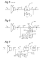
- FIG. 5 schematically shows an feedforward-type exemplary amplifier circuit 10' according to the prior art.
- Figure 5 shows similar elements as the feedback-type exemplary amplifier circuit 10 of Figure 1 , but in the example of Figure 5 , the amplifier further has a level detector 7', which receives a feedforward signal 6', which is obtained as a copy of the input signal 1.
- the level detector 7' may e.g. determine the signal strength of the feedforward signal 6' and feed the signal strength as a strength signal 8 to the amplifier 2.
- the amplifier 2 may, using its gain controller, determine the gain g from the signal strength represented by the strength signal 8.
- the gain may e.g. be determined such that the relationship between level Aout of the output signal 3 and level Ain of input signal 1 is as shown in Figure 3 or Figure 4 (see below).
- the amplifier circuit 10' is also known as an example of a Automatic Gain Control circuit.
- A+ ( Figure 3 ) and Aclip ( Figure 4 ) are usually designed such that the signal level of the output signal 3 is limited to remain below a certain maximum level, such as Aclip in Figure 4 .
- the certain maximum level is usually designed such that the transducer 4 transforms the output signal 3 into the transducer output signal 5 substantially within predetermined performance of the transducer for any possible input signal 1.
- the predetermined performance of the transducer corresponds, e.g., to a transformation with substantially no distortion for any possible input signal 1.
- FIG 6 schematically shows an exemplary amplifier circuit 100 according to an embodiment.
- the amplifier circuit 100 has an amplifier 102 (which may be similar to the amplifier circuit 2 of Figure 1 ) arranged to receive an input signal 101 from an input terminal 111.
- the input signal 101 is an analogue signal, but in alternative prior art examples, the input signal could be a digital signal.
- the amplifier 102 amplifies the input signal 101 1 with a gain factor, which may be referred to as g, to obtain an output signal 103.
- the gain factor is in this example a frequency-independent value, i.e. all frequency components of the input signal 1 are multiplied with the same gain factor.
- the output signal 103 is connected, via an output terminal 112, to a transducer 4, in the example illustrated as a speaker 4.
- the transducer 4 transforms the output signal 3 into a transducer output signal 5.
- the amplifier circuit 100 further has a filter 109 arranged to receive a feedback signal 106, which is obtained as a copy of the output signal 3, and to apply a frequency-dependent filter to obtain a filtered signal 116.
- the a frequency-dependent filter has a transfer function with a frequency-dependent filter gain.
- the frequency-dependent filter gain may be arranged to emphasize frequencies within a predetermined frequency range.
- the amplifier circuit 100 further has a level detector 107, which receives the filtered signal 116.
- the level detector 107 detects a signal strength of the filtered signal.
- the signal strength is, in this exemplary embodiment, a level of the filtered signal 116, and may be detected e.g. from determining an average of amplitude over a predetermined period of time of the filtered signal 116.
- the signal strength may alternatively relate to a signal power, which may be detected e.g. from determining a root-mean-square average over a predetermined period of time of the filtered signal 116.
- the level detector 107 determines the signal strength of the filtered signal 116 and feed the signal strength as a strength signal 108 to the amplifier 2.
- the amplifier 102 determines, using its gain controller 102a, determines the gain g from the level of the filtered signal 116 and uses the gain g as thus determined to amplify the input signal 101 to obtain the output signal 103, e.g. using a multiplier 102b.
- gain controller 102a may e.g. determine the gain g such that the relationship between level Aout of the output signal 3 and level Ain of input signal 1 is as shown in Figure 3 or Figure 4 (see above).
- the filter 109 and the level detector 107 thus cooperate as a gain determiner 113 to determine the gain g.
- the amplifier circuit 100 thus differs from the known amplifier circuit 10 at least in that the amplifier circuit 100 further has a filter 109 which is arranged to apply a frequency-dependent filter to the copy of the output signal 106 obtain a filtered signal 116, and in that the level detector 107 uses the filtered signal 116 rather than the copy of the output signal 106.
- the frequency-dependent filter applied by filter 109 may be designed according to a predetermined specification.
- the frequency-dependent filter may e.g. correspond to emphasizing (i.e., enhancing) specific frequencies to obtain a filtered signal with an increased level and a corresponding reduction of the gain, compared to the prior art, whereby the output signal is e.g. only reduced when such specific frequencies are present.
- the frequency-dependent filter may thus e.g. emphasize specific frequencies corresponding to frequencies where the transducer shows unwanted behaviour, such as where the transducer shows distortion and/or where the transducer shows a resonance such as resonanant frequencies in the speaker's acoustic cabinet and/or where the transducer shows unwanted behaviour of non-acoustic nature such as in unwanted effects in speaker voice coil temperature.
- the frequency-dependent filter may, in embodiments, reflect the performance characteristic of the transducer 4, i.e.
- the performance characteristic may e.g. correspond to the THD characteristic, which may be represented as THD(j ⁇ ), wherein ⁇ denotes the frequency and wherein THD(j ⁇ ) is a real number.
- the frequency-dependent filter may be determined in consideration of the THD characteristic.
- the frequency-dependent gain of the frequency-dependent filter may be referred to as "emphasize gain function" or "filter gain”, and will be denoted with
- the frequency-dependent filter gain may alternatively be referred to with G( ⁇ ) .
- THD(j ⁇ ) is defined as a power ratio of the sum of the higher-harmonic frequencies and the fundamental frequency, and designed to be 0 in the absence of any total harmonic distortion.
- the frequency-dependent filter may be implemented as a analogue filter or a digital filter.
- a digital frequency-dependent filter is preferably an infinite impulse response (IIR) filter, but may in alternative embodiments be a finite impulse response filter (FIR) or another suitable filter.
- IIR infinite impulse response
- FIR finite impulse response filter
- An example of the frequency-dependent filter is given in Figure 10b and will be discussed below.
- An example of the resulting amplifier characteristic 125 of amplifier circuit 100 is shown in Figure 11 .
- Figure 10a schematically shows a performance characteristic 121 of an exemplary transducer.
- the horizontal axis corresponds to the frequency of a signal provided to the transducer, on a logarithmic scale.
- the vertical axis shows a measure of performance R, of the transducer output signal, on a logarithmic scale, wherein the performance decreases in the vertical direction along the vertical axis.
- the measure of performance shown in Figure 10a corresponds e.g. to a measure of total harmonic distortion of the speaker when the transducer comprises a speaker, to a measure of echo distortion in a telephone hybrid circuit, or to a measure of attenuation of an echo cancelling circuit when the transducer comprises an echo cancelling circuit.
- the performance characteristic 121 shows the measure of performance R (such as total harmonic distortion in this example) as a function of the frequency of the signal provided to the transducer. It may be observed that the performance characteristic 121 shows two peaks at frequencies indicated with f1 and f2. It is shown that the performance characteristic 121 reaches a maximum value Rmax at frequency f2.
- Figure 10a also indicated an average level Ravg corresponding to the average value of the performance characteristic 121.
- the average level Ravg may e.g. correspond to the average value THDavg described above, where the performance characteristic 121 relates to total harmonic distortion.
- the performance characteristic 121 of the corresponding transducer may relate to other measures of performance.
- the performance characteristic may correspond to a relative amplitude of the transducer output signal which may show resonance frequencies.
- Figure 10b schematically shows an exemplary transfer function, also referred to as frequency-dependent filter curve 122, of a filter 109 designed to be used with a transducer having the performance characteristic 121 shown in Figure 10a .
- the horizontal axis corresponds to the frequency of a signal provided to the filter, shown on a logarithmic scale.
- the vertical axis show the relative filter amplification of the filter output signal, on a logarithmic scale.
- the exemplary frequency-dependent filter curve 122 shows the relative amplification as a function of the frequency of the signal provided to the filter and has two peaks at the frequencies corresponding to f1 and f2 of the performance characteristic 121 of the exemplary transducer of Figure 10a .
- the exemplary frequency-dependent filter curve 122 thus emphasizes frequencies within a first predetermined frequency range R1 around center frequency f1 and within a second predetermined frequency range R2 around center frequency f2.
- the emphasize gain at frequencies f1 and f1 are in this example in the range of 6 - 9 dB, but could in alternative embodiments have other values, typically within the range of 0 dB - 24 dB.
- the first predetermined frequency range R1 and the second predetermined frequency range R2 may together be referred to as the predetermined frequency range.
- the frequency-dependent filter curve 122 or transfer function thus comprises a frequency-dependent filter gain arranged to emphasize frequencies within the predetermined frequency range.
- the center frequencies f1 and f2 are approximately 800 Hz and 1300 Hz respectively with corresponding emphasis bandwidths (defined as full width half maximum) of approximately 75-100 HZ, and the predetermined frequency ranges R1 and R2 are each approximately 200 Hz.
- the frequency-dependent filter gain may be arranged to emphasize frequencies within an emphasize bandwidth around a center frequency in the range of 100 Hz - 2 kHz, with the emphasize bandwidth being in the range of 5 - 20% of the center frequency.
- the predetermined frequency range is a range within a frequency range of 40 Hz - 40 kHz, preferably within a frequency range of 100 Hz - 4 kHz.
- Figure 11 schematically shows an exemplary amplifier characteristic 125 of an amplifier circuit 100 according to an embodiment.
- the amplifier characteristic 125 shown in Figure 11 is for example used where the transducer 4 is a speaker, and may be compared to amplifier characteristic 25 of the prior art shown in Figure 4 .
- the amplifier characteristic 125 shows level of the input signal 1 as level Ain along the horizontal axis, and level of the output signal 3 as level Aout along the vertical axis.
- the amplifier characteristic 125 shows a relationship between level Aout of the output signal 103 and level Ain of input signal 101, wherein the level Aout of the output signal 103 is substantially proportional to level Ain up to a level Aclip of the output signal.
- the level Aout of the output signal 103 is hereby substantially limited to remain below level Aclip
- the level Aout may continue to increase beyond Aclip especially when the output signal 103 has a relatively low abundance of frequency components at frequencies f1 and f2 (or, in general, of frequencies where the frequency-dependent filter curve 122 is relatively large) when using an amplifier circuit 100 according to an embodiment.
- Figure 11a schematically shows three curves 125a, 125b, 125c corresponding to three different, increasing degrees of presence of frequencies components f1 and/or f2. It may be observed that the three curves show different improvements of resulting levels Aout of the output signal 103. It may be observed that the lowest degree of presence of the frequency components f1 and f2, i.e.
- the resulting output level Aout is increased most significantly relative to the prior art situation.
- the output signal level may thus be increased compared to the prior art for many input signals 101.
- Figure 7 schematically shows an exemplary amplifier circuit 100 according to an alternative embodiment.
- Figure 7 shows the same elements as Figure 6 , and further shows a volume controller 130 as part of the amplifier circuit 100.
- the volume controller 130 allows a user of a device with the amplifier circuit 100, to adjust the signal level of the input signal 101. The user may thus e.g. increase the volume of the speaker 5 (as long as the output signal is within the range where it is proportional to the input signal - refer to Figure 4 ).
- the volume controller 130 may, in alternative embodiments, be automatically operated by a further unit in the device, e.g., when the transducer is a transmitter, the volume controller may be operated in dependence on the type of signal to be transmitted as is determined by the further unit.
- the volume controller 130 may be in communication with the amplifier 102 using a volume level signal 119 to provide the amplifier 102 with an indication of settings of the volume controller 130 via the volume level signal 119. This may allow the amplifier 102 to determine the gain also in consideration of the settings of the volume controller 130.
- Figure 8 schematically shows an exemplary amplifier circuit 100 according to an alternative embodiment.
- Figure 8 shows the same elements as Figure 7 , but the position of the volume controller is changed compared to Figure 7 .
- the volume controller 131 of Figure 8 allows a user of a device with the amplifier circuit 100, to adjust the signal level of the output signal 103 before the output signal is delivered to the transducer.
- the volume controller 131 is in communication with the amplifier 102, in particular its gain controller 102a, using a volume level signal 119 allowing the gain controller 102a.
- the volume level signal 119 comprises an indication of settings of the volume controller 130 via the volume level signal 119. This may allow the amplifier 102 to determine the gain also in consideration of the settings of the volume controller 131.
- the volume controller 132 may e.g. reduce the gain g in order to reduce the output signal level of the output signal 103 when the volume level signal 119 indicates a volume increase by the volume controller 131, and thereby to limit the level of the signal as delivered to the transducer 4.
- Figure 9 schematically shows a method of amplifying of an input signal to obtain an output signal according to an embodiment.
- the method comprises receiving 201 the input signal, amplifying 202 the input signal with a gain factor to obtain the output signal, and outputting 203 the output signal.
- the method further comprises applying 202 a frequency-dependent filter to a copy of the output signal to obtain a filtered signal.
- the method further comprises applying 202 a frequency-dependent filter to a copy of the input signal obtain the filtered signal.
- the method further comprises determining 207 a signal strength of the filtered signal..
- the method further comprises determining 208 the gain factor from at least the signal strength.
- Figure 12 schematically shows an amplifier circuits according to an alternative embodiment.
- Figure 12 shows similar elements as Figure 6 , indicated with the same reference numbers, and further shows a buffer 110 that is configured to delay the input signal 101 before being received by the amplifier 102 to be amplified with the gain factor to obtain the output signal 103 .
- the buffer 110 is arranged to store the input signal 101 for a certain time after which the input signal is retrieved as a delayed input signal 101D.
- the delayed input signal 101D is then amplified with the gain as determined by the gain determiner 102a in the amplifier 102.
- the buffer 110 may be referred to as "look ahead buffer". The effect of using the look ahead buffer is that the gain is effectively applied using a delayed version of the input signal.
- the delay provided by the look ahead buffer 110 is preferably approximately equal to the settling time of the filter 109 and the level detector 107, or, in general terms, determined in dependence on the relevant time constants of the filter's loop and gain.
- Filter 109 preferably has a minimal group delay, and may be implemented as an infinite impulse response (IIR) filter.
- the amplifier 102 of Figure 12 comprises a gain controller 102a and a first multiplier 102b1.
- the first multiplier 102b1 receives a gain from the gain controller 102a, similar to multiplier 102b in Figure 6 , and multiplies the copy 106 of the input signal with the gain to obtain a gained input signal 106G.
- the gained input signal 106D is received by filter 109 which determines a filtered signal 116 similar to the situation in Figure 6 , wherein the filter 109 receives a gained copy of the output signal, i.e. the copy 106 of the output signal, and determines filtered signal 116.
- the level detector 107 receives the filtered signal 116 and determined a strength signal 108.
- the gain controller 102a receives the strength signal 108 from the level detector 107, and determines the gain factor g from at least the strength signal 108 .
- the amplifier 102 further comprises a second multiplier 102b2 which receives the gain factor g from the gain controller 102a and the delayed input signal 101D from the look ahead buffer 110, and applies the gain factor 9 to the delayed input signal 101D to obtain the output signal 103.
- Figure 13a and Figure 13b schematically show amplifier circuits according to alternative embodiments.
- Figure 13a and Figure 13 represent feedforward versions of the embodiments shown in Figure 5 and Figure 12 respectively.
- Figure 13a shows that, compared to the known amplifier circuit shown in Figure 5 , the amplifier circuit further comprises a filter 109 which is arranged to apply a frequency-dependent filter to a copy 106' of the input signal 101 to obtained a filtered signal 116, and the level detector 107 is arranged to receive the filtered signal 116 and to determine a strength signal 108 indicating a signal strength of the filtered signal 116 from the filtered signal 116.
- Figure 13b shows an amplifier circuit of the feedforward type, which, compared to Figure 13a , further comprises a buffer 110.
- the buffer 110 is arranged to delay the input signal 101, similar to the buffer 110 shown in Figure 12 , and may again be referred to as a "look ahead buffer".
- the amplifier 102 is arranged to receive the delayed input signal 101D and to multiply the delayed input signal 101D with the gain factor g (determined from a signal strength of the filtered signal 116 obtained from applying a frequency-dependent filter to a copy 106' of the input signal) to obtain the output signal 103.
- the gain factor g determined from a signal strength of the filtered signal 116 obtained from applying a frequency-dependent filter to a copy 106' of the input signal
- Figure 14a - Figure 14c schematically show devices according to various embodiments.
- Figure 14a shows a device 1000 with an amplifier circuit 100 according to an embodiment and a transducer 4 connected to the amplifier circuit 100.
- the device 1000 further comprises additional circuitry 1001, e.g., comprising a storage unit, a signal source, a signal transceiver, a display unit, an user input interface, or the like.
- FIG 14b shows an example of a device 1020 that can be used in a Public Switched Telephone Network (PSTN).
- PSTN Public Switched Telephone Network
- the device connects between a 4-wire digital cable 1121 connecting to a digital network a 2-wire analogue telephone line 1123, e.g., a PSTN line connecting to a PSTN phone.
- the device 1020 receives digital telephone signals from a first wire 1121 a of the 4-wire digital cable 1121 using a transceiver 1021, which routes the signal as input signals 101 to amplifier circuit 100.
- PSTN Public Switched Telephone Network
- the amplifier circuit 100 are amplifier circuits 100 according to embodiments, preferably according to the same embodiment, and comprise an amplifier 102 for receiving the input signal 101, a, filter 109 for filtering output signals 103, and a level detector 107, for detecting the signal strength of the filtered signal obtained from the filter 109.
- the amplifier circuit 100 delivers respective the output signals 103 to a transducer 4.
- the transducer 4 comprises a telephone hybrid circuit.
- the output signal 103 are delivered as a digital signal to the telephone hybrid circuit 4.
- the telephone hybrid circuit 4 is arranged to receive the output signal 103 and to transform the output signals into an analogue PSTN signal, which is delivered 2-wire analogue line 1123.
- the telephone hybrid circuit 4 is arranged to receive signals from the 2-wire line 1123 and to deliver the received signal as a digital signal 104 to the transceiver 1021, which drives a second line 1121b of the 4-wire digital cable 1121.
- Figure 14c shows an example of another device 1030 according to another embodiment.
- the device 1030 of Figure 14c is used for echo cancellation in e.g. a telephone that can be operated in a handsfree mode.
- Device 1030 has an amplifier circuit 100 according to an embodiment and a transducer 4 connected to the amplifier circuit 100.
- the telephone comprises a speaker 1004, a receiver 1032 for receiving an incoming signal 1031 representing an audio signal to be emitted by the speaker 1004, a microphone 1005 for receiving audio signals, notably speech of the a user of the telephone, and a transmitter 1034 for transmitting an outgoing signal 1033 representing the audio signal receive by the microphone 1005.
- the incoming signal 1031 and the outgoing signal 1033 which may e.g. be wireless or wired signals.
- the transducer 4 shown in this embodiment comprises the speaker 1004 and the microphone 1005, as well as an echo cancellation filter 1036, an echo cancellation adder 1037 and a non-linear processor 1038.
- the echo cancellation filter 1036, an echo cancellation adder 1037 and a non-linear processor 1038 are arranged to cooperate to perform an acoustic echo cancellation of the audio signal transmitted by the speaker 1004 and (partially) received by the microphone 1005.
- the audio signal generated by the speaker 1004 as far as received by the microphone 1005 is modelled by the echo cancellation filter 1036 and subtracted by the echo cancellation adder 1037 and processed by the non-linear processor 1038 to obtain a signal wherein the contribution of the audio signal generated by the speaker 1004 is largely cancelled and can be delivered by the non-linear processor 1038 to the transmitter 1034 to be transmitted substantially free from an echo component.
- the filter 109 in the amplifier circuit 100 models a performance characteristic of the echo path from the speaker 1004 to the microphone 1005.
- frequencies at which the speaker 1004 gives a distorted signal e.g.
- the filtered signal 109 may be emphasized in the filtered signal 109, whereby the level detector 107 determines the signal strength in dependence on the filtered signal, and the gain controller controls the gain 108 delivered to the multiplier such that the gain may be reduced when signals with frequencies that may cause a distortion of the speaker output 1004 are present.
- Such signals could not only have an effect on the quality of the audio signal as heard by a user, but could also result in a mismatch between the modelling of the echo cancellation filter 1036 and the actual path contribution, as the modelling may e.g. be such that any harmonic distortion of the speaker 1004 is not accounted for.
- transducers involving other types of echo cancellation, e.g., where the transducer comprises a receiver and a transmitter in e.g. a data network.
- the device 1030 may further be adapted to comprise and operate with a volume controller as shown in Figure 7 or Figure 8 .
- Figure 15 shows an exemplary embodiment of filter 109.
- Figure 15a shows a filter unit 109F.
- the filter unit 109F is capable of receiving the feedback signal 106 (or, in alternative embodiments, the feedforward signal 106') and applying a frequency-dependent filter to the feedback signal to obtain the filtered signal 116.
- the filter unit 109F may e.g. comprise an analogue filter with a predetermined frequency response.
- the filter unit 109F may alternatively comprise an analogue filter with an adjustable frequency response, e.g. having adjustable resistors or other adjustable components for adapting the frequency response of the filter to the transducer that is connected to the amplifier circuit during use.
- the filter unit 109F may comprise a filter memory 109S that can be read by the filter unit 109F to obtain a setting for the adjustable resistors or the other adjustable components.
- the filter unit 109F may comprise a digital filter with a plurality of filter taps, wherein values for the filter taps are stored in and retrieved from a filter memory 109S.
- the values for the filter taps may be stored directly, or in a parameterized format, e.g. using parameters indicating central frequencies and widths of a plurality of frequency peaks of a predetermined shape.
- the filter memory 109S could be readable and/or writable using an external configuration device 109E, by which a qualified user can configure the frequency-dependent filter according to the transducer that is connected to the amplifier circuit during manufacturing of a specific device, e.g. according to the performance characteristic of a connected speaker.
- Figure 16 schematically illustrates a method of configuring an amplifier circuit according to an embodiment.
- the transducer 4 comprises a speaker to illustrate the method, but the method may be used mutatis mutandis for other transducers.
- the method comprises configuring S1 the filter and configuring S2 the automatic gain circuit comprising the amplifier and the level detector.
- the output signal of the amplifier will be referred to as a speaker signal.
- the speaker signal thus corresponds, during later use, to the input signal amplified with the gain.
- FIG 16 shows that configuring S1 the filter may comprise obtaining S11 a performance characteristic of the speaker from measuring a performance measure of the speaker as a function of frequency, using a speaker that is representative of a speaker to be connected during use to the amplifier circuit; and defining S22 a frequency-dependent filter as a function of the performance characteristic.
- extremes in the performance characteristic are reflected in corresponding extremes in the frequency-dependent filter.
- the average level (or another suitable reference level such as a base level) of the performance characteristic is reflected in an average level of the frequency-dependent filter gain.
- the performance characteristic may e.g. correspond to a total harmonic distortion of speaker output as a function of frequency. Measuring the performance measure of the speaker as a function of frequency may e.g.
- measuring the performance measure of the speaker as a function of frequency may e.g. be performed at a plurality of speaker signal levels, to obtain a frequency-dependent filter that also depends on the speaker signal level.
- FIG 16 shows that configuring S2 the automatic gain circuit may e.g. comprise measuring S21 speaker output level as a function of speaker signal level to obtain a speaker saturation curve; determining S22 from the speaker saturation curve a speaker saturation signal level corresponding to a maximum speaker signal level where the speaker output level has a saturation below a predetermined threshold; and determining S23 gain values as a function of input level supplied to the amplifier such that the speaker signal level is limited to remain below the maximum speaker signal level when the gain values are applied.
- the amplifier circuit as thus configured, may be used to limit the speaker output level to remain below the predetermined threshold.
- the speaker may be operated in a regime wherein the speaker output level is substantially proportional to the speaker signal level, as the speaker signal level is limited to maintain below the speaker saturation signal level.
- Figure 16 further indicates with dashed box SR that, in embodiments, the method may comprise determining SR whether configuring S1 the filter and configuring S2 the automatic gain circuit is to be repeated. If so, dashed arrow SRA indicated that the method may be executed in another iteration.
- the method may e.g. comprise multiple iterations with different signal levels applied to the speaker or for a plurality of operation conditions, such as a handsfree mode and a handheld mode of a speaker in a handheld phone, corresponding to different speaker output levels.
- FIG 17 an overview is given of a computer arrangement that can be used to carry out a method according to an embodiment.
- the computer arrangement shown in Figure 17 is arranged to perform the exemplary method of Figure 16 .
- a similar computer arrangement may be usable to perform other methods or elements thereof, such as the method of amplification.
- the arrangement shown in Figure 17 comprises a processor 2001 for carrying out arithmetic operations.
- the processor 2001 is connected to a plurality of memory components, including a hard disk 5, Read Only Memory (ROM) 2007, Electrically Erasable Programmable Read Only Memory (EEPROM) 2009, and Random Access Memory (RAM) 2011. Not all of these memory types need necessarily be provided.
- these memory components need not be located physically close to the processor 2001 but may be located remote from the processor 2001.
- the processor 2001 is also connected to means for inputting instructions, data etc. by a user, like a keyboard 2013, and a mouse 2015.
- Other input means such as a touch screen, a track ball and/or a voice converter, known to persons skilled in the art may be provided too.
- a reading unit 2017 connected to the processor 2001 is provided.
- the reading unit 2017 is arranged to read data from and possibly write data on a data carrier like a floppy disk 2019 or a CD 2021.
- Other data carriers may be tapes, DVD, BD, etc. as is known to persons skilled in the art.
- the processor 201 is also connected to a printer 2023 for printing output data on paper, as well as to a display 203, for instance, a cathode-ray tube monitor or a LCD (Liquid Crystal Display) screen, or any other type of display known to persons skilled in the art.
- the processor 2001 may be connected to a communication network 2027, for instance, the Public Switched Telephone Network (PSTN), a Local Area Network (LAN), a Wide Area Network (WAN), etc. by means of I/O means 2025.
- the processor 201 may be arranged to communicate with other communication arrangements through the network 2027.
- the data carrier 2019, 2021 may comprise a computer program product in the form of data and instructions arranged to provide the processor with the capacity to perform a method in accordance with the invention.
- the processor 2001 may be implemented as standalone system, or as a plurality of parallel operating processors each arranged to carry out subtasks of a larger computer program, or as one or more main processors with several sub-processors. Parts of the functionality of the invention may even be carried out by remote processors communicating with processor 2001 through the network 2027.
- the processor 2001 may be included in a device, e.g. as a so-called embedded processor.
- Units described as separate units may be combined into one single unit.
- a unit described as a single unit may be implemented using a plurality of units of different or equal type, which cooperate tom provide the function of the single unit.
Landscapes
- Engineering & Computer Science (AREA)
- Multimedia (AREA)
- Amplifiers (AREA)
Priority Applications (2)
| Application Number | Priority Date | Filing Date | Title |
|---|---|---|---|
| EP11154201A EP2487792A1 (fr) | 2011-02-11 | 2011-02-11 | Circuit de commande de gain automatique et procédé pour la commande de gain automatique |
| US13/331,302 US8965011B2 (en) | 2011-02-11 | 2011-12-20 | Automatic gain control circuit and method for automatic gain control |
Applications Claiming Priority (1)
| Application Number | Priority Date | Filing Date | Title |
|---|---|---|---|
| EP11154201A EP2487792A1 (fr) | 2011-02-11 | 2011-02-11 | Circuit de commande de gain automatique et procédé pour la commande de gain automatique |
Publications (1)
| Publication Number | Publication Date |
|---|---|
| EP2487792A1 true EP2487792A1 (fr) | 2012-08-15 |
Family
ID=44117225
Family Applications (1)
| Application Number | Title | Priority Date | Filing Date |
|---|---|---|---|
| EP11154201A Withdrawn EP2487792A1 (fr) | 2011-02-11 | 2011-02-11 | Circuit de commande de gain automatique et procédé pour la commande de gain automatique |
Country Status (2)
| Country | Link |
|---|---|
| US (1) | US8965011B2 (fr) |
| EP (1) | EP2487792A1 (fr) |
Families Citing this family (7)
| Publication number | Priority date | Publication date | Assignee | Title |
|---|---|---|---|---|
| US20130287203A1 (en) * | 2012-04-27 | 2013-10-31 | Plantronics, Inc. | Reduction of Loudspeaker Distortion for Improved Acoustic Echo Cancellation |
| EP2675063B1 (fr) * | 2012-06-13 | 2016-04-06 | Dialog Semiconductor GmbH | Circuit agc avec des niveaux d'énergie de signal de référence optimisés pour un circuit d'annulation d'écho |
| KR101956577B1 (ko) * | 2012-09-20 | 2019-03-11 | 삼성전자주식회사 | 음량을 조절하기 위한 방법 및 그 전자 장치 |
| KR101573577B1 (ko) * | 2013-10-08 | 2015-12-01 | 현대자동차주식회사 | 음원 출력 제어 장치 및 방법 |
| US10277183B2 (en) * | 2017-03-14 | 2019-04-30 | Sorenson Ip Holdings, Llc | Volume-dependent automatic gain control |
| EP3503574B1 (fr) * | 2017-12-22 | 2021-10-27 | FalCom A/S | Dispositif de protection auditive doté d'un limitateur multibande et procédé associé |
| US10862446B2 (en) * | 2018-04-02 | 2020-12-08 | Sonos, Inc. | Systems and methods of volume limiting |
Citations (3)
| Publication number | Priority date | Publication date | Assignee | Title |
|---|---|---|---|---|
| US5528695A (en) * | 1993-10-27 | 1996-06-18 | Klippel; Wolfgang | Predictive protection arrangement for electroacoustic transducer |
| US6201873B1 (en) * | 1998-06-08 | 2001-03-13 | Nortel Networks Limited | Loudspeaker-dependent audio compression |
| US7013011B1 (en) * | 2001-12-28 | 2006-03-14 | Plantronics, Inc. | Audio limiting circuit |
Family Cites Families (4)
| Publication number | Priority date | Publication date | Assignee | Title |
|---|---|---|---|---|
| JPS59108497A (ja) | 1982-12-14 | 1984-06-22 | Matsushita Electric Ind Co Ltd | スピ−カ保護装置 |
| US6744882B1 (en) | 1996-07-23 | 2004-06-01 | Qualcomm Inc. | Method and apparatus for automatically adjusting speaker and microphone gains within a mobile telephone |
| JP4626145B2 (ja) * | 2003-12-19 | 2011-02-02 | パナソニック株式会社 | 音声出力レベル設定方法及び装置 |
| US7574010B2 (en) * | 2004-05-28 | 2009-08-11 | Research In Motion Limited | System and method for adjusting an audio signal |
-
2011
- 2011-02-11 EP EP11154201A patent/EP2487792A1/fr not_active Withdrawn
- 2011-12-20 US US13/331,302 patent/US8965011B2/en active Active
Patent Citations (3)
| Publication number | Priority date | Publication date | Assignee | Title |
|---|---|---|---|---|
| US5528695A (en) * | 1993-10-27 | 1996-06-18 | Klippel; Wolfgang | Predictive protection arrangement for electroacoustic transducer |
| US6201873B1 (en) * | 1998-06-08 | 2001-03-13 | Nortel Networks Limited | Loudspeaker-dependent audio compression |
| US7013011B1 (en) * | 2001-12-28 | 2006-03-14 | Plantronics, Inc. | Audio limiting circuit |
Also Published As
| Publication number | Publication date |
|---|---|
| US8965011B2 (en) | 2015-02-24 |
| US20120206195A1 (en) | 2012-08-16 |
Similar Documents
| Publication | Publication Date | Title |
|---|---|---|
| EP3764628B1 (fr) | Système et procédé pour réduire la distorsion et la fuite d'écho dans une communication mains libres | |
| EP2487792A1 (fr) | Circuit de commande de gain automatique et procédé pour la commande de gain automatique | |
| EP2395659B1 (fr) | Sortie audio adaptative | |
| US7133529B2 (en) | Howling detecting and suppressing apparatus, method and computer program product | |
| KR101261212B1 (ko) | 오디오 신호 처리 방법 및 장치 | |
| EP1312162B1 (fr) | Systeme d'amelioration de la qualite de signaux vocaux | |
| US9253586B2 (en) | Devices, methods and computer program products for controlling loudness | |
| JP6436934B2 (ja) | 動的閾値を用いた周波数帯域圧縮 | |
| EP3080975B1 (fr) | Annulation d'écho | |
| US20120051558A1 (en) | Method and apparatus for reproducing audio signal by adaptively controlling filter coefficient | |
| US9231544B2 (en) | AGC circuit for an echo cancelling circuit | |
| US20120215530A1 (en) | Method and system for speech enhancement in a room | |
| US20070071255A1 (en) | Adaptive Sound Reproduction | |
| US10819305B2 (en) | Method and device for adjusting sound quality | |
| EP2700161B1 (fr) | Traitement de signaux audio | |
| PL182745B1 (pl) | Sposób i urządzenie do automatycznej korekcji charakterystyki akustycznej dla poprawienia zrozumiałości | |
| JP6251054B2 (ja) | 音場補正装置及びその制御方法、プログラム | |
| EP2939405B1 (fr) | Procédé et appareil de traitement audio | |
| US10491179B2 (en) | Asymmetric multi-channel audio dynamic range processing | |
| CN105282656B (zh) | 用于使音频信号中无用内容衰减的方法及信号调节装置 | |
| EP2595312B1 (fr) | Circuit de commande de gain automatique et procédé pour la commande de gain automatique | |
| CN103796135B (zh) | 具有回声消除的动态扬声器管理 | |
| KR20210045375A (ko) | 사용자 적응형 디지털 필터를 구비한 모바일 보청기 | |
| JP2012222389A (ja) | 反響消去装置とその方法とプログラム | |
| JP2004297608A (ja) | 通話装置 |
Legal Events
| Date | Code | Title | Description |
|---|---|---|---|
| PUAI | Public reference made under article 153(3) epc to a published international application that has entered the european phase |
Free format text: ORIGINAL CODE: 0009012 |
|
| AK | Designated contracting states |
Kind code of ref document: A1 Designated state(s): AL AT BE BG CH CY CZ DE DK EE ES FI FR GB GR HR HU IE IS IT LI LT LU LV MC MK MT NL NO PL PT RO RS SE SI SK SM TR |
|
| AX | Request for extension of the european patent |
Extension state: BA ME |
|
| 17P | Request for examination filed |
Effective date: 20121017 |
|
| 17Q | First examination report despatched |
Effective date: 20150821 |
|
| STAA | Information on the status of an ep patent application or granted ep patent |
Free format text: STATUS: THE APPLICATION IS DEEMED TO BE WITHDRAWN |
|
| 18D | Application deemed to be withdrawn |
Effective date: 20160105 |