EP2487331A2 - Komponente einer Turbinenschaufelplattform - Google Patents
Komponente einer Turbinenschaufelplattform Download PDFInfo
- Publication number
- EP2487331A2 EP2487331A2 EP12154947A EP12154947A EP2487331A2 EP 2487331 A2 EP2487331 A2 EP 2487331A2 EP 12154947 A EP12154947 A EP 12154947A EP 12154947 A EP12154947 A EP 12154947A EP 2487331 A2 EP2487331 A2 EP 2487331A2
- Authority
- EP
- European Patent Office
- Prior art keywords
- component
- tbc
- rib
- slashface
- Prior art date
- Legal status (The legal status is an assumption and is not a legal conclusion. Google has not performed a legal analysis and makes no representation as to the accuracy of the status listed.)
- Granted
Links
Images


Classifications
-
- F—MECHANICAL ENGINEERING; LIGHTING; HEATING; WEAPONS; BLASTING
- F01—MACHINES OR ENGINES IN GENERAL; ENGINE PLANTS IN GENERAL; STEAM ENGINES
- F01D—NON-POSITIVE DISPLACEMENT MACHINES OR ENGINES, e.g. STEAM TURBINES
- F01D5/00—Blades; Blade-carrying members; Heating, heat-insulating, cooling or antivibration means on the blades or the members
- F01D5/12—Blades
- F01D5/28—Selecting particular materials; Particular measures relating thereto; Measures against erosion or corrosion
- F01D5/288—Protective coatings for blades
Definitions
- the subject matter disclosed herein relates to a component of a turbine bucket platform and, more particularly, to a component of a turbine bucket platform on which a thermal barrier coating (TBC) is applied.
- TBC thermal barrier coating
- Gas turbines have been used widely in various fields as power sources and include compressors, combustors and turbines.
- air is compressed by the compressor and then combusted along with fuel by the combustor to produce high energy fluids expanded by the turbine to obtain power.
- a temperature increase for the high energy fluids enhances power generation.
- gas turbines have been recently designed to generate such high energy fluids with increased temperatures.
- TBC thermal barrier coating
- the invention resides in a component including a first surface, a second surface adjacent to and oriented transversely with respect to the first surface and having a pocket formed therein defining a rib along a periphery thereof and a thermal barrier coating (TBC) respectively applied to the first surface and to the second surface at the pocket such that the rib is interposed between the TBC of the first and second surfaces.
- TBC thermal barrier coating
- the invention resides in a turbine bucket platform including the above component.
- the invention resides in a method including applying a thermal barrier coating (TBC) to a first surface, forming a pocket in a second surface adjacent to and oriented transversely with respect to the first surface to define a rib along a periphery of the pocket and applying TBC to the second surface at the pocket such that the rib is interposed between the TBC of the first and second surfaces.
- TBC thermal barrier coating
- TBC thermal barrier coating
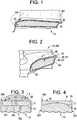
- a turbine bucket platform component 10 (hereinafter referred to as a "component 10") of, for example, a turbine is provided and includes a first surface 20, a second surface 40 and TBC 60.
- the second surface 40 is adjacent to and oriented transversely with respect to the first surface 20 such that an interface zone 45, which is formed where the first and second surfaces 20, 40 meet, is angular. More particularly, the interface zone 45 may be right angular or, in some cases, sharply or acutely angular.
- the second surface 40 has a pocket 50 formed therein to define a rib 55 along a periphery thereof.
- the TBC 60 is respectively applied to the first surface 20 and to the second surface 40 at the pocket 50 such that less than 100% of the second surface 40 is covered and the rib 55 is interposed between the TBC 60 of each of the first and second surfaces 20, 40 and such that the separate portions of the TBC 60 of each of the first and second surfaces 20, 40 are substantially isolated from one another.
- the separation between the separate portions of the TBC 60 of each of the first and second surfaces 20, 40 provides heat flux directional control not otherwise available.
- the component 10 may be any component of a turbine or a gas or steam turbine in which high energy fluids are expanded for power generation purposes.
- the first and second surfaces 20, 40 may each include surfaces facing a gas path along which fluids having relatively high temperatures flow. In general, such relatively high fluid temperatures occur where the fluid temperatures exceed the temperatures of the interior of the component 10 such that the TBC 60 prevents heat flux from the fluid into the component 10 and such that interior temperatures of the component 10 can be maintained below predefined levels.
- the component 10 may be a turbine bucket platform 100 of a gas turbine engine.
- the first surface 20 includes a surface 101 of the turbine bucket platform 100 that faces a hot gas path.
- the second surface 40 may include at least one of a surface of a slashface 102, which is disposed adjacent to the surface 101 of the turbine bucket platform 100, and an aft trench cavity facing surface 104 of the turbine bucket platform 100.
- a depth of the pocket 50 may be uniform, varied, incrementally variable or continuously variable as measured from a plane of a distal edge 555 of the rib 55. That is, as shown in FIG. 3 , the pocket 50 depth, D, may be substantially uniform. In contrast, as shown in FIG. 4 , the pocket 50 depth, D, may be greatest or deepest proximate to at least one of a leading and a trailing edge 200, 201 of the first surface 20 where fluid temperatures may be expected to be highest and where heat flux into the component 10 may be expected to be greatest. Similarly, the pocket 50 depth, D, may be shallowest near a center of the pocket 50 where fluid temperatures may be expected to be lowest and where heat flux into the component 10 may be expected to be lowest.
- the TBC 60 of the second surface 40 may be formed as a single continuous coating or as non-continuous sections 601 and 602.
- the non-continuous sections 601, 602 may all have similar thicknesses or they may have differing thicknesses to control air flow, gap size (see mate face gap, G, of FIG. 5 ) or heat flux into the underlying portions of the second surface 40.
- the second surface 40 may be formed to define an active cooling section, such as a microchannel 402. This microchannel 402 leads toward a backside of the TBC 60 of the second surface 40 and thereby provides cooling flow to the TBC 60 that may enhance an insulating effect.
- An exposed edge of the rib 55 or another similar component may be available as a sacrificial environment condition indicator whereby the edge can be used as a tuned real-time health monitoring differential with calibration being related to edge and mate face gap, G, dimensions.
- the depth, D, of the pocket 50 may exceed the depth or height of the TBC 60. That is, the pocket 50 may be flush with the plane of the distal edge 555 of the rib 55 or depressed to form a land edge. This land edge may possess curvature to entrain, control or trap cooling flow provided via, for example, film hole 401 within mate face gap, G. Even without such cooling flow, the pocket 50 may still provide for enhanced flow path edge durability.
- the TBC 60 of the second surface 40 is at least one of coplanar with and/or recessed from the plane of the distal edge 555 of the rib 55. As such, the TBC 60 of the second surface 40 is isolated and separated from the TBC 60 of the first surface 20.
- the TBC 60 of the first surface 20 and the TBC 60 of the second surface 40 need not be made of the same materials, need not be formed simultaneously and need not be formed over the interface zone 45.
- the TBCs 60 therefore do not tend to deteriorate, crack or peel away at the interface zone 45 and expose the materials of the distal edge 555.
- the exposed materials of the distal edge 555 can be tested for various concerns, such as temperature profiles of the component 10. This testing may be conducted, for example, by way of infrared (IR) imaging of the distal edge 555.
- IR infrared
- the depth, D, of the pocket 50 may be less than that of the TBC 60 such that the TBC 60 of the second surface 40 protrudes from the plane of the distal edge 555 of the rib 55.
- dimensions of the mate face gap, G can be additionally controlled.
- the rib 55 can be defined as a singular feature or as a plurality of ribs 551. Where the rib 55 is defined as a plurality of ribs 551, the plurality of ribs 551 may be arranged to restrict hot gas ingestion, to restrict undesired gas flow direction and/or to guide desired gas flow direction in the mate face gap, G.
- a method includes applying a thermal barrier coating (TBC) 60 to a first surface 20 (operation 500), forming a pocket 50 in a second surface 40 that is adjacent to and oriented transversely with respect to the first surface 20 to thereby define a rib 55 along a periphery of the pocket 50 (operation 510) and applying TBC 60 to the second surface 40 at the pocket 50 such that the rib 55 is interposed between the TBC 60 of the first and second surfaces 20, 40 (operation 520).
- TBC thermal barrier coating
- the forming of the pocket 50 of operation 510 may include at least one or more of electro-dynamic machining (EDM), milling, casting, grinding and/or another similar process.
- the forming of the pocket 50 of operation 510 may also include forming the pocket 50 with a substantially uniform depth, D, or forming the pocket 50 in accordance with a heat flux characteristic of the component 10.
- the depth, D, of the pocket 50 may be nonuniform with, for example, a greatest depth, D, proximate to at least one of a leading and a trailing edge 200, 201 of the first surface 20.
- the applying of the TBC 60 to the second surface 40 of operation 520 may include stopping TBC 60 application before the pocket 50 is overfilled.
- the TBCs 60 of the first and second surfaces 20, 40 can be isolated and separated from one another and the distal edge 555 of the rib 55 can be exposed such that, for example, the material of the rib 55 can be tested (operation 530).
Landscapes
- Engineering & Computer Science (AREA)
- Chemical & Material Sciences (AREA)
- Materials Engineering (AREA)
- Mechanical Engineering (AREA)
- General Engineering & Computer Science (AREA)
- Turbine Rotor Nozzle Sealing (AREA)
Applications Claiming Priority (1)
| Application Number | Priority Date | Filing Date | Title |
|---|---|---|---|
| US13/026,873 US8662849B2 (en) | 2011-02-14 | 2011-02-14 | Component of a turbine bucket platform |
Publications (3)
| Publication Number | Publication Date |
|---|---|
| EP2487331A2 true EP2487331A2 (de) | 2012-08-15 |
| EP2487331A3 EP2487331A3 (de) | 2017-03-22 |
| EP2487331B1 EP2487331B1 (de) | 2018-04-11 |
Family
ID=45571460
Family Applications (1)
| Application Number | Title | Priority Date | Filing Date |
|---|---|---|---|
| EP12154947.1A Active EP2487331B1 (de) | 2011-02-14 | 2012-02-10 | Komponente einer Turbinenschaufelplattform |
Country Status (3)
| Country | Link |
|---|---|
| US (1) | US8662849B2 (de) |
| EP (1) | EP2487331B1 (de) |
| CN (1) | CN102678190B (de) |
Families Citing this family (2)
| Publication number | Priority date | Publication date | Assignee | Title |
|---|---|---|---|---|
| EP2918783A1 (de) * | 2014-03-12 | 2015-09-16 | Siemens Aktiengesellschaft | Turbinenschaufel mit einer beschichteten Plattform |
| US11346227B2 (en) * | 2019-12-19 | 2022-05-31 | Power Systems Mfg., Llc | Modular components for gas turbine engines and methods of manufacturing the same |
Family Cites Families (17)
| Publication number | Priority date | Publication date | Assignee | Title |
|---|---|---|---|---|
| US4872812A (en) * | 1987-08-05 | 1989-10-10 | General Electric Company | Turbine blade plateform sealing and vibration damping apparatus |
| US6670046B1 (en) | 2000-08-31 | 2003-12-30 | Siemens Westinghouse Power Corporation | Thermal barrier coating system for turbine components |
| JP2002266603A (ja) * | 2001-03-06 | 2002-09-18 | Mitsubishi Heavy Ind Ltd | タービン動翼、タービン静翼、タービン用分割環、及び、ガスタービン |
| US6461107B1 (en) * | 2001-03-27 | 2002-10-08 | General Electric Company | Turbine blade tip having thermal barrier coating-formed micro cooling channels |
| US8357454B2 (en) | 2001-08-02 | 2013-01-22 | Siemens Energy, Inc. | Segmented thermal barrier coating |
| GB2413160B (en) * | 2004-04-17 | 2006-08-09 | Rolls Royce Plc | Turbine rotor blades |
| US20060051212A1 (en) * | 2004-09-08 | 2006-03-09 | O'brien Timothy | Coated turbine blade, turbine wheel with plurality of coated turbine blades, and process of coating turbine blade |
| US7168921B2 (en) * | 2004-11-18 | 2007-01-30 | General Electric Company | Cooling system for an airfoil |
| US20060110254A1 (en) * | 2004-11-24 | 2006-05-25 | General Electric Company | Thermal barrier coating for turbine bucket platform side faces and methods of application |
| GB2421032A (en) * | 2004-12-11 | 2006-06-14 | Siemens Ind Turbomachinery Ltd | A method of protecting a component against hot corrosion |
| US7922455B2 (en) * | 2005-09-19 | 2011-04-12 | General Electric Company | Steam-cooled gas turbine bucker for reduced tip leakage loss |
| US7244101B2 (en) * | 2005-10-04 | 2007-07-17 | General Electric Company | Dust resistant platform blade |
| US7309212B2 (en) | 2005-11-21 | 2007-12-18 | General Electric Company | Gas turbine bucket with cooled platform leading edge and method of cooling platform leading edge |
| US7842402B2 (en) * | 2006-03-31 | 2010-11-30 | General Electric Company | Machine components and methods of fabricating |
| US8016549B2 (en) * | 2006-07-13 | 2011-09-13 | United Technologies Corporation | Turbine engine alloys and crystalline orientations |
| US7645123B1 (en) | 2006-11-16 | 2010-01-12 | Florida Turbine Technologies, Inc. | Turbine blade with TBC removed from blade tip region |
| DE102009007164A1 (de) | 2009-02-03 | 2010-08-12 | Rolls-Royce Deutschland Ltd & Co Kg | Verfahren zum Ausbilden einer Kühlluftöffnung in einer Wand einer Gasturbinenbrennkammer sowie nach dem Verfahren hergestellte Brennkammerwand |
-
2011
- 2011-02-14 US US13/026,873 patent/US8662849B2/en active Active
-
2012
- 2012-02-10 EP EP12154947.1A patent/EP2487331B1/de active Active
- 2012-02-14 CN CN201210040480.5A patent/CN102678190B/zh active Active
Non-Patent Citations (1)
| Title |
|---|
| None |
Also Published As
| Publication number | Publication date |
|---|---|
| EP2487331A3 (de) | 2017-03-22 |
| CN102678190A (zh) | 2012-09-19 |
| EP2487331B1 (de) | 2018-04-11 |
| US20120207613A1 (en) | 2012-08-16 |
| US8662849B2 (en) | 2014-03-04 |
| CN102678190B (zh) | 2015-12-16 |
Similar Documents
| Publication | Publication Date | Title |
|---|---|---|
| US9835088B2 (en) | Cooled wall | |
| EP3088675B1 (de) | Laufschaufel und zugehörige gasturbine | |
| EP3088679A1 (de) | Dichtung für eine gasturbinenmotorbaugruppe | |
| EP3012531A1 (de) | Hybride durchgangslöcher und angewinkelte löcher zur brennertüllenkühlung | |
| EP2657451A2 (de) | Turbinenummantelungskühlanordnung für eine Gasturbinenanlage | |
| US20070048135A1 (en) | Turbine vane construction | |
| EP3039249B1 (de) | Mateface-oberflächen mit einer geometrie auf einer turbomaschinen-hardware | |
| US10364683B2 (en) | Gas turbine engine component cooling passage turbulator | |
| US7922455B2 (en) | Steam-cooled gas turbine bucker for reduced tip leakage loss | |
| EP3299586A1 (de) | Dichtung in einem gasturbinenkraftwerk und zugehöriges herstellungsverfahren | |
| US10082033B2 (en) | Gas turbine blade with platform cooling | |
| US8585350B1 (en) | Turbine vane with trailing edge extension | |
| EP3090143A1 (de) | Gasturbinenmotorkomponentenanschlussflächenoberflächen | |
| EP2487331B1 (de) | Komponente einer Turbinenschaufelplattform | |
| US10392945B2 (en) | Turbomachine cooling system | |
| US10036255B2 (en) | Technique for cooling a root side of a platform of a turbomachine part | |
| EP2716876A1 (de) | Gekühlte Dichtungsanordnung | |
| KR20190008104A (ko) | 터보기계의 충돌 냉각 인서트 | |
| JP2013139792A (ja) | タービン構成要素間の流体流れを減少させるためのタービン組立体および方法 | |
| EP3165713A1 (de) | Turbinenschaufel | |
| US9200534B2 (en) | Turbine nozzle having non-linear cooling conduit | |
| EP3323978B1 (de) | Turbinenanordnung | |
| US20160298465A1 (en) | Gas turbine engine component cooling passage with asymmetrical pedestals | |
| US9581037B2 (en) | Seals with cooling pathways and metered cooling | |
| WO2019245546A1 (en) | Cooled turbine blade assembly, corresponding methods for cooling and manufacturing |
Legal Events
| Date | Code | Title | Description |
|---|---|---|---|
| PUAI | Public reference made under article 153(3) epc to a published international application that has entered the european phase |
Free format text: ORIGINAL CODE: 0009012 |
|
| AK | Designated contracting states |
Kind code of ref document: A2 Designated state(s): AL AT BE BG CH CY CZ DE DK EE ES FI FR GB GR HR HU IE IS IT LI LT LU LV MC MK MT NL NO PL PT RO RS SE SI SK SM TR |
|
| AX | Request for extension of the european patent |
Extension state: BA ME |
|
| PUAL | Search report despatched |
Free format text: ORIGINAL CODE: 0009013 |
|
| AK | Designated contracting states |
Kind code of ref document: A3 Designated state(s): AL AT BE BG CH CY CZ DE DK EE ES FI FR GB GR HR HU IE IS IT LI LT LU LV MC MK MT NL NO PL PT RO RS SE SI SK SM TR |
|
| AX | Request for extension of the european patent |
Extension state: BA ME |
|
| RIC1 | Information provided on ipc code assigned before grant |
Ipc: F01D 5/28 20060101AFI20170215BHEP |
|
| STAA | Information on the status of an ep patent application or granted ep patent |
Free format text: STATUS: REQUEST FOR EXAMINATION WAS MADE |
|
| 17P | Request for examination filed |
Effective date: 20170922 |
|
| RBV | Designated contracting states (corrected) |
Designated state(s): AL AT BE BG CH CY CZ DE DK EE ES FI FR GB GR HR HU IE IS IT LI LT LU LV MC MK MT NL NO PL PT RO RS SE SI SK SM TR |
|
| GRAP | Despatch of communication of intention to grant a patent |
Free format text: ORIGINAL CODE: EPIDOSNIGR1 |
|
| STAA | Information on the status of an ep patent application or granted ep patent |
Free format text: STATUS: GRANT OF PATENT IS INTENDED |
|
| INTG | Intention to grant announced |
Effective date: 20171110 |
|
| GRAS | Grant fee paid |
Free format text: ORIGINAL CODE: EPIDOSNIGR3 |
|
| GRAA | (expected) grant |
Free format text: ORIGINAL CODE: 0009210 |
|
| STAA | Information on the status of an ep patent application or granted ep patent |
Free format text: STATUS: THE PATENT HAS BEEN GRANTED |
|
| AK | Designated contracting states |
Kind code of ref document: B1 Designated state(s): AL AT BE BG CH CY CZ DE DK EE ES FI FR GB GR HR HU IE IS IT LI LT LU LV MC MK MT NL NO PL PT RO RS SE SI SK SM TR |
|
| REG | Reference to a national code |
Ref country code: GB Ref legal event code: FG4D |
|
| REG | Reference to a national code |
Ref country code: CH Ref legal event code: EP |
|
| REG | Reference to a national code |
Ref country code: AT Ref legal event code: REF Ref document number: 988245 Country of ref document: AT Kind code of ref document: T Effective date: 20180415 |
|
| REG | Reference to a national code |
Ref country code: IE Ref legal event code: FG4D |
|
| REG | Reference to a national code |
Ref country code: DE Ref legal event code: R096 Ref document number: 602012044955 Country of ref document: DE |
|
| REG | Reference to a national code |
Ref country code: NL Ref legal event code: MP Effective date: 20180411 |
|
| REG | Reference to a national code |
Ref country code: LT Ref legal event code: MG4D |
|
| PG25 | Lapsed in a contracting state [announced via postgrant information from national office to epo] |
Ref country code: NL Free format text: LAPSE BECAUSE OF FAILURE TO SUBMIT A TRANSLATION OF THE DESCRIPTION OR TO PAY THE FEE WITHIN THE PRESCRIBED TIME-LIMIT Effective date: 20180411 |
|
| PG25 | Lapsed in a contracting state [announced via postgrant information from national office to epo] |
Ref country code: ES Free format text: LAPSE BECAUSE OF FAILURE TO SUBMIT A TRANSLATION OF THE DESCRIPTION OR TO PAY THE FEE WITHIN THE PRESCRIBED TIME-LIMIT Effective date: 20180411 Ref country code: LT Free format text: LAPSE BECAUSE OF FAILURE TO SUBMIT A TRANSLATION OF THE DESCRIPTION OR TO PAY THE FEE WITHIN THE PRESCRIBED TIME-LIMIT Effective date: 20180411 Ref country code: PL Free format text: LAPSE BECAUSE OF FAILURE TO SUBMIT A TRANSLATION OF THE DESCRIPTION OR TO PAY THE FEE WITHIN THE PRESCRIBED TIME-LIMIT Effective date: 20180411 Ref country code: SE Free format text: LAPSE BECAUSE OF FAILURE TO SUBMIT A TRANSLATION OF THE DESCRIPTION OR TO PAY THE FEE WITHIN THE PRESCRIBED TIME-LIMIT Effective date: 20180411 Ref country code: NO Free format text: LAPSE BECAUSE OF FAILURE TO SUBMIT A TRANSLATION OF THE DESCRIPTION OR TO PAY THE FEE WITHIN THE PRESCRIBED TIME-LIMIT Effective date: 20180711 Ref country code: BG Free format text: LAPSE BECAUSE OF FAILURE TO SUBMIT A TRANSLATION OF THE DESCRIPTION OR TO PAY THE FEE WITHIN THE PRESCRIBED TIME-LIMIT Effective date: 20180711 Ref country code: AL Free format text: LAPSE BECAUSE OF FAILURE TO SUBMIT A TRANSLATION OF THE DESCRIPTION OR TO PAY THE FEE WITHIN THE PRESCRIBED TIME-LIMIT Effective date: 20180411 Ref country code: FI Free format text: LAPSE BECAUSE OF FAILURE TO SUBMIT A TRANSLATION OF THE DESCRIPTION OR TO PAY THE FEE WITHIN THE PRESCRIBED TIME-LIMIT Effective date: 20180411 |
|
| PG25 | Lapsed in a contracting state [announced via postgrant information from national office to epo] |
Ref country code: HR Free format text: LAPSE BECAUSE OF FAILURE TO SUBMIT A TRANSLATION OF THE DESCRIPTION OR TO PAY THE FEE WITHIN THE PRESCRIBED TIME-LIMIT Effective date: 20180411 Ref country code: GR Free format text: LAPSE BECAUSE OF FAILURE TO SUBMIT A TRANSLATION OF THE DESCRIPTION OR TO PAY THE FEE WITHIN THE PRESCRIBED TIME-LIMIT Effective date: 20180712 Ref country code: LV Free format text: LAPSE BECAUSE OF FAILURE TO SUBMIT A TRANSLATION OF THE DESCRIPTION OR TO PAY THE FEE WITHIN THE PRESCRIBED TIME-LIMIT Effective date: 20180411 Ref country code: RS Free format text: LAPSE BECAUSE OF FAILURE TO SUBMIT A TRANSLATION OF THE DESCRIPTION OR TO PAY THE FEE WITHIN THE PRESCRIBED TIME-LIMIT Effective date: 20180411 |
|
| REG | Reference to a national code |
Ref country code: AT Ref legal event code: MK05 Ref document number: 988245 Country of ref document: AT Kind code of ref document: T Effective date: 20180411 |
|
| PG25 | Lapsed in a contracting state [announced via postgrant information from national office to epo] |
Ref country code: PT Free format text: LAPSE BECAUSE OF FAILURE TO SUBMIT A TRANSLATION OF THE DESCRIPTION OR TO PAY THE FEE WITHIN THE PRESCRIBED TIME-LIMIT Effective date: 20180813 |
|
| REG | Reference to a national code |
Ref country code: DE Ref legal event code: R097 Ref document number: 602012044955 Country of ref document: DE |
|
| PG25 | Lapsed in a contracting state [announced via postgrant information from national office to epo] |
Ref country code: SK Free format text: LAPSE BECAUSE OF FAILURE TO SUBMIT A TRANSLATION OF THE DESCRIPTION OR TO PAY THE FEE WITHIN THE PRESCRIBED TIME-LIMIT Effective date: 20180411 Ref country code: DK Free format text: LAPSE BECAUSE OF FAILURE TO SUBMIT A TRANSLATION OF THE DESCRIPTION OR TO PAY THE FEE WITHIN THE PRESCRIBED TIME-LIMIT Effective date: 20180411 Ref country code: CZ Free format text: LAPSE BECAUSE OF FAILURE TO SUBMIT A TRANSLATION OF THE DESCRIPTION OR TO PAY THE FEE WITHIN THE PRESCRIBED TIME-LIMIT Effective date: 20180411 Ref country code: EE Free format text: LAPSE BECAUSE OF FAILURE TO SUBMIT A TRANSLATION OF THE DESCRIPTION OR TO PAY THE FEE WITHIN THE PRESCRIBED TIME-LIMIT Effective date: 20180411 Ref country code: AT Free format text: LAPSE BECAUSE OF FAILURE TO SUBMIT A TRANSLATION OF THE DESCRIPTION OR TO PAY THE FEE WITHIN THE PRESCRIBED TIME-LIMIT Effective date: 20180411 Ref country code: RO Free format text: LAPSE BECAUSE OF FAILURE TO SUBMIT A TRANSLATION OF THE DESCRIPTION OR TO PAY THE FEE WITHIN THE PRESCRIBED TIME-LIMIT Effective date: 20180411 |
|
| PLBE | No opposition filed within time limit |
Free format text: ORIGINAL CODE: 0009261 |
|
| STAA | Information on the status of an ep patent application or granted ep patent |
Free format text: STATUS: NO OPPOSITION FILED WITHIN TIME LIMIT |
|
| PG25 | Lapsed in a contracting state [announced via postgrant information from national office to epo] |
Ref country code: SM Free format text: LAPSE BECAUSE OF FAILURE TO SUBMIT A TRANSLATION OF THE DESCRIPTION OR TO PAY THE FEE WITHIN THE PRESCRIBED TIME-LIMIT Effective date: 20180411 |
|
| 26N | No opposition filed |
Effective date: 20190114 |
|
| PG25 | Lapsed in a contracting state [announced via postgrant information from national office to epo] |
Ref country code: SI Free format text: LAPSE BECAUSE OF FAILURE TO SUBMIT A TRANSLATION OF THE DESCRIPTION OR TO PAY THE FEE WITHIN THE PRESCRIBED TIME-LIMIT Effective date: 20180411 |
|
| REG | Reference to a national code |
Ref country code: CH Ref legal event code: PL |
|
| GBPC | Gb: european patent ceased through non-payment of renewal fee |
Effective date: 20190210 |
|
| PG25 | Lapsed in a contracting state [announced via postgrant information from national office to epo] |
Ref country code: LU Free format text: LAPSE BECAUSE OF NON-PAYMENT OF DUE FEES Effective date: 20190210 Ref country code: MC Free format text: LAPSE BECAUSE OF FAILURE TO SUBMIT A TRANSLATION OF THE DESCRIPTION OR TO PAY THE FEE WITHIN THE PRESCRIBED TIME-LIMIT Effective date: 20180411 |
|
| REG | Reference to a national code |
Ref country code: BE Ref legal event code: MM Effective date: 20190228 |
|
| REG | Reference to a national code |
Ref country code: IE Ref legal event code: MM4A |
|
| PG25 | Lapsed in a contracting state [announced via postgrant information from national office to epo] |
Ref country code: LI Free format text: LAPSE BECAUSE OF NON-PAYMENT OF DUE FEES Effective date: 20190228 Ref country code: CH Free format text: LAPSE BECAUSE OF NON-PAYMENT OF DUE FEES Effective date: 20190228 |
|
| PG25 | Lapsed in a contracting state [announced via postgrant information from national office to epo] |
Ref country code: GB Free format text: LAPSE BECAUSE OF NON-PAYMENT OF DUE FEES Effective date: 20190210 Ref country code: IE Free format text: LAPSE BECAUSE OF NON-PAYMENT OF DUE FEES Effective date: 20190210 |
|
| PG25 | Lapsed in a contracting state [announced via postgrant information from national office to epo] |
Ref country code: BE Free format text: LAPSE BECAUSE OF NON-PAYMENT OF DUE FEES Effective date: 20190228 |
|
| PG25 | Lapsed in a contracting state [announced via postgrant information from national office to epo] |
Ref country code: TR Free format text: LAPSE BECAUSE OF FAILURE TO SUBMIT A TRANSLATION OF THE DESCRIPTION OR TO PAY THE FEE WITHIN THE PRESCRIBED TIME-LIMIT Effective date: 20180411 |
|
| PG25 | Lapsed in a contracting state [announced via postgrant information from national office to epo] |
Ref country code: MT Free format text: LAPSE BECAUSE OF NON-PAYMENT OF DUE FEES Effective date: 20190210 |
|
| PGFP | Annual fee paid to national office [announced via postgrant information from national office to epo] |
Ref country code: FR Payment date: 20210120 Year of fee payment: 10 |
|
| PG25 | Lapsed in a contracting state [announced via postgrant information from national office to epo] |
Ref country code: CY Free format text: LAPSE BECAUSE OF FAILURE TO SUBMIT A TRANSLATION OF THE DESCRIPTION OR TO PAY THE FEE WITHIN THE PRESCRIBED TIME-LIMIT Effective date: 20180411 |
|
| PG25 | Lapsed in a contracting state [announced via postgrant information from national office to epo] |
Ref country code: IS Free format text: LAPSE BECAUSE OF FAILURE TO SUBMIT A TRANSLATION OF THE DESCRIPTION OR TO PAY THE FEE WITHIN THE PRESCRIBED TIME-LIMIT Effective date: 20180811 |
|
| PG25 | Lapsed in a contracting state [announced via postgrant information from national office to epo] |
Ref country code: HU Free format text: LAPSE BECAUSE OF FAILURE TO SUBMIT A TRANSLATION OF THE DESCRIPTION OR TO PAY THE FEE WITHIN THE PRESCRIBED TIME-LIMIT; INVALID AB INITIO Effective date: 20120210 |
|
| PG25 | Lapsed in a contracting state [announced via postgrant information from national office to epo] |
Ref country code: MK Free format text: LAPSE BECAUSE OF FAILURE TO SUBMIT A TRANSLATION OF THE DESCRIPTION OR TO PAY THE FEE WITHIN THE PRESCRIBED TIME-LIMIT Effective date: 20180411 |
|
| PG25 | Lapsed in a contracting state [announced via postgrant information from national office to epo] |
Ref country code: FR Free format text: LAPSE BECAUSE OF NON-PAYMENT OF DUE FEES Effective date: 20220228 |
|
| PGFP | Annual fee paid to national office [announced via postgrant information from national office to epo] |
Ref country code: IT Payment date: 20230120 Year of fee payment: 12 |
|
| REG | Reference to a national code |
Ref country code: DE Ref legal event code: R081 Ref document number: 602012044955 Country of ref document: DE Owner name: GENERAL ELECTRIC TECHNOLOGY GMBH, CH Free format text: FORMER OWNER: GENERAL ELECTRIC COMPANY, SCHENECTADY, NY, US |
|
| PG25 | Lapsed in a contracting state [announced via postgrant information from national office to epo] |
Ref country code: IT Free format text: LAPSE BECAUSE OF NON-PAYMENT OF DUE FEES Effective date: 20240210 |
|
| PGFP | Annual fee paid to national office [announced via postgrant information from national office to epo] |
Ref country code: DE Payment date: 20250122 Year of fee payment: 14 |