EP3088679A1 - Dichtung für eine gasturbinenmotorbaugruppe - Google Patents
Dichtung für eine gasturbinenmotorbaugruppe Download PDFInfo
- Publication number
- EP3088679A1 EP3088679A1 EP16161190.0A EP16161190A EP3088679A1 EP 3088679 A1 EP3088679 A1 EP 3088679A1 EP 16161190 A EP16161190 A EP 16161190A EP 3088679 A1 EP3088679 A1 EP 3088679A1
- Authority
- EP
- European Patent Office
- Prior art keywords
- component
- seal
- leg
- high pressure
- assembly
- Prior art date
- Legal status (The legal status is an assumption and is not a legal conclusion. Google has not performed a legal analysis and makes no representation as to the accuracy of the status listed.)
- Withdrawn
Links
Images
Classifications
-
- F—MECHANICAL ENGINEERING; LIGHTING; HEATING; WEAPONS; BLASTING
- F01—MACHINES OR ENGINES IN GENERAL; ENGINE PLANTS IN GENERAL; STEAM ENGINES
- F01D—NON-POSITIVE DISPLACEMENT MACHINES OR ENGINES, e.g. STEAM TURBINES
- F01D11/00—Preventing or minimising internal leakage of working-fluid, e.g. between stages
- F01D11/005—Sealing means between non relatively rotating elements
-
- F—MECHANICAL ENGINEERING; LIGHTING; HEATING; WEAPONS; BLASTING
- F01—MACHINES OR ENGINES IN GENERAL; ENGINE PLANTS IN GENERAL; STEAM ENGINES
- F01D—NON-POSITIVE DISPLACEMENT MACHINES OR ENGINES, e.g. STEAM TURBINES
- F01D25/00—Component parts, details, or accessories, not provided for in, or of interest apart from, other groups
- F01D25/08—Cooling; Heating; Heat-insulation
- F01D25/14—Casings modified therefor
- F01D25/145—Thermally insulated casings
-
- F—MECHANICAL ENGINEERING; LIGHTING; HEATING; WEAPONS; BLASTING
- F01—MACHINES OR ENGINES IN GENERAL; ENGINE PLANTS IN GENERAL; STEAM ENGINES
- F01D—NON-POSITIVE DISPLACEMENT MACHINES OR ENGINES, e.g. STEAM TURBINES
- F01D25/00—Component parts, details, or accessories, not provided for in, or of interest apart from, other groups
- F01D25/28—Supporting or mounting arrangements, e.g. for turbine casing
-
- F—MECHANICAL ENGINEERING; LIGHTING; HEATING; WEAPONS; BLASTING
- F01—MACHINES OR ENGINES IN GENERAL; ENGINE PLANTS IN GENERAL; STEAM ENGINES
- F01D—NON-POSITIVE DISPLACEMENT MACHINES OR ENGINES, e.g. STEAM TURBINES
- F01D9/00—Stators
- F01D9/02—Nozzles; Nozzle boxes; Stator blades; Guide conduits, e.g. individual nozzles
-
- F—MECHANICAL ENGINEERING; LIGHTING; HEATING; WEAPONS; BLASTING
- F23—COMBUSTION APPARATUS; COMBUSTION PROCESSES
- F23R—GENERATING COMBUSTION PRODUCTS OF HIGH PRESSURE OR HIGH VELOCITY, e.g. GAS-TURBINE COMBUSTION CHAMBERS
- F23R3/00—Continuous combustion chambers using liquid or gaseous fuel
- F23R3/007—Continuous combustion chambers using liquid or gaseous fuel constructed mainly of ceramic components
-
- F—MECHANICAL ENGINEERING; LIGHTING; HEATING; WEAPONS; BLASTING
- F23—COMBUSTION APPARATUS; COMBUSTION PROCESSES
- F23R—GENERATING COMBUSTION PRODUCTS OF HIGH PRESSURE OR HIGH VELOCITY, e.g. GAS-TURBINE COMBUSTION CHAMBERS
- F23R3/00—Continuous combustion chambers using liquid or gaseous fuel
- F23R3/42—Continuous combustion chambers using liquid or gaseous fuel characterised by the arrangement or form of the flame tubes or combustion chambers
- F23R3/60—Support structures; Attaching or mounting means
-
- F—MECHANICAL ENGINEERING; LIGHTING; HEATING; WEAPONS; BLASTING
- F05—INDEXING SCHEMES RELATING TO ENGINES OR PUMPS IN VARIOUS SUBCLASSES OF CLASSES F01-F04
- F05D—INDEXING SCHEME FOR ASPECTS RELATING TO NON-POSITIVE-DISPLACEMENT MACHINES OR ENGINES, GAS-TURBINES OR JET-PROPULSION PLANTS
- F05D2220/00—Application
- F05D2220/30—Application in turbines
- F05D2220/32—Application in turbines in gas turbines
-
- F—MECHANICAL ENGINEERING; LIGHTING; HEATING; WEAPONS; BLASTING
- F05—INDEXING SCHEMES RELATING TO ENGINES OR PUMPS IN VARIOUS SUBCLASSES OF CLASSES F01-F04
- F05D—INDEXING SCHEME FOR ASPECTS RELATING TO NON-POSITIVE-DISPLACEMENT MACHINES OR ENGINES, GAS-TURBINES OR JET-PROPULSION PLANTS
- F05D2240/00—Components
- F05D2240/10—Stators
- F05D2240/11—Shroud seal segments
-
- F—MECHANICAL ENGINEERING; LIGHTING; HEATING; WEAPONS; BLASTING
- F05—INDEXING SCHEMES RELATING TO ENGINES OR PUMPS IN VARIOUS SUBCLASSES OF CLASSES F01-F04
- F05D—INDEXING SCHEME FOR ASPECTS RELATING TO NON-POSITIVE-DISPLACEMENT MACHINES OR ENGINES, GAS-TURBINES OR JET-PROPULSION PLANTS
- F05D2240/00—Components
- F05D2240/35—Combustors or associated equipment
-
- F—MECHANICAL ENGINEERING; LIGHTING; HEATING; WEAPONS; BLASTING
- F05—INDEXING SCHEMES RELATING TO ENGINES OR PUMPS IN VARIOUS SUBCLASSES OF CLASSES F01-F04
- F05D—INDEXING SCHEME FOR ASPECTS RELATING TO NON-POSITIVE-DISPLACEMENT MACHINES OR ENGINES, GAS-TURBINES OR JET-PROPULSION PLANTS
- F05D2240/00—Components
- F05D2240/55—Seals
-
- F—MECHANICAL ENGINEERING; LIGHTING; HEATING; WEAPONS; BLASTING
- F05—INDEXING SCHEMES RELATING TO ENGINES OR PUMPS IN VARIOUS SUBCLASSES OF CLASSES F01-F04
- F05D—INDEXING SCHEME FOR ASPECTS RELATING TO NON-POSITIVE-DISPLACEMENT MACHINES OR ENGINES, GAS-TURBINES OR JET-PROPULSION PLANTS
- F05D2250/00—Geometry
- F05D2250/10—Two-dimensional
- F05D2250/11—Two-dimensional triangular
-
- F—MECHANICAL ENGINEERING; LIGHTING; HEATING; WEAPONS; BLASTING
- F05—INDEXING SCHEMES RELATING TO ENGINES OR PUMPS IN VARIOUS SUBCLASSES OF CLASSES F01-F04
- F05D—INDEXING SCHEME FOR ASPECTS RELATING TO NON-POSITIVE-DISPLACEMENT MACHINES OR ENGINES, GAS-TURBINES OR JET-PROPULSION PLANTS
- F05D2250/00—Geometry
- F05D2250/60—Structure; Surface texture
- F05D2250/61—Structure; Surface texture corrugated
-
- F—MECHANICAL ENGINEERING; LIGHTING; HEATING; WEAPONS; BLASTING
- F05—INDEXING SCHEMES RELATING TO ENGINES OR PUMPS IN VARIOUS SUBCLASSES OF CLASSES F01-F04
- F05D—INDEXING SCHEME FOR ASPECTS RELATING TO NON-POSITIVE-DISPLACEMENT MACHINES OR ENGINES, GAS-TURBINES OR JET-PROPULSION PLANTS
- F05D2250/00—Geometry
- F05D2250/70—Shape
- F05D2250/75—Shape given by its similarity to a letter, e.g. T-shaped
-
- F—MECHANICAL ENGINEERING; LIGHTING; HEATING; WEAPONS; BLASTING
- F05—INDEXING SCHEMES RELATING TO ENGINES OR PUMPS IN VARIOUS SUBCLASSES OF CLASSES F01-F04
- F05D—INDEXING SCHEME FOR ASPECTS RELATING TO NON-POSITIVE-DISPLACEMENT MACHINES OR ENGINES, GAS-TURBINES OR JET-PROPULSION PLANTS
- F05D2260/00—Function
- F05D2260/20—Heat transfer, e.g. cooling
-
- F—MECHANICAL ENGINEERING; LIGHTING; HEATING; WEAPONS; BLASTING
- F05—INDEXING SCHEMES RELATING TO ENGINES OR PUMPS IN VARIOUS SUBCLASSES OF CLASSES F01-F04
- F05D—INDEXING SCHEME FOR ASPECTS RELATING TO NON-POSITIVE-DISPLACEMENT MACHINES OR ENGINES, GAS-TURBINES OR JET-PROPULSION PLANTS
- F05D2300/00—Materials; Properties thereof
- F05D2300/60—Properties or characteristics given to material by treatment or manufacturing
- F05D2300/603—Composites; e.g. fibre-reinforced
- F05D2300/6033—Ceramic matrix composites [CMC]
-
- Y—GENERAL TAGGING OF NEW TECHNOLOGICAL DEVELOPMENTS; GENERAL TAGGING OF CROSS-SECTIONAL TECHNOLOGIES SPANNING OVER SEVERAL SECTIONS OF THE IPC; TECHNICAL SUBJECTS COVERED BY FORMER USPC CROSS-REFERENCE ART COLLECTIONS [XRACs] AND DIGESTS
- Y02—TECHNOLOGIES OR APPLICATIONS FOR MITIGATION OR ADAPTATION AGAINST CLIMATE CHANGE
- Y02T—CLIMATE CHANGE MITIGATION TECHNOLOGIES RELATED TO TRANSPORTATION
- Y02T50/00—Aeronautics or air transport
- Y02T50/60—Efficient propulsion technologies, e.g. for aircraft
Definitions
- the present disclosure relates generally to gas turbine engines, and more specifically to seals used in gas turbine engines.
- Gas turbine engines are used to power aircraft, watercraft, power generators, and the like. Adjacent components in a gas turbine engine are often separated by a small gap. The small gap allows for variations in manufacturing tolerance of the adjacent components and for expansion/contraction of the components that occurs during operation of the gas turbine engine. Expansion and contraction of the adjacent components is typically caused by the selection of different materials for each component or by different temperatures experienced by each component.
- the small gaps between adjacent components may be sealed to prevent the leakage of air through the small gaps during operation of the turbine engine. Seals used to block the leakage of air through the small gaps are sometimes designed to account for changes in the dimension of the gap to be closed.
- the present disclosure may comprise one or more of the following features and combinations thereof.
- a gas turbine engine assembly may include a first component comprising ceramic matrix materials, a second component comprising ceramic matrix materials, and a seal.
- the first component may include a panel arranged to separate a high pressure zone from a low pressure zone and may be formed to include a first chamfer surface that extends from a high pressure surface of the first component facing the high pressure zone to a first side surface of the first component.
- the second component may include a panel arranged to separate the high pressure zone from the low pressure zone and may be formed to include a second chamfer surface that extends from a high pressure surface of the second component facing the high pressure zone to a second side surface of the first component.
- the seal may be arranged in a channel formed by the first chamfer and the second chamfer when the first side surface of the first component is arranged in confronting relation to the second side surface of the second component.
- the seal may have a first seal surface that contacts the first chamfer surface and a second surface that contacts the second chamfer surface.
- the seal may be shaped to be pushed into contact with the first chamfer surface and the second chamfer surface by pressure in the high pressure zone so that the seal resists gasses moving through a gap between the first side surface of the first component and the second side surface of the second component.
- the seal may have a first leg that provides the first seal surface and a second leg that provides the second seal surface.
- the seal may be shaped to form a trough between the first leg and the second leg.
- the seal may be arranged so that the trough is open to the high pressure zone.
- the seal may have a substantially V-shaped cross-section.
- the first leg and the second leg may each have a curved shaped cross-section.
- the seal may be formed to include a bleed feature configured to allow a predetermined amount of gas to pass through the seal.
- the bleed feature may include a plurality of bleed channels formed in the first seal surface and the second seal surface.
- the seal may have a first leg and a second leg that extends from the first leg to form a trough between the first leg and the second leg. The seal may be arranged so that the trough is open to the high pressure zone. Both the first leg and the second leg may be corrugated to form the plurality of bleed channels.
- the bleed feature may include a plurality of holes formed in the seal.
- the plurality of holes may be arranged about midway between the first seal surface and the second seal surface.
- the first chamfer surface may extend only partway along the first side surface of the panel included in the first component and may be spaced apart from both a forward side surface and an aft side surface of the panel included in the first component.
- the second chamfer surface may extend only partway along the second side surface of the panel included in the second component and may be spaced apart from both a forward side surface and an aft side surface of the panel included in the second component.
- the first component may include a plurality of retention features that extend over corresponding portions of the channel to block the seal from movement out of the channel.
- the second component may include a plurality of retention features that extend over corresponding portions of the channel to block the seal from movement out of the channel.
- the retention features of the first component may be integral to attachment features included in the first component that are configured to couple the panel of the first component to a surrounding structure.
- the retention features of the second component may be integral to attachment features included in the second component that are configured to couple the panel of the second component to a surrounding structure.
- a gas turbine engine assembly may include a first component, a second component, and a seal.
- the first component may include a panel arranged to separate a high pressure zone from a low pressure zone.
- the second component may also include a panel arranged to separate the high pressure zone from the low pressure zone.
- the seal may be arranged in a channel formed between the first component and the second component that opens toward the high pressure zone.
- the seal may have a first seal surface that contacts the first component and a second surface that contacts the second component.
- the seal may be shaped to be pushed into contact with the first component and the second component by pressure in the high pressure zone.
- the seal may have a first leg that provides the first seal surface and a second leg that provides the second seal surface.
- the seal may be shaped to form a trough between the first leg and the second leg.
- the seal may be arranged so that the trough is open to the high pressure zone.
- the seal may have a substantially V-shaped cross-section.
- the first leg and the second leg may each have a curved shaped cross-section.
- the channel may extends only partway along an interface between the first component and the second component.
- the first component may include a plurality of retention features that extend over portions of the channel to block the seal from movement out of the channel.
- the second component may also include a plurality of retention features that extend over portions of the channel to block the seal from movement out of the channel.
- the retention features of the first component may be integral to attachment features included in the first component that are configured to couple the panel of the first component to a surrounding structure.
- the retention features of the second component may be integral to attachment features included in the second component that are configured to couple the panel of the second component to a surrounding structure.
- the seal may be formed to include a bleed feature configured to allow a predetermined amount of gas to pass through the seal.
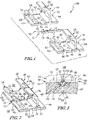
- a pressure-activated seal 10 is adapted to close a gap 11 between first and second adjacent components 20, 30 in a gas turbine engine assembly 50 that separates a high pressure zone HP from a low pressure zone LP as shown in Figs. 1-3 .
- the seal 10 is arranged in a channel 40 formed by the adjacent components 20, 30 that opens toward the high pressure zone HP as shown in Fig. 3 . Gasses in the high pressure zone HP act on the seal 10 to push the seal 10 into contact with the components 20, 30 so that the seal 10 resists gasses moving through the gap 11 between the first component 20 and the second component 30 as shown, for example, in Fig. 3 .
- Each of the components 20, 30 are substantially similar and each includes a panel 22, a first hanger 24, and a second hanger 26 as shown in Figs. 1 and 2 .
- the panel 22 separates the high pressure zone HP from the low pressure zone LP.
- the first and the second hangers 24, 26 are configured to be coupled to structure surrounding the gas turbine engine assembly 50.
- the components 20, 30 are blade track segments made from ceramic matrix materials that may be used with other blade track segments to provide a ring that extends around rotating turbine wheels used in gas turbine engines.
- the components 20, 30 may be made from other materials and/or may be adapted for use as combustor tiles included in the combustor of a gas turbine engine or as heat shields included in other sections of a gas turbine engine.
- the panel 22 of the components 20, 30 is illustratively formed to include a high pressure surface 61 that faces the high pressure zone HP and a low pressure surface 62, opposite the high pressure surface 61, that faces the low pressure zone LP as shown in Figs. 2 and 3 .
- the panel 22 is also formed to include a forward side surface 63, an aft side surface 64, a left side surface 65, and a right side surface 66 as shown in Figs. 1 and 2 .
- the panel 22 is formed to include a left chamfer surface 67 that extends at an angle from the high pressure surface 61 to the left side surface 65 of the panel 22 and a right chamfer surface 68 that extends at an angle from the high pressure surface 61 to the right side surface 66 of the panel 22.
- the chamfer surfaces 67, 68 may be generally flat or barreled (curved).
- the first component 20 and the second component 30 are arranged adjacent to one another so that the right side surface 66 of the first component 20 is in confronting relation with the left side surface 65 of the second component 30 as shown in Fig. 3 .
- the right chamfer surface 68 of the first component 20 then cooperates with the left chamfer surface 67 of the second component 30 to create the channel 40 opening entirely toward the high pressure zone HP that receives the seal 10 as shown in Fig. 3 .
- the chamfer surfaces 67, 68 only extend partway along the corresponding left and right side surfaces 65, 66 and are spaced from the forward and aft surfaces 63, 64; accordingly, the channel 40 only extends partway between and is spaced from the forward and aft surfaces 63, 64 of the panels 22 included in the first and the second components 20, 30.
- the channel 40 is illustratively shaped with straight sides forming a generally triangular space for the seal 10 but may have curved or otherwise shaped sides that provide a space for the seal 10.
- the first and the second hangers 24, 26 are integral with the panels 22 of the first and the second components 20, 30 and are adapted for coupling the panels 22 of the first and the second component 20, 30 with structure surrounding the gas turbine engine assembly 50 as shown in Figs. 1 and 2 .
- the first and the second hangers 24, 26 have a generally L-shape adapted to hang from brackets in a support structure.
- the first and the second hangers may be dovetail shaped, may have pin-receiving holes, or have any other suitable shape for coupling the assembly 50 with other structures.
- first and second hangers 24, 26 each extend over a portion of the channel 40 to provide retention tabs 74, 76 as shown in Figs. 1-3 .
- the retention tabs 74, 76 provide features that block the seal 10 from movement out of the channel 40 toward the high pressure zone HP (e.g. when the zones HP, LP around the assembly 50 are not pressurized by operation of a gas turbine engine).
- the retention tabs 74, 76 may be independent of the first and the second hangers 24, 26 while still being integrated with the panels 22 of the first and the second components 20, 30.
- the seal 10 illustratively comprises a sheet of metallic materials having a substantially constant thickness as shown in Figs. 3 and 4 . While the seal 10 is illustratively shown as a metallic component, it may also be made from other materials including but not limited to ceramic-containing materials.
- the seal 10 is formed or bent to include a first leg 12 and a second leg 14 that cooperate to form a trough 16 opening in its entirety toward the high pressure zone HP.
- the legs 12, 14 illustratively extend from one another so that the seal 10 has a generally V-shaped cross section but may be spaced apart by an intervening member in some embodiments. In other embodiments, a floor may extend between the legs 12, 14 so that the legs 12, 14 are spaced apart from one another.
- the first leg 12 provides a first sealing surface 13 that contacts the right chamfer surface 68 of the first component 20 when pushed by gas in the high pressure zone HP.
- the second leg 14 provides a second sealing surface 15 that contacts the left chamfer surface 67 of the second component 30 when pushed by gas in the high pressure zone HP.
- the seal 10 may include optional holes 18 that provide a bleed feature for allowing a predetermined amount of flow to move through the seal 10 as shown in Figs. 3 and 4 .
- the holes 18 may be arranged about midway between the first and the second components 20, 30 at the intersection of the first and the second legs 12, 14. In other embodiments, the holes 18 may be arranged at a different location.
- cooling air can flow through small gaps 11 between components.
- the small gaps accelerate flow velocity and can create high local cooling effect.
- the localized cooling can generate high temperature gradients and thermal stresses. Due to the high strength of metallic alloys, such components can withstand the resulting thermal stresses.
- components comprising ceramic matrix materials may require sealing like that provided by the pressure activated seal 10 disclosed herein.
- Ceramic matrix composite containing components often offer higher temperature capability than the metallic alloys and they are being investigated for applications in turbine vanes, seal segments, and blades. CMCs, however, can require protection from water vapor attack through an environmental barrier coating (EBC). Because of the small dimensions of strip seal grooves, it may be hard to deposit quality coating inside strip seal grooves using air plasma spray and to machine the grooves. Accordingly, the design of alternative features for locating seals in assemblies including CMCs can be desirable.
- EBC environmental barrier coating
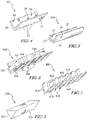
- a second illustrative seal 210 adapted for use in place of the seal 10 as part of the gas turbine engine assembly 50 is shown in Fig. 5 .
- the seal 210 illustratively comprises metallic materials and includes a first leg 212 and a second leg 214 that cooperate to form a trough 216.
- the legs 212, 214 illustratively extend from one another but may be spaced apart by an intervening member in some embodiments.
- the first leg 212 provides a first sealing surface 213 that would contact the right chamfer surface 68 of the first component 20 when pushed by gas in the high pressure zone HP.
- the second leg 214 provides a second sealing surface 215 that would contact the left chamfer surface 67 of the second component 30 when pushed by gas in the high pressure zone HP.
- the legs 212, 214 are barreled or curved to encourage sealing contact when assembled with the components 20, 30 of the assembly 50. While the seal 210 is illustratively shown as a metallic component, it may also be made from other materials including but not limited to ceramic-containing materials.
- a third illustrative seal 310 adapted for use in place of the seal 10 as part of the gas turbine engine assembly 50 is shown in Fig. 6 .
- the seal 310 illustratively comprises metallic materials and includes a first leg 312 and a second leg 314 that cooperate to form a trough 316.
- the legs 312, 314 illustratively extend from one another so that the seal 310 forms a V-shaped cross section but may be spaced apart by an intervening member in some embodiments.
- the first leg 312 provides sealing surfaces 313 that would contact the right chamfer surface 68 of the first component 20 when pushed by gas in the high pressure zone HP.
- the second leg 314 provides sealing surfaces 315 that would contact the left chamfer surface 67 of the second component 30 when pushed by gas in the high pressure zone HP.
- the legs 312, 314 are formed to include bleed channels 318 that provide a bleed feature for allowing a predetermined amount of flow through the seal 310 when used with the components 20, 30 in the assembly 50. While the seal 310 is illustratively shown as a metallic component, it may also be made from other materials including but not limited to ceramic-containing materials.
- a fourth illustrative seal 410 adapted for use in place of the seal 10 as part of the gas turbine engine assembly 50 is shown in Fig. 7 .
- the seal 410 illustratively comprises metallic materials and includes a first leg 412 and a second leg 414 that cooperate to form a trough 416.
- the legs 412, 414 illustratively extend from one another so that the seal 410 forms a V-shaped cross section but may be spaced apart by an intervening member in some embodiments.
- the first leg 412 provides sealing surfaces 413 that would contact the right chamfer surface 68 of the first component 20 when pushed by gas in the high pressure zone HP.
- the second leg 414 provides sealing surfaces 215 that would contact the left chamfer surface 67 of the second component 30 when pushed by gas in the high pressure zone HP.
- the legs 412, 414 are corrugated to include bleed channels 418 that provide a bleed feature for allowing a predetermined amount of flow through the seal 410 when used with the components 20, 40 in the assembly 50. While the seal 410 is illustratively shown as a metallic component, it may also be made from other materials including but not limited to ceramic-containing materials.
- a fifth illustrative seal 510 adapted for use in place of the seal 10 as part of the gas turbine engine assembly 50 is shown in Fig. 8 .
- the seal 510 illustratively comprises metallic materials and has a generally triangular cross section.
- the seal 510 provides sealing surfaces 513, 515 that would contact the chamfer surfaces 67, 68 of the components 20, 30 when pushed by gas in the high pressure zone HP. While the seal 510 is illustratively shown as a metallic component, it may also be made from other materials including but not limited to ceramic-containing materials.
Applications Claiming Priority (1)
| Application Number | Priority Date | Filing Date | Title |
|---|---|---|---|
| US201562155216P | 2015-04-30 | 2015-04-30 |
Publications (1)
| Publication Number | Publication Date |
|---|---|
| EP3088679A1 true EP3088679A1 (de) | 2016-11-02 |
Family
ID=55586236
Family Applications (1)
| Application Number | Title | Priority Date | Filing Date |
|---|---|---|---|
| EP16161190.0A Withdrawn EP3088679A1 (de) | 2015-04-30 | 2016-03-18 | Dichtung für eine gasturbinenmotorbaugruppe |
Country Status (3)
| Country | Link |
|---|---|
| US (1) | US10704404B2 (de) |
| EP (1) | EP3088679A1 (de) |
| CA (1) | CA2924933A1 (de) |
Cited By (1)
| Publication number | Priority date | Publication date | Assignee | Title |
|---|---|---|---|---|
| EP3819474A1 (de) * | 2019-11-07 | 2021-05-12 | Raytheon Technologies Corporation | Plattformdichtung für ein gasturbinentriebwerk |
Families Citing this family (14)
| Publication number | Priority date | Publication date | Assignee | Title |
|---|---|---|---|---|
| US20170276000A1 (en) * | 2016-03-24 | 2017-09-28 | General Electric Company | Apparatus and method for forming apparatus |
| FR3055148B1 (fr) * | 2016-08-19 | 2020-06-05 | Safran Aircraft Engines | Ensemble d'anneau de turbine |
| FR3055147B1 (fr) * | 2016-08-19 | 2020-05-29 | Safran Aircraft Engines | Ensemble d'anneau de turbine |
| US10718226B2 (en) * | 2017-11-21 | 2020-07-21 | Rolls-Royce Corporation | Ceramic matrix composite component assembly and seal |
| US10934873B2 (en) * | 2018-11-07 | 2021-03-02 | General Electric Company | Sealing system for turbine shroud segments |
| US10815810B2 (en) * | 2019-01-10 | 2020-10-27 | Raytheon Technologies Corporation | BOAS assemblies with axial support pins |
| US11255208B2 (en) * | 2019-05-15 | 2022-02-22 | Raytheon Technologies Corporation | Feather seal for CMC BOAS |
| US11365644B2 (en) | 2019-07-01 | 2022-06-21 | Raytheon Technologies Corporation | Double box boas and carrier system |
| US11073037B2 (en) * | 2019-07-19 | 2021-07-27 | Raytheon Technologies Corporation | CMC BOAS arrangement |
| US11248482B2 (en) | 2019-07-19 | 2022-02-15 | Raytheon Technologies Corporation | CMC BOAS arrangement |
| US11105214B2 (en) | 2019-07-19 | 2021-08-31 | Raytheon Technologies Corporation | CMC BOAS arrangement |
| US11073038B2 (en) | 2019-07-19 | 2021-07-27 | Raytheon Technologies Corporation | CMC BOAS arrangement |
| US20220290573A1 (en) * | 2021-03-09 | 2022-09-15 | Raytheon Technologies Corporation | Chevron grooved mateface seal |
| CN113074386B (zh) * | 2021-03-17 | 2022-08-16 | 中国航发动力股份有限公司 | 一种隔热屏安装用辅助装置及隔热屏安装方法 |
Citations (6)
| Publication number | Priority date | Publication date | Assignee | Title |
|---|---|---|---|---|
| US3728041A (en) * | 1971-10-04 | 1973-04-17 | Gen Electric | Fluidic seal for segmented nozzle diaphragm |
| US5088888A (en) * | 1990-12-03 | 1992-02-18 | General Electric Company | Shroud seal |
| US5338152A (en) * | 1992-05-11 | 1994-08-16 | Mtu Motoren- Und Turbinen-Union Muenchen Gmbh | Arrangement for sealing structural members using a V-shaped insert, particularly in the case of turbo-engines |
| GB2280935A (en) * | 1993-06-12 | 1995-02-15 | Rolls Royce Plc | Cooled sealing strip for nozzle guide vane segments |
| US20040165983A1 (en) * | 2003-02-26 | 2004-08-26 | Rolls-Royce Plc | Damper seal |
| JP2013155681A (ja) * | 2012-01-31 | 2013-08-15 | Hitachi Ltd | シール構造及びシール構造を用いたガスタービン |
Family Cites Families (11)
| Publication number | Priority date | Publication date | Assignee | Title |
|---|---|---|---|---|
| US5458343A (en) | 1994-08-11 | 1995-10-17 | General Electric Company | Aircraft engine firewall seal |
| US5513955A (en) * | 1994-12-14 | 1996-05-07 | United Technologies Corporation | Turbine engine rotor blade platform seal |
| US5709530A (en) | 1996-09-04 | 1998-01-20 | United Technologies Corporation | Gas turbine vane seal |
| US6273683B1 (en) | 1999-02-05 | 2001-08-14 | Siemens Westinghouse Power Corporation | Turbine blade platform seal |
| US6893214B2 (en) | 2002-12-20 | 2005-05-17 | General Electric Company | Shroud segment and assembly with surface recessed seal bridging adjacent members |
| US7771159B2 (en) | 2006-10-16 | 2010-08-10 | General Electric Company | High temperature seals and high temperature sealing systems |
| FR2909998B1 (fr) | 2006-12-18 | 2009-03-06 | Snecma Propulsion Solide Sa | Piece en materiau composite a matrice ceramique contenant du silicium, protegee contre la corrosion |
| US7798769B2 (en) | 2007-02-15 | 2010-09-21 | Siemens Energy, Inc. | Flexible, high-temperature ceramic seal element |
| US8206087B2 (en) * | 2008-04-11 | 2012-06-26 | Siemens Energy, Inc. | Sealing arrangement for turbine engine having ceramic components |
| US8132442B2 (en) | 2008-09-22 | 2012-03-13 | Siemens Energy, Inc. | Compressible ceramic seal |
| US8534995B2 (en) | 2009-03-05 | 2013-09-17 | United Technologies Corporation | Turbine engine sealing arrangement |
-
2016
- 2016-03-18 EP EP16161190.0A patent/EP3088679A1/de not_active Withdrawn
- 2016-03-21 US US15/076,127 patent/US10704404B2/en active Active
- 2016-03-24 CA CA2924933A patent/CA2924933A1/en not_active Abandoned
Patent Citations (6)
| Publication number | Priority date | Publication date | Assignee | Title |
|---|---|---|---|---|
| US3728041A (en) * | 1971-10-04 | 1973-04-17 | Gen Electric | Fluidic seal for segmented nozzle diaphragm |
| US5088888A (en) * | 1990-12-03 | 1992-02-18 | General Electric Company | Shroud seal |
| US5338152A (en) * | 1992-05-11 | 1994-08-16 | Mtu Motoren- Und Turbinen-Union Muenchen Gmbh | Arrangement for sealing structural members using a V-shaped insert, particularly in the case of turbo-engines |
| GB2280935A (en) * | 1993-06-12 | 1995-02-15 | Rolls Royce Plc | Cooled sealing strip for nozzle guide vane segments |
| US20040165983A1 (en) * | 2003-02-26 | 2004-08-26 | Rolls-Royce Plc | Damper seal |
| JP2013155681A (ja) * | 2012-01-31 | 2013-08-15 | Hitachi Ltd | シール構造及びシール構造を用いたガスタービン |
Cited By (2)
| Publication number | Priority date | Publication date | Assignee | Title |
|---|---|---|---|---|
| EP3819474A1 (de) * | 2019-11-07 | 2021-05-12 | Raytheon Technologies Corporation | Plattformdichtung für ein gasturbinentriebwerk |
| US11187096B2 (en) | 2019-11-07 | 2021-11-30 | Raytheon Technologies Corporation | Platform seal |
Also Published As
| Publication number | Publication date |
|---|---|
| US20160319686A1 (en) | 2016-11-03 |
| US10704404B2 (en) | 2020-07-07 |
| CA2924933A1 (en) | 2016-10-30 |
Similar Documents
| Publication | Publication Date | Title |
|---|---|---|
| US10704404B2 (en) | Seals for a gas turbine engine assembly | |
| US9759079B2 (en) | Split line flow path seals | |
| US10718226B2 (en) | Ceramic matrix composite component assembly and seal | |
| US10329950B2 (en) | Nozzle guide vane with composite heat shield | |
| EP3327254B1 (de) | Dichtungsanordnung für gasturbinenmotorkomponenten | |
| EP3348792B1 (de) | Dichtungsanordnung für gasturbinenmotorkomponenten | |
| EP3045685B1 (de) | Mechanische verbindung und zugehörige leitschaufelbefestigungsanordnung | |
| US9784115B2 (en) | Blade track assembly, components, and methods | |
| EP2846097B1 (de) | Gasturbinen-Brennkammer mit Kacheln mit Filmkühlungslöchern | |
| US8556578B1 (en) | Spring loaded compliant seal for high temperature use | |
| JP2007107524A (ja) | セラミックマトリックス複合物体内の熱応力を制御するアセンブリ | |
| EP3093448B1 (de) | Wärmeisolierte turbinenmantelanordnung | |
| US10662795B2 (en) | Rotary assembly for a turbomachine | |
| EP3076078B1 (de) | Brennkammerkonfigurationen für einen gasturbinenmotor | |
| EP3009745A1 (de) | Schwebewandpanele mit verdünnungslochkühlung | |
| US9657949B2 (en) | Combustor skin assembly for gas turbine engine | |
| CN106065788B (zh) | 用于涡轮机的具有热障层的密封件 | |
| EP2487331B1 (de) | Komponente einer Turbinenschaufelplattform | |
| RU2561817C1 (ru) | Уплотнение поперечного разъема узла конструкции |
Legal Events
| Date | Code | Title | Description |
|---|---|---|---|
| PUAI | Public reference made under article 153(3) epc to a published international application that has entered the european phase |
Free format text: ORIGINAL CODE: 0009012 |
|
| AK | Designated contracting states |
Kind code of ref document: A1 Designated state(s): AL AT BE BG CH CY CZ DE DK EE ES FI FR GB GR HR HU IE IS IT LI LT LU LV MC MK MT NL NO PL PT RO RS SE SI SK SM TR |
|
| AX | Request for extension of the european patent |
Extension state: BA ME |
|
| 17P | Request for examination filed |
Effective date: 20170426 |
|
| RBV | Designated contracting states (corrected) |
Designated state(s): AL AT BE BG CH CY CZ DE DK EE ES FI FR GB GR HR HU IE IS IT LI LT LU LV MC MK MT NL NO PL PT RO RS SE SI SK SM TR |
|
| STAA | Information on the status of an ep patent application or granted ep patent |
Free format text: STATUS: REQUEST FOR EXAMINATION WAS MADE |
|
| STAA | Information on the status of an ep patent application or granted ep patent |
Free format text: STATUS: EXAMINATION IS IN PROGRESS |
|
| 17Q | First examination report despatched |
Effective date: 20180910 |
|
| STAA | Information on the status of an ep patent application or granted ep patent |
Free format text: STATUS: EXAMINATION IS IN PROGRESS |
|
| GRAP | Despatch of communication of intention to grant a patent |
Free format text: ORIGINAL CODE: EPIDOSNIGR1 |
|
| STAA | Information on the status of an ep patent application or granted ep patent |
Free format text: STATUS: GRANT OF PATENT IS INTENDED |
|
| INTG | Intention to grant announced |
Effective date: 20210210 |
|
| STAA | Information on the status of an ep patent application or granted ep patent |
Free format text: STATUS: THE APPLICATION IS DEEMED TO BE WITHDRAWN |
|
| 18D | Application deemed to be withdrawn |
Effective date: 20210622 |