EP2487066A2 - Method for controlling a cantilever lift - Google Patents
Method for controlling a cantilever lift Download PDFInfo
- Publication number
- EP2487066A2 EP2487066A2 EP12000606A EP12000606A EP2487066A2 EP 2487066 A2 EP2487066 A2 EP 2487066A2 EP 12000606 A EP12000606 A EP 12000606A EP 12000606 A EP12000606 A EP 12000606A EP 2487066 A2 EP2487066 A2 EP 2487066A2
- Authority
- EP
- European Patent Office
- Prior art keywords
- loading platform
- angle
- determined
- determining
- lowered
- Prior art date
- Legal status (The legal status is an assumption and is not a legal conclusion. Google has not performed a legal analysis and makes no representation as to the accuracy of the status listed.)
- Granted
Links
Images


Classifications
-
- B—PERFORMING OPERATIONS; TRANSPORTING
- B60—VEHICLES IN GENERAL
- B60P—VEHICLES ADAPTED FOR LOAD TRANSPORTATION OR TO TRANSPORT, TO CARRY, OR TO COMPRISE SPECIAL LOADS OR OBJECTS
- B60P1/00—Vehicles predominantly for transporting loads and modified to facilitate loading, consolidating the load, or unloading
- B60P1/44—Vehicles predominantly for transporting loads and modified to facilitate loading, consolidating the load, or unloading having a loading platform thereon raising the load to the level of the load-transporting element
- B60P1/4471—General means for controlling movements of the loading platform, e.g. hydraulic systems
-
- B—PERFORMING OPERATIONS; TRANSPORTING
- B60—VEHICLES IN GENERAL
- B60P—VEHICLES ADAPTED FOR LOAD TRANSPORTATION OR TO TRANSPORT, TO CARRY, OR TO COMPRISE SPECIAL LOADS OR OBJECTS
- B60P1/00—Vehicles predominantly for transporting loads and modified to facilitate loading, consolidating the load, or unloading
- B60P1/44—Vehicles predominantly for transporting loads and modified to facilitate loading, consolidating the load, or unloading having a loading platform thereon raising the load to the level of the load-transporting element
- B60P1/4464—Warning signals, e.g. accoustic or visual
-
- B—PERFORMING OPERATIONS; TRANSPORTING
- B60—VEHICLES IN GENERAL
- B60P—VEHICLES ADAPTED FOR LOAD TRANSPORTATION OR TO TRANSPORT, TO CARRY, OR TO COMPRISE SPECIAL LOADS OR OBJECTS
- B60P1/00—Vehicles predominantly for transporting loads and modified to facilitate loading, consolidating the load, or unloading
- B60P1/44—Vehicles predominantly for transporting loads and modified to facilitate loading, consolidating the load, or unloading having a loading platform thereon raising the load to the level of the load-transporting element
- B60P1/4471—General means for controlling movements of the loading platform, e.g. hydraulic systems
- B60P1/4478—Safety stops, switches
-
- B—PERFORMING OPERATIONS; TRANSPORTING
- B60—VEHICLES IN GENERAL
- B60P—VEHICLES ADAPTED FOR LOAD TRANSPORTATION OR TO TRANSPORT, TO CARRY, OR TO COMPRISE SPECIAL LOADS OR OBJECTS
- B60P1/00—Vehicles predominantly for transporting loads and modified to facilitate loading, consolidating the load, or unloading
- B60P1/44—Vehicles predominantly for transporting loads and modified to facilitate loading, consolidating the load, or unloading having a loading platform thereon raising the load to the level of the load-transporting element
- B60P1/4407—Vehicles predominantly for transporting loads and modified to facilitate loading, consolidating the load, or unloading having a loading platform thereon raising the load to the level of the load-transporting element and lifting achieved by pivoting of the loading platform
Definitions
- the invention relates to a method for controlling a loading platform having a tail lift according to the preamble of claim 1 and 7, respectively.
- Tail lifts serve to facilitate the loading and unloading of vehicles, especially heavy objects.
- the tail lifts have a preferably hinged at the rear of a vehicle body, raised and lowered hinged loading platform.
- loading platform For loading and unloading in a rest position behind the vehicle body swung up loading platform is pivoted down into a horizontal or almost horizontal pivot position. By lowering the loading platform folded down in this manner, the objects to be unloaded can be brought from the level of the vehicle bodywork to a low level, in particular a ground level. Conversely, the loading platform is lifted to load the vehicle.
- the loading platform is seen from the side wedge-shaped with a seen in the direction of travel of the vehicle rear peak.
- the top is formed by a free, rear transverse edge of the loading platform.
- the loading platform must be pivoted again after lowering to the ground, so that their tip is substantially seamless on the ground.
- the floor leveling of the loading platform must be reversed by pivoting back so that the top is lifted off the ground and the platform upper surface returns to a horizontal or near horizontal pivot position. This is time consuming and requires a lot of skill and experience from the operator.
- tail lifts known in which the soil equalization is automatically reversed by an appropriate control.
- the tail lift in particular the loading platform, with at least one corresponding sensor, for example, a measured value or angle encoder, provided.
- the problem here is, however, that the loading platform when loading with particular heavy objects their initially set manually and stored in the control pivot position changes, namely, the tip lowers. This leads to different pivot positions, whereby not the original pivot position is automatically approached again.
- the present invention seeks to provide a method for controlling a tail lift, which automatically restarts a predetermined pivot position, in particular a predetermined pivot angle, the loading platform with great accuracy again.
- a method for achieving this object comprises the measures of claim 1. Accordingly, it is provided to determine the manually approached pivot position, in particular the manually approached pivot angle, the unloaded loading platform. It is determined by this method, the pivot position before it is falsified by the weight of one or more objects, with which the loading platform has been loaded by a caused by the weight of the load platform loading of the same and the thereby changing pivot position, in particular a change in the swivel angle. If, after unloading the platform lowered to the ground, the floor adaptation performed by the automatic pivoting back is canceled again, especially when the loading platform is empty, an accurate approach of the previously manually approached and stored in a control pivot position or the swivel angle of the loading platform. As a result, it is not necessary to manually correct the automatically restarted pivot position, in particular the automatically approached pivot angle, when the loading or the loading platform is changing.
- the method is designed such that the pivot position or the swivel angle is determined prior to lowering the loading platform when the loading platform is lowered laden, whereas the pivot position is determined only after lowering the loading platform when it is lowered unloaded.
- the pivot position or swivel angle of the loading platform available when it is loaded in the not yet lowered state from the vehicle.
- the determination of the exact swing angle thereby does not delay the loading of the loading platform from the vehicle. If, however, the loading platform is lowered unloaded, there is not enough time to determine or store the exact pivot position or the exact swing angle available.
- the determination of the pivot position or the swivel angle takes place only after the lowering of the loading platform to the ground, but before the subsequent pivoting of the loading platform to bring about the ground leveling.
- the pivoting position in particular the pivoting angle
- the pivoting position can be determined very quickly, because due to the resting of at least a portion of the loading platform on the ground, the sensors, in particular angle sensors or angle encoders, do not oscillate and the measured value with a measurement immediately reliably determined.
- the determination of the swivel position or the swivel angle of the lowered to the ground loading platform allows for an empty platform an immediate ground leveling, without having to wait until an exact pivot position or an exact swivel angle can be determined.
- a further preferred embodiment of the method provides that when the loading platform is lowered within a certain period of time after reaching the swivel position, the swivel position or the swivel angle is determined with the platform lowered to the floor. In this way, the controller receives information about whether it is the swivel angle before lowering the loading platform or after lowering the loading platform to the ground can determine. The choice of each to be made, different ways of determining the pivot position or swivel angle can thus be done without significant additional effort, especially only by the controller.
- Another advantageous embodiment of the method provides that when the loading platform in the pivot position for a certain period of preferably 5 to 15 seconds remains, that is not lowered in this period, the pivot position is determined before lowering the loading platform.
- This approach is based on the recognition that loading the loading platform from the vehicle takes a longer time, which is always greater than 15 seconds. Then the loading platform remains in the horizontal or near horizontal pivot position during its loading. If a timer detects this, the time until the object is loaded onto the loading platform is used to determine the swivel position, in particular the swivel angle of the unloaded loading platform, by the transmitter, in particular the angle transmitter.
- a slight wait is made until the measurement of the pivoting position or of the pivoting angle of the loading platform begins, preferably up to 5 seconds.
- a plurality of temporally successive measurements are preferably carried out, during which measurements oscillations of the transmitter or angle sensor decay more and more. It can be determined by averaging, interpolation or other statistical arithmetic operations, the pivot position or the swivel angle, which also corresponds to the exact or nearly exact value of the pivot position or the swivel angle before the complete decay of the vibrations.
- the determined and stored in the control pivot position or the swivel angle in the reversal of the ground equalization and before lifting the loading platform from the ground by the controller automatically restarted. It is approached that pivot position or that pivot angle, which corresponds to the unloaded loading platform. Accordingly, if the loading platform, which is customary when unloading a vehicle, is raised again unloaded, after loading the loading platform again assumes the manually set swivel angle or the swivel position of the unloaded loading platform.
- the invention preferably provides for the swivel angle of the empty loading platform, which is swiveled open for loading into a horizontal or almost horizontal position to determine at least one angle encoder or angle sensor. It is the manually swept by the operator at the beginning of loading or unloading the vehicle tilt angle of the unloaded loading platform.
- Another method for the solution of the above-mentioned object comprises the measures of claim 7.
- This method provides that a plurality of measured values ascertained chronologically one after the other by a transmitter are used to determine a position or an angle, preferably the pivoting position or the swivel angle of the loading platform.
- This approach is based on the knowledge that when swiveling down the loading platform in the suitable for loading or unloading horizontal or nearly horizontal pivot position of movements of the loading platform of the respective transmitter is vibrated, which decay relatively slowly. A single measured value recorded would thereby be corrupted.
- the exact pivoting position in particular the exact pivoting angle
- This determination can be made according to various mathematical methods, always with the aim of taking into account the different vibration states, in particular more and more decayed vibrations, of the at least one transmitter during the measurement and to eliminate them to determine the exact swing angle or exact swing position. Even if the vibrations have not quite subsided, in particular the swivel angle can be determined so accurately and stored in the controller for subsequent automatic control of the loading platform.
- An advantageous development of the method described above provides for the temporally successive measured values to be determined by at least one measuring transmitter, while the loading platform is neither pivoted nor raised or lowered.
- the determination of the measured value takes place in such a way at currently unattended loading platform.
- it is further provided to record the temporally successive measured values from the at least one sensor after the manual pivoting of the loading platform into a horizontal or almost horizontal position with the loading platform still unloaded.
- the method is developed so that the pivot position is approached manually.
- the desired pivot position or the desired pivoting angle is maintained for a while and then recorded by the transmitter within a certain period of time several times in succession in direct succession or at intervals measured values and calculated from this mathematically at least approximately the pivot position and the pivot angle.
- This calculated pivot angle or the pivot position are then stored in the controller and later preferably approached repeatedly by the controller.
- the described processes take place with the loading platform still empty. The procedure eliminates inaccuracies in the determination of the pivot position or the swivel angle caused by the oscillation of the loading platform caused vibrations of at least the respective sensor, in particular angle encoder, caused.
- the method according to the invention makes it possible to ascertain and store an exact or at least almost exact pivoting angle of the loading platform.
- the measurement takes place during the decay of the oscillations of the at least one transducer, wherein the measurements can be completed before the vibrations have completely decayed because the decay behavior of the vibrations of the at least one transducer is tended to be taken into account in particular by the successive repeated measurements Swivel position or the swivel angle without falsification of the not yet subsided during measurement oscillations of the Meßwertaufgebers, in particular angle sensor, can be determined.
- an angle transmitter or a comparable transmitter or sensor determining the swivel angle of the loading platform is used as the transmitter, so that angle values of the swivel position of the loading platform can be determined.
- the angle of rotation of the loading platform determined manually by averaging is determined precisely by averaging, whereby vibrations of the angle sensor or of another measuring transmitter are completely or at least largely eliminated by the method according to the invention ,
- the tailgate 11 has a flat loading platform 12 and a hoist 13.
- the hoist 13 is connected to a rigid cross member 14 on the frame of the vehicle 10.
- the hoist 13 is constructed according to the parallelogram, namely, in the illustrated embodiment consists of two arranged on opposite sides of the hoist 13 Parallelogrammlenkercrue with two steering arms each.
- the parallelogram link pairs are movable by pressure medium cylinders 15, 16, preferably hydraulic cylinders.
- the pressure medium cylinders 15 and 16 serve on the one hand for pivoting and on the other hand for raising and lowering of the loading platform 12th
- the loading platform 12 has a wedge-shaped form in a side view shown in the figures.
- the loading platform 12 tapers to a free, transversely to the direction of travel of the vehicle 10 extending transverse edge.
- a point 20 is created which makes it possible to load or unload the object 21 from the floor 22 substantially without transition.
- a control panel 17 is provided near the tail lift 11, whereby an operator can manually operate the tail lift 11 by corresponding pivoting, lifting and lowering the loading platform 12th
- At least the loading platform 12 is associated with at least one transmitter or sensor, which is preferably an angle encoder 18. It can also be provided a plurality of angle encoder 18. Alternatively, at least one angle sensor on the lifting mechanism 13, for example, the control arms, be provided. Optionally, this may also be additional angle encoder 18.
- the angle encoders 18 are preferably designed as microsensors which emit a proportional to the respective inclination of the loading platform 12 changing electrical signal. The respective signal of at least the angle sensor 18 is transmitted to a controller, not shown, which determines from the electrical signals an angle of the upper effective area 19 to the horizontal.
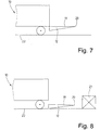
- a pivot position namely a pivot angle, is determined, which occupies the loading platform 12 by manually in the in the Fig. 1 . 2 and 7 shown, driven approximately horizontal pivot position in which the loading platform 12 can be loaded from the vehicle 10 with an object 21 or the object 21 is transported from the loading platform 12 in the structure of the vehicle 10.
- a first method provides for a plurality of measured values to be recorded successively in time by a measuring transmitter, for example the at least one angle transmitter 18 and to determine a particular position of the loading platform. This is done for the purpose of eliminating vibrations of the angle sensor 18 or other transducer of the tail lift 11. Thus, with not quite decayed oscillations of the angle sensor 18 or of another measuring transmitter, it is possible to reliably determine exact positions, in particular the angle corresponding to the pivoting position of the loading platform 12.
- the determination of the measured values takes place when the loading platform 12 is not actuated, ie when it is neither raised, lowered nor pivoted.
- the loading platform 12 is then practically silent. If the loading platform 12 is stopped, for example, after pivoting, it comes to a low springs of the loading platform 12, which also the suspension of the vehicle 10 may be involved.
- the at least one angle sensor 18, in particular a movable part required for angle measurements thereof exerts vibrations for a certain time.
- a short time for example 1 to 5 seconds after stopping the pivoting of the loading platform 12 during the oscillation of the angle sensor 18, several measured values are recorded successively in time by the angle sensor 18.
- the angle values can be recorded in direct temporal succession, ie without a pause between successive measured values, but also with time intervals, ie pauses between the determination of the respective measured value.
- the duration of the measurement can be up to 20 seconds in total.
- the measurement takes place in a time window of 2 to 5 seconds, in particular about 3 seconds. During this time, a larger number of measured values can be recorded, whereby the number of measured values can be arbitrary.
- the vibrations of the moving part of the angle sensor 18 more and more, but preferably not quite decayed.
- the successive measured values are recorded at different oscillation states, in particular amplitudes, of the moving part of the respective angle sensor 18.
- an average value can be formed, which actually corresponds to or approaches the angle value of the loading platform 12 to be detected, because the oscillations of the moving one result from the averaging of several successive measurements with decreasing vibrations Part of the respective angle sensor 18 can be eliminated and thereby not distort the measured angle.
- the method described above is used for the method described below in more detail for automatically starting manually adjusted swivel angle of the loading platform 12.
- the loading platform 12 is first swung down manually behind the vehicle body by the operator by means of the operating part 17 in a swivel position in which the useful surface 19 of the loading platform 12 is horizontal or at least approximately horizontally aligned and is located behind the bed of the vehicle 10.
- the at least one angle sensor 18 determines a swivel angle associated with the swivel position. The swivel angle is then, when it is based on the effective area 19 of the loading platform 12, with horizontally oriented loading platform 12 zero degrees.
- Such a horizontal pivoting angle of the useful surface 19 of the loading platform 12 is in the Fig.
- the swivel angle can also be slightly greater than zero degrees, so that the useful surface 19 to the top 20 of the loading platform 12 increases slightly.
- a pivoting position or such a swivel angle is approached manually, so that the article 21, especially if he is on a trolley, does not herunterner from the loading platform 12 or slide down and because by the weight of the article 21, the loading platform loaded with it 12 by elastic deformation or deflection of the vehicle 10 changes its angle to the effect that the tip 20 drops below the weight of the article 21.
- This sinking is in the Fig. 3 indicated by the dashed lines indicated loading platform 12, while the manually driven pivot angle of the unloaded loading platform 12 is shown in phantom in this figure.
- the manually pivoted to the beginning of the loading or unloading pivot position namely the associated pivot angle
- the tilt angle of the unloaded loading platform is the angle encoder 18 both when loading the loading platform 12 from the back of the vehicle 10, which is due to the Fig. 2 to 6 is clarified, determined as well as when loading the loading platform 12 from the ground 22 in accordance with the Fig. 7 to 11 ,
- the loading platform 12 is loaded from the vehicle with the article 21 passes from the manual setting of the pivot position of the pivot angle of the loading platform 12 to the loading of the loading platform 12 with the object 21 some time. During this time, there is no actuation of the tail lift, so that the loading platform 12 is not pivoted and not lowered. This time can be used by the angle sensor 18 at still in the initial pivot position befind Anlagen empty, so unloaded, loading platform 12 to determine the true unadulterated, despite the changing in the measurement by vibrations of the moving part of the angle sensor 18 positions this Moving part of the angle sensor 18.
- the article 21 After the measurement of the pivoting angle of the loading platform 12 is completed, which happens at a time when the article 21 can not yet be applied to the loading platform 12, the article 21 reaches the useful surface 19 of the loading platform 12 Loading platform 12 by the inclination of the loading platform 12 changes. This happens according to the Fig. 3 such that the tip 20 of the loaded loading platform 12 is opposite the top 20 of the unloaded loading platform 12 (dashed in the Fig. 3 shown) lowers. In the embodiment shown here, the useful surface 19 of the loading platform 12 extends slightly inclined to the top 20.
- such a pivot position can be approached manually, in which the useful surface 19 slightly increases to the top 20, so that after loading the loading platform 12, the useful surface 19 does not drop so sharply towards the tip 20 or, ideally, the useful surface 19 extends horizontally.
- the loading platform 12 After loading, the loading platform 12 is lowered to the ground 22. Due to the wedge shape of the loading platform 12, only the underside of a vehicle 10 pointing transverse edge of the loading platform 12 reaches the bottom 22. Here, the top 20 of the loading platform 12 is still spaced from the bottom 22, which does not allow the object 21 of the To move down loading platform 12 ( Fig. 4 ). For this reason, a so-called ground equalization or even edge edge adjustment by the loading platform 12 is pivoted until the tip 20 rests on the floor 22 ( Fig. 5 ). The useful surface 19 of the loading platform 12 is now substantially transitionless to the bottom 22 via to shut down the object 21 of the loading platform 12th
- the loading platform 12 After the loading platform 12 is empty, it is automatically returned by the control for reversing the Bodenan Dermatung, namely until reaching the angle of the encoder 18 at unloaded loading platform 12, initially once manually approached tilt angle of the loading platform 12 (FIG. Fig. 6 ). Subsequently, the empty loading platform 12 is raised, after which they are the starting position of the Fig. 2 has reached again and the tilt angle of the loading platform is the same as in the Fig. 2 namely, corresponds to the pivot angle of the empty loading platform 12, which is manually approached at the beginning of the unloading process of the vehicle 10.
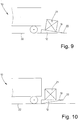
- the Fig. 7 to 11 show the case where the vehicle 10 is loaded with the article 21.
- the loading platform 12 is lowered immediately after swinging up and the manual start of the swivel position or the swivel angle.
- the empty loading platform 12 immediately from in the Fig. 7 lowered starting position shown with the manually approached swivel angle to the bottom 22.
- the tip 20 of the loading platform 12 is then still at a distance above the ground 22 (FIG. Fig.
- the angle transmitter 18 only needs to determine a single angular value corresponding to the pivoting angle of the loading platform 12. This can be done very quickly, so that after lowering the loading platform 12 to the ground 22 immediately the ground leveling of the loading platform 12 can take place, the tip 20 reaches the bottom 22.
- the loading platform 12 is loaded with the object 21 ( Fig. 9 ). Thereafter, the soil equalization is automatically reversed by the controller automatically re-starts the previously stored tilt angle of the empty loading platform 12, with the object 21 (FIG. Fig. 10 ). The weight of the article 21 thereby does not affect the swing angle of the loading platform 12. This is also brought under the load of the article 21 caused suspensions or deformations of the tail lift 11 with the loading platform 12 in the initially manually set pivot position of the empty loading platform 12. By subsequently lifting the loading platform 12, the object 21 is brought to the level of the loading area of the vehicle 10 ( Fig. 11 ). In this case, the swivel angle of the loading platform 12 corresponds to that which was approached manually by the operator after opening the loading platform 12 at the beginning of the loading operation of the vehicle 10 ( Fig. 7 ).
- the respective angle sensor 18 always determines the manually approached at the beginning of the loading or unloading swing angle of the loading platform 12 with unloaded loading platform 12, either at not yet lowered loading platform ( Fig. 2 ) or with lowered loading platform 12 (FIG. Fig. 8 ) before the soil leveling. In both cases, the manually approaching swivel angle is determined when the loading platform 12 is empty. The decision as to whether the manually approached tilt angle of the loading platform 12 before lowering (FIG. Fig. 2 ) or after lowering ( Fig. 8 ) is determined, then how long the loading platform 12 remains in the pivot position before it is lowered.
- this time exceeds a predetermined period of time, for example 5 to 20 seconds, preferably 10 seconds, this indicates that the loading platform 12 is to be loaded from the vehicle 10, because such loading takes some time and therefore does not immediately relieve the loading platform is lowered to reach the pivot position. If, however, immediately after the manual pivoting of the loading platform in the pivoting position also lowering the loading platform 12 takes place, this indicates a loading of the loading platform 12 at the bottom 22 out. Then the swivel angle of the angle sensor 18 can be determined when resting on the ground loading platform 12 before the ground leveling become.
- a predetermined period of time for example 5 to 20 seconds, preferably 10 seconds
Abstract
Description
Die Erfindung betrifft ein Verfahren zum Steuern einer eine Ladeplattform aufweisenden Hubladebühne gemäß dem Oberbegriff des Anspruchs 1 bzw. 7.The invention relates to a method for controlling a loading platform having a tail lift according to the preamble of claim 1 and 7, respectively.
Hubladebühnen dienen dazu, das Be- und Entladen von Fahrzeugen mit insbesondere schweren Gegenständen zu erleichtern. Dazu verfügen die Hubladebühnen über eine vorzugsweise an der Rückseite eines Fahrzeugaufbaus schwenk-, heb- und senkbar angelenkte Ladeplattform.Tail lifts serve to facilitate the loading and unloading of vehicles, especially heavy objects. For this purpose, the tail lifts have a preferably hinged at the rear of a vehicle body, raised and lowered hinged loading platform.
Zum Be- und Entladen wird die in einer Ruhestellung hinter dem Fahrzeugaufbau hochgeschwenkte Ladeplattform heruntergeschwenkt in eine horizontale oder nahezu horizontale Schwenkposition. Durch Absenken der so heruntergeklappten Ladeplattform können die zu entladenden Gegenstände vom Niveau des Fahrzeugaufbaus auf ein niedriges Niveau, insbesondere ein Bodenniveau, gebracht werden. Umgekehrt wird die Ladeplattform zum Beladen des Fahrzeugs angehoben.For loading and unloading in a rest position behind the vehicle body swung up loading platform is pivoted down into a horizontal or almost horizontal pivot position. By lowering the loading platform folded down in this manner, the objects to be unloaded can be brought from the level of the vehicle bodywork to a low level, in particular a ground level. Conversely, the loading platform is lifted to load the vehicle.
Die Ladeplattform ist von der Seite gesehen keilförmig ausgebildet mit einer in Fahrtrichtung des Fahrzeugs gesehen hinteren Spitze. Die Spitze ist gebildet durch eine freie, hintere Querkante der Ladeplattform. Infolge der Keilform muss die Ladeplattform nach dem Absenken auf den Boden erneut verschwenkt werden, damit ihre Spitze im Wesentlichen übergangslos am Boden anliegt. Im Fachjargon spricht man hierbei von einer Bodenangleichung. Vor dem erneuten Hochfahren muss die Bodenangleichung der Ladeplattform wieder rückgängig gemacht werden durch ein Zurückschwenken, damit die Spitze vom Boden abgehoben wird und die obere Nutzfläche der Plattform wieder eine horizontale oder nahezu horizontale Schwenkposition einnimmt. Das ist zeitaufwendig und erfordert vom Bediener viel Geschick und Erfahrung.The loading platform is seen from the side wedge-shaped with a seen in the direction of travel of the vehicle rear peak. The top is formed by a free, rear transverse edge of the loading platform. As a result of the wedge shape, the loading platform must be pivoted again after lowering to the ground, so that their tip is substantially seamless on the ground. In technical jargon one speaks of it a soil approximation. Before rebooting, the floor leveling of the loading platform must be reversed by pivoting back so that the top is lifted off the ground and the platform upper surface returns to a horizontal or near horizontal pivot position. This is time consuming and requires a lot of skill and experience from the operator.
Es sind bereits Hubladebühnen bekannt, bei denen die Bodenangleichung durch eine entsprechende Steuerung automatisch rückgängig gemacht wird. Dazu ist die Hubladebühne, insbesondere die Ladeplattform, mit mindestens einem entsprechenden Sensor, zum Beispiel einem Messwert- oder Winkelgeber, versehen. Problematisch ist hierbei jedoch, dass die Ladeplattform beim Beladen mit insbesondere schweren Gegenständen ihre anfangs manuell eingestellte und in der Steuerung abgespeicherte Schwenkposition verändert, sich nämlich die Spitze absenkt. Das führt zu unterschiedlichen Schwenkpositionen, wodurch nicht die ursprüngliche Schwenkposition automatisch wieder angefahren wird.There are already tail lifts known in which the soil equalization is automatically reversed by an appropriate control. For this purpose, the tail lift, in particular the loading platform, with at least one corresponding sensor, for example, a measured value or angle encoder, provided. The problem here is, however, that the loading platform when loading with particular heavy objects their initially set manually and stored in the control pivot position changes, namely, the tip lowers. This leads to different pivot positions, whereby not the original pivot position is automatically approached again.
Bei bekannten Hubladebühnen, die eine bestimmte Schwenkposition automatisch wieder anfahren, tritt noch ein weiteres Problem dadurch auf, dass die Sensoren, insbesondere Neigungssensoren oder Winkelgeber, eine vom Stoppen des Schwenkvorgangs, insbesondere die dabei federnde Ladeplattform, in Schwingungen versetzt werden. Diese Schwingungen verfälschen den von den Sensoren und vor allem Winkelgebern ermittelten Messwert. Die Folge ist, dass die Steuerung beispielsweise beim automatischen Anfahren der voreingestellten Schwenkposition eine falsche Schwenkposition, insbesondere einen falschen Schwenkwinkel, anfährt.In the case of known tail lifts which automatically approach a specific swivel position, a further problem arises in that the sensors, in particular inclination sensors or angle transmitters, are set in motion by stopping the swiveling process, in particular by the resilient loading platform. These vibrations distort the measured value determined by the sensors and, in particular, angle encoders. The result is that the controller, for example, the automatic starting of the preset pivot position, a wrong pivot position, in particular a wrong swing angle, anfährt.
Ausgehend vom Vorstehenden liegt der Erfindung die Aufgabe zugrunde, ein Verfahren zum Steuern einer Hubladebühne zu schaffen, das eine vorgegebene Schwenkposition, insbesondere einen vorgegebenen Schwenkwinkel, der Ladeplattform mit großer Genauigkeit selbsttätig wieder anfährt.Based on the above, the present invention seeks to provide a method for controlling a tail lift, which automatically restarts a predetermined pivot position, in particular a predetermined pivot angle, the loading platform with great accuracy again.
Ein Verfahren zur Lösung dieser Aufgabe weist die Maßnahmen des Anspruchs 1 auf. Demnach ist es vorgesehen, die manuell angefahrene Schwenkposition, insbesondere den manuell angefahrenen Schwenkwinkel, der unbeladenen Ladeplattform zu ermitteln. Es wird nach diesem Verfahren die Schwenkposition ermittelt, bevor sie vom Gewicht eines oder mehrerer Gegenstände, womit die Ladeplattform beladen worden ist, verfälscht wird durch eine vom Gewicht der Ladung der Ladeplattform herbeigeführte Einfederung derselben und die sich dadurch verändernde Schwenkposition, insbesondere eine Veränderung des Schwenkwinkels. Wenn nach dem Entladen der auf den Boden abgesenkten Ladeplattform die dazu durchgeführte Bodenangleichung durch das automatische Zurückschwenken wieder rückgängig gemacht wird, erfolgt insbesondere bei leerer Ladeplattform ein genaues Anfahren der vorher manuell angefahrenen und in einer Steuerung abgespeicherten Schwenkposition bzw. des Schwenkwinkels der Ladeplattform. Dadurch ist es nicht erforderlich, bei sich ändernder Beladung oder unbeladener Ladeplattform die automatisch wieder angefahrene Schwenkposition, insbesondere den automatisch angefahrenen Schwenkwinkel, manuell zu korrigieren.A method for achieving this object comprises the measures of claim 1. Accordingly, it is provided to determine the manually approached pivot position, in particular the manually approached pivot angle, the unloaded loading platform. It is determined by this method, the pivot position before it is falsified by the weight of one or more objects, with which the loading platform has been loaded by a caused by the weight of the load platform loading of the same and the thereby changing pivot position, in particular a change in the swivel angle. If, after unloading the platform lowered to the ground, the floor adaptation performed by the automatic pivoting back is canceled again, especially when the loading platform is empty, an accurate approach of the previously manually approached and stored in a control pivot position or the swivel angle of the loading platform. As a result, it is not necessary to manually correct the automatically restarted pivot position, in particular the automatically approached pivot angle, when the loading or the loading platform is changing.
Vorzugsweise ist das Verfahren so ausgebildet, dass die Schwenkposition oder der Schwenkwinkel vor dem Absenken der Ladeplattform ermittelt wird, wenn die Ladeplattform beladen abgesenkt wird, wohingegen die Schwenkposition erst nach dem Absenken der Ladeplattform ermittelt wird, wenn diese unbeladen abgesenkt wird. Bei dieser Vorgehensweise steht genügend Zeit zur exakten Ermittlung der Schwenkposition bzw. Schwenkwinkels der Ladeplattform zur Verfügung, wenn diese im noch nicht abgesenkten Zustand vom Fahrzeug aus beladen wird. Das Ermitteln des exakten Schwenkwinkels verzögert dadurch die Beladung der Ladeplattform vom Fahrzeug aus nicht. Wenn hingegen die Ladeplattform unbeladen abgesenkt wird, steht nicht genügend Zeit zur Ermittlung oder Abspeicherung der exakten Schwenkposition oder des exakten Schwenkwinkels zur Verfügung. Dann erfolgt die Ermittlung der Schwenkposition oder des Schwenkwinkels erst nach dem Absenken der Ladeplattform auf den Boden, aber vor dem anschließenden Verschwenken der Ladeplattform zur Herbeiführung der Bodenangleichung. Wenn die Ladeplattform im leeren Zustand auf den Boden abgesenkt ist, kann die Schwenkposition, insbesondere der Schwenkwinkel, sehr rasch ermittelt werden, weil infolge des Aufliegens mindestens eines Teils der Ladeplattform auf den Boden die Sensoren, insbesondere Winkelsensoren oder Winkelgeber, nicht schwingen und der Messwert mit einer Messung sogleich zuverlässig ermittelbar ist. Die Ermittlung der Schwenkposition bzw. des Schwenkwinkels der auf den Boden abgesenkten Ladeplattform lässt bei leerer Plattform eine sofortige Bodenangleichung zu, ohne dass gewartet werden muss, bis eine exakte Schwenkposition bzw. ein exakter Schwenkwinkel ermittelbar ist.Preferably, the method is designed such that the pivot position or the swivel angle is determined prior to lowering the loading platform when the loading platform is lowered laden, whereas the pivot position is determined only after lowering the loading platform when it is lowered unloaded. In this procedure, there is sufficient time for the exact determination of the pivot position or swivel angle of the loading platform available when it is loaded in the not yet lowered state from the vehicle. The determination of the exact swing angle thereby does not delay the loading of the loading platform from the vehicle. If, however, the loading platform is lowered unloaded, there is not enough time to determine or store the exact pivot position or the exact swing angle available. Then, the determination of the pivot position or the swivel angle takes place only after the lowering of the loading platform to the ground, but before the subsequent pivoting of the loading platform to bring about the ground leveling. When the loading platform is lowered to the ground in the empty state, the pivoting position, in particular the pivoting angle, can be determined very quickly, because due to the resting of at least a portion of the loading platform on the ground, the sensors, in particular angle sensors or angle encoders, do not oscillate and the measured value with a measurement immediately reliably determined. The determination of the swivel position or the swivel angle of the lowered to the ground loading platform allows for an empty platform an immediate ground leveling, without having to wait until an exact pivot position or an exact swivel angle can be determined.
Eine weitere bevorzugte Ausgestaltung des Verfahrens sieht es vor, dass dann, wenn nach dem Erreichen der Schwenkposition die Ladeplattform innerhalb einer bestimmten Zeitspanne abgesenkt wird, die Schwenkposition bzw. der Schwenkwinkel bei auf den Boden abgesenkter Ladeplattform ermittelt wird. Auf diese Weise erhält die Steuerung Informationen darüber, ob sie den Schwenkwinkel vor dem Absenken der Ladeplattform oder nach dem Absenken der Ladeplattform bis auf den Boden ermitteln kann. Die Wahl der jeweils vorzunehmenden, unterschiedlichen Ermittlungsweisen der Schwenkposition oder Schwenkwinkels kann somit ohne nennenswerten zusätzlichen Aufwand erfolgen, vor allem allein durch die Steuerung.A further preferred embodiment of the method provides that when the loading platform is lowered within a certain period of time after reaching the swivel position, the swivel position or the swivel angle is determined with the platform lowered to the floor. In this way, the controller receives information about whether it is the swivel angle before lowering the loading platform or after lowering the loading platform to the ground can determine. The choice of each to be made, different ways of determining the pivot position or swivel angle can thus be done without significant additional effort, especially only by the controller.
Eine andere vorteilhafte Ausgestaltung des Verfahrens sieht es vor, dass dann, wenn die Ladeplattform in der Schwenkposition eine bestimmte Zeitspanne von vorzugsweise 5 bis 15 Sekunden verbleibt, also in dieser Zeitspanne nicht abgesenkt wird, die Schwenkposition vor dem Absenken der Ladeplattform ermittelt wird. Diese Vorgehensweise geht von der Erkenntnis aus, dass das Beladen der Ladeplattform vom Fahrzeug eine längere Zeit in Anspruch nimmt, die in jedem Fall größer ist als 15 Sekunden. Dann verbleibt die Ladeplattform während ihrer Beladung in der horizontalen oder nahezu horizontalen Schwenkposition. Stellt ein Zeitglied dieses fest, wird die Zeit, bis der Gegenstand auf die Ladeplattform geladen ist, genutzt, um vom Messwertgeber, insbesondere Winkelgeber, die Schwenkposition, insbesondere den Schwenkwinkel der unbeladenen Ladeplattform, zu ermitteln. Vorzugsweise wird nach dem Anfahren der Schwenkposition der Ladeplattform etwas gewartet, bis die Messung der Schwenkposition bzw. des Schwenkwinkels der Ladeplattform beginnt, und zwar vorzugsweise bis zu 5 Sekunden. Dann werden bevorzugt mehrere zeitlich aufeinanderfolgende Messungen durchgeführt, wobei während dieser Messungen Schwingungen des Messwertgebers oder Winkelaufnehmers mehr und mehr abklingen. Es kann so durch Mittelwertbildung, Interpolation oder andere statistische Rechenoperationen die Schwenkposition bzw. der Schwenkwinkel ermittelt werden, der auch vor dem vollständigen Abklingen der Schwingungen dem exakten oder nahezu exakten Wert der Schwenkposition oder des Schwenkwinkels entspricht.Another advantageous embodiment of the method provides that when the loading platform in the pivot position for a certain period of preferably 5 to 15 seconds remains, that is not lowered in this period, the pivot position is determined before lowering the loading platform. This approach is based on the recognition that loading the loading platform from the vehicle takes a longer time, which is always greater than 15 seconds. Then the loading platform remains in the horizontal or near horizontal pivot position during its loading. If a timer detects this, the time until the object is loaded onto the loading platform is used to determine the swivel position, in particular the swivel angle of the unloaded loading platform, by the transmitter, in particular the angle transmitter. Preferably, after the starting of the pivoting position of the loading platform, a slight wait is made until the measurement of the pivoting position or of the pivoting angle of the loading platform begins, preferably up to 5 seconds. Then, a plurality of temporally successive measurements are preferably carried out, during which measurements oscillations of the transmitter or angle sensor decay more and more. It can be determined by averaging, interpolation or other statistical arithmetic operations, the pivot position or the swivel angle, which also corresponds to the exact or nearly exact value of the pivot position or the swivel angle before the complete decay of the vibrations.
Gemäß einer bevorzugten Ausgestaltung des Verfahrens wird die ermittelte und in der Steuerung abgespeicherte Schwenkposition oder der Schwenkwinkel bei der Rückgängigmachung der Bodenangleichung und vor dem Anheben der Beladeplattform vom Boden durch die Steuerung automatisch wieder angefahren. Es wird dabei diejenige Schwenkposition oder derjenige Schwenkwinkel angefahren, der der unbeladenen Ladeplattform entspricht. Wenn die Ladeplattform demnach, was beim Entladen eines Fahrzeugs üblich ist, unbeladen wieder hochgefahren wird, nimmt nach dem Hochfahren die Ladeplattform wieder den manuell eingestellten Schwenkwinkel oder die Schwenkposition der unbeladenen Ladeplattform ein.According to a preferred embodiment of the method, the determined and stored in the control pivot position or the swivel angle in the reversal of the ground equalization and before lifting the loading platform from the ground by the controller automatically restarted. It is approached that pivot position or that pivot angle, which corresponds to the unloaded loading platform. Accordingly, if the loading platform, which is customary when unloading a vehicle, is raised again unloaded, after loading the loading platform again assumes the manually set swivel angle or the swivel position of the unloaded loading platform.
Die Erfindung sieht es bevorzugt vor, den Schwenkwinkel der zum Beladen in eine horizontale oder nahezu horizontale Position aufgeschwenkten leeren Ladeplattform von mindestens einem Winkelgeber oder Winkelsensor zu ermitteln. Es handelt sich dabei um den manuell von der Bedienungsperson zu Anfang des Be- oder Entladevorgangs des Fahrzeugs angefahrenen Schwenkwinkel der unbeladenen Ladeplattform.The invention preferably provides for the swivel angle of the empty loading platform, which is swiveled open for loading into a horizontal or almost horizontal position to determine at least one angle encoder or angle sensor. It is the manually swept by the operator at the beginning of loading or unloading the vehicle tilt angle of the unloaded loading platform.
Ein weiteres Verfahren zur Lösung der eingangs genannten Aufgabe, wobei es sich auch um eine bevorzugte Weiterbildung einzelner oder aller Ausgestaltungen des zuvor beschriebenen Verfahrens handeln kann, weist die Maßnahmen des Anspruchs 7 auf. Dieses Verfahren sieht es vor, dass mehrere von einem Messwertgeber zeitlich nacheinander ermittelte Messwerte zum Ermitteln einer Position oder eines Winkels, vorzugsweise der Schwenkposition bzw. des Schwenkwinkels der Ladeplattform, herangezogen werden. Diese Vorgehensweise geht von der Erkenntnis aus, dass beim Herunterschwenken der Ladeplattform in die zum Beladen oder Entladen geeignete horizontale oder nahezu horizontale Schwenkposition von Bewegungen der Ladeplattform der jeweilige Messwertgeber in Schwingungen versetzt wird, die nur relativ langsam abklingen. Ein einzelner erfasster Messwert würde dadurch verfälscht. Indem erfindungsgemäß in zeitlicher Aufeinanderfolge mehrere Messwerte ermittelt werden, können daraus die exakte Schwenkposition, insbesondere der exakte Schwenkwinkel, rechnerisch ermittelt werden. Diese Ermittlung kann nach verschiedenen mathematischen Methoden erfolgen, stets mit dem Ziel, die verschiedenen Schwingungszustände, insbesondere mehr und mehr abgeklungenen Schwingungen, des mindestens einen Messwertgebers bei der Messung zu berücksichtigen und zur Ermittlung des exakten Schwenkwinkels oder der exakten Schwenkposition zu eliminieren. Auch wenn die Schwingungen noch nicht ganz abgeklungen sind, lässt sich insbesondere der Schwenkwinkel so genau ermitteln und in der Steuerung abspeichern zur nachfolgenden automatischen Steuerung der Ladeplattform.Another method for the solution of the above-mentioned object, which may also be a preferred development of individual or all embodiments of the method described above, comprises the measures of claim 7. This method provides that a plurality of measured values ascertained chronologically one after the other by a transmitter are used to determine a position or an angle, preferably the pivoting position or the swivel angle of the loading platform. This approach is based on the knowledge that when swiveling down the loading platform in the suitable for loading or unloading horizontal or nearly horizontal pivot position of movements of the loading platform of the respective transmitter is vibrated, which decay relatively slowly. A single measured value recorded would thereby be corrupted. By determining a plurality of measured values in temporal succession according to the invention, the exact pivoting position, in particular the exact pivoting angle, can be calculated therefrom. This determination can be made according to various mathematical methods, always with the aim of taking into account the different vibration states, in particular more and more decayed vibrations, of the at least one transmitter during the measurement and to eliminate them to determine the exact swing angle or exact swing position. Even if the vibrations have not quite subsided, in particular the swivel angle can be determined so accurately and stored in the controller for subsequent automatic control of the loading platform.
Eine vorteilhafte Weiterbildung des zuvor beschriebenen Verfahrens sieht es vor, die zeitlich aufeinanderfolgenden Messwerte von mindestens einem Messwertgeber zu ermitteln, während die Ladeplattform weder verschwenkt noch angehoben oder abgesenkt wird. Die Ermittlung des Messwerts erfolgt so bei momentan unbetätigter Ladeplattform. Vorzugsweise ist weiterhin vorgesehen, die zeitlich aufeinanderfolgenden Messwerte von dem mindestens einen Messwertgeber nach dem manuellen Verschwenken der Ladeplattform in eine horizontale oder nahezu horizontale Position bei noch unbeladener Ladeplattform aufzunehmen.An advantageous development of the method described above provides for the temporally successive measured values to be determined by at least one measuring transmitter, while the loading platform is neither pivoted nor raised or lowered. The determination of the measured value takes place in such a way at currently unattended loading platform. Preferably, it is further provided to record the temporally successive measured values from the at least one sensor after the manual pivoting of the loading platform into a horizontal or almost horizontal position with the loading platform still unloaded.
Bevorzugt ist das Verfahren so weitergebildet, dass die Schwenkposition manuell angefahren wird. Beim Erreichen der gewünschten Schwenkposition oder des gewünschten Schwenkwinkels wird eine Zeit lang gewartet und danach vom Messwertgeber innerhalb einer bestimmten Zeitspanne mehrmals nacheinander in direkter Aufeinanderfolge oder mit zeitlichen Abständen Messwerte aufgenommen und hieraus rechnerisch mindestens annähernd die Schwenkposition bzw. der Schwenkwinkel errechnet. Dieser errechnete Schwenkwinkel oder die Schwenkposition werden dann in der Steuerung abgespeichert und später vorzugsweise wiederholt von der Steuerung angefahren. Insbesondere erfolgen die geschilderten Vorgänge bei noch unbeladener Ladeplattform. Die Verfahrensweise eliminiert Ungenauigkeiten bei der Ermittlung der Schwenkposition bzw. des Schwenkwinkels, die durch beim Stoppen des Schwenkvorgangs der Ladeplattform hervorgerufene Schwingungen mindestens des jeweiligen Messwertgebers, insbesondere Winkelwertgebers, entstehen. Trotz dieser Schwingungen ermöglicht das erfindungsgemäße Verfahren die Ermittlung und Abspeicherung eines exakten oder zumindest nahezu exakten Schwenkwinkels der Ladeplattform. Die Messung erfolgt während des Abklingens der Schwingungen des mindestens einen Messwertaufnehmers, wobei die Messungen abgeschlossen sein können, bevor die Schwingungen vollständig abgeklungen sind, weil durch die zeitlich aufeinanderfolgenden wiederholten Messungen das Abklingverhalten der Schwingungen des mindestens einen Messwertaufnehmers insbesondere tendenziell berücksichtigt wird und so rechnerisch die Schwenkposition bzw. der Schwenkwinkel ohne Verfälschung der beim Messen noch nicht abgeklungenen Schwingungen des Messwertaufgebers, insbesondere Winkelwertgebers, ermittelbar sind.Preferably, the method is developed so that the pivot position is approached manually. When reaching the desired pivot position or the desired pivoting angle is maintained for a while and then recorded by the transmitter within a certain period of time several times in succession in direct succession or at intervals measured values and calculated from this mathematically at least approximately the pivot position and the pivot angle. This calculated pivot angle or the pivot position are then stored in the controller and later preferably approached repeatedly by the controller. In particular, the described processes take place with the loading platform still empty. The procedure eliminates inaccuracies in the determination of the pivot position or the swivel angle caused by the oscillation of the loading platform caused vibrations of at least the respective sensor, in particular angle encoder, caused. Despite these oscillations, the method according to the invention makes it possible to ascertain and store an exact or at least almost exact pivoting angle of the loading platform. The measurement takes place during the decay of the oscillations of the at least one transducer, wherein the measurements can be completed before the vibrations have completely decayed because the decay behavior of the vibrations of the at least one transducer is tended to be taken into account in particular by the successive repeated measurements Swivel position or the swivel angle without falsification of the not yet subsided during measurement oscillations of the Meßwertaufgebers, in particular angle sensor, can be determined.
Vorzugsweise wird als Messwertgeber ein Winkelgeber oder ein vergleichbarer den Schwenkwinkel der Ladeplattform ermittelnder Messwertgeber bzw. Sensor verwendet, so dass Winkelwerte der Schwenkposition der Ladeplattform ermittelbar sind. Vorzugsweise wird bei unbetätigter und unbeladener Ladeplattform anhand der vom Winkelgeber oder einem sonstigen Sensor ermittelten Winkelwerte, insbesondere Schwenkwinkelwerte, durch Mittelwertbildung der manuell angefahrene Schwenkwinkel der Ladeplattform genau ermittelt, wobei durch das erfindungsgemäße Verfahren Schwingungen des Winkelgebers oder eines sonstigen Messwertgebers ganz oder zumindest größtenteils eliminiert werden.Preferably, an angle transmitter or a comparable transmitter or sensor determining the swivel angle of the loading platform is used as the transmitter, so that angle values of the swivel position of the loading platform can be determined. Preferably, when the loading platform is uncontrolled and unloaded, the angle of rotation of the loading platform determined manually by averaging is determined precisely by averaging, whereby vibrations of the angle sensor or of another measuring transmitter are completely or at least largely eliminated by the method according to the invention ,
Ein bevorzugtes Ausführungsbeispiel der Erfindung wird nachfolgend anhand der Zeichnung näher erläutert. In dieser zeigen:
- Fig. 1
- eine Seitenansicht eines hinteren Teils eines Fahrzeugs mit einer Hubladebühne bei in eine Schwenkposition herunterschwenkter Ladeplattform,
- Fig. 2
- eine schematische Seitenansicht gemäß der
Fig. 1 bei manuell in die Schwenkposition heruntergeschwenkter unbeladener Ladeplattform, - Fig. 3
- eine Darstellung analog zur
Fig. 2 bei vom Fahrzeug aus beladener Ladeplattform, - Fig. 4
- eine Darstellung analog zur
Fig. 2 bei beladener und auf den Boden abgesenkter Ladeplattform, - Fig. 5
- eine Darstellung analog zur
Fig. 2 bei einer beladenen Ladeplattform nach der Bodenangleichung, - Fig. 6
- eine Darstellung analog zur
Fig. 2 mit entladener Ladeplattform und rückgängig gemachter Bodenangleichung, - Fig.7
- eine schematische Seitenansicht einer manuell in eine Schwenkposition gefahrener Ladeplattform,
- Fig. 8
- eine Darstellung analog zur
Fig. 7 bei auf den Boden abgesenkter leerer Ladeplattform vor der Bodenangleichung, - Fig. 9
- eine Darstellung analog zur
Fig. 7 mit der vollständig nach der Bodenangleichung auf dem Boden anliegender Ladeplattform nach dem Beladen, - Fig. 10
- eine Darstellung analog zur
Fig. 7 mit der beladenen Ladeplattform nach der automatischen Rückgängigmachung der Bodenangleichung, und - Fig. 11
- eine Darstellung analog zur
Fig. 7 mit in die ursprüngliche Schwenkposition zurückgekehrter, hochgefahrener Ladeplattform vor dem Entladen.
- Fig. 1
- a side view of a rear part of a vehicle with a tail lift when swung down in a pivoting loading platform,
- Fig. 2
- a schematic side view according to the
Fig. 1 with the unloaded loading platform swung down manually into the swivel position, - Fig. 3
- a representation analogous to
Fig. 2 in the case of a loading platform loaded from the vehicle, - Fig. 4
- a representation analogous to
Fig. 2 loaded loading platform lowered to the ground, - Fig. 5
- a representation analogous to
Fig. 2 on a loaded loading platform after ground leveling, - Fig. 6
- a representation analogous to
Fig. 2 with unloaded loading platform and undone ground leveling, - Figure 7
- a schematic side view of a manually driven in a pivoting position loading platform,
- Fig. 8
- a representation analogous to
Fig. 7 with empty loading platform lowered to the ground before ground leveling, - Fig. 9
- a representation analogous to
Fig. 7 with the loading platform resting completely on the ground after ground leveling after loading, - Fig. 10
- a representation analogous to
Fig. 7 with the loaded loading platform after the automatic resetting of the ground leveling, and - Fig. 11
- a representation analogous to
Fig. 7 with the platform raised to its original pivoting position before unloading.
Die Figuren zeigen eine an der Rückseite des Aufbaus eines teilweise dargestellten Fahrzeugs 10 montierte Hubladebühne 11. Die Hubladebühne 11 verfügt über eine ebene Ladeplattform 12 und ein Hubwerk 13. Das Hubwerk 13 ist mit einer starren Traverse 14 am Rahmen des Fahrzeugs 10 verbunden. Das Hubwerk 13 ist nach dem Parallelogrammprinzip aufgebaut, besteht nämlich im gezeigten Ausführungsbeispiel aus zwei auf gegenüberliegenden Seiten des Hubwerks 13 angeordnete Parallelogrammlenkerpaare mit jeweils zwei Lenkarmen. Die Parallelogrammlenkerpaare sind durch Druckmittelzylinder 15, 16, vorzugsweise Hydraulikzylinder, bewegbar. Die Druckmittelzylinder 15 und 16 dienen einerseits zum Schwenken und andererseits zum Anheben und Absenken der Ladeplattform 12.The
Die Ladeplattform 12 weist in einer in den Figuren dargestellten Seitenansicht eine keilförmige Gestalt auf. Die Ladeplattform 12 verjüngt sich zu einer freien, quer zur Fahrtrichtung des Fahrzeugs 10 verlaufenden Querkante. Dadurch entsteht an der in Fahrtrichtung gesehen hinteren, freien Querkante der Ladeplattform 12 eine Spitze 20, die es ermöglicht, den Gegenstand 21 vom Boden 22 im Wesentlichen übergangslos zu be- oder entladen.The
An einer Seite des Fahrzeugs 10 ist in der Nähe der Hubladebühne 11 ein Bedienteil 17 vorgesehen, womit eine Bedienungsperson manuell die Hubladebühne 11 betätigen kann durch entsprechendes Verschwenken, Abheben und Absenken der Ladeplattform 12.On one side of the
Mindestens der Ladeplattform 12 ist wenigstens ein Messwertgeber oder Sensor zugeordnet, bei dem es sich vorzugsweise um einen Winkelgeber 18 handelt. Es können auch mehrere Winkelgeber 18 vorgesehen sein. Alternativ kann mindestens ein Winkelgeber am Hubwerk 13, beispielsweise den Lenkerarmen, vorgesehen sein. Gegebenenfalls kann es sich hierbei aber auch um zusätzliche Winkelgeber 18 handeln. Die Winkelgeber 18 sind bevorzugt als Mikrosensoren ausgebildet, die ein mit der jeweiligen Neigung der Ladeplattform 12 sich proportional änderndes elektrisches Signal abgeben. Das jeweilige Signal mindestens des Winkelgebers 18 wird an eine nicht gezeigte Steuerung übertragen, die aus den elektrischen Signalen einen Winkel der oberen Nutzfläche 19 zur Horizontalen ermittelt. Insbesondere wird eine Schwenkposition, und zwar ein Schwenkwinkel, ermittelt, den die Ladeplattform 12 einnimmt, indem sie manuell in die in den
Die erfindungsgemäßen Verfahren werden nachfolgend unter Bezugnahme auf die
Ein erstes Verfahren sieht es vor, von einem Messwertgeber, beispielsweise dem mindestens einen Winkelgeber 18, mehrere Messwerte zeitlich nacheinander aufzunehmen und zum Ermitteln einer bestimmten Position der Ladeplattform heranzuziehen. Das erfolgt zu dem Zweck, Schwingungen des Winkelgebers 18 oder sonstiger Messwertgeber der Hubladebühne 11 zu eliminieren. So lassen sich bei noch nicht ganz abgeklungenen Schwingungen des Winkelgebers 18 oder eines sonstigen Messwertgebers zuverlässig exakte Positionen, insbesondere der Schwenkposition der Ladeplattform 12 entsprechende Winkel, ermitteln.A first method provides for a plurality of measured values to be recorded successively in time by a measuring transmitter, for example the at least one
Die Ermittlung der Messwerte erfolgt bei nicht betätigter Ladeplattform 12, also wenn diese weder angehoben, abgesenkt noch verschwenkt wird. Die Ladeplattform 12 steht dann praktisch still. Wenn die Ladeplattform 12 beispielsweise nach dem Verschwenken gestoppt wird, kommt es zu einem geringen Federn der Ladeplattform 12, woran auch die Federung des Fahrzeugs 10 beteiligt sein kann. Die Folge ist, dass der mindestens eine Winkelgeber 18, vor allem ein zu Winkelmessungen erforderliches bewegbares Teil derselben, eine gewisse Zeitlang Schwingungen ausübt. Damit gleichwohl zuverlässige Winkelwerte ermittelbar sind, werden kurze Zeit, beispielsweise 1 bis 5 Sekunden nach dem Stoppen des Verschwenkens der Ladeplattform 12 noch während des Schwingens des Winkelgebers 18 mehrere Messwerte zeitlich nacheinander vom Winkelgeber 18 aufgenommen. Die Winkelwerte können in direkter zeitlicher Aufeinanderfolge, also ohne eine Pause zwischen aufeinanderfolgenden Messwerten, aufgenommen werden, aber auch mit zeitlichen Abständen, also Pausen zwischen der Ermittlung des jeweiligen Messwerts. Die Dauer der Messung kann insgesamt bis zu 20 Sekunden betragen. Vorzugsweise erfolgt die Messung in einem Zeitfenster von 2 bis 5 Sekunden, insbesondere etwa 3 Sekunden. In dieser Zeit kann eine größere Anzahl von Messwerten aufgenommen werden, wobei die Anzahl der Messwerte beliebig sein kann.The determination of the measured values takes place when the
Durch die zeitlich aufeinanderfolgende Aufnahme mehrerer Messwerte sind die Schwingungen des bewegten Teils des Winkelgebers 18 mehr und mehr, aber vorzugsweise noch nicht ganz abgeklungen. Außerdem werden die aufeinanderfolgenden Messwerte bei unterschiedlichen Schwingungszuständen, insbesondere Amplituden, des bewegten Teils des jeweiligen Winkelgebers 18 aufgenommen. Auf diese Weise kann durch eine Mittelwertbildung aller beim Messvorgang vom Winkelgeber 18 aufgenommenen Messwerte ein Durchschnittswert gebildet werden, der tatsächlich dem zu erfassenden Winkelwert der Ladeplattform 12 entspricht, oder nahekommt, weil durch die Mittelwertbildung aus mehreren nacheinander erfolgenden Messungen bei abnehmenden Schwingungen die Schwingungen des bewegten Teils des jeweiligen Winkelgebers 18 sich eliminieren lassen und dadurch den gemessenen Winkel nicht verfälschen.By the temporal successive recording of several measured values, the vibrations of the moving part of the
Alternativ ist es denkbar, aus den mehreren seitlich aufeinanderfolgenden Messwerten rechnerisch die Schwingungen zu analysieren und daraus iterativ bzw. empirisch den tatsächlichen Winkelwert zu ermitteln, der sich nach dem vollständigen Abklingen der Schwingungen einstellen würde.Alternatively, it is conceivable to mathematically analyze the oscillations from the plurality of laterally successive measured values and to use iteratively or empirically to determine the actual angle value that would ensue after the oscillations have completely decayed.
Der in vorstehend beschriebener Weise ermittelte exakte Wert des Winkels der Ladeplattform 12 kann von der Steuerung der Hubladebühne 11 zum automatischen Anfahren verschiedenster Positionen der Ladeplattform 12 eingesetzt werden.The determined in the manner described above exact value of the angle of the
Bevorzugt wird das vorstehend beschriebene Verfahren für das im Folgenden näher beschriebene Verfahren zum automatischen Anfahren manuell eingestellter Schwenkwinkel der Ladeplattform 12 eingesetzt.Preferably, the method described above is used for the method described below in more detail for automatically starting manually adjusted swivel angle of the
Zu Beginn des Be- oder Entladevorgangs des Fahrzeugs 10 wird zunächst manuell von einer Bedienungsperson mittels des Bedienteils 17 die Ladeplattform 12 von der während der Fahrt des Fahrzeugs 10 hochgeschwenkten Stellung hinter dem Fahrzeugaufbau heruntergeschwenkt in eine Schwenkposition, bei der die Nutzfläche 19 der Ladeplattform 12 horizontal oder zumindest etwa horizontal ausgerichtet ist und sich hinter der Ladefläche des Fahrzeugs 10 befindet. In dieser manuell angefahrenen Ausgangsposition, die hier als Schwenkposition bezeichnet wird, ermittelt der mindestens eine Winkelgeber 18 einen zur Schwenkposition gehörenden Schwenkwinkel. Der Schwenkwinkel beträgt dann, wenn er auf die Nutzfläche 19 der Ladeplattform 12 bezogen ist, bei horizontal ausgerichteter Ladeplattform 12 null Grad. Ein solcher horizontaler Schwenkwinkel der Nutzfläche 19 der Ladeplattform 12 ist in den
Es ist vorgesehen, die manuell zu Anfang des Be- oder Entladevorgangs angefahrene Schwenkposition, und zwar den dazugehörenden Schwenkwinkel, von dem mindestens einen Winkelgeber 18 bei unbeladener Ladeplattform 12 zu ermitteln. Der Schwenkwinkel der unbeladenen Ladeplattform wird vom Winkelgeber 18 sowohl beim Beladen der Ladeplattform 12 von der Ladefläche des Fahrzeugs 10 aus, was durch die
Wenn gemäß den
Nachdem die Messung des Schwenkwinkels der Ladeplattform 12 abgeschlossen ist, was zu einem Zeitpunkt geschieht, zu dem der Gegenstand 21 noch nicht auf die Ladeplattform 12 aufgebracht sein kann, gelangt der Gegenstand 21 auf die Nutzfläche 19 der Ladeplattform 12. Dabei federt durch das Gewicht die Ladeplattform 12 ein, indem sich die Neigung der Ladeplattform 12 ändert. Dies geschieht gemäß der
Nach dem Beladen wird die Ladeplattform 12 auf den Boden 22 abgesenkt. Infolge der Keilform der Ladeplattform 12 gelangt dabei nur die Unterseite einer zum Fahrzeug 10 weisenden Querkante der Ladeplattform 12 auf den Boden 22. Dabei ist die Spitze 20 der Ladeplattform 12 noch vom Boden 22 beabstandet, was es noch nicht zulässt, den Gegenstand 21 von der Ladeplattform 12 herunterzubewegen (
Nachdem die Ladeplattform 12 leer ist, wird sie von der Steuerung automatisch zur Rückgängigmachung der Bodenangleichung zurückgeschwenkt, und zwar bis zum Erreichen der vom Winkelgeber 18 bei unbeladener Ladeplattform 12 ermittelten, anfangs einmal manuell angefahrenen Schwenkwinkel der Ladeplattform 12 (
Die
Nun wird die Ladeplattform 12 mit dem Gegenstand 21 beladen (
Aus der vorstehenden Verfahrensweise wird deutlich, dass der jeweilige Winkelgeber 18 den manuell zu Beginn des Lade- oder Endladevorgangs angefahrenen Schwenkwinkel der Ladeplattform 12 stets bei unbeladener Ladeplattform 12 ermittelt, und zwar entweder bei noch nicht abgesenkter Ladeplattform (
- 1010
- Fahrzeugvehicle
- 1111
- Hubladebühnetail lift
- 1212
- Ladeplattformloading platform
- 1313
- Hubwerkhoist
- 1414
- Traversetraverse
- 1515
- DruckmittelzylinderPressure cylinder
- 1616
- DruckmittelzylinderPressure cylinder
- 1717
- Bedienteilcontrol panel
- 1818
- Winkelgeberangle encoder
- 1919
- NutzflächeUsable area
- 2020
- Spitzetop
- 2121
- Gegenstandobject
- 2222
- Bodenground
Claims (11)
Applications Claiming Priority (1)
| Application Number | Priority Date | Filing Date | Title |
|---|---|---|---|
| DE102011011085A DE102011011085A1 (en) | 2011-02-11 | 2011-02-11 | Method for controlling a tail lift |
Publications (3)
| Publication Number | Publication Date |
|---|---|
| EP2487066A2 true EP2487066A2 (en) | 2012-08-15 |
| EP2487066A3 EP2487066A3 (en) | 2013-09-18 |
| EP2487066B1 EP2487066B1 (en) | 2017-01-18 |
Family
ID=45592166
Family Applications (1)
| Application Number | Title | Priority Date | Filing Date |
|---|---|---|---|
| EP12000606.9A Active EP2487066B1 (en) | 2011-02-11 | 2012-01-31 | Method for controlling a cantilever lift |
Country Status (2)
| Country | Link |
|---|---|
| EP (1) | EP2487066B1 (en) |
| DE (1) | DE102011011085A1 (en) |
Cited By (1)
| Publication number | Priority date | Publication date | Assignee | Title |
|---|---|---|---|---|
| EP2832585A1 (en) * | 2013-07-30 | 2015-02-04 | MBB Palfinger GmbH | Raising loading platform and method for controlling the same |
Family Cites Families (6)
| Publication number | Priority date | Publication date | Assignee | Title |
|---|---|---|---|---|
| DE19541791A1 (en) * | 1995-11-09 | 1997-05-15 | Mbb Foerder & Hebesysteme | Tail lift and method for controlling the same |
| JP3109994B2 (en) * | 1996-09-25 | 2000-11-20 | 株式会社パブコ | Control device and method for lifting device |
| WO2001014167A1 (en) * | 1999-08-19 | 2001-03-01 | Compagnie Erhel Hydris | Improvement to vehicle lifting tail gate |
| DE102005021352A1 (en) * | 2005-05-04 | 2006-11-16 | Mbb Liftsystems Ag | Tail lift and method for extending and retracting the same |
| DE102006062231B4 (en) * | 2006-12-22 | 2020-02-27 | Wüllhorst GmbH & Co. Kommanditgesellschaft | Loading platform for a transport vehicle |
| DE102009052662A1 (en) * | 2009-11-12 | 2011-05-19 | Mbb Palfinger Gmbh | Tail lift and method of operating the same |
-
2011
- 2011-02-11 DE DE102011011085A patent/DE102011011085A1/en not_active Withdrawn
-
2012
- 2012-01-31 EP EP12000606.9A patent/EP2487066B1/en active Active
Non-Patent Citations (1)
| Title |
|---|
| None |
Cited By (1)
| Publication number | Priority date | Publication date | Assignee | Title |
|---|---|---|---|---|
| EP2832585A1 (en) * | 2013-07-30 | 2015-02-04 | MBB Palfinger GmbH | Raising loading platform and method for controlling the same |
Also Published As
| Publication number | Publication date |
|---|---|
| EP2487066B1 (en) | 2017-01-18 |
| DE102011011085A1 (en) | 2012-08-16 |
| EP2487066A3 (en) | 2013-09-18 |
Similar Documents
| Publication | Publication Date | Title |
|---|---|---|
| EP2708489B1 (en) | Lifting platform for vehicles | |
| EP1958915B1 (en) | Device for loading and/or unloading a cargo hold or storage space and method for loading and/or unloading a cargo hold or storage space | |
| EP2025811B1 (en) | Method for laying a road paving and paver for carrying out this method | |
| DE102014005077A1 (en) | Self-propelled construction machine and method for controlling a self-propelled construction machine | |
| WO2004041707A1 (en) | Container crane | |
| DE102010050441A1 (en) | Construction machine e.g. cold milling machine, for soil cultivation, has lifting column comprising distance measuring device for measurement of lifting column displacement with sensor, where sensor is integrated into lifting column | |
| DE102008020592A1 (en) | Active vibration damping method for use in industrial truck i.e. counterbalance fork-lift truck, involves controlling stroke length sensor and/or stroke actuator by control unit, such that vibrations are damped in active manner | |
| EP3633110B1 (en) | Method for controlling a charging tool | |
| DE10000771C2 (en) | Device and method for position control for work equipment of mobile work machines | |
| EP3338522A1 (en) | Device and method for controlling the operation of a hydraulically actuated towing device on a vehicle | |
| DE4005066C2 (en) | Method for controlling the loading and unloading of a container vehicle and use of a vertical range finder on a spreader | |
| EP3812177A1 (en) | Method for determining tyre wear in tyres of a vehicle and vehicle for carrying out the method | |
| EP2487066B1 (en) | Method for controlling a cantilever lift | |
| EP0773136B2 (en) | Tailgate lift and procedure for its control | |
| DE2819351A1 (en) | METHOD FOR MEASURING ELECTRODES TO BE REPLACED, ARRANGEMENT FOR IMPLEMENTING THE METHOD AND DETECTOR FOR REGISTERING THE REACHER OF A PRESET POSITION | |
| EP2832585B1 (en) | Raising loading platform and method for controlling the same | |
| WO2020001889A1 (en) | System and method for determining a lateral offset of a swap body in relation to a vehicle | |
| DE102007055363A1 (en) | Measurement and control of moving component height on fork lift truck or other working machine, measures vertical acceleration and carries out double integration | |
| EP3976889B1 (en) | Hydrostatic lifting unit, mobile working machine therewith, and method for load determination on the lifting unit | |
| DE102007055535A1 (en) | Mobile crane e.g. crawler crane, for use with vehicle, has control device connected with recording unit and controlling extension and retraction of cylinders based on supporting forces or parameters e.g. pressure, representing forces | |
| EP2918444B1 (en) | Skip loader | |
| DE3911229C3 (en) | Method and device for driving the wheels of a road construction machine, in particular a paver | |
| DE4219256C2 (en) | Method and machine for setting a track lying on a base layer to a desired position | |
| DE102023103076B3 (en) | Inloader with gate lock | |
| DE102006019107B4 (en) | Method and device for height control |
Legal Events
| Date | Code | Title | Description |
|---|---|---|---|
| PUAI | Public reference made under article 153(3) epc to a published international application that has entered the european phase |
Free format text: ORIGINAL CODE: 0009012 |
|
| AK | Designated contracting states |
Kind code of ref document: A2 Designated state(s): AL AT BE BG CH CY CZ DE DK EE ES FI FR GB GR HR HU IE IS IT LI LT LU LV MC MK MT NL NO PL PT RO RS SE SI SK SM TR |
|
| AX | Request for extension of the european patent |
Extension state: BA ME |
|
| PUAL | Search report despatched |
Free format text: ORIGINAL CODE: 0009013 |
|
| AK | Designated contracting states |
Kind code of ref document: A3 Designated state(s): AL AT BE BG CH CY CZ DE DK EE ES FI FR GB GR HR HU IE IS IT LI LT LU LV MC MK MT NL NO PL PT RO RS SE SI SK SM TR |
|
| AX | Request for extension of the european patent |
Extension state: BA ME |
|
| RIC1 | Information provided on ipc code assigned before grant |
Ipc: B60P 1/44 20060101AFI20130814BHEP |
|
| 17P | Request for examination filed |
Effective date: 20140317 |
|
| RBV | Designated contracting states (corrected) |
Designated state(s): AL AT BE BG CH CY CZ DE DK EE ES FI FR GB GR HR HU IE IS IT LI LT LU LV MC MK MT NL NO PL PT RO RS SE SI SK SM TR |
|
| GRAP | Despatch of communication of intention to grant a patent |
Free format text: ORIGINAL CODE: EPIDOSNIGR1 |
|
| INTG | Intention to grant announced |
Effective date: 20160803 |
|
| GRAS | Grant fee paid |
Free format text: ORIGINAL CODE: EPIDOSNIGR3 |
|
| GRAA | (expected) grant |
Free format text: ORIGINAL CODE: 0009210 |
|
| RAP1 | Party data changed (applicant data changed or rights of an application transferred) |
Owner name: PALFINGER TAIL LIFTS GMBH |
|
| AK | Designated contracting states |
Kind code of ref document: B1 Designated state(s): AL AT BE BG CH CY CZ DE DK EE ES FI FR GB GR HR HU IE IS IT LI LT LU LV MC MK MT NL NO PL PT RO RS SE SI SK SM TR |
|
| REG | Reference to a national code |
Ref country code: GB Ref legal event code: FG4D Free format text: NOT ENGLISH |
|
| REG | Reference to a national code |
Ref country code: CH Ref legal event code: EP |
|
| REG | Reference to a national code |
Ref country code: AT Ref legal event code: REF Ref document number: 862702 Country of ref document: AT Kind code of ref document: T Effective date: 20170215 |
|
| REG | Reference to a national code |
Ref country code: IE Ref legal event code: FG4D Free format text: LANGUAGE OF EP DOCUMENT: GERMAN |
|
| REG | Reference to a national code |
Ref country code: FR Ref legal event code: PLFP Year of fee payment: 6 |
|
| REG | Reference to a national code |
Ref country code: DE Ref legal event code: R096 Ref document number: 502012009339 Country of ref document: DE |
|
| REG | Reference to a national code |
Ref country code: NL Ref legal event code: MP Effective date: 20170118 |
|
| REG | Reference to a national code |
Ref country code: LT Ref legal event code: MG4D |
|
| PGFP | Annual fee paid to national office [announced via postgrant information from national office to epo] |
Ref country code: AT Payment date: 20170227 Year of fee payment: 6 Ref country code: BE Payment date: 20170313 Year of fee payment: 6 |
|
| PG25 | Lapsed in a contracting state [announced via postgrant information from national office to epo] |
Ref country code: NL Free format text: LAPSE BECAUSE OF FAILURE TO SUBMIT A TRANSLATION OF THE DESCRIPTION OR TO PAY THE FEE WITHIN THE PRESCRIBED TIME-LIMIT Effective date: 20170118 |
|
| PG25 | Lapsed in a contracting state [announced via postgrant information from national office to epo] |
Ref country code: LT Free format text: LAPSE BECAUSE OF FAILURE TO SUBMIT A TRANSLATION OF THE DESCRIPTION OR TO PAY THE FEE WITHIN THE PRESCRIBED TIME-LIMIT Effective date: 20170118 Ref country code: FI Free format text: LAPSE BECAUSE OF FAILURE TO SUBMIT A TRANSLATION OF THE DESCRIPTION OR TO PAY THE FEE WITHIN THE PRESCRIBED TIME-LIMIT Effective date: 20170118 Ref country code: NO Free format text: LAPSE BECAUSE OF FAILURE TO SUBMIT A TRANSLATION OF THE DESCRIPTION OR TO PAY THE FEE WITHIN THE PRESCRIBED TIME-LIMIT Effective date: 20170418 Ref country code: GR Free format text: LAPSE BECAUSE OF FAILURE TO SUBMIT A TRANSLATION OF THE DESCRIPTION OR TO PAY THE FEE WITHIN THE PRESCRIBED TIME-LIMIT Effective date: 20170419 Ref country code: IS Free format text: LAPSE BECAUSE OF FAILURE TO SUBMIT A TRANSLATION OF THE DESCRIPTION OR TO PAY THE FEE WITHIN THE PRESCRIBED TIME-LIMIT Effective date: 20170518 Ref country code: HR Free format text: LAPSE BECAUSE OF FAILURE TO SUBMIT A TRANSLATION OF THE DESCRIPTION OR TO PAY THE FEE WITHIN THE PRESCRIBED TIME-LIMIT Effective date: 20170118 |
|
| PG25 | Lapsed in a contracting state [announced via postgrant information from national office to epo] |
Ref country code: PT Free format text: LAPSE BECAUSE OF FAILURE TO SUBMIT A TRANSLATION OF THE DESCRIPTION OR TO PAY THE FEE WITHIN THE PRESCRIBED TIME-LIMIT Effective date: 20170518 Ref country code: SE Free format text: LAPSE BECAUSE OF FAILURE TO SUBMIT A TRANSLATION OF THE DESCRIPTION OR TO PAY THE FEE WITHIN THE PRESCRIBED TIME-LIMIT Effective date: 20170118 Ref country code: BG Free format text: LAPSE BECAUSE OF FAILURE TO SUBMIT A TRANSLATION OF THE DESCRIPTION OR TO PAY THE FEE WITHIN THE PRESCRIBED TIME-LIMIT Effective date: 20170418 Ref country code: PL Free format text: LAPSE BECAUSE OF FAILURE TO SUBMIT A TRANSLATION OF THE DESCRIPTION OR TO PAY THE FEE WITHIN THE PRESCRIBED TIME-LIMIT Effective date: 20170118 Ref country code: LV Free format text: LAPSE BECAUSE OF FAILURE TO SUBMIT A TRANSLATION OF THE DESCRIPTION OR TO PAY THE FEE WITHIN THE PRESCRIBED TIME-LIMIT Effective date: 20170118 Ref country code: RS Free format text: LAPSE BECAUSE OF FAILURE TO SUBMIT A TRANSLATION OF THE DESCRIPTION OR TO PAY THE FEE WITHIN THE PRESCRIBED TIME-LIMIT Effective date: 20170118 Ref country code: ES Free format text: LAPSE BECAUSE OF FAILURE TO SUBMIT A TRANSLATION OF THE DESCRIPTION OR TO PAY THE FEE WITHIN THE PRESCRIBED TIME-LIMIT Effective date: 20170118 |
|
| REG | Reference to a national code |
Ref country code: CH Ref legal event code: PL |
|
| REG | Reference to a national code |
Ref country code: DE Ref legal event code: R097 Ref document number: 502012009339 Country of ref document: DE |
|
| PG25 | Lapsed in a contracting state [announced via postgrant information from national office to epo] |
Ref country code: RO Free format text: LAPSE BECAUSE OF FAILURE TO SUBMIT A TRANSLATION OF THE DESCRIPTION OR TO PAY THE FEE WITHIN THE PRESCRIBED TIME-LIMIT Effective date: 20170118 Ref country code: LI Free format text: LAPSE BECAUSE OF NON-PAYMENT OF DUE FEES Effective date: 20170131 Ref country code: IT Free format text: LAPSE BECAUSE OF FAILURE TO SUBMIT A TRANSLATION OF THE DESCRIPTION OR TO PAY THE FEE WITHIN THE PRESCRIBED TIME-LIMIT Effective date: 20170118 Ref country code: CZ Free format text: LAPSE BECAUSE OF FAILURE TO SUBMIT A TRANSLATION OF THE DESCRIPTION OR TO PAY THE FEE WITHIN THE PRESCRIBED TIME-LIMIT Effective date: 20170118 Ref country code: CH Free format text: LAPSE BECAUSE OF NON-PAYMENT OF DUE FEES Effective date: 20170131 Ref country code: EE Free format text: LAPSE BECAUSE OF FAILURE TO SUBMIT A TRANSLATION OF THE DESCRIPTION OR TO PAY THE FEE WITHIN THE PRESCRIBED TIME-LIMIT Effective date: 20170118 Ref country code: SK Free format text: LAPSE BECAUSE OF FAILURE TO SUBMIT A TRANSLATION OF THE DESCRIPTION OR TO PAY THE FEE WITHIN THE PRESCRIBED TIME-LIMIT Effective date: 20170118 |
|
| REG | Reference to a national code |
Ref country code: IE Ref legal event code: MM4A |
|
| PLBE | No opposition filed within time limit |
Free format text: ORIGINAL CODE: 0009261 |
|
| STAA | Information on the status of an ep patent application or granted ep patent |
Free format text: STATUS: NO OPPOSITION FILED WITHIN TIME LIMIT |
|
| PG25 | Lapsed in a contracting state [announced via postgrant information from national office to epo] |
Ref country code: MC Free format text: LAPSE BECAUSE OF FAILURE TO SUBMIT A TRANSLATION OF THE DESCRIPTION OR TO PAY THE FEE WITHIN THE PRESCRIBED TIME-LIMIT Effective date: 20170118 Ref country code: SM Free format text: LAPSE BECAUSE OF FAILURE TO SUBMIT A TRANSLATION OF THE DESCRIPTION OR TO PAY THE FEE WITHIN THE PRESCRIBED TIME-LIMIT Effective date: 20170118 Ref country code: LU Free format text: LAPSE BECAUSE OF NON-PAYMENT OF DUE FEES Effective date: 20170131 Ref country code: DK Free format text: LAPSE BECAUSE OF FAILURE TO SUBMIT A TRANSLATION OF THE DESCRIPTION OR TO PAY THE FEE WITHIN THE PRESCRIBED TIME-LIMIT Effective date: 20170118 |
|
| 26N | No opposition filed |
Effective date: 20171019 |
|
| REG | Reference to a national code |
Ref country code: FR Ref legal event code: PLFP Year of fee payment: 7 |
|
| PG25 | Lapsed in a contracting state [announced via postgrant information from national office to epo] |
Ref country code: SI Free format text: LAPSE BECAUSE OF FAILURE TO SUBMIT A TRANSLATION OF THE DESCRIPTION OR TO PAY THE FEE WITHIN THE PRESCRIBED TIME-LIMIT Effective date: 20170118 Ref country code: IE Free format text: LAPSE BECAUSE OF NON-PAYMENT OF DUE FEES Effective date: 20170131 |
|
| REG | Reference to a national code |
Ref country code: AT Ref legal event code: MM01 Ref document number: 862702 Country of ref document: AT Kind code of ref document: T Effective date: 20180131 |
|
| PG25 | Lapsed in a contracting state [announced via postgrant information from national office to epo] |
Ref country code: MT Free format text: LAPSE BECAUSE OF FAILURE TO SUBMIT A TRANSLATION OF THE DESCRIPTION OR TO PAY THE FEE WITHIN THE PRESCRIBED TIME-LIMIT Effective date: 20170118 |
|
| REG | Reference to a national code |
Ref country code: BE Ref legal event code: MM Effective date: 20180131 |
|
| PG25 | Lapsed in a contracting state [announced via postgrant information from national office to epo] |
Ref country code: BE Free format text: LAPSE BECAUSE OF NON-PAYMENT OF DUE FEES Effective date: 20180131 Ref country code: AT Free format text: LAPSE BECAUSE OF NON-PAYMENT OF DUE FEES Effective date: 20180131 |
|
| PG25 | Lapsed in a contracting state [announced via postgrant information from national office to epo] |
Ref country code: HU Free format text: LAPSE BECAUSE OF FAILURE TO SUBMIT A TRANSLATION OF THE DESCRIPTION OR TO PAY THE FEE WITHIN THE PRESCRIBED TIME-LIMIT; INVALID AB INITIO Effective date: 20120131 |
|
| PG25 | Lapsed in a contracting state [announced via postgrant information from national office to epo] |
Ref country code: CY Free format text: LAPSE BECAUSE OF NON-PAYMENT OF DUE FEES Effective date: 20170118 |
|
| PG25 | Lapsed in a contracting state [announced via postgrant information from national office to epo] |
Ref country code: MK Free format text: LAPSE BECAUSE OF FAILURE TO SUBMIT A TRANSLATION OF THE DESCRIPTION OR TO PAY THE FEE WITHIN THE PRESCRIBED TIME-LIMIT Effective date: 20170118 |
|
| PG25 | Lapsed in a contracting state [announced via postgrant information from national office to epo] |
Ref country code: TR Free format text: LAPSE BECAUSE OF FAILURE TO SUBMIT A TRANSLATION OF THE DESCRIPTION OR TO PAY THE FEE WITHIN THE PRESCRIBED TIME-LIMIT Effective date: 20170118 |
|
| PG25 | Lapsed in a contracting state [announced via postgrant information from national office to epo] |
Ref country code: AL Free format text: LAPSE BECAUSE OF FAILURE TO SUBMIT A TRANSLATION OF THE DESCRIPTION OR TO PAY THE FEE WITHIN THE PRESCRIBED TIME-LIMIT Effective date: 20170118 |
|
| PGFP | Annual fee paid to national office [announced via postgrant information from national office to epo] |
Ref country code: GB Payment date: 20221222 Year of fee payment: 12 Ref country code: FR Payment date: 20221221 Year of fee payment: 12 |
|
| REG | Reference to a national code |
Ref country code: DE Ref legal event code: R081 Ref document number: 502012009339 Country of ref document: DE Owner name: PALFINGER TAIL LIFTS GMBH, DE Free format text: FORMER OWNER: PALFINGER TAIL LIFTS GMBH, 27777 GANDERKESEE, DE |
|
| PGFP | Annual fee paid to national office [announced via postgrant information from national office to epo] |
Ref country code: DE Payment date: 20221230 Year of fee payment: 12 |
|
| P01 | Opt-out of the competence of the unified patent court (upc) registered |
Effective date: 20230701 |
|
| REG | Reference to a national code |
Ref country code: GB Ref legal event code: 732E Free format text: REGISTERED BETWEEN 20230720 AND 20230726 |