EP2486272B1 - Procédé de commande d'éolienne - Google Patents
Procédé de commande d'éolienne Download PDFInfo
- Publication number
- EP2486272B1 EP2486272B1 EP10765998.9A EP10765998A EP2486272B1 EP 2486272 B1 EP2486272 B1 EP 2486272B1 EP 10765998 A EP10765998 A EP 10765998A EP 2486272 B1 EP2486272 B1 EP 2486272B1
- Authority
- EP
- European Patent Office
- Prior art keywords
- wind turbine
- wind
- rotor
- parameter
- thrust
- Prior art date
- Legal status (The legal status is an assumption and is not a legal conclusion. Google has not performed a legal analysis and makes no representation as to the accuracy of the status listed.)
- Active
Links
- 238000000034 method Methods 0.000 title claims description 59
- 238000011217 control strategy Methods 0.000 claims description 50
- 238000012986 modification Methods 0.000 claims description 17
- 230000004048 modification Effects 0.000 claims description 17
- 230000001133 acceleration Effects 0.000 claims description 16
- 230000001276 controlling effect Effects 0.000 description 21
- 229940030850 avar Drugs 0.000 description 20
- 230000008859 change Effects 0.000 description 17
- 238000005259 measurement Methods 0.000 description 16
- 238000005452 bending Methods 0.000 description 10
- 238000004519 manufacturing process Methods 0.000 description 10
- 230000000694 effects Effects 0.000 description 7
- 230000008901 benefit Effects 0.000 description 5
- 238000004088 simulation Methods 0.000 description 5
- 230000003247 decreasing effect Effects 0.000 description 4
- 230000009467 reduction Effects 0.000 description 4
- 230000036962 time dependent Effects 0.000 description 4
- 230000001427 coherent effect Effects 0.000 description 3
- 238000010276 construction Methods 0.000 description 3
- 230000007423 decrease Effects 0.000 description 3
- 238000013461 design Methods 0.000 description 3
- 238000001914 filtration Methods 0.000 description 3
- 230000001105 regulatory effect Effects 0.000 description 3
- 239000000523 sample Substances 0.000 description 3
- 239000007787 solid Substances 0.000 description 3
- 238000012935 Averaging Methods 0.000 description 2
- 230000001419 dependent effect Effects 0.000 description 2
- 230000000977 initiatory effect Effects 0.000 description 2
- 238000012886 linear function Methods 0.000 description 2
- 230000003287 optical effect Effects 0.000 description 2
- 238000012545 processing Methods 0.000 description 2
- 230000009466 transformation Effects 0.000 description 2
- 230000002159 abnormal effect Effects 0.000 description 1
- 230000009471 action Effects 0.000 description 1
- 230000003213 activating effect Effects 0.000 description 1
- 238000004891 communication Methods 0.000 description 1
- 239000013256 coordination polymer Substances 0.000 description 1
- 238000000605 extraction Methods 0.000 description 1
- 239000012530 fluid Substances 0.000 description 1
- 238000012804 iterative process Methods 0.000 description 1
- 230000010355 oscillation Effects 0.000 description 1
- 230000008569 process Effects 0.000 description 1
- 238000005070 sampling Methods 0.000 description 1
- 238000012360 testing method Methods 0.000 description 1
- 230000001960 triggered effect Effects 0.000 description 1
Images


Classifications
-
- H—ELECTRICITY
- H02—GENERATION; CONVERSION OR DISTRIBUTION OF ELECTRIC POWER
- H02P—CONTROL OR REGULATION OF ELECTRIC MOTORS, ELECTRIC GENERATORS OR DYNAMO-ELECTRIC CONVERTERS; CONTROLLING TRANSFORMERS, REACTORS OR CHOKE COILS
- H02P9/00—Arrangements for controlling electric generators for the purpose of obtaining a desired output
- H02P9/04—Control effected upon non-electric prime mover and dependent upon electric output value of the generator
-
- F—MECHANICAL ENGINEERING; LIGHTING; HEATING; WEAPONS; BLASTING
- F03—MACHINES OR ENGINES FOR LIQUIDS; WIND, SPRING, OR WEIGHT MOTORS; PRODUCING MECHANICAL POWER OR A REACTIVE PROPULSIVE THRUST, NOT OTHERWISE PROVIDED FOR
- F03D—WIND MOTORS
- F03D7/00—Controlling wind motors
- F03D7/02—Controlling wind motors the wind motors having rotation axis substantially parallel to the air flow entering the rotor
- F03D7/022—Adjusting aerodynamic properties of the blades
- F03D7/0224—Adjusting blade pitch
-
- F—MECHANICAL ENGINEERING; LIGHTING; HEATING; WEAPONS; BLASTING
- F03—MACHINES OR ENGINES FOR LIQUIDS; WIND, SPRING, OR WEIGHT MOTORS; PRODUCING MECHANICAL POWER OR A REACTIVE PROPULSIVE THRUST, NOT OTHERWISE PROVIDED FOR
- F03D—WIND MOTORS
- F03D7/00—Controlling wind motors
- F03D7/02—Controlling wind motors the wind motors having rotation axis substantially parallel to the air flow entering the rotor
- F03D7/022—Adjusting aerodynamic properties of the blades
- F03D7/0232—Adjusting aerodynamic properties of the blades with flaps or slats
-
- F—MECHANICAL ENGINEERING; LIGHTING; HEATING; WEAPONS; BLASTING
- F03—MACHINES OR ENGINES FOR LIQUIDS; WIND, SPRING, OR WEIGHT MOTORS; PRODUCING MECHANICAL POWER OR A REACTIVE PROPULSIVE THRUST, NOT OTHERWISE PROVIDED FOR
- F03D—WIND MOTORS
- F03D7/00—Controlling wind motors
- F03D7/02—Controlling wind motors the wind motors having rotation axis substantially parallel to the air flow entering the rotor
- F03D7/0264—Controlling wind motors the wind motors having rotation axis substantially parallel to the air flow entering the rotor for stopping; controlling in emergency situations
-
- F—MECHANICAL ENGINEERING; LIGHTING; HEATING; WEAPONS; BLASTING
- F03—MACHINES OR ENGINES FOR LIQUIDS; WIND, SPRING, OR WEIGHT MOTORS; PRODUCING MECHANICAL POWER OR A REACTIVE PROPULSIVE THRUST, NOT OTHERWISE PROVIDED FOR
- F03D—WIND MOTORS
- F03D7/00—Controlling wind motors
- F03D7/02—Controlling wind motors the wind motors having rotation axis substantially parallel to the air flow entering the rotor
- F03D7/04—Automatic control; Regulation
- F03D7/042—Automatic control; Regulation by means of an electrical or electronic controller
- F03D7/043—Automatic control; Regulation by means of an electrical or electronic controller characterised by the type of control logic
-
- G—PHYSICS
- G05—CONTROLLING; REGULATING
- G05B—CONTROL OR REGULATING SYSTEMS IN GENERAL; FUNCTIONAL ELEMENTS OF SUCH SYSTEMS; MONITORING OR TESTING ARRANGEMENTS FOR SUCH SYSTEMS OR ELEMENTS
- G05B13/00—Adaptive control systems, i.e. systems automatically adjusting themselves to have a performance which is optimum according to some preassigned criterion
- G05B13/02—Adaptive control systems, i.e. systems automatically adjusting themselves to have a performance which is optimum according to some preassigned criterion electric
- G05B13/0205—Adaptive control systems, i.e. systems automatically adjusting themselves to have a performance which is optimum according to some preassigned criterion electric not using a model or a simulator of the controlled system
- G05B13/021—Adaptive control systems, i.e. systems automatically adjusting themselves to have a performance which is optimum according to some preassigned criterion electric not using a model or a simulator of the controlled system in which a variable is automatically adjusted to optimise the performance
-
- F—MECHANICAL ENGINEERING; LIGHTING; HEATING; WEAPONS; BLASTING
- F05—INDEXING SCHEMES RELATING TO ENGINES OR PUMPS IN VARIOUS SUBCLASSES OF CLASSES F01-F04
- F05B—INDEXING SCHEME RELATING TO WIND, SPRING, WEIGHT, INERTIA OR LIKE MOTORS, TO MACHINES OR ENGINES FOR LIQUIDS COVERED BY SUBCLASSES F03B, F03D AND F03G
- F05B2240/00—Components
- F05B2240/10—Stators
- F05B2240/12—Fluid guiding means, e.g. vanes
- F05B2240/122—Vortex generators, turbulators, or the like, for mixing
-
- F—MECHANICAL ENGINEERING; LIGHTING; HEATING; WEAPONS; BLASTING
- F05—INDEXING SCHEMES RELATING TO ENGINES OR PUMPS IN VARIOUS SUBCLASSES OF CLASSES F01-F04
- F05B—INDEXING SCHEME RELATING TO WIND, SPRING, WEIGHT, INERTIA OR LIKE MOTORS, TO MACHINES OR ENGINES FOR LIQUIDS COVERED BY SUBCLASSES F03B, F03D AND F03G
- F05B2260/00—Function
- F05B2260/82—Forecasts
- F05B2260/821—Parameter estimation or prediction
-
- F—MECHANICAL ENGINEERING; LIGHTING; HEATING; WEAPONS; BLASTING
- F05—INDEXING SCHEMES RELATING TO ENGINES OR PUMPS IN VARIOUS SUBCLASSES OF CLASSES F01-F04
- F05B—INDEXING SCHEME RELATING TO WIND, SPRING, WEIGHT, INERTIA OR LIKE MOTORS, TO MACHINES OR ENGINES FOR LIQUIDS COVERED BY SUBCLASSES F03B, F03D AND F03G
- F05B2270/00—Control
- F05B2270/10—Purpose of the control system
- F05B2270/101—Purpose of the control system to control rotational speed (n)
-
- F—MECHANICAL ENGINEERING; LIGHTING; HEATING; WEAPONS; BLASTING
- F05—INDEXING SCHEMES RELATING TO ENGINES OR PUMPS IN VARIOUS SUBCLASSES OF CLASSES F01-F04
- F05B—INDEXING SCHEME RELATING TO WIND, SPRING, WEIGHT, INERTIA OR LIKE MOTORS, TO MACHINES OR ENGINES FOR LIQUIDS COVERED BY SUBCLASSES F03B, F03D AND F03G
- F05B2270/00—Control
- F05B2270/10—Purpose of the control system
- F05B2270/103—Purpose of the control system to affect the output of the engine
- F05B2270/1032—Torque
-
- F—MECHANICAL ENGINEERING; LIGHTING; HEATING; WEAPONS; BLASTING
- F05—INDEXING SCHEMES RELATING TO ENGINES OR PUMPS IN VARIOUS SUBCLASSES OF CLASSES F01-F04
- F05B—INDEXING SCHEME RELATING TO WIND, SPRING, WEIGHT, INERTIA OR LIKE MOTORS, TO MACHINES OR ENGINES FOR LIQUIDS COVERED BY SUBCLASSES F03B, F03D AND F03G
- F05B2270/00—Control
- F05B2270/10—Purpose of the control system
- F05B2270/103—Purpose of the control system to affect the output of the engine
- F05B2270/1033—Power (if explicitly mentioned)
-
- F—MECHANICAL ENGINEERING; LIGHTING; HEATING; WEAPONS; BLASTING
- F05—INDEXING SCHEMES RELATING TO ENGINES OR PUMPS IN VARIOUS SUBCLASSES OF CLASSES F01-F04
- F05B—INDEXING SCHEME RELATING TO WIND, SPRING, WEIGHT, INERTIA OR LIKE MOTORS, TO MACHINES OR ENGINES FOR LIQUIDS COVERED BY SUBCLASSES F03B, F03D AND F03G
- F05B2270/00—Control
- F05B2270/10—Purpose of the control system
- F05B2270/109—Purpose of the control system to prolong engine life
- F05B2270/1095—Purpose of the control system to prolong engine life by limiting mechanical stresses
-
- F—MECHANICAL ENGINEERING; LIGHTING; HEATING; WEAPONS; BLASTING
- F05—INDEXING SCHEMES RELATING TO ENGINES OR PUMPS IN VARIOUS SUBCLASSES OF CLASSES F01-F04
- F05B—INDEXING SCHEME RELATING TO WIND, SPRING, WEIGHT, INERTIA OR LIKE MOTORS, TO MACHINES OR ENGINES FOR LIQUIDS COVERED BY SUBCLASSES F03B, F03D AND F03G
- F05B2270/00—Control
- F05B2270/30—Control parameters, e.g. input parameters
- F05B2270/309—Rate of change of parameters
-
- F—MECHANICAL ENGINEERING; LIGHTING; HEATING; WEAPONS; BLASTING
- F05—INDEXING SCHEMES RELATING TO ENGINES OR PUMPS IN VARIOUS SUBCLASSES OF CLASSES F01-F04
- F05B—INDEXING SCHEME RELATING TO WIND, SPRING, WEIGHT, INERTIA OR LIKE MOTORS, TO MACHINES OR ENGINES FOR LIQUIDS COVERED BY SUBCLASSES F03B, F03D AND F03G
- F05B2270/00—Control
- F05B2270/30—Control parameters, e.g. input parameters
- F05B2270/32—Wind speeds
-
- F—MECHANICAL ENGINEERING; LIGHTING; HEATING; WEAPONS; BLASTING
- F05—INDEXING SCHEMES RELATING TO ENGINES OR PUMPS IN VARIOUS SUBCLASSES OF CLASSES F01-F04
- F05B—INDEXING SCHEME RELATING TO WIND, SPRING, WEIGHT, INERTIA OR LIKE MOTORS, TO MACHINES OR ENGINES FOR LIQUIDS COVERED BY SUBCLASSES F03B, F03D AND F03G
- F05B2270/00—Control
- F05B2270/30—Control parameters, e.g. input parameters
- F05B2270/322—Control parameters, e.g. input parameters the detection or prediction of a wind gust
-
- F—MECHANICAL ENGINEERING; LIGHTING; HEATING; WEAPONS; BLASTING
- F05—INDEXING SCHEMES RELATING TO ENGINES OR PUMPS IN VARIOUS SUBCLASSES OF CLASSES F01-F04
- F05B—INDEXING SCHEME RELATING TO WIND, SPRING, WEIGHT, INERTIA OR LIKE MOTORS, TO MACHINES OR ENGINES FOR LIQUIDS COVERED BY SUBCLASSES F03B, F03D AND F03G
- F05B2270/00—Control
- F05B2270/30—Control parameters, e.g. input parameters
- F05B2270/327—Rotor or generator speeds
-
- F—MECHANICAL ENGINEERING; LIGHTING; HEATING; WEAPONS; BLASTING
- F05—INDEXING SCHEMES RELATING TO ENGINES OR PUMPS IN VARIOUS SUBCLASSES OF CLASSES F01-F04
- F05B—INDEXING SCHEME RELATING TO WIND, SPRING, WEIGHT, INERTIA OR LIKE MOTORS, TO MACHINES OR ENGINES FOR LIQUIDS COVERED BY SUBCLASSES F03B, F03D AND F03G
- F05B2270/00—Control
- F05B2270/30—Control parameters, e.g. input parameters
- F05B2270/328—Blade pitch angle
-
- F—MECHANICAL ENGINEERING; LIGHTING; HEATING; WEAPONS; BLASTING
- F05—INDEXING SCHEMES RELATING TO ENGINES OR PUMPS IN VARIOUS SUBCLASSES OF CLASSES F01-F04
- F05B—INDEXING SCHEME RELATING TO WIND, SPRING, WEIGHT, INERTIA OR LIKE MOTORS, TO MACHINES OR ENGINES FOR LIQUIDS COVERED BY SUBCLASSES F03B, F03D AND F03G
- F05B2270/00—Control
- F05B2270/30—Control parameters, e.g. input parameters
- F05B2270/331—Mechanical loads
-
- F—MECHANICAL ENGINEERING; LIGHTING; HEATING; WEAPONS; BLASTING
- F05—INDEXING SCHEMES RELATING TO ENGINES OR PUMPS IN VARIOUS SUBCLASSES OF CLASSES F01-F04
- F05B—INDEXING SCHEME RELATING TO WIND, SPRING, WEIGHT, INERTIA OR LIKE MOTORS, TO MACHINES OR ENGINES FOR LIQUIDS COVERED BY SUBCLASSES F03B, F03D AND F03G
- F05B2270/00—Control
- F05B2270/30—Control parameters, e.g. input parameters
- F05B2270/335—Output power or torque
-
- F—MECHANICAL ENGINEERING; LIGHTING; HEATING; WEAPONS; BLASTING
- F05—INDEXING SCHEMES RELATING TO ENGINES OR PUMPS IN VARIOUS SUBCLASSES OF CLASSES F01-F04
- F05B—INDEXING SCHEME RELATING TO WIND, SPRING, WEIGHT, INERTIA OR LIKE MOTORS, TO MACHINES OR ENGINES FOR LIQUIDS COVERED BY SUBCLASSES F03B, F03D AND F03G
- F05B2270/00—Control
- F05B2270/40—Type of control system
- F05B2270/404—Type of control system active, predictive, or anticipative
-
- H—ELECTRICITY
- H02—GENERATION; CONVERSION OR DISTRIBUTION OF ELECTRIC POWER
- H02P—CONTROL OR REGULATION OF ELECTRIC MOTORS, ELECTRIC GENERATORS OR DYNAMO-ELECTRIC CONVERTERS; CONTROLLING TRANSFORMERS, REACTORS OR CHOKE COILS
- H02P2101/00—Special adaptation of control arrangements for generators
- H02P2101/15—Special adaptation of control arrangements for generators for wind-driven turbines
-
- Y—GENERAL TAGGING OF NEW TECHNOLOGICAL DEVELOPMENTS; GENERAL TAGGING OF CROSS-SECTIONAL TECHNOLOGIES SPANNING OVER SEVERAL SECTIONS OF THE IPC; TECHNICAL SUBJECTS COVERED BY FORMER USPC CROSS-REFERENCE ART COLLECTIONS [XRACs] AND DIGESTS
- Y02—TECHNOLOGIES OR APPLICATIONS FOR MITIGATION OR ADAPTATION AGAINST CLIMATE CHANGE
- Y02E—REDUCTION OF GREENHOUSE GAS [GHG] EMISSIONS, RELATED TO ENERGY GENERATION, TRANSMISSION OR DISTRIBUTION
- Y02E10/00—Energy generation through renewable energy sources
- Y02E10/70—Wind energy
- Y02E10/72—Wind turbines with rotation axis in wind direction
Definitions
- the presents invention relates to a strategy for controlling and regulating the different controllable parameters of a wind turbine during operation with a view to reducing extreme loads acting on the wind turbine components.
- wind turbines are controlled and regulated continuously with the purpose of ensuring maximum power extraction from the wind under the current wind and weather, while at the same time ensuring that the loads on the different components of the wind turbine are at any time kept within acceptable limits.
- the wind turbine may also be controlled to account for fast local variations in the wind velocity - the so-called wind gusts, and take into account the dynamic changes in the loads on the individual blades due to e.g. the blades passing of the tower, or the actual wind velocity varying with the distance to the ground (the wind profile).
- a number of parameters are collected and monitored by the controllers in a wind turbine, such as the current wind speed and direction, the wind shear and turbulence, the rotational speed of the rotor, the pitch angle of each blade, the yaw angle, information on the grid system, and measured parameters (e.g. stresses or vibrations) from sensors placed e.g. on the blades, the nacelle, or on the tower.
- the optimal control parameters of the turbine in order to perform optimally under the given conditions are determined.
- the methods of controlling the current performance, and thereby the power production and the load situation of the wind turbine include for instance pitching of the blades, adjusting any other active aerodynamic devices for changing the aerodynamic surfaces of the blades such as flaps or vortex generating means, adjusting the power, and/or adjusting the rotational speed of the rotor.
- These parameters are here and in the following referred to as controllable parameters.
- sudden or abrupt changes in the wind conditions such as drops in the wind speed and large wind direction changes etc., may, if the control strategy of the wind turbine is not determined or executed fast enough, result in very high and unacceptable loads and moments in some of the components of the wind turbines, e.g. in the tower due to an undesirable pitching of one or more of the blades, or in the gears due to erroneous adjustments of the power.
- loads may be of considerable sizes and may in the worst case scenario in the extreme situations or over time lead to fatal damage of the turbine. Irrespective that the probability for such extreme situations arising be minimal, the possible implications are unacceptable, creating the need for fail-safe control methods capable of preventing these possibly rare but extreme eventualities.
- Examples of extreme wind load conditions are prescribed in the IEC 61400 code and comprise among others the Extreme Operating Gust (EOG) load case, the Extreme Coherent gust with Direction change (ECD) load case, the Extreme Direction Change, the Extreme Coherent Gust (ECG), and the Extreme Wind Shear (EWS) load case.
- EOG Extreme Operating Gust
- ECD Extreme Coherent gust with Direction change
- EWS Extreme Wind Shear
- Known controlling systems comprise using a measured or estimated wind speed and/or detecting the wind direction using a wind vane directly to determine the controllable parameters.
- Known systems have in some situations and especially in extreme wind conditions turned out to be too slow or too inaccurate to detect the wind load condition changes in due time for the turbine to perform optimally, and may therefore be insufficient and in some cases even inadequate to protect the turbine.
- a further object of embodiments of the present invention is to provide a control system or a control method capable of taking dynamic effects of the wind such as gusts or turbulence into account in the controlling of the operational parameters of wind turbine.
- the control method according to the invention hence comprises a control signal supervision strategy for avoiding severe or extreme load situations on a wind turbine, where an operational parameter representing a loading on the wind turbine exerted by the wind is determined at each time step, and the variations in time hereof are used as a basis for deciding whether the wind turbine should be controlled differently, for instance stopping the turbine if some alert threshold is exceeded.
- the operational parameter representing a loading on the wind turbine rotor exerted by the wind is meant that there is a one to one relationship between the operational parameter and the loading on the wind turbine rotor, such that changes in the loading are directly reflected in corresponding changes in the operational parameter.
- the step of estimating the operational parameter comprises estimating at least one of a rotor power coefficient, a torque coefficient and a thrust coefficient of the wind turbine.
- control method is advantageous in acting as a system detecting and reacting on large changes or variations in the wind load conditions in a simple yet effective way, which wind condition changes may otherwise lead to severe or even extreme load situations in different wind turbine components such as the tower, the blades, the generator, the gears etc. In worst case scenarios such extreme loads may result in fatal damage of the wind turbine, as e.g. ultimately result in breaking of the tower, and are therefore unacceptable.
- the supervision according to the control method ensures in a simple yet effective manner that the risk of extreme load situations and loads leading to fatigue damage is greatly reduced or even avoided by overruling the controlling otherwise decided on, and by following a modified control strategy instead in the case of large variations in the rotor power, torque, and/or thrust coefficient found to reflect large changes in the wind load conditions, e.g. by de-rating, shutting down the wind turbine completely, or increasing the pitch reference.
- the hereby obtained control method is further advantageous in providing a control scheme for a wind turbine reducing the tower vibrations and the extreme tower loads, especially the extreme bending moments near the tower base.
- the control method is further advantageous in acting as an event based system in that the turbine may be controlled unaffected according to its conventional control strategy (typically with a view to maximizing the energy production of the turbine), unless the current loading and/or change in loading of the wind turbine dictates the controlling to be advantageously modified.
- the wind load conditions may include average and/or absolute wind speed, wind shear, wind direction, in particular relative to the rotor plane, areas of wind shade, wind field variations, turbulence factor etc.
- controllable parameter may for instance comprise the individual or collective pitching of the blades, the yaw, or coning of the rotor, the rotational speed of the rotor, the power, the generator speed, or some adjusting parameters for any other active aerodynamic devices for changing the aerodynamic surfaces of the blades such as flaps or vortex generating means.
- the control signal may comprise a power or torque reference signal for controlling the rotational speed of the wind turbine rotor by changing the power or torque.
- the control signal may alternatively or additionally comprise a pitch reference signal for controlling the pitching of the blades of the wind turbine.
- the pitch reference signal may comprise the value of the pitch reference for each individual wind turbine blade, and/or the value of the collective pitch reference, so that the control method may be performed on each of the individual blade pitch references and/or on the mean (the collective pitch reference) of these.
- the step of determining a control signal for a controllable parameter may be performed in the same or in different controllers and based on input from various sensors such as load sensors on the blades or rotor shaft, accelerometers in the nacelle, anemometers etc.
- the control signal (e.g. a pitch reference) may in this way be determined by the controller according to other control strategies taking into account for instance the tilt-yaw control of the turbine, the adjustment of the pitch yielding the maximal power output for the given wind speed, individual pitching taking the wind shear and/or the tower shadow into account, pitching to adjust the rotational speed, or to decrease the tower vibrations etc.
- the estimating of the one or more operational parameters representing a loading on the wind turbine may comprise estimating or measuring any parameter representing the incoming wind power or the blade load level, such as measuring the stresses or strains on the blades, measuring the deformation of the blades, measuring the acceleration of the rotor, the generator speed, the generator power, the distance between the blade and the tower, and/or the acceleration of the nacelle or the tower.
- the step of estimating the operational parameter comprises estimating at least one of a rotor power coefficient, a torque coefficient, and/or a thrust coefficient of the wind turbine.
- the estimating of the operational parameter may comprise estimating the thrust force on the rotor, and/or a thrust limiter pitch angle expressing the minimum pitch angle for maintaining the thrust on the wind turbine below or at a maximum allowable thrust level.
- the thrust limiter pitch angle (also referred to in the following as the minimum pitch limit) may therefore be determined as the pitch angle ensuring that the thrust force is below a specified limit.
- the thrust expresses the axial force on the wind turbine rotor from the wind and transferred from the rotor blades and the rotor to the nacelle and directed along the axis of rotation of the rotor.
- the thrust may be positive or negative at different times during the operation of the wind turbine and may be determined as a function of the wind speed, the pitch angle of the rotor blades, and the rotor (or generator) rotational speed.
- the initiating of the modified control may be independent of the current pitch and indifferent to the currents loads on the wind turbine. Rather, the modified control strategy is initiated in dependence on the sudden changes or abnormal fluctuations in the wind load situation.
- the minimum pitch limit value of the pitch reference value may be determined as a function of the power produced by the rotation of the rotor and a rotational speed of the rotor. As it can be shown that the pitch angle for a given thrust value and a given rotor rotational speed is a linear function of the rotor power, the minimum pitch limit value of the pitch reference value may be determined from these relationship and as a function of the variation parameter either directly or indirectly by first determining the thrust value as the maximum allowable thrust level from the variation parameters.
- the minimum pitch limit value may hence be determined readily and fast for instance from a set of predetermined curves or equations yielding the above mentioned relationship between the minimum pitch and the rotor power for different rotor rotational speeds and thrust levels.
- the maximum allowable thrust on the rotor may be determined as a function of the variation of e.g. the turbine blade loads or the rotor acceleration.
- the minimum pitch limit value of the pitch reference value may be estimated to generally increase for increasing maximum allowable rotor thrust and for increasing rotor or generator power and for increasing rotational speed of the rotor.
- the minimum pitch limit may be estimated to depend linearly or piecewise linearly on the maximum allowable rotor thrust, the rotor or generator power, and/or the rotor rotational speed.
- the maximum allowable thrust on the rotor may be determined as a function of a mean wind speed on the rotor.
- the maximum allowable thrust may be based on sets of thrust curves or data sets and as a function of the mean wind speed and variations of e.g. blade loads and/or rotor acceleration. These curves or data sets may be determined off-line from the linkage between the estimated fatigue load, the wind speed and the maximum allowable thrust, and may be obtained e.g. from numerical simulations.
- the curves or data sets may be established during the design and construction of the wind turbine such as to yield the desired power production by the wind turbine and over the desired life time.
- the curves or data sets may optionally be updated during operation of the wind turbine.
- the wind speed used may be a measured or an estimated wind speed and may be a mean wind speed for instance determined as the average wind speed over the rotor area or as the average between a maximum and a minimum wind speed.
- the maximum allowable thrust may be determined from predetermined look-up tables yielding an effective and fast method for establishing or estimating the maximum allowable thrust.
- the maximum allowable rotor thrust may be estimated to generally decrease by increasing variation of the operational parameter and by decreasing wind speeds.
- the maximum allowable rotor thrust may be estimated to depend linearly or piecewise linearly on the variation of the operational parameter and/or the wind speed.
- the variation of the operational parameter may be estimated to be independent of the wind speed, such that the maximum allowable rotor thrust may be estimated as a function of the variation of the operational parameter only.
- the angular acceleration of the rotor may be determined by means of sensors measuring the speed of the high speed shaft on the generator side of the gear.
- the blade loads may be measured by means of strain gauges or optical fibres placed on or in one or more of the wind turbine blades for instance in the root of the blade.
- the time intervals at which the operational parameter and its variation are determined may vary according to need and can for instance be determined continuously or at varying interval lengths dependent for instance on the turbulence conditions, on the current wind direction, on the ambient temperature etc.
- the variation of an operational parameter representing a loading on the wind turbine and thus directly related to the thrust level on the rotor and the tower such as e.g. the variation of the thrust limiter pitch, the rotor power, torque, and/or thrust coefficients of the wind turbine are used to determine which control strategy should be employed.
- This is advantageous in that such parameters are characteristic of the wind turbine and are found to reflect changes in the wind load conditions, such as turbulence, gusts, abrupt changes caused by weather front passages, wind shear, and wind direction changes with or without simultaneous changes in the wind speed.
- a possible explanation for the advantage in using the rotor power, torque and/or thrust coefficients may be that these coefficients comprise less noise as they reflect the total rotor power, torque, or thrust averaged spatially and not only in a single or a few spatial points.
- the coefficients hence are not disturbed by local fluctuations to the same degree as e.g. wind vane measurements and are further not averaged over time whereby they may reflect the changes in the wind load conditions earlier or faster. Measurements of the wind directions from a wind vane on the contrary will fluctuate due to the rotor and nacelle movements, are will therefore need to be filtered resulting in a delay, adding to make a wind turbine control based hereon slower.
- a control method based directly on the measured or estimated wind speed may similarly be inaccurate and unsuitable, as the controlling is then based on the wind speed in one point in space only and as changes to this one parameter may not reflect similar changes in the overall wind speed.
- control method is advantageous as the changes in the operational parameter (e.g. the thrust limiter pitch, the rotor power, torque, or thrust coefficients) may be detected very early time wise compared to conventional supervision methods based on e.g. wind vane and direct wind speed measurements.
- the wind turbine control method may react faster to sudden or extreme changes in the wind load conditions, which may give the time needed for the chosen control strategy to actually be effectuated on the wind turbine in time to avoid the undesirable high loads and moments otherwise resulting from yaw-errors, even for large wind turbines where the control may be relatively slow due to the very long blades, heavy components etc.
- control method according to the invention is further advantageous in leaving the wind turbine control unaffected during normal operation, whereby the normal operation mode is left undisturbed and the power produced by the wind turbine is not unnecessarily reduced in non-critical wind load conditions.
- control method according to the invention is advantageous in taking into account the derivatives and the second order effects of the loads on the wind turbine rotor and therefore accounts for situations where the turbulence is high but where the mean thrust may be acceptable anyhow.
- controllable parameters of the turbine may be controlled simultaneously or in parallel such as e.g. the yaw or coning of the rotor, the rotational speed of the rotor, the power, the torque, the generator speed, or some adjusting parameters for any other active aerodynamic devices for changing the aerodynamic surfaces of the blades such as flaps or vortex generating means.
- the modified control strategy may in one embodiment of the invention comprise stopping or de-rating the wind turbine whereby the undesirable large loads otherwise resulting from the severe wind load conditions are effectively and in a simple way avoided and prevented.
- a de-rating control strategy may e.g. include a reduction of the power reference, a reduction of the rotational speed, collective blade pitching out of the wind (optionally combined with individual pitching of the blades) or a combination of any of these control schemes. Stopping may be achieved e.g. gradually or step wise slowing the turbine down to a halt, or by pitching the blades completely out of the wind.
- the modified control strategy may comprise controlling the wind turbine according to the control signal prior to the most recent control signal, whereby the wind turbine is controlled in a safe mode and the undesirable extreme loads otherwise resulting from the severe wind load conditions are effectively prevented without largely influencing the productivity of the wind turbine.
- the modified control strategy comprises adding a modification parameter to the value of the control signal.
- the control signal may be modified fast and dynamically reducing the effective thrust force exerted on the rotor and the tower effectively.
- the modified control strategy is further advantageous in that the tuning or adjusting of the control signal is only activated when needed - generally at high turbulence thereby avoiding peak loads on especially the blades and the tower. Further, in these situations when the modified control strategy is activated, the wind turbine is not simply stopped or de-rated but instead controlled in a manner to reduce the fatigue and damage on the rotor while maintaining a power production of the wind turbine.
- the control signal may as also previously mentioned comprise a pitch reference signal for controlling the pitching of the blades of the wind turbine, and the modified control strategy may comprise increasing the value of the pitch reference signal.
- the modification parameter may be a predetermined constant or may be a function of the value of the operational parameter at the time when controlling according to modified control strategy.
- This operational parameter may be the one used for activating the control strategy.
- the modification parameter may further be a function of the value of another operational parameter.
- the control signal such as e.g. the pitch may be modified in an amount depending on for instance the current wind load conditions. In this way the control signal may be changed more abruptly in more severe wind load conditions leading to higher and more critical loads on the wind turbine components.
- the rotor power coefficient expresses how efficiently the wind turbine converts the wind energy into power and is given as the ratio of the power extracted by a wind turbine to the power available in the wind stream.
- the torque coefficient may be expressed in terms of the rotor power coefficient divided by the blade tip ratio.
- the operational parameter such as the rotor power coefficient, the torque coefficient, and the thrust coefficient of the wind turbine may be determined from a pitch angle of one or more of the wind turbine blades, from the generator speed, the rotor speed, and/or the rotor or generator power.
- the thrust limiter pitch may be determined from the rotor or generator power, from a given maximum allowable thrust and the rotational speed of the rotor or generator.
- the operational parameters may be determined from the wind speed either as estimated or as measured directly. Also, the operational parameters may partly be determined by looking up in predetermined tables. The operational parameters including the thrust limiter pitch, rotor power coefficient, the torque coefficient, and the thrust coefficient may hence in most cases be determined from already available information with no need for additional sensors on the wind turbine.
- the variation parameter is determined by filtering the at least one operational parameter such as the thrust limiter pitch, the rotor power coefficient, the torque coefficient, and the thrust coefficient of the wind turbine.
- the at least one operational parameter such as the thrust limiter pitch, the rotor power coefficient, the torque coefficient, and the thrust coefficient of the wind turbine.
- filters may be employed such as fast and slow low pass filters, 1 st or higher orders filters, a Kalman filter or by the application of Fast Fourier transformation.
- variation parameter reflecting a variation of the operational parameter may be determined as a function of the mean value and/or the standard deviation and/or the variance of the parameter, from a rain flow count algorithm, or by similar data processing measures reflecting the fluctuation of the parameter over time.
- the variation parameter is determined as a function of the difference between a fast and a slow low pass filtered operational parameter, such as the thrust limiter pitch, the rotor power efficiency, torque coefficient, and/or thrust coefficient. Therefore, an effective measure for the time dependent variation of the one or more parameters in question is obtained by a simple algorithm.
- variation parameter in this way reflects a sudden or abrupt change of the coefficient in question.
- variation parameter expressing the time wise variation of the operational parameter may be realised in existing control systems by simple means optionally by upgrading of existing systems and without the need for additional measurements.
- the variation parameter is determined as a function of a pitch angle of one or more of the wind turbine blades, the acceleration of the wind turbine tower and/or the drive train speed of the wind turbine.
- the variation parameter may be tuned to more effectively reflect the changes in the wind load conditions, for instance with the purpose of tuning the variation parameter to e.g. avoid exceeding the alert threshold during normal operation of the wind turbine to a higher degree of certainty, or to tune the variation parameter to reflect specific changes in wind load conditions, e.g. be more sensitive to extreme wind direction changes than to extreme wind speed changes etc.
- the variation parameter is more sensitive (and therefore more prone to cause a modified control strategy to be initiated) the more the blades are pitched into wind in which case an abrupt wind load condition change would also cause higher tilt and yaw moment than for blades pitched more out of the wind.
- the variation parameter could also be chosen to increase with value of the absolute or mean wind speed.
- a control method is obtained which in some situations reacts more promptly to large variations in the wind load conditions, where the possibility of the variation parameter exceeding the alert threshold is larger, and the wind turbine therefore is more likely to be controlled differently e.g. more conservatively, stopped or de-rated. This may for instance be advantageously at higher wind speeds, where the risk of unacceptable large or extreme loads and moments on the wind turbine is correspondingly higher than at lower wind speeds.
- the alert threshold is a predefined constant, may depend on the most recent control value, and/or may be a function of the wind speed.
- the alert threshold may optionally be a function of the other parameters such as the current wind speed, a turbulence factor, acceleration measurements on the nacelle or the blades, the blade loads, the power production, the generator speed, or the current pitch of the blades, whereby the control method which in some situations reacts more promptly to large variations in the wind load conditions is obtained.
- a control method where a modified control such as stopping or de-rating of the turbine is more likely could be applied in situations where the consequences of the large changes in wind conditions are more severe, for instance at higher wind speeds.
- the present invention relates in another aspect to a control system according to claim 12.
- the present invention relates in another aspect to a wind turbine according to claim 13.
- the estimating of the one or more operational parameters representing a loading on the wind turbine may according to an embodiment of the invention comprise estimating or measuring the blade loads on one or more of the wind turbine blades. For instance, the blade loads may be measured in the root of each of the blades yielding a measure of the blade flapwise bending moments.
- the variation parameter may then be determined as a function of the variation of the one or more blade loads such that the controlling of the wind turbine is modified if large drops in the blade loads are detected.
- the variation parameter may be determined by taking the highest blade load value occurring in the just passed time period such as for the last 5-10 seconds and subtracted the current load value. In case this load drop value exceeds a certain level or alert threshold the control strategy for the wind turbine is modified, Additionally or alternatively, the combined (i.e. the added) load drop for all the turbine blades may be considered as the variation parameter.
- the modified control strategy may be upheld for a certain time such as for approximately 10-20 seconds, and/or may be upheld as long as the variation parameter is above the alert threshold.
- the modified control strategy may comprise stopping or de-rating the turbine, or may comprise adding a modification parameter to the value of the control signal.
- a value is added to the individual pitch references, which value is proportional to the change in blade load for that particular blade.
- the pitch reference is enlarged when the blade load is increasing. Assuming that a larger pitch angle leads to a reduced blade load, this proposed modified control strategy may result in the changes in the blade load being dampened.
- the individual pitch reference may be kept constant for some time (e.g. approximately 10-20 seconds).
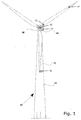
- a wind turbine 90 comprises a tower 92, a nacelle 94 at the tower top, the nacelle housing machine components, such as gearbox, generator etc. (not shown).
- a hub section 96 supports a plurality of wind turbine blades 10.
- the rotor of the wind turbine includes the blades and possibly other rotating parts such as the hub section 96.
- One or more measuring units 12 may be provided on the hub section 96, in or on the nacelle, in one or more of the blades 10, and in the tower 92.
- the measuring unit(s) 12 is/are arranged to measure one or more operational parameters representing a loading on the wind turbine rotor exerted by the wind, such as an acceleration of a component of the wind turbine, a load of a component of the wind turbine, a deflection of a component of the wind turbine, or a rotational speed of a component of the wind turbine.
- the load measurement may e.g. be a torque measurement at the hub or a stress in the blade root and carried out by suitable means, such as strain gauges, optical fibres etc.
- the acceleration measurement may be performed by means of an accelerometer arranged within the hub section, on the nacelle, or on the main shaft.
- the deflection measurement may be performed e.g. by an angle measurement device.
- the rpm measurement may conveniently be performed on the main shaft of the turbine or on a rotatable part within the hub section, to measure the rotational speed of the rotor. Alternatively, it may be performed by an instrument, which is independent of access to the main shaft of the wind turbine.
- FIG. 2 generally illustrates a control system of an embodiment of a wind turbine according to the invention.
- the wind turbine comprises one or more controllers such as a nacelle-hosed controller 18 within the nacelle 94 and a hub-sided controller 14 and in communication with each other via an interface between the stationary and the rotating parts.
- the controllers 14, 18 receive input from the set of sensors or measuring units 12 placed in different parts of the wind turbine such as in the nacelle, in the blades or the tower.
- the measuring units 12 may provide input data to the nacelle-housed controller 18 related to e.g. power output of the wind turbine, wind direction, wind velocity and/or other parameters.
- the hub-sited control circuitry 14 receives input data from a plurality of measuring units 12 arranged to measure e.g.
- the control system comprises a pitch controller for determining the pitch reference value for controlling the pitch of the blades 10.
- the input from the measuring units 12 is processed in a processor in one or more of the controllers to yield the operational parameter (such as the thrust coefficient or the minimum pitch limit value) and the variation parameter, and thereby determine whether or not a modified control strategy should be followed which is then communicated to the pitch controller.
- the pitch controller is then configured to optionally modify the otherwise decided pitch reference and control the pitch of the turbine blades accordingly.
- Figure 3 shows at the two uppermost curves the absolute wind speed V wind , 101 and the wind direction a wind , 102 as a function of time t, 103 during a wind load condition case.
- This specific case illustrates the wind parameters during an Extreme Coherent gust with Direction change load case (ECD) as prescribed in the IEC 61400 code which comprises a range of extreme wind load conditions typically considered in the design of a wind turbine to assure its structural integrity.
- ECD Extreme Coherent gust with Direction change load case
- the two lowermost curves show the rotor power coefficient Cp , 104 and the tilt moment M tilt , 105 for a pitch regulated variable speed wind turbine with a conventional yaw system based on wind vane measurements during and resulting from the extreme wind speed and direction change.
- the rotor power coefficient Cp , 104 can hence be calculated and estimated continuously based on the wind speed and the produced rotor power by the wind turbine as known by a person skilled in the art.
- the wind speed may be measured e.g. through a nacelle mounted anemometer (mechanical based or ultrasonic), or may be estimated e.g. through hub or blade mounted pressure probes.
- This method involves the measurements of the pitch angle ⁇ , the rotor speed ⁇ R , and the rotor power P ROT (generator output estimated mechanical and electrical drive train losses plus acceleration power).
- the control method according to the invention and as described in details in the following may hence in general be based equally well on the rotor torque coefficient instead of on the rotor power coefficient.
- the high tilt moments may arise for instance due to the generator speed-based pitch control being a relatively slow-acting system unable to follow the steep slopes of the wind speed, or not being designed to react on fast changing wind conditions. Therefore, the thrust coefficient may not be lowered fast enough to compensate for the increased wind speed. As a result, the tower is deflected backwards with the result of excessive tilt moments and bending moments in the tower base. Further, a tilt-yaw controller on the wind turbine may not react fast enough to be able to compensate for the abrupt change in the wind direction resulting in unbalanced loads and moments, and stationary yaw errors leading to the wind turbine being stopped. Similarly, the yaw moments of the hub (i.e. a load moment about an axis which is substantially parallel to and coinciding with a longitudinal direction defined by the tower construction of the wind turbine) may be excessive in extreme wind conditions as described here.
- the yaw moments of the hub i.e. a load moment about an axis which is substantially parallel to and coin
- this is however too late to avoid the large tilt moments M tilt , firstly as the tilt moments are already excessive at this time, and secondly as the stopping process in itself takes some time to take effect.
- the controlling strategy of the wind turbine is modified in case a variation parameter Avar being a function of the rotor power coefficient and reflecting a variation hereof over time becomes larger than some alert threshold T .
- the control and operation of the wind turbine is not altered, and the wind turbine is controlled as otherwise determined and according to the control signals received from the one or more controllers, such as power or torque reference signals for controlling the rotational speed of the wind turbine rotor, or pitch reference signals for controlling the pitching of one or more of the wind turbine blades.
- the modified control strategy initiated by the variation parameter exceeding the alert threshold may for instance comprise stopping the wind turbine (e.g. by braking or pitching the blades out of the wind according to some stopping strategy), or de-rating the turbine.
- a de-rating control strategy may e.g.
- the modified control strategy may comprise adding a modification parameter to the control signal such as for instance increasing the pitch by a certain extra amount.
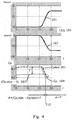
- FIG 4 shows the earliest part of the same wind load case as in figure 3 , with the wind speed V wind , 101 and wind direction a wind , 102 as a function of time t, 103.
- One of the curves below show the rotor power coefficient Cp, 104 in a solid thick line as also shown in figure 3 , and resulting from the wind load condition parameters during normal operation of the wind turbine and estimated or calculated directly or indirectly from the wind turbine power and wind speed as previously described.
- the controlling of the wind turbine is modified in case a variation parameter Avar being a function of the rotor power coefficient and reflecting a variation hereof over time becomes larger than some alert threshold T .
- the speed of the filter (fast or slow) is determined by the magnitude of the time constant. In this embodiment the slow averaging is done using a first order low pass filter on Cp with a time constant of 30 s. The fast averaging is done using the same filter with a time constant of 1 s.
- the time dependent variation of the rotor power coefficient may be determined by applying other types of filters such as filters of higher order, a Kalman filter or by the application of Fast Fourier transformation.
- the time dependent variation may further be determined as a function of the standard deviation and/or a mean value of the operational parameter.
- the time intervals at which the operational parameter and its variation are determined may vary according to need and can for instance be determined continuously or at varying interval lengths dependent for instance on the turbulence conditions, on the current wind direction, on the ambient temperature etc.
- the alert threshold may be chosen as a function of parameters directly or indirectly indicating the severity of the wind load condition or load conditions of the turbine, such as for example the current wind speed and wind direction, a turbulence factor, or e.g. current loads or moments in some of the wind turbine components, or the current pitching or pitching history.
- an alert threshold T may be used depending on the current pitch of the blades. In case the blades are pitched more into the wind, a relatively sudden change in the wind load conditions would cause higher loads on the rotor blades than if the blades were initially pitched out of the wind.
- an alert threshold T could advantageously be expressed as a function of the pitch such that the control strategy of the wind turbine would be more likely to be altered or modified (a lower T ) e.g. by stopping or de-rating, when the risk of intolerable loads caused by changes in the wind conditions is higher.
- Figure 5 shows, from the top, the wind speed 101, the electrical power on the generator side P 301, rotor power coefficient Cp 104, and the tilt moment M tilt 105 as a function of time t, 103, and during the same wind load condition of wind speed and direction change as previously illustrated in the figures 3 and 4 .
- the stopping based on the rotor power coefficient is hence initiated 8 seconds earlier than by the conventional control method based on yaw error supervision from wind vane measurements. As can be seen from the figure, the stopping is thereby initiated sufficiently early to avoid the otherwise resulting large tilt moments.
- Figure 6 shows a time series with normal production and with the control method implemented according to the above.
- the wind speed 401 and the wind direction 402 as a function of time are shown in the two first curves, which wind load conditions result in the rotor power coefficient by the solid (grey) line in the lowermost curve 403.
- a black dashed line is shown the rotor power coefficient filtered with a fast lowpass filter Cp fast , 404 and which is nearly coinciding with the unfiltered Cp .
- the dotted line 405 shows the rotor power coefficient filtered with a slow lowpass filter and minus an alert threshold; ( C P,slow -T ) similar to the curves in figure 4 .
- variation parameter Avar may alternatively or additionally be determined based on the rotor torque coefficient of the wind turbine due to its direct relationship to the rotor power coefficient via the tip-speed ratio ⁇ .
- the variation parameter Avar is determined based on the estimated thrust force F T on the wind turbine rather than, or in addition to the rotor power coefficient.
- the thrust F T may be determined or estimated from the wind speed, the pitch angle and the rotor or generator rotational speed. In general it may be shown that the thrust decreases with increasing pitch angles.
- the variation parameter Avar may be determined based on the thrust coefficient of the wind turbine rather than, or in addition to the rotor power coefficient.
- the thrust may e.g. be estimated from the rotor power, the rotor and/or generator speed, the pitch of the blades, and optionally based on look-up tables.
- the rotor power coefficient Cp seems to be sensitive not only to the wind direction changes but also to the variation in the wind speed.
- the rotor power coefficient in general seems to fluctuate more at lower wind speeds.
- a similar effect is seen on the thrust coefficient.
- the variation parameter Avar may therefore in embodiments of the invention also be expressed as a function of other sensor signals or measured parameters such as the current wind speed, the pitch of the blades, the drive train speed, or the acceleration of the nacelle. Thereby a better tuning of the variation parameter may be obtained and a higher confidence that the modified control strategy is not initiated during normal operation of the wind turbine
- the operational parameter may be chosen as the pitch limit ⁇ min ensuring that the thrust on the wind turbine is below a specified maximum allowable limit F t,max .
- the pitch limit therefore is similar to e.g. the aerodynamic thrust which represents the loading on the wind turbine as exerted by the wind.
- This pitch limit is also referred to as the thrust limiter pitch. It can be shown that the pitch angle ⁇ min , 800 for a given thrust value may be expressed as a linear function of the rotor power P rot 810 as illustrated in figure 8 .
- the minimum pitch 800 corresponding to a certain fixed maximum allowable thrust is shown as a function of the rotor power P rotor , 810 and for 4 different values of rotational speed of the rotor ⁇ , 801, 802, 803, 804.
- the rotor rotational speed increases for increasing pitch at a given rotor power.
- Such relationship may be determined for different values of rotor thrust F t,max from which a minimum pitch limit ⁇ min 800 may then be determined based on information of the generator power P generator , 810 and the rotational velocity of the rotor co, 801-804 by interpolation.
- the rotor power may be determined from data on the generator power and the rotor rotational speed.
- a thrust limiter pitch may be determined such that a certain maximum acceptable and allowable thrust is not exceeded.
- the maximum rotor thrust F t,max may be set at a predefined and/or constant level. Alternatively or additionally, the maximum rotor thrust F t,max may be variable and determined continuously or for certain time periods as the maximum acceptable thrust under the given wind conditions in order not to cause too high wear and fatigue on the wind turbine thereby reducing its life time while on the same time obtaining the desired power production over time.
- the maximum allowable rotor thrust F t,max may be determined from look-up tables or curves which have been predetermined e.g. during the designing of the wind turbine from simulations and in dependence of e.g. the current mean wind speed, the variation of the turbine blade loads, and/or the variation of the rotor acceleration.
- the variation parameter in this way reflects a sudden or abrupt change of the operational parameter expressing whether the thrust limiter pitch angle deviates or changes significantly relative to previous values.
- the variation parameter may in an embodiment be determined only as a function of the standard deviation or the mean value of the thrust limiter pitch, or may be determined e.g. as the difference between the change in the operational parameter in two successive time steps and the standard deviation (optionally times a constant).
- the modified control strategy may comprise adding a pitch contribution ⁇ (a modification parameter) to the pitch reference.
- the modified control strategy may imply adding a pitch contribution to the thrust limiter pitch, which may be used as the resulting pitch reference, in the cases where the otherwise determined pitch reference is below the thrust limiter pitch ⁇ min .
- the turbine blades are pitched out of the wind fast and hence effectively reducing the effective thrust force exerted on the rotor and thereby on the tower.
- the modification parameter added to the control signal value may be tuneable for example depending on the current wind speed, such that the blades may be pitched out of the wind faster at higher wind speeds where the tower bending moments would otherwise be relatively higher than at lower wind speeds.
- Figure 9 shows a time series with, 901 and without, 902 the control method implemented according to the above and during a simulation of a wind gust.
- the wind speed 101 as a function of time t is shown in the first curve, which wind load condition results in the pitch reference ⁇ , 500 (the control signal) and the tower bottom bending moments M , 904 as shown in the two lowermost curves with (dotted lines 901) and without (solid lines 902) implementing the modified control strategy according to the invention.
- the proposed control method only actively affects the control signal(s) such as the pitch reference in the situations where the large and sudden changes to the operational parameter such as the thrust limiter pitch or thrust coefficient are detected. It can be seen from figure 9 that the proposed control method of modifying the pitch is not active in the first time period until approximately t ⁇ 12 s, as the pitch reference 500 for the two different control methods are here the same. At the time t ⁇ 12 s large variations in the thrust limiter pitch (not shown) causes a change in pitch ⁇ , 903 (modification parameter) to be added to the otherwise determined pitch reference.
- This modification of the pitch reference results in considerably lower tower bottom bending moments as can be seen from the lowermost curve although the modified control strategy is only active and the pitch reference is modified for a very short period of time of around 12 s ⁇ t ⁇ 14 s. Further, as can be seen from the curve showing the modification parameter ⁇ , 903 the pitch in this embodiment is modified by a tuneable or variable parameter, where the pitch is initially increased by 6° and thereafter by a exponentially decreasing amount over the following time period of approximately one second.
- Figure 10 illustrates the same parameters as in figure 9 resulting from a simulation of the wind turbine behaviour during a time series of extreme turbulence with significant but constant level of wind fluctuations.
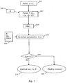
- control method is illustrated step-by-step in the flowchart in figure 7 and as applied to a pitch control parameter.
- the principle is however the same for other controllable parameters such as for control signals comprising the power reference etc.
- a new control signal ⁇ is received from another controller or determined locally, 500.
- information is received or obtained on the current rotor or generator power P and other wind turbine parameters such as the tip speed ratio, the wind speed Vwind, etc, 501. From these parameters the current operational parameter is then determined which as previously discussed is a parameter representing the loading on the wind turbine such as e.g.
- the variation parameter Avar reflecting a variation of the operational parameter is then determined 504 e.g. from the standard deviation and/or the variance or mean of the parameter, from a rain flow count algorithm, by filtering, or by similar data processing measures reflecting the fluctuation of the parameter over time.
- the variation parameter may alternatively or additionally also be determined as a function of other current parameters such as the current pitch angle, the wind speed, the drive train speed V drive , the blade loads, tower acceleration acc etc., 505.
- the variation parameter Avar does not exceed the alert threshold T (which may be a predefined constant or a function of current operating conditions such as the current wind speed) the wind turbine is controlled according to the control signal ⁇ 500 without any intervention 510.
- the present control strategy is overruled and the wind turbine is controlled according to a modified control strategy, 520.
- the modified control strategy may as previously mentioned for instance involve stopping the wind turbine, slowing the wind turbine down, or continue to control the wind turbine according to the previous or an even earlier control signal.
- the modified control strategy may likewise comprises increasing the thrust limiter pitch ⁇ min and/or the pitch reference ⁇ , 500 by certain amount ⁇ .
- the control method may involve storing the information on the operational parameter such as the rotor power coefficients and/or thrust coefficients optionally together with information on the associated control signals in a control history. Therefore, there is a possibility of letting the variation parameter Avar be a more complex function of the operational parameters, and control signals in the control history, such as depending on for instance the second derivatives or higher of the parameters.
Claims (13)
- Procédé de commande d'une éolienne ayant un rotor avec des pales d'éolienne inclinables et un générateur pour produire de l'énergie, le procédé comprenant les étapes consistant à :déterminer un signal de commande pour un paramètre ajustable de l'éolienne ;estimer à intervalles de temps au moins un paramètre opérationnel représentant une charge sur l'éolienne exercée par le vent, où l'étape d'estimation du paramètre opérationnel comprend l'estimation d'au moins l'un ou l'autre d'un coefficient de puissance de rotor, d'un coefficient de couple, d'un coefficient de poussée de l'éolienne et/ou d'un angle d'inclinaison limiteur de poussée, et dans lequel l'angle d'inclinaison limiteur de poussée comprend l'angle d'inclinaison minimal pour maintenir la poussée sur l'éolienne afin qu'elle soit égale ou inférieure à un niveau de poussée autorisé maximal ;déterminer un paramètre de variation reflétant une variation dudit paramètre opérationnel au fil du temps ;commander l'éolienne selon le signal de commande uniquement si le paramètre de variation se situe en dessous d'un seuil d'alerte ; etcommander l'éolienne selon une stratégie de commande modifiée si le paramètre de variation se situe au-dessus du seuil d'alerte.
- Procédé de commande selon la revendication 1, dans lequel la stratégie de commande modifiée comprend au moins l'une ou l'autre d'une situation d'arrêt, de déclassement de l'éolienne et d'addition d'un paramètre de modification à la valeur du signal de commande.
- Procédé selon la revendication 2, dans lequel le signal de commande comprend un signal de référence d'inclinaison pour commander l'inclinaison des pales de l'éolienne et la stratégie de commande modifiée comprend l'augmentation de la valeur du signal de référence d'inclinaison.
- Procédé de commande selon la revendication 2 ou la revendication 3, dans lequel le paramètre de modification est une constante prédéterminée.
- Procédé de commande selon l'une quelconque des revendications précédentes, dans lequel ledit au moins un paramètre opérationnel est déterminé parmi au moins l'une ou l'autre d'une vitesse du rotor, d'une vitesse du générateur de l'éolienne et de la vitesse du vent.
- Procédé de commande selon la revendication 1, dans lequel ledit au moins l'un ou l'autre du coefficient d'énergie du rotor, du coefficient de couple et du coefficient de poussée est déterminé à partir d'un angle d'inclinaison d'une ou plusieurs des pales de l'éolienne.
- Procédé de commande selon l'une quelconque des revendications précédentes, dans lequel le paramètre de variation est déterminé en fonction de la différence entre un paramètre opérationnel de filtre passe-bas rapide et un paramètre opérationnel de filtre passe-bas lent.
- Procédé de commande selon l'une quelconque des revendications précédentes, dans lequel le paramètre de variation est déterminé en fonction d'au moins l'un(e)ou l'autre de la valeur moyenne et de l'écart type du paramètre opérationnel.
- Procédé de commande selon l'une quelconque des revendications précédentes, dans lequel le paramètre de variation est déterminé en fonction d'un angle d'inclinaison d'une ou plusieurs des pales d'éolienne, de l'accélération de la tour de l'éolienne et/ou de la vitesse du train d'entraînement de l'éolienne.
- Procédé de commande selon l'une quelconque des revendications précédentes, dans lequel le seuil d'alerte est une constante prédéterminée.
- Procédé de commande selon l'une quelconque des revendications précédentes, dans lequel le seuil d'alerte est fonction de la vitesse du vent.
- Système de commande pour une éolienne ayant un rotor avec des pales d'éolienne inclinables et un générateur pour produire de l'énergie, le système de commande étant configuré pour effectuer les étapes consistant à :déterminer un signal de commande pour un paramètre ajustable de l'éolienne ;estimer à intervalles de temps au moins un paramètre opérationnel représentant une charge sur l'éolienne exercée par le vent, où l'étape d'estimation du paramètre opérationnel comprend l'estimation d'au moins l'un ou l'autre d'un coefficient de puissance de rotor, d'un coefficient de couple, d'un coefficient de poussée de l'éolienne et/ou d'un angle d'inclinaison limiteur de poussée, et dans lequel l'angle d'inclinaison limiteur de poussée comprend l'angle d'inclinaison minimal pour maintenir la poussée sur l'éolienne afin qu'elle soit égale ou inférieure à un niveau de poussée autorisé maximal ;déterminer un paramètre de variation reflétant une variation dudit paramètre opérationnel au fil du temps ;commander l'éolienne selon le signal de commande uniquement si le paramètre de variation se situe en dessous d'un seuil d'alerte ; etcommander l'éolienne selon une stratégie de commande modifiée si le paramètre de variation se situe au-dessus du seuil d'alerte.
- Eolienne ayant un rotor avec des pales d'éolienne inclinables et un générateur pour produire de l'énergie et comprenant une unité de mesure placée par rapport au rotor de manière à mesurer à intervalles de temps au moins un paramètre opérationnel représentant une charge sur le rotor d'éolienne exercée par le vent, l'éolienne comprenant en outre un système de commande selon la revendication 12 comprenant un contrôleur pour déterminer un signal de commande pour un paramètre ajustable de l'éolienne, un processeur pour déterminer ledit au moins un paramètre opérationnel tel que mesuré par l'unité de mesure et pour déterminer un paramètre de variation reflétant une variation dudit paramètre opérationnel au fil du temps, et dans laquelle le contrôleur est encore configuré pour commander l'éolienne selon le signal de commande uniquement si le paramètre de variation se situe en dessous d'un seuil d'alerte et selon une stratégie de commande modifiée si le paramètre de variation se situe au-dessus du seuil d'alerte.
Applications Claiming Priority (5)
| Application Number | Priority Date | Filing Date | Title |
|---|---|---|---|
| US24988509P | 2009-10-08 | 2009-10-08 | |
| DKPA200901106 | 2009-10-08 | ||
| US35617910P | 2010-06-18 | 2010-06-18 | |
| DKPA201070274A DK201070274A (en) | 2009-10-08 | 2010-06-18 | Control method for a wind turbine |
| PCT/EP2010/064666 WO2011042369A2 (fr) | 2009-10-08 | 2010-10-01 | Procédé de commande d'éolienne |
Publications (2)
| Publication Number | Publication Date |
|---|---|
| EP2486272A2 EP2486272A2 (fr) | 2012-08-15 |
| EP2486272B1 true EP2486272B1 (fr) | 2016-03-23 |
Family
ID=43854229
Family Applications (1)
| Application Number | Title | Priority Date | Filing Date |
|---|---|---|---|
| EP10765998.9A Active EP2486272B1 (fr) | 2009-10-08 | 2010-10-01 | Procédé de commande d'éolienne |
Country Status (7)
| Country | Link |
|---|---|
| US (1) | US7964979B2 (fr) |
| EP (1) | EP2486272B1 (fr) |
| CN (1) | CN102648345B (fr) |
| DK (1) | DK201070274A (fr) |
| ES (1) | ES2569235T3 (fr) |
| IN (1) | IN2012DN03805A (fr) |
| WO (1) | WO2011042369A2 (fr) |
Families Citing this family (75)
| Publication number | Priority date | Publication date | Assignee | Title |
|---|---|---|---|---|
| US8041540B2 (en) * | 2009-12-09 | 2011-10-18 | General Electric Company | System, device, and method for acoustic and visual monitoring of a wind turbine |
| DK177434B1 (en) * | 2010-06-18 | 2013-05-21 | Vestas Wind Sys As | Method for controlling a wind turbine |
| EP2705251B1 (fr) | 2011-05-04 | 2017-01-04 | Condor Wind Energy Limited | Pont d'atterrissage d'hélicoptère |
| WO2013027127A2 (fr) | 2011-05-06 | 2013-02-28 | Condor Wind Energy Limited | Systèmes destinés à réduire au minimum le couple d'orientation nécessaire pour commander la puissance de sortie d'éoliennes bipales, à articulation de bascule qui commandent la puissance de sortie par orientation |
| WO2012153197A2 (fr) | 2011-05-10 | 2012-11-15 | Condor Wind Energy Limited | Articulation de bascule élastomère |
| DK2712403T3 (da) * | 2011-05-11 | 2022-01-24 | Seawind Ocean Tech Holding Bv | Effektstyringssystem til giringsstyrede vindmøller |
| US10495060B2 (en) | 2011-05-27 | 2019-12-03 | Seawind Ocean Technology Holding Bv | Wind turbine control system having a thrust sensor |
| DE102011054211B3 (de) * | 2011-10-05 | 2013-01-10 | Kenersys Gmbh | Verfahren zum Betreiben einer Windenergieanlage und entsprechende Windenergieanlage |
| EP2786017B1 (fr) | 2011-11-21 | 2017-04-12 | Vestas Wind Systems A/S | Commande d'arrêt et procédé d'arrêt d'une éolienne |
| US9014861B2 (en) * | 2011-12-20 | 2015-04-21 | General Electric Company | Method and system for noise-controlled operation of a wind turbine |
| CN104246466B (zh) | 2011-12-30 | 2018-01-02 | 维斯塔斯风力系统集团公司 | 估计和控制结构中经受的负荷 |
| EP2850317B1 (fr) * | 2012-05-18 | 2017-12-06 | ROMO Wind AG | Procédé pour controler l'angle d'inclinaison d'au moins une pale de turbine éolienne |
| WO2013182200A1 (fr) * | 2012-06-06 | 2013-12-12 | Vestas Wind Systems A/S | Turbine éolienne ayant une unité de commande de charge |
| DK201270417A (en) | 2012-07-09 | 2014-01-10 | Envision Energy Denmark Aps | Method and System to Actively Pitch to Reduce Extreme Loads on Wind Turbine |
| DE102012108776A1 (de) * | 2012-09-18 | 2014-03-20 | Technische Universität München | Verfahren und Vorrichtung zur Überwachung von Betriebszuständen von Rotorblättern |
| US9341159B2 (en) | 2013-04-05 | 2016-05-17 | General Electric Company | Methods for controlling wind turbine loading |
| US8803352B1 (en) | 2013-05-14 | 2014-08-12 | General Electric Compay | Wind turbines and methods for controlling wind turbine loading |
| US9416771B2 (en) | 2013-06-26 | 2016-08-16 | Siemens Aktiengesellschaft | Method for controlling loads in a wind turbine |
| US9551321B2 (en) * | 2013-06-26 | 2017-01-24 | General Electric Company | System and method for controlling a wind turbine |
| US10378512B2 (en) | 2013-07-30 | 2019-08-13 | Vestas Wind Systems A/S | Wind turbine operating method and device based on load and acceleration measurements in the blade |
| US10371123B2 (en) | 2013-08-19 | 2019-08-06 | General Electric Company | Methods and systems for detecting wind turbine rotor blade damage |
| WO2015032410A1 (fr) | 2013-09-05 | 2015-03-12 | Vestas Wind Systems A/S | Système de sécurité pour une éolienne |
| US9624905B2 (en) | 2013-09-20 | 2017-04-18 | General Electric Company | System and method for preventing excessive loading on a wind turbine |
| WO2015065425A1 (fr) | 2013-10-31 | 2015-05-07 | General Electric Company | Système et procédé permettant de réguler des systèmes de génération de puissance éolienne |
| DK2886856T3 (da) * | 2013-12-20 | 2020-01-02 | Siemens Gamesa Renewable Energy As | Detektering af pitchvinkeljusteringsfejl |
| CN103835879B (zh) * | 2014-02-11 | 2017-04-12 | 南京南瑞继保电气有限公司 | 一种基于反时限的风机偏航启动判别方法 |
| WO2015135549A1 (fr) * | 2014-03-12 | 2015-09-17 | Vestas Wind Systems A/S | Procédé de commande pour turbine éolienne |
| US9631606B2 (en) * | 2014-04-14 | 2017-04-25 | General Electric Company | System and method for thrust-speed control of a wind turbine |
| ES2728685T3 (es) * | 2014-06-20 | 2019-10-28 | Mita Teknik As | Sistema de limitación de empuje de turbinas eólicas |
| EP3180514B1 (fr) * | 2014-08-15 | 2019-11-20 | Vestas Wind Systems A/S | Commande d'une éolienne présentant un état de défaillance |
| US10036692B2 (en) | 2014-11-13 | 2018-07-31 | General Electric Company | System and method for estimating rotor blade loads of a wind turbine |
| US9909563B2 (en) * | 2014-11-21 | 2018-03-06 | General Electric Company | System and method for monitoring and controlling wind turbine blade deflection |
| CN107002637B (zh) * | 2014-11-21 | 2019-03-22 | 维斯塔斯风力系统集团公司 | 一种用于以稳定的方式估计风速的方法 |
| EP3221582B1 (fr) | 2014-11-21 | 2021-04-21 | Vestas Wind Systems A/S | Procédé d'estimation d'une vitesse de vent comprenant le calcul d'un angle de tangage réglé pour torsion de pale |
| US9798343B2 (en) * | 2014-11-25 | 2017-10-24 | Rockwell Automation Technologies, Inc. | Quantifying operating strategy energy usage |
| US9863402B2 (en) | 2015-02-13 | 2018-01-09 | General Electric Company | System and method for operating a wind turbine based on rotor blade margin |
| CN104763586B (zh) * | 2015-04-03 | 2017-06-16 | 内蒙古工业大学 | 用于风力发电机组的控制方法及设备 |
| EP3088733B1 (fr) * | 2015-04-27 | 2018-10-17 | Envision Energy (Jiangsu) Co., Ltd. | Procédé pour faire fonctionner une éolienne sur la base de la dégradation de la pale de turbine éolienne |
| CN106812658B (zh) * | 2015-11-27 | 2019-09-06 | 中国船舶重工集团海装风电股份有限公司 | 一种风力发电机组的控制方法及装置 |
| WO2017108062A1 (fr) | 2015-12-23 | 2017-06-29 | Vestas Wind Systems A/S | Procédé de commande pour une éolienne |
| JP6405324B2 (ja) * | 2016-01-29 | 2018-10-17 | 三菱重工業株式会社 | 風力発電装置及びその運転方法 |
| DK179221B1 (en) * | 2016-03-18 | 2018-02-12 | Mita Teknik As | High Yaw Error and Gust Ride Through |
| US10890159B2 (en) | 2016-08-17 | 2021-01-12 | Vestas Wind Systems A/S | Dynamic controlled wind turbine shutdown |
| DE102016117191A1 (de) * | 2016-09-13 | 2018-03-15 | fos4X GmbH | Verfahren und Vorrichtung zur Ermittlung von Belastungen auf einen Turm einer Windenergieanlage |
| CN110177934B (zh) * | 2016-11-14 | 2021-09-14 | 维斯塔斯风力系统集团公司 | 风力涡轮机的噪声分析与控制 |
| EP3343025A1 (fr) * | 2016-12-30 | 2018-07-04 | Acciona Windpower, S.A. | Procédé de réduction des charges agissant sur un système de lacets d'éolienne |
| CN107061160A (zh) * | 2017-04-26 | 2017-08-18 | 浙江运达风电股份有限公司 | 一种基于叶片载荷检测的风力发电机组叶片冰载运行安全控制方法及系统 |
| US10634121B2 (en) | 2017-06-15 | 2020-04-28 | General Electric Company | Variable rated speed control in partial load operation of a wind turbine |
| DE102017121563A1 (de) | 2017-09-18 | 2019-03-21 | Wobben Properties Gmbh | Windenergieanlage und Verfahren zum Betreiben einer Windenergieanlage |
| US10570883B2 (en) * | 2017-12-22 | 2020-02-25 | General Electric Company | System and method for protecting wind turbines during wind gusts |
| WO2019185560A1 (fr) * | 2018-03-29 | 2019-10-03 | Mhi Vestas Offshore Wind A/S | Générateur d'éolienne et procédé de commande de générateur d'éolienne |
| DE102018113706A1 (de) * | 2018-06-08 | 2019-12-12 | Wobben Properties Gmbh | Verfahren zum Betreiben einer Windenergieanlage, Windenergieanlage und Windpark |
| US11319926B2 (en) * | 2018-10-22 | 2022-05-03 | General Electric Company | System and method for protecting wind turbines from extreme and fatigue loads |
| EP3899249B1 (fr) * | 2018-12-20 | 2023-09-27 | Vestas Wind Systems A/S | Correction de l'angle de pas |
| EP3680479B1 (fr) | 2019-01-08 | 2021-06-09 | Nordex Energy SE & Co. KG | Procédé de fonctionnement d'une éolienne |
| ES2937953T3 (es) * | 2019-03-04 | 2023-04-03 | Ge Renewable Germany Gmbh | Límites de empuje para turbinas eólicas |
| US11293403B2 (en) * | 2019-04-09 | 2022-04-05 | General Electric Company | System and method for preventing catastrophic damage in drivetrain of a wind turbine |
| DK180760B1 (en) | 2019-05-29 | 2022-02-24 | Envision Energy Jiangsu Co Ltd | A wind turbine and a method of operating the wind turbine |
| CN112392656B (zh) * | 2019-08-16 | 2022-03-29 | 北京金风科创风电设备有限公司 | 风力发电机组的功率控制方法、装置以及介质 |
| CN112746927B (zh) * | 2019-10-30 | 2022-08-23 | 北京金风科创风电设备有限公司 | 风力发电机组的变桨控制方法、装置、系统及介质 |
| CN110778451B (zh) * | 2019-11-15 | 2021-11-23 | 东方电气风电有限公司 | 一种大型风力发电机组安全保护方法及系统 |
| CN110966144B (zh) * | 2019-12-04 | 2020-10-30 | 浙江大学 | 一种基于bls的风电机组智能恒功率控制方法 |
| CN111396249B (zh) * | 2020-03-31 | 2022-08-30 | 新疆金风科技股份有限公司 | 在阵风风况下降低塔架的载荷的方法及装置 |
| CN113494418A (zh) | 2020-04-08 | 2021-10-12 | 通用电气可再生能源西班牙有限公司 | 用于减轻作用于风力涡轮的转子叶片的负载的系统和方法 |
| EP3919737A1 (fr) * | 2020-06-05 | 2021-12-08 | Siemens Gamesa Renewable Energy A/S | Dispositif et procédé de commande du fonctionnement d'une éolienne pour réduire la charge au désalignement du lacet |
| CN116057274A (zh) * | 2020-07-10 | 2023-05-02 | 维斯塔斯风力系统集团公司 | 对风力涡轮机塔架横向振荡控制进行 |
| CN113090455B (zh) * | 2021-04-25 | 2022-05-24 | 中国华能集团清洁能源技术研究院有限公司 | 在电网掉电条件下风电机组桨距角控制方法、系统和设备 |
| CN113482862B (zh) * | 2021-07-07 | 2022-10-18 | 陕西中科启航科技有限公司 | 一种风电机组运行状态监控方法及系统 |
| CN113464379B (zh) * | 2021-07-19 | 2024-03-26 | 陕西中科启航科技有限公司 | 一种漂浮式海上风电机组运行状态监控方法 |
| CN113374633B (zh) * | 2021-07-27 | 2023-01-03 | 中国华能集团清洁能源技术研究院有限公司 | 一种风力发电机组控制输入信号的处理方法与系统 |
| CN113586335B (zh) * | 2021-09-16 | 2022-07-19 | 中国华能集团清洁能源技术研究院有限公司 | 用于大湍流工况的风力发电机防超速组控制方法及系统 |
| CN113653596B (zh) * | 2021-09-23 | 2023-07-14 | 华北电力大学 | 基于模糊预测和扇区管理的双风轮风力机变桨控制方法 |
| CN114198267B (zh) * | 2021-11-08 | 2023-11-03 | 华能大理风力发电有限公司 | 用于极端阵风的风力发电机组的运行控制方法及系统 |
| CN115095481B (zh) * | 2022-06-27 | 2023-03-10 | 上海拜安传感技术有限公司 | 风力发电机独立变桨调整方法及调整系统 |
| CN115653831A (zh) * | 2022-11-11 | 2023-01-31 | 国家能源集团山西电力有限公司 | 一种风力发电机组应急偏航控制系统和方法 |
Family Cites Families (27)
| Publication number | Priority date | Publication date | Assignee | Title |
|---|---|---|---|---|
| US4357542A (en) * | 1979-07-12 | 1982-11-02 | Westinghouse Electric Corp. | Wind turbine generator system |
| US4474531A (en) * | 1982-12-27 | 1984-10-02 | U.S. Windpower, Inc. | Windmill with direction-controlled feathering |
| JP3235242B2 (ja) * | 1992-11-30 | 2001-12-04 | 株式会社明電舎 | 2慣性ねじり振動系の速度制御におけるイナーシャ推定方法 |
| US5798631A (en) * | 1995-10-02 | 1998-08-25 | The State Of Oregon Acting By And Through The State Board Of Higher Education On Behalf Of Oregon State University | Performance optimization controller and control method for doubly-fed machines |
| DE10033183C2 (de) | 2000-07-07 | 2002-08-08 | Max Planck Gesellschaft | Verfahren und Vorrichtung zur Verarbeitung und Vorhersage von Strömungsparametern turbulenter Medien |
| USH2057H1 (en) * | 2001-01-10 | 2003-01-07 | Sandia Corporation | Load attenuating passively adaptive wind turbine blade |
| US6866024B2 (en) * | 2001-03-05 | 2005-03-15 | The Ohio State University | Engine control using torque estimation |
| EP3032685A1 (fr) * | 2001-09-28 | 2016-06-15 | Wobben Properties GmbH | Procede de fonctionnement d'une eolienne |
| DE10232021B4 (de) | 2002-07-16 | 2016-05-04 | Markus Jansen | Verfahren zur Vorhersage von Windböen und der damit verbundenen Steuerung von Windenergieanlagen sowie Windenergieanlage zur Durchführung dieses Verfahrens |
| US20040096327A1 (en) * | 2002-11-14 | 2004-05-20 | Kari Appa | Method of increasing wind farm energy production |
| US7175389B2 (en) | 2004-06-30 | 2007-02-13 | General Electric Company | Methods and apparatus for reducing peak wind turbine loads |
| US7476985B2 (en) | 2005-07-22 | 2009-01-13 | Gamesa Innovation & Technology, S.L. | Method of operating a wind turbine |
| WO2007021992A2 (fr) * | 2005-08-12 | 2007-02-22 | Mariah Power Inc. | Turbine eolienne a faible cout |
| US7351033B2 (en) * | 2005-09-09 | 2008-04-01 | Mcnerney Gerald | Wind turbine load control method |
| US7393177B2 (en) * | 2005-11-04 | 2008-07-01 | Rahai Hamid R | Vertical axis wind turbine with optimized blade profile |
| US7488155B2 (en) | 2005-11-18 | 2009-02-10 | General Electric Company | Method and apparatus for wind turbine braking |
| US7345373B2 (en) * | 2005-11-29 | 2008-03-18 | General Electric Company | System and method for utility and wind turbine control |
| WO2007123552A1 (fr) * | 2006-04-26 | 2007-11-01 | Midwest Research Institute | Commande de pas adaptative pour turbines eoliennes a vitesse variable |
| ES2288121B1 (es) | 2006-05-31 | 2008-10-16 | GAMESA INNOVATION & TECHNOLOGY, S.L. | Metodo de operacion de un aerogenerador. |
| US7352076B1 (en) * | 2006-08-11 | 2008-04-01 | Mariah Power Inc. | Small wind turbine system |
| ES2701707T3 (es) * | 2007-05-03 | 2019-02-25 | Siemens Ag | Procedimiento de funcionamiento de un aerogenerador y aerogenerador |
| EP2191131B1 (fr) * | 2007-08-31 | 2017-12-20 | Vestas Wind Systems A/S | Procédé de commande d'au moins un mécanisme de réglage d'une éolienne, éolienne et parc éolien |
| US7999406B2 (en) | 2008-02-29 | 2011-08-16 | General Electric Company | Wind turbine plant high wind derating control |
| DE102008012957A1 (de) | 2008-03-06 | 2009-09-10 | Repower Systems Ag | Verfahren zum Betreiben einer Windenergieanlage und Windenergieanlage |
| DK2110551T4 (da) | 2008-04-15 | 2019-05-13 | Siemens Ag | Fremgangsmåde og indretning til prognose-baseret vindmøllestyring |
| US8093737B2 (en) | 2008-05-29 | 2012-01-10 | General Electric Company | Method for increasing energy capture in a wind turbine |
| US8096761B2 (en) * | 2008-10-16 | 2012-01-17 | General Electric Company | Blade pitch management method and system |
-
2010
- 2010-06-18 DK DKPA201070274A patent/DK201070274A/en not_active Application Discontinuation
- 2010-10-01 ES ES10765998.9T patent/ES2569235T3/es active Active
- 2010-10-01 WO PCT/EP2010/064666 patent/WO2011042369A2/fr active Application Filing
- 2010-10-01 US US12/895,932 patent/US7964979B2/en active Active
- 2010-10-01 CN CN201080055738.8A patent/CN102648345B/zh active Active
- 2010-10-01 IN IN3805DEN2012 patent/IN2012DN03805A/en unknown
- 2010-10-01 EP EP10765998.9A patent/EP2486272B1/fr active Active
Also Published As
| Publication number | Publication date |
|---|---|
| CN102648345B (zh) | 2015-01-07 |
| US20110084485A1 (en) | 2011-04-14 |
| WO2011042369A2 (fr) | 2011-04-14 |
| DK201070274A (en) | 2011-04-09 |
| CN102648345A (zh) | 2012-08-22 |
| IN2012DN03805A (fr) | 2015-08-28 |
| ES2569235T3 (es) | 2016-05-09 |
| EP2486272A2 (fr) | 2012-08-15 |
| US7964979B2 (en) | 2011-06-21 |
| WO2011042369A3 (fr) | 2011-11-10 |
Similar Documents
| Publication | Publication Date | Title |
|---|---|---|
| EP2486272B1 (fr) | Procédé de commande d'éolienne | |
| US8803351B2 (en) | Control method for a wind turbine | |
| EP2233736B1 (fr) | Procédé de commande d'éolienne et éolienne | |
| US8202048B2 (en) | Method of operating a wind turbine and wind turbine | |
| EP2860394B1 (fr) | Système et procédé permettant d'éviter une charge excessive sur une turbine éolienne | |
| EP2067989B1 (fr) | Système et procédé de commande d'une installation éolienne | |
| EP2056210B1 (fr) | Éolienne et méthode pour contrôler une éolienne | |
| EP2022981B1 (fr) | Procédé de fonctionnement d'un aérogénérateur | |
| EP2598750B1 (fr) | Perfectionnement apportés aux éoliennes | |
| EP2678556B1 (fr) | Système de sécurité pour turbine éolienne | |
| US9551321B2 (en) | System and method for controlling a wind turbine | |
| EP2256339B1 (fr) | Procédé de contrôle d'éolienne | |
| US8807937B2 (en) | Wind turbine | |
| EP3875756B1 (fr) | Système de surveillance de commande de pas de pale d'une éolienne | |
| CN113825903A (zh) | 用于基于变化元件来控制风力涡轮机的装置和方法 | |
| EP3643916B1 (fr) | Système et procédé de surveillance de l'état de pales de rotor d'éoliennes | |
| CN113795666A (zh) | 一种风力发电机及运行该风力发电机的方法 |
Legal Events
| Date | Code | Title | Description |
|---|---|---|---|
| PUAI | Public reference made under article 153(3) epc to a published international application that has entered the european phase |
Free format text: ORIGINAL CODE: 0009012 |
|
| 17P | Request for examination filed |
Effective date: 20120504 |
|
| AK | Designated contracting states |
Kind code of ref document: A2 Designated state(s): AL AT BE BG CH CY CZ DE DK EE ES FI FR GB GR HR HU IE IS IT LI LT LU LV MC MK MT NL NO PL PT RO RS SE SI SK SM TR |
|
| DAX | Request for extension of the european patent (deleted) | ||
| RAP1 | Party data changed (applicant data changed or rights of an application transferred) |
Owner name: VESTAS WIND SYSTEMS A/S |
|
| REG | Reference to a national code |
Ref country code: DE Ref legal event code: R079 Ref document number: 602010031447 Country of ref document: DE Free format text: PREVIOUS MAIN CLASS: F03D0007040000 Ipc: F03D0007020000 |
|
| GRAP | Despatch of communication of intention to grant a patent |
Free format text: ORIGINAL CODE: EPIDOSNIGR1 |
|
| RIC1 | Information provided on ipc code assigned before grant |
Ipc: F03D 7/04 20060101ALI20150908BHEP Ipc: F03D 7/02 20060101AFI20150908BHEP Ipc: G05B 13/02 20060101ALI20150908BHEP Ipc: H02P 9/04 20060101ALI20150908BHEP |
|
| INTG | Intention to grant announced |
Effective date: 20150928 |
|
| GRAS | Grant fee paid |
Free format text: ORIGINAL CODE: EPIDOSNIGR3 |
|
| GRAA | (expected) grant |
Free format text: ORIGINAL CODE: 0009210 |
|
| AK | Designated contracting states |
Kind code of ref document: B1 Designated state(s): AL AT BE BG CH CY CZ DE DK EE ES FI FR GB GR HR HU IE IS IT LI LT LU LV MC MK MT NL NO PL PT RO RS SE SI SK SM TR |
|
| REG | Reference to a national code |
Ref country code: GB Ref legal event code: FG4D |
|
| REG | Reference to a national code |
Ref country code: CH Ref legal event code: EP |
|
| REG | Reference to a national code |
Ref country code: AT Ref legal event code: REF Ref document number: 783438 Country of ref document: AT Kind code of ref document: T Effective date: 20160415 |
|
| REG | Reference to a national code |
Ref country code: IE Ref legal event code: FG4D |
|
| REG | Reference to a national code |
Ref country code: DE Ref legal event code: R096 Ref document number: 602010031447 Country of ref document: DE |
|
| REG | Reference to a national code |
Ref country code: ES Ref legal event code: FG2A Ref document number: 2569235 Country of ref document: ES Kind code of ref document: T3 Effective date: 20160509 |
|
| REG | Reference to a national code |
Ref country code: LT Ref legal event code: MG4D |
|
| REG | Reference to a national code |
Ref country code: NL Ref legal event code: MP Effective date: 20160323 |
|
| PG25 | Lapsed in a contracting state [announced via postgrant information from national office to epo] |
Ref country code: NO Free format text: LAPSE BECAUSE OF FAILURE TO SUBMIT A TRANSLATION OF THE DESCRIPTION OR TO PAY THE FEE WITHIN THE PRESCRIBED TIME-LIMIT Effective date: 20160623 Ref country code: FI Free format text: LAPSE BECAUSE OF FAILURE TO SUBMIT A TRANSLATION OF THE DESCRIPTION OR TO PAY THE FEE WITHIN THE PRESCRIBED TIME-LIMIT Effective date: 20160323 Ref country code: GR Free format text: LAPSE BECAUSE OF FAILURE TO SUBMIT A TRANSLATION OF THE DESCRIPTION OR TO PAY THE FEE WITHIN THE PRESCRIBED TIME-LIMIT Effective date: 20160624 Ref country code: HR Free format text: LAPSE BECAUSE OF FAILURE TO SUBMIT A TRANSLATION OF THE DESCRIPTION OR TO PAY THE FEE WITHIN THE PRESCRIBED TIME-LIMIT Effective date: 20160323 |
|
| REG | Reference to a national code |
Ref country code: AT Ref legal event code: MK05 Ref document number: 783438 Country of ref document: AT Kind code of ref document: T Effective date: 20160323 |
|
| PG25 | Lapsed in a contracting state [announced via postgrant information from national office to epo] |
Ref country code: RS Free format text: LAPSE BECAUSE OF FAILURE TO SUBMIT A TRANSLATION OF THE DESCRIPTION OR TO PAY THE FEE WITHIN THE PRESCRIBED TIME-LIMIT Effective date: 20160323 Ref country code: NL Free format text: LAPSE BECAUSE OF FAILURE TO SUBMIT A TRANSLATION OF THE DESCRIPTION OR TO PAY THE FEE WITHIN THE PRESCRIBED TIME-LIMIT Effective date: 20160323 Ref country code: LV Free format text: LAPSE BECAUSE OF FAILURE TO SUBMIT A TRANSLATION OF THE DESCRIPTION OR TO PAY THE FEE WITHIN THE PRESCRIBED TIME-LIMIT Effective date: 20160323 Ref country code: SE Free format text: LAPSE BECAUSE OF FAILURE TO SUBMIT A TRANSLATION OF THE DESCRIPTION OR TO PAY THE FEE WITHIN THE PRESCRIBED TIME-LIMIT Effective date: 20160323 Ref country code: LT Free format text: LAPSE BECAUSE OF FAILURE TO SUBMIT A TRANSLATION OF THE DESCRIPTION OR TO PAY THE FEE WITHIN THE PRESCRIBED TIME-LIMIT Effective date: 20160323 |
|
| REG | Reference to a national code |
Ref country code: FR Ref legal event code: PLFP Year of fee payment: 7 |
|
| PG25 | Lapsed in a contracting state [announced via postgrant information from national office to epo] |
Ref country code: PL Free format text: LAPSE BECAUSE OF FAILURE TO SUBMIT A TRANSLATION OF THE DESCRIPTION OR TO PAY THE FEE WITHIN THE PRESCRIBED TIME-LIMIT Effective date: 20160323 Ref country code: IS Free format text: LAPSE BECAUSE OF FAILURE TO SUBMIT A TRANSLATION OF THE DESCRIPTION OR TO PAY THE FEE WITHIN THE PRESCRIBED TIME-LIMIT Effective date: 20160723 Ref country code: EE Free format text: LAPSE BECAUSE OF FAILURE TO SUBMIT A TRANSLATION OF THE DESCRIPTION OR TO PAY THE FEE WITHIN THE PRESCRIBED TIME-LIMIT Effective date: 20160323 |
|
| PG25 | Lapsed in a contracting state [announced via postgrant information from national office to epo] |
Ref country code: AT Free format text: LAPSE BECAUSE OF FAILURE TO SUBMIT A TRANSLATION OF THE DESCRIPTION OR TO PAY THE FEE WITHIN THE PRESCRIBED TIME-LIMIT Effective date: 20160323 Ref country code: PT Free format text: LAPSE BECAUSE OF FAILURE TO SUBMIT A TRANSLATION OF THE DESCRIPTION OR TO PAY THE FEE WITHIN THE PRESCRIBED TIME-LIMIT Effective date: 20160725 Ref country code: SK Free format text: LAPSE BECAUSE OF FAILURE TO SUBMIT A TRANSLATION OF THE DESCRIPTION OR TO PAY THE FEE WITHIN THE PRESCRIBED TIME-LIMIT Effective date: 20160323 Ref country code: SM Free format text: LAPSE BECAUSE OF FAILURE TO SUBMIT A TRANSLATION OF THE DESCRIPTION OR TO PAY THE FEE WITHIN THE PRESCRIBED TIME-LIMIT Effective date: 20160323 Ref country code: RO Free format text: LAPSE BECAUSE OF FAILURE TO SUBMIT A TRANSLATION OF THE DESCRIPTION OR TO PAY THE FEE WITHIN THE PRESCRIBED TIME-LIMIT Effective date: 20160323 Ref country code: CZ Free format text: LAPSE BECAUSE OF FAILURE TO SUBMIT A TRANSLATION OF THE DESCRIPTION OR TO PAY THE FEE WITHIN THE PRESCRIBED TIME-LIMIT Effective date: 20160323 |
|
| PG25 | Lapsed in a contracting state [announced via postgrant information from national office to epo] |
Ref country code: BE Free format text: LAPSE BECAUSE OF FAILURE TO SUBMIT A TRANSLATION OF THE DESCRIPTION OR TO PAY THE FEE WITHIN THE PRESCRIBED TIME-LIMIT Effective date: 20160323 Ref country code: IT Free format text: LAPSE BECAUSE OF FAILURE TO SUBMIT A TRANSLATION OF THE DESCRIPTION OR TO PAY THE FEE WITHIN THE PRESCRIBED TIME-LIMIT Effective date: 20160323 |
|
| REG | Reference to a national code |
Ref country code: DE Ref legal event code: R097 Ref document number: 602010031447 Country of ref document: DE |
|
| PLBE | No opposition filed within time limit |
Free format text: ORIGINAL CODE: 0009261 |
|
| STAA | Information on the status of an ep patent application or granted ep patent |
Free format text: STATUS: NO OPPOSITION FILED WITHIN TIME LIMIT |
|
| PG25 | Lapsed in a contracting state [announced via postgrant information from national office to epo] |
Ref country code: DK Free format text: LAPSE BECAUSE OF FAILURE TO SUBMIT A TRANSLATION OF THE DESCRIPTION OR TO PAY THE FEE WITHIN THE PRESCRIBED TIME-LIMIT Effective date: 20160323 |
|
| PG25 | Lapsed in a contracting state [announced via postgrant information from national office to epo] |
Ref country code: BG Free format text: LAPSE BECAUSE OF FAILURE TO SUBMIT A TRANSLATION OF THE DESCRIPTION OR TO PAY THE FEE WITHIN THE PRESCRIBED TIME-LIMIT Effective date: 20160623 |
|
| 26N | No opposition filed |
Effective date: 20170102 |
|
| PG25 | Lapsed in a contracting state [announced via postgrant information from national office to epo] |
Ref country code: SI Free format text: LAPSE BECAUSE OF FAILURE TO SUBMIT A TRANSLATION OF THE DESCRIPTION OR TO PAY THE FEE WITHIN THE PRESCRIBED TIME-LIMIT Effective date: 20160323 |
|
| REG | Reference to a national code |
Ref country code: CH Ref legal event code: PL |
|
| REG | Reference to a national code |
Ref country code: IE Ref legal event code: MM4A |
|
| PG25 | Lapsed in a contracting state [announced via postgrant information from national office to epo] |
Ref country code: CH Free format text: LAPSE BECAUSE OF NON-PAYMENT OF DUE FEES Effective date: 20161031 Ref country code: LI Free format text: LAPSE BECAUSE OF NON-PAYMENT OF DUE FEES Effective date: 20161031 |
|
| PG25 | Lapsed in a contracting state [announced via postgrant information from national office to epo] |
Ref country code: LU Free format text: LAPSE BECAUSE OF NON-PAYMENT OF DUE FEES Effective date: 20161001 |
|
| REG | Reference to a national code |
Ref country code: FR Ref legal event code: PLFP Year of fee payment: 8 |
|
| PG25 | Lapsed in a contracting state [announced via postgrant information from national office to epo] |
Ref country code: IE Free format text: LAPSE BECAUSE OF NON-PAYMENT OF DUE FEES Effective date: 20161001 |
|
| PG25 | Lapsed in a contracting state [announced via postgrant information from national office to epo] |
Ref country code: HU Free format text: LAPSE BECAUSE OF FAILURE TO SUBMIT A TRANSLATION OF THE DESCRIPTION OR TO PAY THE FEE WITHIN THE PRESCRIBED TIME-LIMIT; INVALID AB INITIO Effective date: 20101001 Ref country code: CY Free format text: LAPSE BECAUSE OF FAILURE TO SUBMIT A TRANSLATION OF THE DESCRIPTION OR TO PAY THE FEE WITHIN THE PRESCRIBED TIME-LIMIT Effective date: 20160323 |
|
| PG25 | Lapsed in a contracting state [announced via postgrant information from national office to epo] |
Ref country code: MK Free format text: LAPSE BECAUSE OF FAILURE TO SUBMIT A TRANSLATION OF THE DESCRIPTION OR TO PAY THE FEE WITHIN THE PRESCRIBED TIME-LIMIT Effective date: 20160323 Ref country code: TR Free format text: LAPSE BECAUSE OF FAILURE TO SUBMIT A TRANSLATION OF THE DESCRIPTION OR TO PAY THE FEE WITHIN THE PRESCRIBED TIME-LIMIT Effective date: 20160323 Ref country code: MT Free format text: LAPSE BECAUSE OF NON-PAYMENT OF DUE FEES Effective date: 20161031 Ref country code: MC Free format text: LAPSE BECAUSE OF FAILURE TO SUBMIT A TRANSLATION OF THE DESCRIPTION OR TO PAY THE FEE WITHIN THE PRESCRIBED TIME-LIMIT Effective date: 20160323 |
|
| REG | Reference to a national code |
Ref country code: FR Ref legal event code: PLFP Year of fee payment: 9 |
|
| PG25 | Lapsed in a contracting state [announced via postgrant information from national office to epo] |
Ref country code: AL Free format text: LAPSE BECAUSE OF FAILURE TO SUBMIT A TRANSLATION OF THE DESCRIPTION OR TO PAY THE FEE WITHIN THE PRESCRIBED TIME-LIMIT Effective date: 20160323 |
|
| PGFP | Annual fee paid to national office [announced via postgrant information from national office to epo] |
Ref country code: GB Payment date: 20231024 Year of fee payment: 14 |
|
| PGFP | Annual fee paid to national office [announced via postgrant information from national office to epo] |
Ref country code: ES Payment date: 20231110 Year of fee payment: 14 |
|
| PGFP | Annual fee paid to national office [announced via postgrant information from national office to epo] |
Ref country code: FR Payment date: 20231026 Year of fee payment: 14 Ref country code: DE Payment date: 20231027 Year of fee payment: 14 |